1. Introduction
Wind energy is one of the renewable energy sources which has been supplying electrical energy to the ever-increasing energy demand of humanity. Generally, all power plants need fuel to generate electricity. The fuel for a wind power plant is wind [
1]. However, many locations, especially inland regions, are characterized by low wind speeds which are not useful in wind power generation in relation to the current wind turbine design. Wind speed augmentation has been seen as the novel idea to optimize wind energy extraction in low wind speed areas. This is done by encasing the bare wind turbine (BWT) rotor in a duct “shroud”. Research work in this field has taken a number of approaches in studying the effects of diffusers and other wind concentrating devices [
2]. One notable research area which has received much attention in the augmentation of the power output of a BWT is the use of a diffuser with a flange (a broad ring at the exit of the diffuser) [
3,
4,
5,
6]. The authors of [
7] investigated optimal dimensions of the flange and developed a prototype flanged-diffuser.
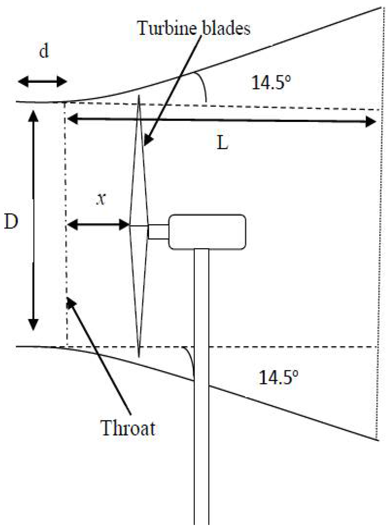
It is indisputable that a flanged diffuser augments the power output of a BWT. However, the addition of the flange to the diffuser is accompanied by the addition of the production cost and the weight of the diffuser augmented wind turbine (DAWT), which in the end increase the cost of energy. A plain conical diffuser can produce comparable power output when optimally designed. Unlike in the BWT technology where the rotor cross-sectional area and the wind speed are the main parameters in wind energy extraction, in ducted wind turbines, geometrical parameters of the duct such as the duct expansion angle and the non-dimensional length
also come into play. L is the length of the diffuser while D is the throat diameter (the narrowest part of the duct) of the duct. The performance of diffusers, among other factors depend mainly on geometrical shape parameters [
8].
The impact of geometrical parameters on the performance of ducted wind turbines has led several researchers to investigate optimum operating values of these parameters. Gibson [
9], in his work, “On the flow of water through pipes and passages having converging or diverging boundaries”, is probably one of the first to investigate optimum expansion angles for conical and rectangular diffusers. For conical diffusers he found the optimum expansion angle to be 6°, and 11° for rectangular diffusers. Over the years, several other researchers worked on these geometrical parameters and came out with various conclusions [
10,
11,
12,
13].
Wind power is proportional to the cube of the wind speed. In ducted wind turbines, the ducts should be designed to produce the highest possible wind speed augmentation at the throat of the duct. This can only be achieved by determining optimum geometrical parameters of the desired duct. In this work, optimum geometrical parameters for a plain conical diffuser were experimentally determined. An optimized plain conical DAWT was designed, constructed, and field tested.
2. Materials and Methods
There were two main tasks which were carried out in the execution of this project. The first task had to do with the determination of the optimum geometrical shape parameters for conical diffusers, and the second was the design, construction, and field testing of the optimized plain conical DAWT.
2.1. Determination of Optimum Geometrical Shape Parameters for Conical Diffusers
In reference [
13], we presented experimental work with empty conical diffusers. The thrust of the experiments was to determine the relationship between the wind speed augmentation
and the geometrical shape parameters of the diffusers. The geometrical parameters under study were the diffuser expansion angle
and the non-dimensional length
. From these experiments optimum geometrical parameters which give maximum wind speed augmentation
at the throat of the diffuser were determined.
Table 1 summarizes the obtained results from these experiments.
With reference to
Table 1, from
to
,
increased from 1.48 to 1.55. An increment of 4.7% was achieved in this regard. This means that larger diffusers have greater wind speed augmentation. It is also observed that each
ratio has its own optimum diffuser expansion angle and these expansion angles decrease with increase in
.
2.2. Design, Construction, and Field Testing of the Optimized Plain Conical DAWT
Table 1 shows optimum geometrical parameters for conical diffusers to achieve maximum wind speed augmentation at the throat of the diffuser. Any
ratio given in
Table 1 can be used in the design and construction of a plain conical DAWT system to optimize the power output of a BWT. However, while large diffusers produce a higher
, the following aspects must also be considered in selecting the design
:
- (a)
Cost: large ratios calls for large structures which need more materials which result in high cost. This increase in cost renders the technology expensive as it will affect the cost of energy.
- (b)
Bulkiness: large structures are more inert, as a result they cannot respond quickly to wind direction changes especially when the wind direction changes quickly in a very short space of time. There is some time lag between the wind direction change and the response of the system. In that regard the system cannot fully utilize the potential of the prevailing wind and that renders the whole system ineffective [
14].
- (c)
Aesthetics: while the system is designed to meet human energy needs, it must at the same time be environmentally aesthetic. That is, without philosophizing this aspect, its visual impact should be beautiful.
Taking into account the above factors, a non-dimensional length of
and optimum diffuser expansion angle
was used in the design of the plain conical DAWT system.
Table 2 shows the design parameters of the plain conical DAWT.
The diffuser was designed with an inlet shroud to funnel the wind into the diffuser. A Dolphin Z 300-WB wind turbine with a rotor diameter of 1190 mm was used in this experiment. A blade clearance of 3 mm was adopted.
Figure 1 shows a schematic diagram of the designed optimized plain conical DAWT system.
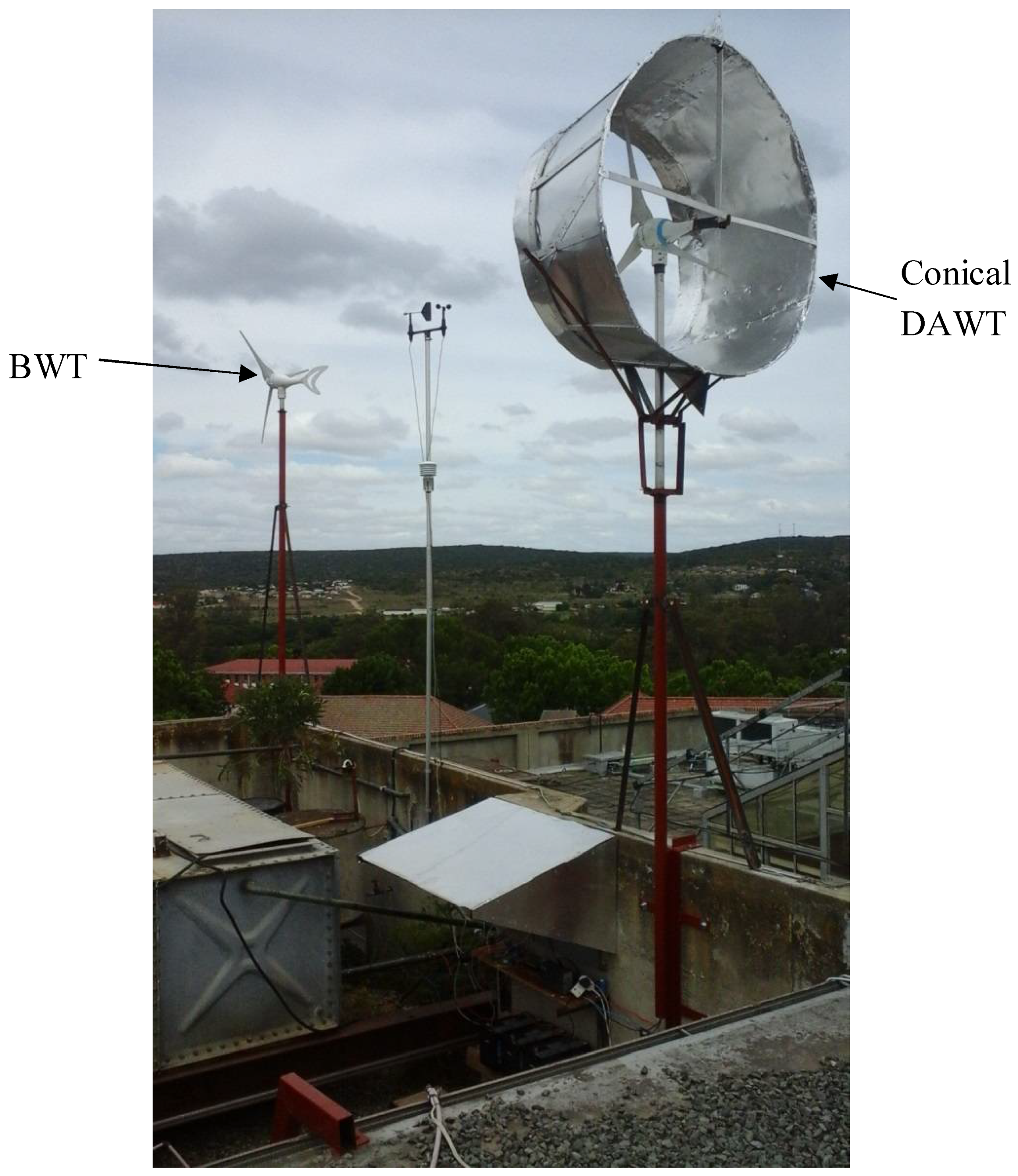
The diffuser was constructed using a 0.5 mm thick aluminium metal sheet. The constructed conical DAWT is shown in the experimental set-up of
Figure 2. The performance of the conical DAWT was field tested by comparing its power out with that of a BWT. A twin decentralized wind energy system which comprised the optimized plain conical DAWT system and a BWT was erected (
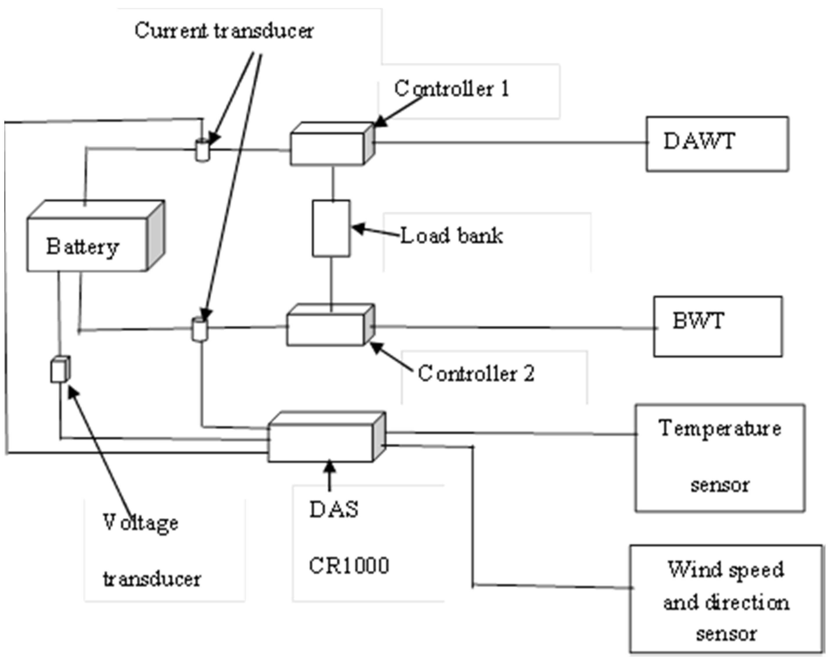
Figure 2). The aim was to measure and compare the power output of both systems. A Dolphin Z 300-WB wind turbine rotor was used in both cases. Both systems were connected to the same battery bank and load bank. Each system had its own charge controller. The data acquisition system (DAS) had a CR 1000 data logger for the storage of the experimental data.
Figure 3 shows the diagram of the experimental set-up used.
The experiment was done over three months, October to December 2015. The power output was calculated as the product of the measured output voltage and the corresponding current from each system. The voltage was measured by a CE-VZ02-32MS1-0.5/0-20V voltage transducer and the output current was measured by CE-IZ04-32A2-1.0/30 current transducer. These sensors were connected to a CR 1000 data logger.
Figure 3 shows the experimental set-up of the experiment.
3. Results and Discussion
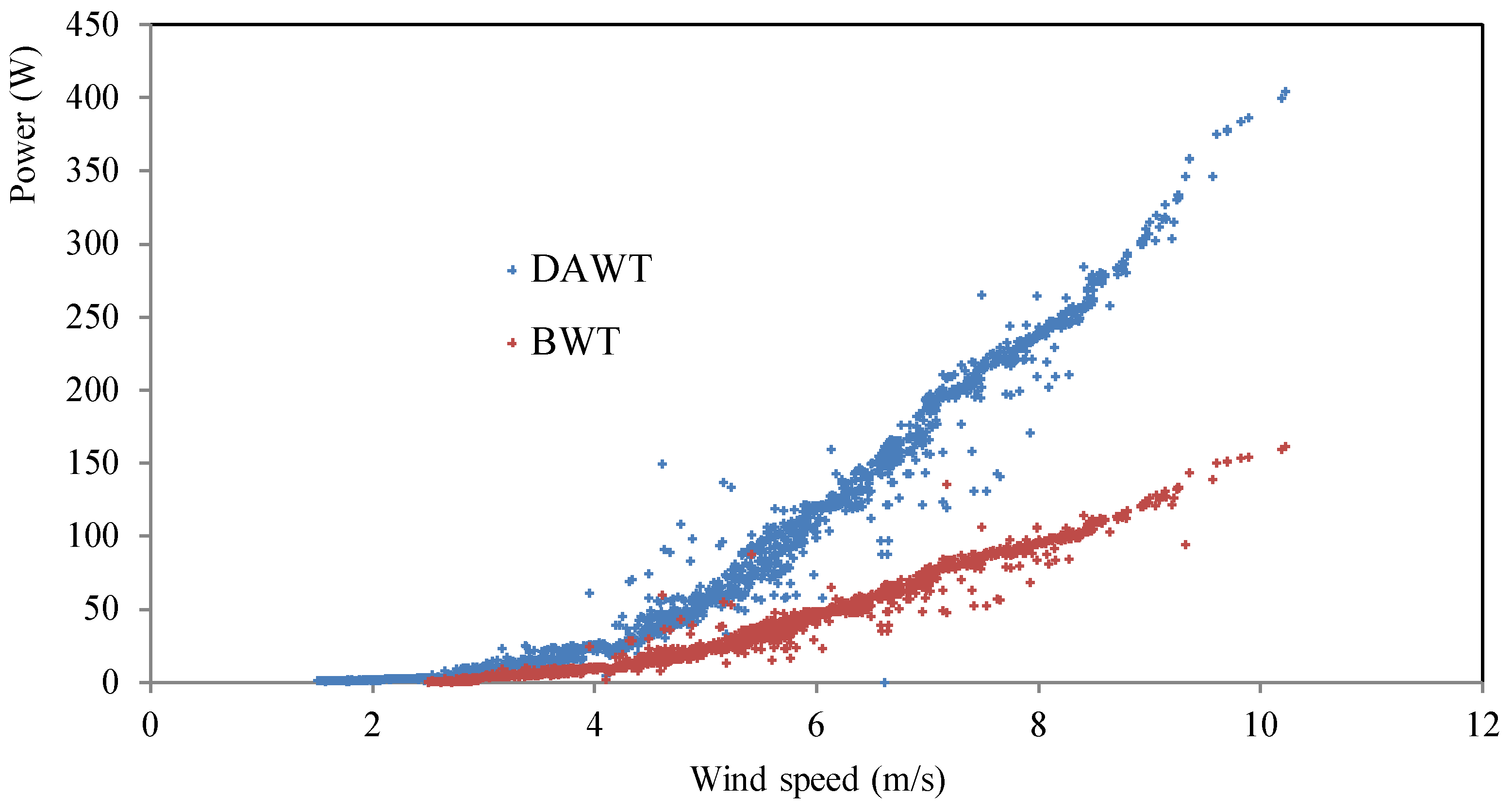
Figure 4 shows scatter graphs for wind speed against power output for both the BWT and the optimized plain conical DAWT. A maximum wind speed of 10.5 m/s was experienced during the experimental period. It can be observed in
Figure 4 that the two wind energy systems did not have the same cut-in wind speed. The plain conical DAWT had a cut-in wind speed of approximately 1.6 m/s, while that of the BWT was 2.5 m/s.
The introduction of the optimized plain conical diffuser in the DAWT reduced the cut-in wind speed of the rotor from 2.5 m/s to 1.6 m/s and increased the power output of the wind turbine encased in the diffuser. It was observed that the power output of the optimized conical DAWT was 2.5 times that of the BWT. Therefore, the use of an optimized plain conical DAWT enables wind energy extraction in those areas which are deemed low speed areas. This is due to the wind speed augmentation by the optimized plain conical diffuser.
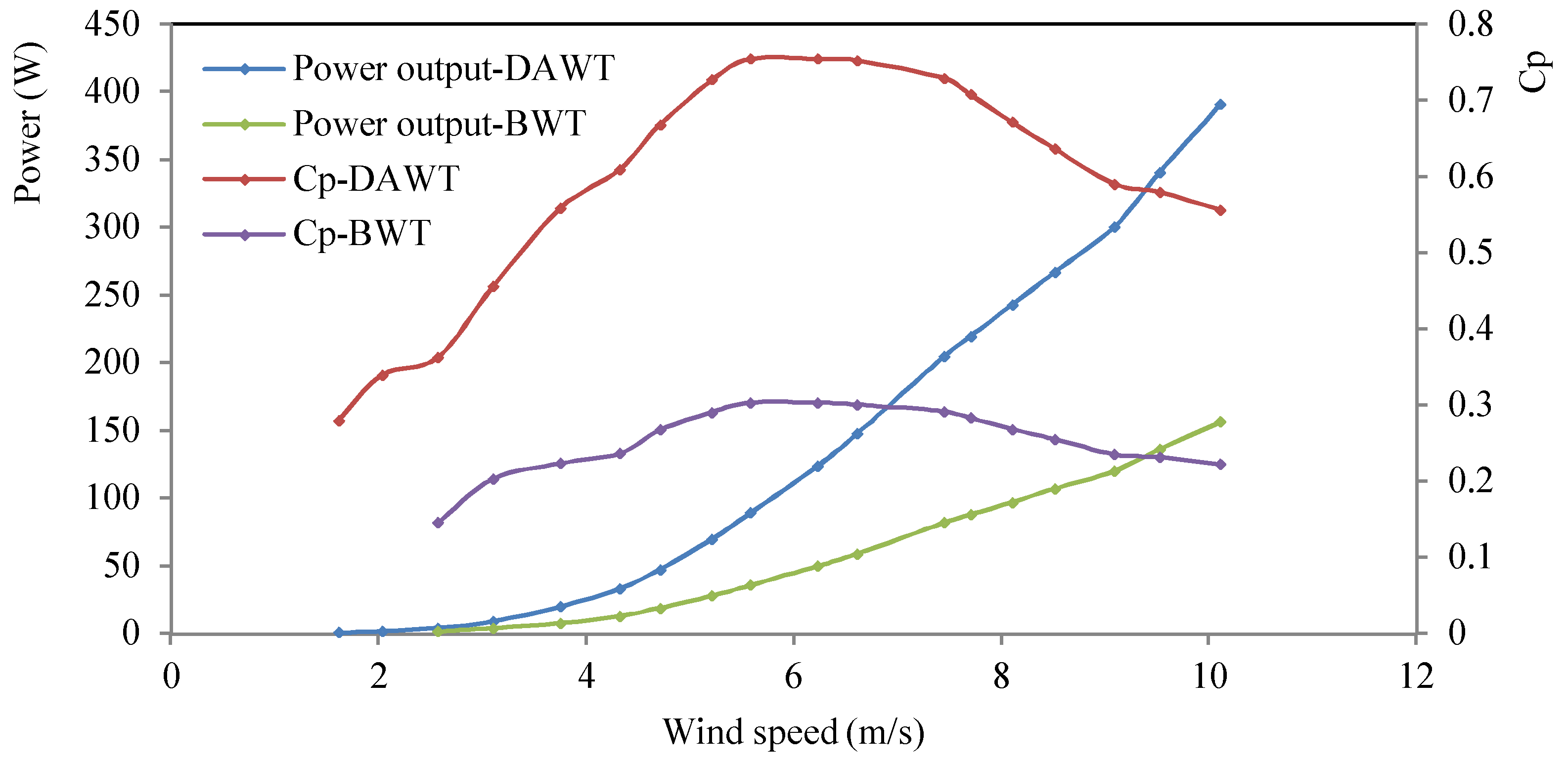
Figure 5 shows graphs of the coefficient of performance (
) and power output for the BWT and the optimized plain conical DAWT.
is the ratio of the wind power obtained by the wind turbine rotor to the wind power available in the wind. With reference to
Figure 5, it can be observed that the
of a wind turbine increased with wind speed up to its maximum value and then decreased. The maximum
for the BWT was found to be 0.3 and that of the conical DAWT was 0.75. The maximum
occurred at a wind speed range of 5.6 m/s to 6.6 m/s for both systems. The performance of the optimized plain conical DAWT was 2.5 times that of the BWT. The same result was also found by [
15,
16] for a flanged-diffuser. This finding clearly shows that an optimized plain conical DAWT can produce the power output comparable to that of a flanged-DAWT.
An optimized plain conical DAWT and a flanged-DAWT produce comparable power outputs but the optimized plain conical DAWT has two advantages over its counterpart. It is less inert as compared to the flanged-DAWT. The addition of the flange adds the inertia of the flanged-DAWT system, thus it cannot respond to wind speed and direction changes quickly. Therefore, it cannot utilize the full potential of the wind. It is important however to highlight that both the optimized plain conical DAWT and the flanged-DAWT have slow response to wind speed and direction changes as compared to the BWT but the flanged-DAWT is worse. The addition of the flange also increases the material used and thus comes with cost. This results in the increase of the cost of energy.
In general, these low speed wind turbines are used as decentralized systems in rural areas. The addition of the flange need some expertise which most rural people do not have. They have to hire qualified personnel to do the construction for them and this adds on the cost of energy. Given the optimum geometrical values of the plain conical diffuser, they can do the construction of the optimized plain conical DAWT in their backyard.
4. Conclusions
An optimized plain conical DAWT augments the power output of a BWT. For the power output was increased by a factor of 2.5. Besides the increased airflow rate characteristic of diffusers past the rotor, the optimized plain conical DAWT also reduces the cut-in wind speed of the rotor. This characteristic enables the optimized plain conical DAWT to be used for wind energy extraction in those areas deemed low wind speed areas where a BWT cannot operate.
The power output of an optimized plain conical DAWT is comparable to that of a flanged-DAWT. Optimized plain conical DAWTs are a better technology because they are less inert and their production cost is also less. Their construction does not require expertise such that even rural people can construct them in their back yard. This is not possible with the flanged-DAWT because it requires some expertise to handle the flange. Therefore, optimized plain conical DAWTs can replace flanged-DAWTs.
Author Contributions
P.-M.M. conceived the idea of Optimization of the power output of a BWT by a plain conical DAWT, conducted all experiments with P.M., and authored the paper. G.M. analyzed the data.
Funding
This research received no external funding.
Acknowledgments
The authors of this paper would like to express their sincere gratitude to the Goven Mbeki Research and Development Centre for their financial support.
Conflicts of Interest
The authors declare no conflict of interest.
References
- Roeth, J. Wind Resource Assessment Handbook; Energy Research and Development Authority (NYSERDA): New York, NY, USA, 2010; pp. 1–10. [Google Scholar]
- Watson, S.J.; Infield, D.G.; Barton, J.P.; Wylie, S.J. Modelling of the performance of a building-mounted ducted wind turbine. J. Phys. Conf. Ser. 2007, 75, 012001. [Google Scholar] [CrossRef]
- Abea, K.; Nishidab, M.; Sakuraia, A.; Ohyac, Y.; Kiharaa, H.; Wadad, E.; Satod, K. Experimental and numerical investigations of flow fields behind a small wind turbine with a flanged diffuser. J. Wind Eng. Ind. Aerodyn. 2005, 93, 951–970. [Google Scholar] [CrossRef]
- Toshimitsu, K.; Nishikawa, K.; Haruki, W.; Oono, S.; Takao, M.; Ohya, Y. PIV measurements of flows around the wind turbines with a flanged-diffuser shroud. J. Therm. Sci. 2008, 17, 375–380. [Google Scholar] [CrossRef]
- Toshimitsu, K.; Kikugawa, H.; Sato, K.; Sato, T. Experimental investigation of performance of the wind turbine with the flanged-diffuser shroud in sinusoidally oscillating and fluctuating velocity flows. Open J. Fluid Dyn. 2012, 2, 215–221. [Google Scholar] [CrossRef]
- Ohya, Y.; Uchida, T.; Karasudani, T.; Hasegawa, M.; Kume, H. Numerical Studies of Flow around a wind turbine equipped with a flanged-diffuser shroud using an Actuator-disk model. Wind Eng. 2012, 36, 455–472. [Google Scholar] [CrossRef]
- Ohya, Y.; Karasudania, T.; Sakurai, A.; Abe, K.; Inoue, M. Development of a shrouded wind turbine with a flanged diffuser. J. Wind Eng. Ind. Aerodyn. 2008, 96, 524–539. [Google Scholar] [CrossRef]
- White, F.M. Fluid Dynamics, 7th ed.; MacGraw-Hill: New York, NY, USA, 2009; pp. 404–408. ISBN 978-0-07-352934-9. [Google Scholar]
- Gibson, A.H. On the Flow of Water Through the pipes and passages having Converging and Diverging Boundaries. Proc. R. Soc. Lond. A 1910, 83, 366–378. [Google Scholar] [CrossRef]
- Salim, B. Effect of geometrical parameters on the performance of wide angle diffusers. Int. J. Innov. Res. Sci. Eng. Technol. 2013, 2, 4178–4191. [Google Scholar]
- Djebedjian, B. Diffuser optimization using computational fluid dynamics and Micro-genetic algorithms. Mansoura Eng. J. 2003, 28, 15–34. [Google Scholar]
- Chaker, R.; Kardous, M.; Alou, F.; Nasrallah, S.B. Relationship between open angle and aerodynamic performances of a DAWT. In Proceedings of the Fourth International Renewable Energy Congress, Sousse, Tunisia, 20–22 December 2012. [Google Scholar]
- Masukume, P.M.; Makaka, G.; Tinarwo, D. Optimum geometrical shape parameters for conical diffusers in ducted wind turbines. Int. J. Energy Power Eng. 2016, 5, 177–181. [Google Scholar]
- Masukume, P.M.; Makaka, G.; Tinarwo, D. Technoeconomic analysis of ducted wind turbines and their slow acceptance on the market. J. Renew. Energy 2014. [Google Scholar] [CrossRef]
- Sarwar, M.M.; Nawshin, N.; Imam, M.A.; Mashud, M. A new approach to improve the performance of an existing small wind turbine by using a diffuser. Int. J. Eng. Appl. Sci. 2012, 4, 31–42. [Google Scholar]
- Ohya, Y.; Karasudani, T. A shrouded wind turbine generating high output power with Wind-lens technology. Energies 2010, 3, 634–649. [Google Scholar] [CrossRef]
© 2018 by the authors. Licensee MDPI, Basel, Switzerland. This article is an open access article distributed under the terms and conditions of the Creative Commons Attribution (CC BY) license (http://creativecommons.org/licenses/by/4.0/).


