Abstract
Cooperative communication (CC) is one of the best solutions to overcome channel fading and to improve channel capacity. However, most of the researchers evaluate its performance based on mathematical modeling or by simulations. These approaches are often unable to successfully capture many real-world radio signal propagation problems. Hardware based wireless communication test-bed provides reliable and accurate measurements, which are not attainable through other means. This research work investigates experimental performance analysis of CC over direct communication (DC) in the lab environment. The experimental setup is built using Universal Software Radio Peripheral (USRP) and Laboratory Virtual Instrument Engineering Workbench (LabVIEW). A text message is transmitted by using Phase Shift Keying (PSK) modulation schemes. The setup uses amplify and forward (AF) relaying mode and two time slot transmission protocols. The maximum ratio combining (MRC) technique is used for combining SNR at the receiver. Channel capacity analysis is performed in order to evaluate the performance of CC over DC with and without obstacle. Moreover, optimal position of the relay is also analyzed by varying the position of the relay. Extensive experiments are carried out in the lab environment to evaluate the performance of the system for different hardware setups. The results reveal that cooperative communication attains significant improvement in terms of channel capacity of the system.
1. Introduction
The 5G wireless communication services on one hand are aimed for providing basic conventional telecommunication services, such as speech, web browsing, video download and upload, social networking, etc. On the other hand, they are supposed to provide wide range of services by linking a range of devices and sensors in the internet of things, for example, the smart city applications. The networks providing such services consist of large number of devices that are low cost and consume low energy. These devices cooperate to communicate the data to the desired place. Cooperative communication (CC) is commonly preferred due to high/rapid exchange rate, range, and reliability. Furthermore, it has the tendency to overcome multi-path fading and provide diversity gain. The other features deal with spatial and user diversity by combining various signals that are received through different routes from multiple users at receiver node. The CC can significantly enhance the system performance in terms of reliability and channel capacity. The cooperative communication system consists of a virtual multiple input multiple output (VMIMO), where single-antenna cooperate with other antennas thus forming a multiple antenna system. During cooperation, the cooperative diversity gain of MIMO systems can be achieved by reducing the cost of physical antenna array at each node. Due to the high data rates and cost effective solutions, cooperative communication is considered to be one of the most efficient technique, and it can be exploited for the 5G wireless networks as well.
Cover and Gamal [1] introduced the concept of relay in communication system and it acts as a door opening work in this direction. Later on, a lot of research work was carried using different relaying schemes and protocols. In [2,3], evaluated system performance using bit error rate (BER) analysis [4,5,6]. Similarly, General performance analysis bounds were also found for various CC scenarios [7]. However, majority of the research work evaluated the CC network performance either mathematically or by simulation. Theoretical or mathematically modeling investigation provides guidance for real time system implementation, with many real time factors with assumptions and limitations [8]. Regarding simulation, it has been generally acknowledged that results that are produced through such process often failed to provide the actual hurdle that is faced in real world radio signals. By considering all of the factors involved in radio wireless communication system, there is still a challenge how much performance improvement by cooperative communication can bring in real wireless environment [9]. To analyze real world radio communication factors, a real time testbed should be introduced to analyze the overall CC network performance. It should provide a realistic approach to evaluate the wireless system.
Many researchers are working on different existing platforms to evaluate the CC networks. The commodity wireless card (e.g., 802.11 NIC) is one of the examples of these platforms [10]. However, the hardware of cooperative communication has extra requirements to implement physical layer functions, which cannot be resolved by these commodity wireless cards. Aside from these wireless cards, various testbeds are introduced using digital signal processor (DSP) kits or field programmable gate array (FPGA) boards [11]. While using these platforms, real time implementation and hardware issues can be resolved. The cost of implementation and hardware programming sets new era in research communities. But still, the above mentioned testbed is less efficient to solve the basic functions to implement various MAC layer protocols.
The best solution against these problems is software defined radio (SDR) that is based on general purpose processor. They are more suitable for implementation of signal processing and MAC layer functions. They provide more efficient hardware programming environment. Universal Software Radio Peripheral (USRP) and GNU Radio, used as hardware and software platform [12,13] are most popularly used SDR platforms in these days. However, these platforms are not widely used for cooperative communication testbed. So, this is one of the reasons that existing one can perform very limited number of radio functions [14]. They are only used for selective cooperative communications. In [15], an experimental testbed was established by using Ettus Research USRPs N210 with SBX daughterboard, VERT2450 antennas, and GNU Radio. The obtained results concluded that the strength of the signal at the receiver is significantly improved by employing the relay in the wireless network. In all of the previous research work, performance metrics of experimental analysis is based on BER, signal strength, and transmit power.
In this paper, USRP and LabVIEW are used to implement the cooperative network testbed. LabVIEW software and NI USRP hardware provides affordability, functionality, and flexibility to deliver an ideal software-defined radio prototyping platform. In this experimental hardware, setup is interfaced with LabVIEW by Gigabit Ethernet port. It offers the signal processing capabilities for the modulation and demodulation of signals streaming to and from NI USRP hardware. Toolkits from LabVIEW software offer functional blocks for numerous analog and digital modulation methods and signal processing algorithms for real-world radio signals.
The methodology that is used for implementation provides a platform for the evaluation of cooperative network performance on USRP and LabVIEW based testbed. This research paper provides the following contributions:
- Design and implementation of a complete-functional testbed framework based on USRP and LabVIEW to support the cooperative communication, which includes a signal processing for the physical layer implementation of cooperative communication.
- Different modulation schemes are used to verify the performance of the system.
- Capacity analysis of cooperative network using LabVIEW and NI-USRP based test-bed.
- Extensive experiments are performed with and without obstacles in the lab environment.
- Determine the optimal position of the relay placement in the cooperative system.
The result shows the significant capacity gain of CC over DC. The response of the system is very similar to the theoretical and simulation analysis. This paper is organized in the following sequence: in Section 2, related research works are reviewed. In Section 3, system model of the cooperative network using USRP is introduced. In Section 4, the experimental setup is discussed. In Section 5, the methodology used in the research work is explained. Section 6 provides the experimental results and discussions. In the last, Section 7, the conclusion and future work directions are presented.
2. Related Work
Previous research indicates that the performance of CC networks in real time wireless systems has been analyzed and evaluated on the basis of various testbeds. The testbed comprised of various kind of hardware design and functionalities. Regarding the performance of testbed, the BER approach was commonly adopted. For example, author et al. [8] exploited CoopMAC protocol on 802.11 standard devices in connection with open source platform. They performed a number of experiments on relays ranging from 3 to 10 in a single testbed. Similarly, in [12], commodity hardware multiple relays were utilized for implementing testbed, where the selection of strong signal was either from sender or relay without taking into account the signal combining technique. However, the drawback of this approach is that the actual cooperative diversity gain cannot be achieved at the destination. Furthermore, this hardware is not easy to modify at MAC layer and almost impossible to alter at physical layer, where actually CC technology is applied.
To overcome the limitations of commodity hardware, later on, fast processors and boards like DSP and FPGA based testbeds were used to analyze CC system. For example, Zetterberg et al. [11] developed a testbed using a DSP kit with laptop or PC, and commonly used relaying schemes, such as amplify and forward (AF), Decode and forward (DF) and Compress and forward (CF). Furthermore, at the destination for getting the actual diversity gain of CC network, MRC technique was applied. The benefit of these testbeds, on the one hand, is that they provide hardware and software flexibility, and on the other hand they are cost effective. Similarly [16,17] developed a Wireless Open Access Research Platform (WARP) that uses amplify and forward relaying scheme and is based on the orthogonal frequency division multiplexing (OFDM) technique and distributed Alamouti transmit diversity scheme. However, the drawback of this approach on the one hand is that due the absence of external clock interface in hardware platform, the multi-relay synchronization becomes difficult. On the other hand, it is very expensive.
The platform of USRP and GNU Radio is becoming very popular because of the implementation of all signals processing in CC testbed on it. The open source availability of GNU radio software made it possible to add new functionality and modifications. Due to its flexibility and popularity, a lot of novel ideas have been proposed and implemented on GNU Radio based testbed, including efficient analog network coding [18,19,20].
Distributed asynchronous cooperation (DAC) is introduced in [21], and the tradeoff between the diversity gain and the reduction in multiplexing opportunities is analyzed. Novel cross layer techniques are also proposed to verify the real time environment effect. To analyze the performance of multi-antenna system GNU radio based testbed is also used. In [22], GNU Radio based testbed to build hydra prototype and analyze the performance of MIMO system, and on basis of the experimental results, rate adaptation protocol is proposed. In [23], range extension is observed by comparing multiple relay network with single relay network. While [24] analyzed the performance of DF and selective DF without signal combining technique with GNU Radio based testbed. In [25], signal combining of CC was evaluated but optimal position of the relay and channel capacity have not been evaluated on this platform. These are most important facts to evaluate the performance of the system. In this research channel capacity analysis is evaluated for the cooperative network using USRP and LabVIEW.
3. System Model
The system model consists of three main modules; i.e., source (S), relay (R), and destination (D), as shown in the Figure 1. Each module is equipped with single antenna.
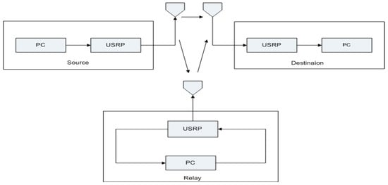
Figure 1.
System model.
3.1. Source Operation
A text message is generated in PC in LabVIEW environment. Software defined BPSK, 4PSK, and 8PSK digital modulation schemes are used to transmit data over the wireless channel by using USRP kit.
3.2. Relay Operation
Relay receives text message from source using USRP kit. The received signal is amplified in PC using LabVIEW. Amplified signal is again forwarded to USRP kit and then retransmitted towards the destination.
3.3. Optimal Position of the Relay
To determine the optimal position of the relay, following three positions of the relay are analyzed.
At position ‘A’ relay is placed near to the source and away from the destination, as shown in Figure 2. The distances from source to destination, source to relay, and relay to destination are 12 m, 4.2 m, and 8.1 m, respectively.
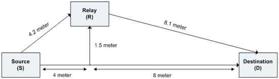
Figure 2.
Position A: Relay is near to source.
At position ‘B’, relay is placed at equally distance from source and destination, as shown in Figure 3. The distances from source to the destination, source to relay and relay to destination are 12 m, 6.2 m, and 6.2 m, respectively.
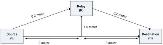
Figure 3.
Position B: Relay is center.
At position ‘C’, relay is placed away from source and near to destination, as shown in Figure 4. The distances from source to destination, source to relay and relay to destination are 12 m, 8.1 m, and 4.2 m, respectively.
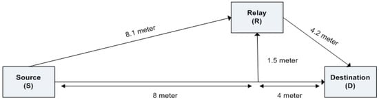
Figure 4.
Position C: Relay near to destination.
3.4. Transmission Protocols
The Naber’s two time slot transmission protocol is applied for the direct path and cooperative path [24]. This protocol is used because the source is kept silent in the second time slot, and hence less transmit power is consumed by the system. The signal moves from source to destination and relay path in two time slots. In Table 1, two time slot transmission protocol is given. In time slot 1, the node S transmits the signal to node D and node R. In the time slot 2, only the node R transmits signal to node D. The relay is using AF scheme.

Table 1.
Transmission Protocol [26].
3.5. Input-Output Equations
The data from node S is transmitted via direct and a relay path.
Time Slot 1:
The received data equation at node D for time slot 1 is shown as in Equation (1) [8].
where is the channel response between is source and destination, is the transmit signal power from source to destination, x is the signal transmitted, and is the channel noise between S node to D node. The signal that is received at the node R in first time slot is shown by:
where is channel response between source and relay are, is the transmit signal power from source to relay, x is the transmitted signal, and is the channel noise between S node to R node.
Time Slot 2:
In second time slot, the relay receives the signal from S node, amplifies it, and retransmits it to the D node. The received signal through the R node in time slot 2 is given as:
where channel response between relay and destination is , is the signal power, is the transmitted signal, and is the channel noise between the S node to R node. Signal from the S and R node is combined using MRC at D node. The MRC at the D node is given as:
3.6. Receiver
In the receiver operation SNR received from the transmitter and relay are measured and combined at receiver. Performance of the system is measure by using Shannon capacity theorem that is given in Equation (5).
In Equation (5), C is the channel capacity, B is the bandwidth, and SNR is the signal to noise ratio.
4. Experimental Setup
Following experimental testbed is set in the lab environment for capacity analysis of cooperative network using USRP kits.
In setup 1, as shown in Figure 5, three USRPs and PCs are used for the source destination and relay in the lab environment without any obstacle. USRPs moves to the maximum distance in the lab and relay USRP is placed at three different positions.
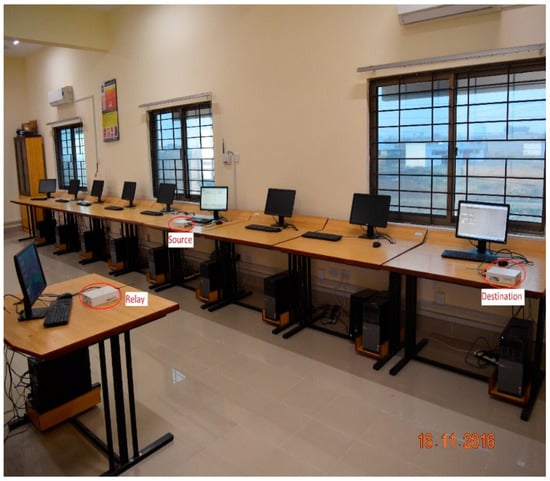
Figure 5.
Experimental Setup of cooperative communication (CC) without obstacle.
In setup 2, as shown in Figure 6, a wooden obstacle of 60 × 45 × 1.5 cm dimension is placed between the source and the destination. No obstacle is placed in the relay destination path.
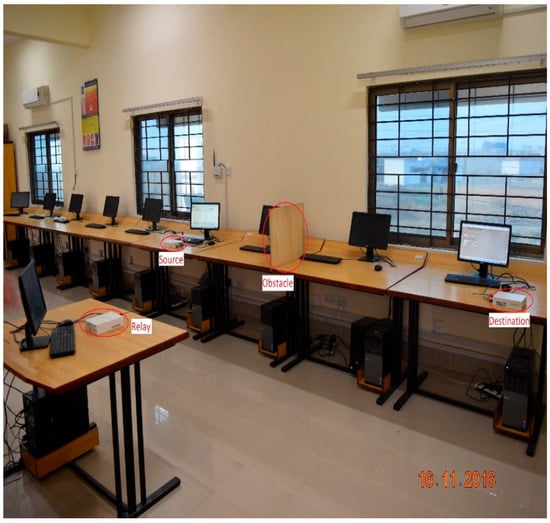
Figure 6.
Experimental Setup of CC with obstacle.
5. Methodology
The methodology that is used in this research is as follows. A text message is transmitted over the direct path and relay path by using different digital M-PSK modulation schemes. The performance is analyzed by varying the transmit antenna gain and the received SNR is measured at the destination. The capacity of channel is measured by using Shannon capacity theorem. In CC, the AF relaying mode is used with amplifying gain of 10 dB. Two time slot transmission protocols are used. In first time slot, text message is transmitted to relay and destination for 50 s. In the second time slot after 20 s delay, relay again retransmits text to the receiver for 50 s. The receive SNR form direct path and relay path is combined at the receiver using the MRC technique. At first capacity analysis for experimental, setup 1 is performed and then the same analysis is performed for setup 2. Optimal position of the relay is analyzed by varying the position of the relay. First relay is placed near the source then at center, and finally near the destination. Extensive experiments are performed within the lab environment. The following setup and system parameters are analyzed for the performance investigation of the system shown in Table 2.
Table 2.
System parameters.
6. Results and Discussion
Based upon the system model and experimental setups, the capacity analysis is performed for several M-PSK modulation schemes, as discussed below.
6.1. Experimental Analysis of CC over DC Without Obstacle
The following experimental analysis is based on the performance evaluation of DC with CC. In this setup, no obstacle is placed in either direct or relay path.
Figure 7 shows the experimental results of DC and CC without any obstacle. The performance of CC dominates the DC. From Table 3, the average channel capacity gain of CC over DC is 14.44% for BPSK, 14.59% for QPSK, and 14.75% for 8PSK, respectively.
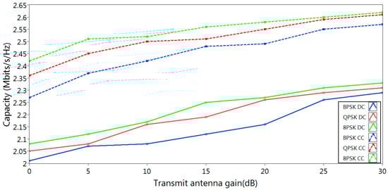
Figure 7.
Performance analysis of CC over direct communication (DC) without obstacle.
Table 3.
Performance comparison of DC with CC without any obstacle.
6.2. Experimental Analysis of CC over DC with Obstacle
The following experimental analysis is based on the performance evaluation of DC with CC. A wooden obstacle is placed in the direct path to analyze the performance of the system.
Figure 8 shows the experimental results of DC and CC with obstacle. Here, significant performance improvement is obtained for CC as compared to DC. From Table 4, it can be seen that average channel capacity gain of CC over DC is 15.97% for BPSK, 16.12% for QPSK, and 17.01% for 8PSK respectively.
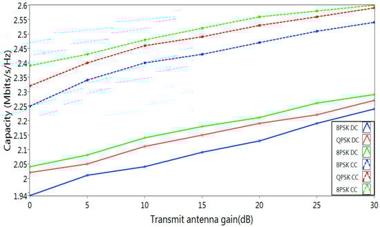
Figure 8.
Performance analysis of CC over DC with obstacle.
Table 4.
Performance comparison of DC with CC with obstacle.
6.3. Optimal Position of the Relay without and with Obstacle
Capacity analysis is performed for three different positions of relay for evaluating the optimal position. The capacity gain is achieved for the optimal position by using the following cases:
- Case 1: Capacity gain of Position A over B
- Case 2: Capacity gain of Position A over C
- Case 3: Capacity gain of Position B over C
In this setup, no obstacle is placed in between the source and the destination and relay path. The performance is analyzed by varying the position of the relay at position A, B, and C. Capacity gain is compared among all the three position of the relay.
Figure 9 shows the results of evaluation for the optimal position of the relay without obstacle. The relay position B performance is better than Position A and Position C. While the relay position A performance is better than C.
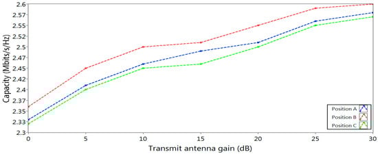
Figure 9.
Optimal position without obstacle.
From Table 5, the average capacity gain of relay position B over A and C are 1.35% and 1.90%, respectively. On the other hand average capacity gain of relay position at A is 0.54% over C. The resulted analysis shows that optimal position of the relay is at point B. This means if relay is placed equally distance from the source and destination it provides more capacity gain.
Table 5.
Optimal position of the relay without obstacle.
In this setup, when the obstacle is introduced between source and destination, performance is analyzed for all three position A, B, and C. Capacity gain is calculated for all the above three cases. In Figure 10 shows the results of evaluation for the optimal position of the relay with obstacle. The relay position at B performance is better than A and C. While the relay position at A performance is better than C. From Table 6, the average capacity gain of relay position at B is 1.22% and 1.70% over A and C. On the other hand, the average capacity gain of relay position at A is 0.47% over B position.
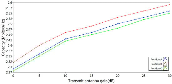
Figure 10.
Optimal position with obstacle.
Table 6.
Optimal position of the relay with obstacle.
7. Conclusions
Cooperative communication is one of the best solutions to overcome the multipath fading and provides diversity gain. In this research work, an experimental testbed comprised of USRP and LabVIEW is used to build a cooperative network SDR platform. Extensive experiments are carried out for capacity gain of CC over DC in lab environment. Experimental performance analysis shows that CC significantly improves the performance of the system than DC. Experimental analysis shows an increase in the transmit antenna gain results in improving the SNR at receiver. High SNR provides more channel capacity by using higher order PSK modulation. The performance of CC significantly increases the system reliability and the channel capacity of the system with and without obstacle environment. It is also analyzed that channel capacity increases by placing the relay at center between source and destination.
8. Future Recommendations
As a future extension to this work, a cooperative communication platform can be implemented with advance channel coding techniques and multiple relays. Automatic detection of digital modulation can be applied. This system can be made spectral efficient system by using orthogonal frequency division multiple accesses. On this testbed, decode and forward relaying mode can be possible by decoding the text message at the relay, which will be similar to receiver operation at the cost of system complexity. The other combining schemes can be implemented at the receiver like selection combining, equal gain combiner, etc. Currently, this work is implemented in lab environment but it can be extended to outdoor environments. This research can be further extended to future 5G networks like Internet of thing, vehicle to vehicle communication, machine to machine communication, and fully functional software defined radios.
Author Contributions
S.A.K.T., M.R., M.B.K., I.J., F.N. are the principle investigator and contributed in the designing and establishment of experimental tested, configuring of NI-USRP with LabVIEW, LabVIEW Programing Including generation of text message, designing virtual instruments for transmitter, receiver and relay, real time measurements and analysis of the results respectively; F.A.K. contributed in analysis and presentation of the results, drafting and proof reading; S.A.S., X.Y. are the international research collaborators contributed in simulations, mathematical modeling and funding this research; A.A.N. is also research collaborator helped in drafting author reply, comparative analysis, proof reading and rephrasing.
Conflicts of Interest
The authors declare no conflict of interest.
References
- Cover, T.; Gamal, A.E. Capacity theorems for the relay channel. IEEE Trans. Inf. Theory 1979, 25, 572–584. [Google Scholar] [CrossRef]
- Bletsas, A.; Khisti, A.; Reed, D.P.; Lippman, A. A simple cooperative diversity method based on network path selection. IEEE J. Sel. Areas Commun. 2006, 24, 659–672. [Google Scholar] [CrossRef]
- Laneman, J.N.; Wornell, G.W.; Tse, D.N. An efficient protocol for realizing cooperative diversity in wireless networks. In Proceedings of the 2001 IEEE International Symposium on Information Theory, Washington, DC, USA, 29 June 2001; p. 294. [Google Scholar]
- Hunter, T.E.; Sanayei, S.; Nosratinia, A. Outage analysis of coded cooperation. IEEE Trans. Inf. Theory 2006, 52, 375–391. [Google Scholar] [CrossRef]
- Kramer, G.; Gastpar, M.; Gupta, P. Cooperative strategies and capacity theorems for relay networks. IEEE Trans. Inf. Theory 2005, 51, 3037–3063. [Google Scholar] [CrossRef]
- Laneman, J.N.; Tse, D.N.; Wornell, G.W. Cooperative diversity in wireless net-works: Efficient protocols and outage behavior. IEEE Trans. Inf. Theory 2004, 50, 3062–3080. [Google Scholar] [CrossRef]
- Host-Madsen, A. Capacity bounds for cooperative diversity. IEEE Trans. Inf. Theory 2006, 52, 1522–1544. [Google Scholar] [CrossRef]
- Khan, I.; Rajatheva, N.; Tanoli, S.; Jan, S. Performance analysis of cooperative network over nakagami and rician fading channels. Int. J. Commun. Syst. 2014, 27, 2703–2722. [Google Scholar] [CrossRef]
- Kumar, N.; Bhatia, V. Outage probability and average channel capacity of amplify-and-forward in conventional cooperative communication networks over rayleigh fading channels. Wirel. Pers. Commun. 2016, 88, 943–951. [Google Scholar] [CrossRef]
- Korakis, T.; Tao, Z.; Makda, S.; Gitelman, B.; Panwar, S. To Serve is to Receive Implications of Cooperation in a Real Environment; Proceedings of the Networking: Atlanta, GA, USA, 2007. [Google Scholar]
- Zetterberg, P.; Mavrokefalidis, C.; Lalos, A.S.; Matigakis, E. Experimental investigation of cooperative schemes on a real-time dsp-based testbed. EURASIP J. Wirel. Commun. Netw. 2009, 1, 368752. [Google Scholar] [CrossRef]
- Gnu Radio. Available online: http://www.gnu.org/software/gnuradio (accessed on 17 May 2018).
- Usrp Family Brochure. Available online: http://www.ettus.com/downloads/er_broch_trifold_v5b.pdf (accessed on 17 May 2018).
- Bletsas, A.; Lippman, A. Implementing cooperative diversity antenna arrays with commodity hardware. IEEE Commun. Mag. 2006, 44, 33–40. [Google Scholar] [CrossRef]
- Wang, H.; Tian, S.; Gao, X.; Wu, L.; Chen, G. Approximation Designs for Cooperative Relay Deployment in Wireless Networks. In Proceedings of the 2017 IEEE 37th International Conference on Distributed Computing Systems (ICDCS), Atlanta, GA, USA, 5–8 June 2017; pp. 2270–2275. [Google Scholar]
- Building a Cooperative Communications System. Available online: http://warp.rice.edu/trac/attachment/wiki/JSAC_CooperativeCo/Rice_JSAC_Cooperative Comm.pdf (accessed on 17 May 2018).
- Wireless Open-Access Research Platform. Available online: http://warp.rice. edu/index (accessed on 17 May 2018).
- Katti, S.; Gollakota, S.; Katabi, D. Embracing wireless interference: Analog network coding. ACM SIGCOMM Comput. Commun. Rev. 2007, 37, 397–408. [Google Scholar] [CrossRef]
- Katabi, D.; Gollakota, S. Zigzag decoding: Combating hidden terminals in wireless networks. In Proceedings of the ACM SIGCOMM 2008 Conference on Data Communication, New York, NY, USA, 17–22 August 2008; pp. 159–170. [Google Scholar]
- Katti, S.; Katabi, D.; Balakrishnan, H.; Medard, M. Symbol-level network coding for wireless mesh networks. ACM SIGCOMM Comput. Commun. Rev. 2008, 38, 401–412. [Google Scholar] [CrossRef]
- Zhang, X.; Shin, K.G. Cooperation without synchronization: Practical cooperative relaying for wireless networks. IEEE Trans. Mob. Comput. 2015, 14, 937–950. [Google Scholar] [CrossRef]
- Kim, W.; Khan, O.; Truong, K.T.; Choi, S.-H.; Grant, R.; Wright, H.K.; Mandke, K.; Daniels, R.C.; Heath, R.W., Jr.; Nettles, S.M. An experimental evaluation of rate adaptation for multi-antenna systems. In Proceedings of the 2009 IEEE INFOCOM, Rio de Janeiro, Brazil, 19–25 April 2009; pp. 2313–2321. [Google Scholar]
- Omar, M.S.; Raza, S.A.; Kabir, S.H.; Hussain, M.; Hassan, S.A. Experimental implementation of cooperative transmission range extension in indoor environments. In Proceedings of the 2015 International Wireless Communications and Mobile Computing Conference (IWCMC), Dubrovnik, Croatia, 24–28 August 2015; pp. 1312–1317. [Google Scholar]
- Bradford, G.J. A Framework for Implementation and Evaluation of Cooperative Diversity in Software-Defned Radio. Master’s Thesis, University of Notre Dame, Notre Dame, IN, USA, 2008. [Google Scholar]
- Zhang, J.; Jia, J.; Zhang, Q.; Lo, E.M.K. Implementation and evaluation of co-operative communication schemes in software-defined radio testbed. In Proceedings of the 2010 Proceedings IEEE INFOCOM, San Diego, CA, USA, 14–19 March 2010. [Google Scholar]
- Nabar, R.U.; Bolcskei, H.; Kneubuhler, F.W. Fading relay channels: Performance limits and space-time signal design. IEEE J. Sel. Areas Commun. 2004, 22, 1099–1109. [Google Scholar] [CrossRef]
© 2018 by the authors. Licensee MDPI, Basel, Switzerland. This article is an open access article distributed under the terms and conditions of the Creative Commons Attribution (CC BY) license (http://creativecommons.org/licenses/by/4.0/).