1. Introduction
Surveying is a valuable tool in conservation and sustainability in Cultural Heritage buildings [
1,
2], particularly in registering structural geometry and drawing plans. The plans derived from survey serve decision making concerning the conservation tasks to be applied. The survey and modeling methodology have evolved according to technological development, ranging from older [
3] to newer approaches [
4,
5].
Currently, the laser scanner [
6,
7] and photogrammetry [
8] are the state-of-the-art techniques for surveying buildings to be modeled. Terrestrial laser scanner (TLS) has been intensively used in cultural heritage, from archeology [
9,
10] to building modeling [
11] and urban analysis of historical town centers [
12]. Today the scanner is becoming more widely used because the smaller equipment can be placed in strategic viewpoints where the older, more unwieldy ones could not. In our study, the Leica BLK was used for its maneuverability.
Photogrammetry has long been used for cultural heritage [
13] and has been the object of extensive literature, the most complete reference perhaps being the ‘Manual of Photogrammetry’ [
14]. Photogrammetry was used by a small group of specialists until the concept of structure from motion (SfM) was developed and SfM-based software appeared on the market (Photoscan, Pix4D, Recap, Visual SfM, etc.). Probably the most remarkable milestones were (a) the advances in projective geometry [
15], which facilitated SfM computation and (b) the creation of the SIF algorithm by Lowe [
16], which automated the identification of homologous points in the overlap areas.
The main characteristics of the laser scanner and photogrammetry are their accuracy and completeness. Accuracy is necessary in order to determine the magnitude of frequent deformations in buildings, and the completeness is achieved with the texture that photogrammetry supplies to the mesh that models the buildings [
17]. The importance of accuracy has been underscored by the English Heritage organization [
18]. Both geometric accuracy and completeness are key for the conservation and sustainability of Cultural Heritage monuments [
19]. In this sense, we have approached the Corral del Carbón using laser scanner and photogrammetry. Also, we have modeled the building in a BIM (Building Information Modeling) platform in order to facilitate subsequent conservation and sustainable tasks. We seek to establish a reliable methodology for managing the building in the future using an HBIM (Heritage Building Information Modeling), which takes into account the specific features in Heritage [
20].
Other methodologies contributing to the historical-building conservation and sustainability are related to sensors that monitor several variables apart from geometry. For example, environmental variables have been studied by [
21,
22]. In some cases, the monitoring uses open-source hardware for parameters involved in conservation [
23], or the system is focused on studying cultural heritage objects related to the smart city [
24].
Below, we show the architectonic importance of the Corral del Carbón building by explaining its historical phases and uses.
Sustainability over Time: Brief History of the Corral del Carbón
In Moorish Spain, known as Al-Andalus, the main cities had central markets with one or several buildings where the products from multiple origins were sold. These buildings, called
alhóndigas in Spanish (
funduq in Arabic) had a dual purpose, both to store merchandise and to lodge merchants during their stay in the city [
25].
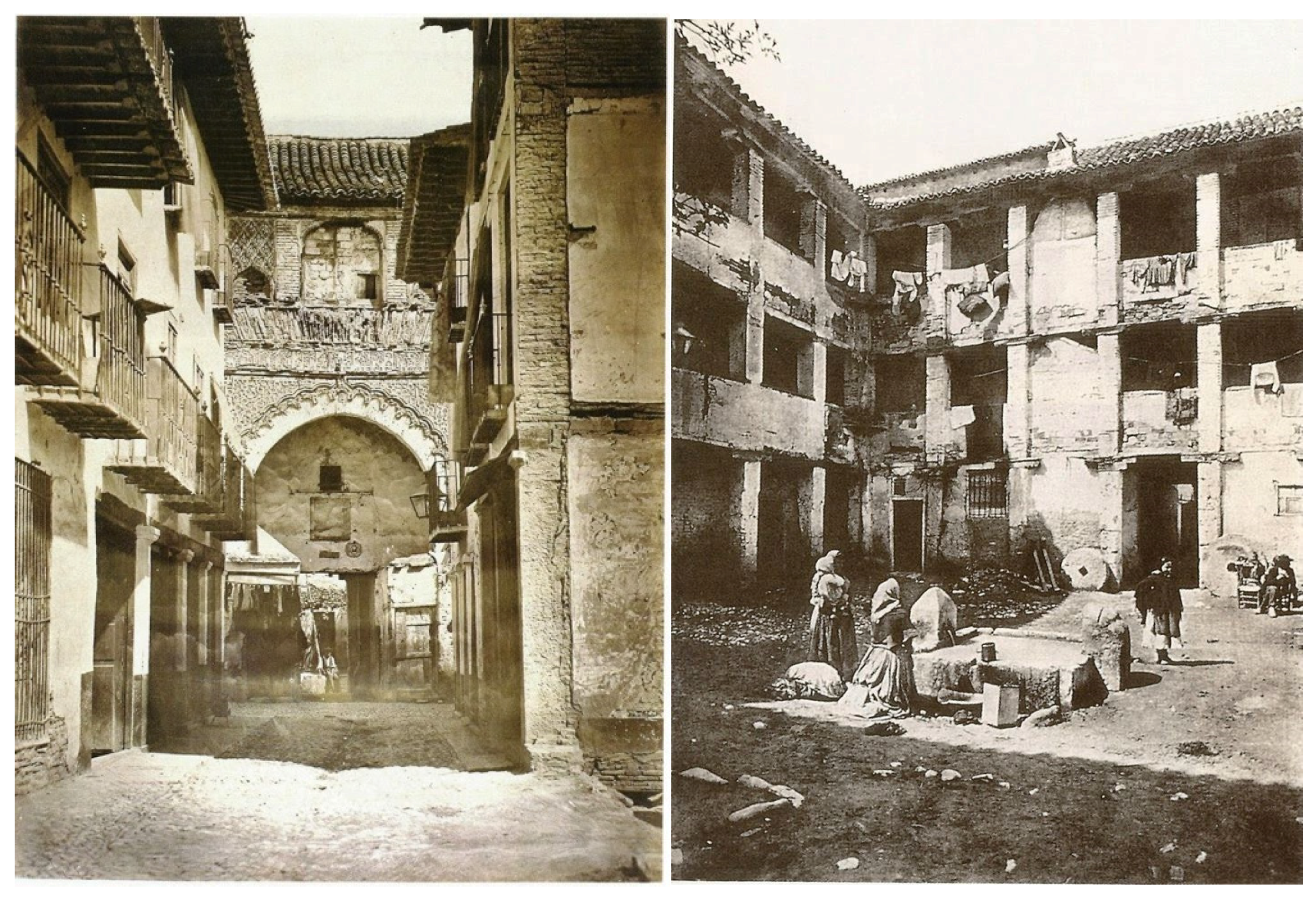
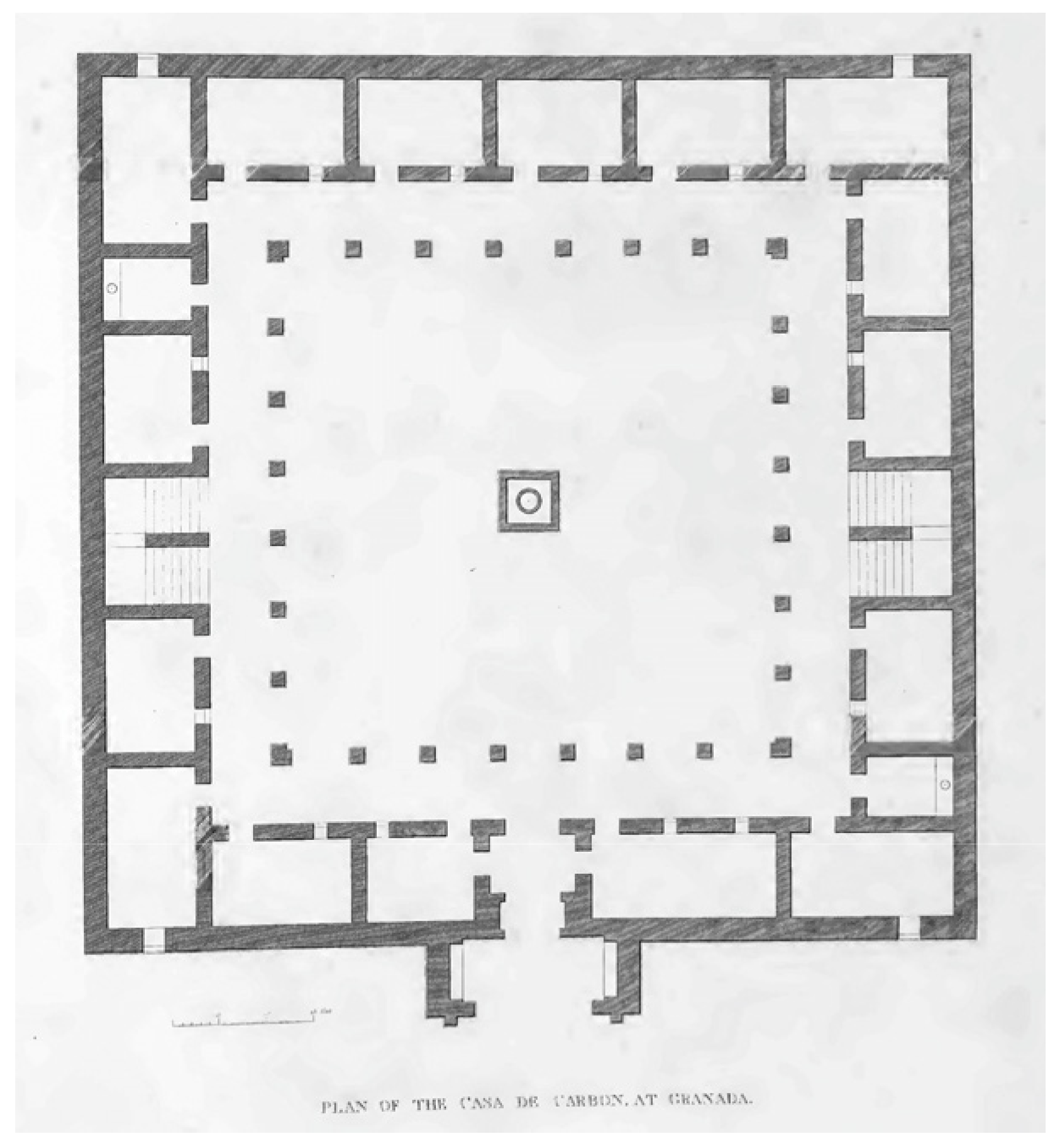
The shape of these buildings corresponds to a type imported from Persia and Syria to Spain. That is, the building, with a central courtyard, square or rectangular, had galleries supported by arches or lintels supported by pillars. To these galleries four bays circling the patio opened up the doors of the rooms in which they were divided. The ground floor was dedicated to warehouses and stables, while the upper floors were offered for lodging. [
26] With the Spanish reconquest, the
alhóndigas lost their function as inns and became warehouses and selling areas (
Figure 1).
The Corral del Carbón, was one of the three known
alhóndigas in Granada during the Nasrid period (13th–15th centuries) and is the only example of this building type still preserved in Spain [
25]. Most Spanish
alhóndigas were buildings of small size and poor construction, and therefore, despite being numerous in Islamic times, almost all of them have disappeared. However, the Corral de Carbón complex belonged to the wives of the Sultans of Granada, and after 1492 it was acquired by the Catholic Monarchs. Its royal origin presumably accounts for its exceptional size and the monumentality and decorative richness of its entrance gate, these features being unusual in this type of building (
Figure 2).
In 1531 this
alhóndiga was sold at a public auction [
28]. Until at least 1593 the building also served as the House of Comedies [
29]. To accommodate this new use, harrows would be built in the galleries of the first two floors (the latter being intended for women). The gallery above the other two floors had rooms that were turned into private boxes from which to view the show performed in the central courtyard [
29]. In the seventeenth century the building degenerated into a tenement house. Dwellings were located on the upper floors and the lower ones served as warehouses and stables for coal merchants.
In 1887 the Commission of Historical and Artistic Monuments of the province of Granada raised a request for the State to acquire the building, which then was privately owned [
30]. It was declared a National Monument in 1918, but it was threatened several times with demolition due to its poor state of conservation until 1928 when the architect Leopoldo Torres Balbás arranged for the monument to be purchased by the state with money from the entrance fees to the Alhambra [
31] (
Figure 3).
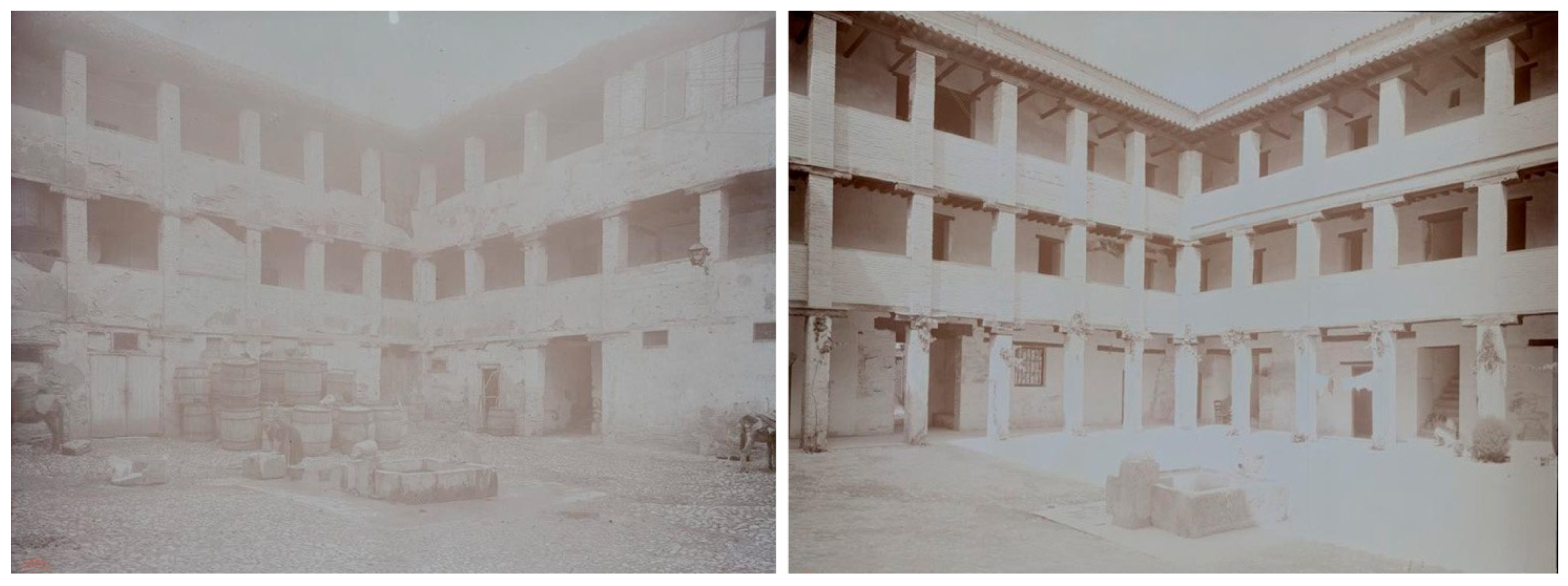
Torres Balbás drafted two restoration projects in 1929 and 1930 (
Figure 4 and
Figure 5). The first project included the demolition of the added parts as well as the removal and repair of the roof as well as almost all the floors, plus the repair of the courtyard pillars and certain interior walls. The second project continued the work begun in 1929, demolishing the modern staircase and reconstructing it in its original location, as well as some walls. The original floor was discovered in the courtyard and in the galleries, and the flooring of the rooms and the trim of the exterior walls were made.
In 1992 the building was restored by the architect Rafael Soler Márquez who made it the headquarters of the provincial office for the Andalusí Legacy Foundation, and for the Granada City Orchestra.
Its history demonstrates the capacity of building to be adapted to utilitarian purposes over the centuries, including theatrical performances and summer musical performances in modern times.
2. Materials and Methods
To survey the building, we used a laser scanner BLK360 and a total station TS02, both instruments from the Leica company, as well as a camera Sony Alpha 5000. The 3D point accuracy for the scanner was 6 mm at 10 m and 8 mm at 20 m given that specifications were one sigma (1 σ). The accuracy for the total station had an accuracy of 3″ in angles and 1.5 mm ± 2 ppm in measure distance. The specifications for the camera included a size sensor of 23.2 × 15.4 mm and a number of 20.1 megapixels mounting a 24 mm focal (expressed in 35 mm equivalent).
The scanning process covered the entire structure of the building (pillars, walls, floors, ceilings, and roofs), but when we needed a more detailed texture and metric images, we took photographs and computed their photogrammetric structure from motion (as in the case of the entrance gate).
2.1. The Scanning Process
Scanner quality refers to point density, which could be selected from low (one point every 20 mm), medium (one point every 10 mm), and high quality (one point every 5 mm). We used mainly the medium quality, the low quality was used for scanning the rooms, and the high quality was used for the mocarabe in the entrance.
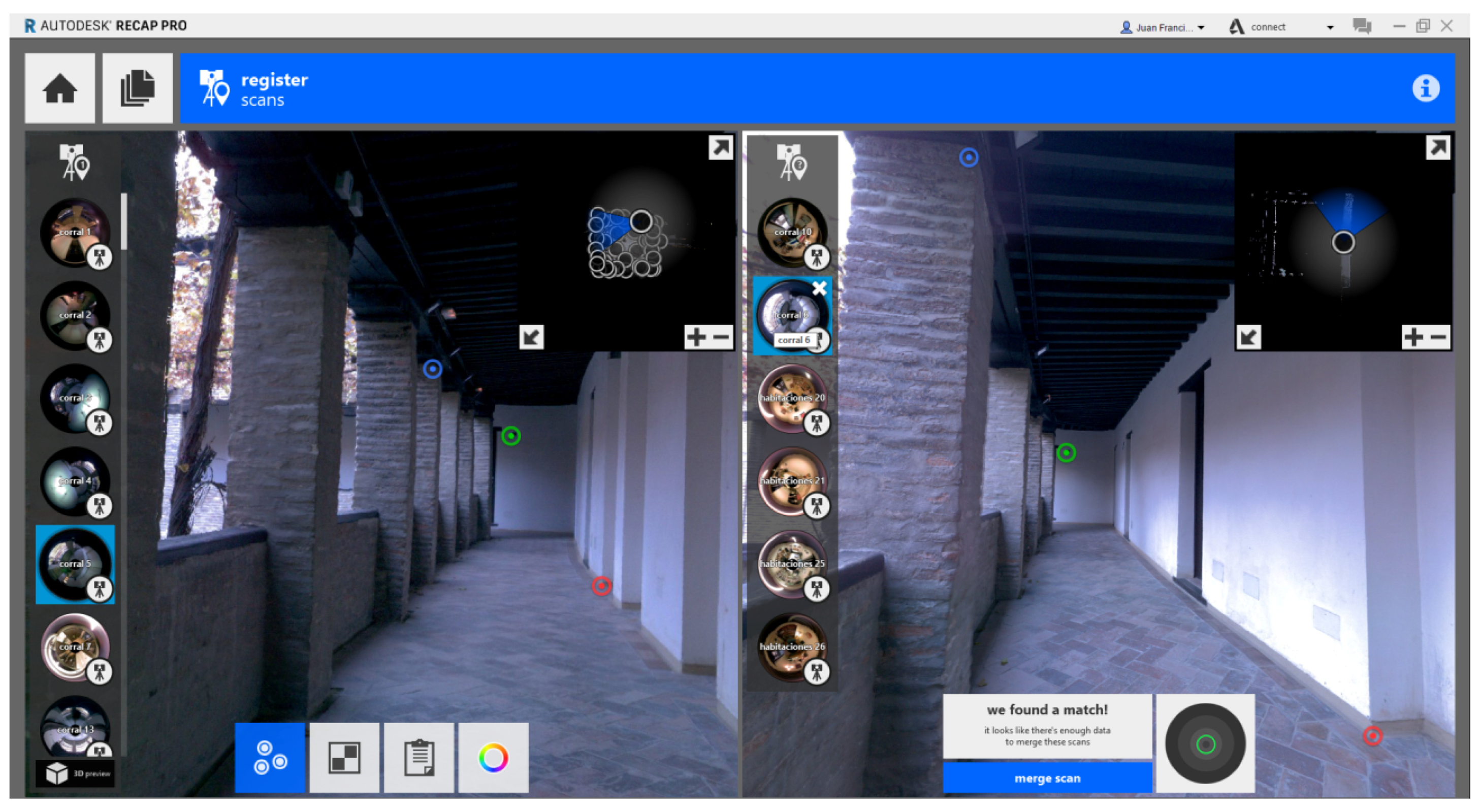
The registration process consisted of including every scan station in the same reference system, so that the final result was a point cloud defining the entire building. The registration could be performed in the field or in the office, and if the scan stations had enough and suitable overlap the registration was automatic. We performed the registration in the office to save time on the scan operations (we were time restricted in the Corral del Carbón so as not to interfere with tourist visits). Even in that case most the scans were registered automatically in the office but those of the rooms required manual identification of homologous points. Recap Pro was the software used for the registration process. When the scan is imported from the scanner, Recap tries to register automatically all the scans but if a scan cannot be matched then registration must be manual. For this, we had to identify three homologous points (red, green, and blue points in
Figure 6) between a reference scan (SREF; left screen in
Figure 6) and a scan to be registered (STBR; right screen in
Figure 6). When the match had good quality, a green circumference appeared in the right screen and we merged the STBR with the rest of the point cloud already registered (left screen). The scans already registered are represented by black circles (black square in the upper right portion of the left screen in
Figure 6).
When the quality was medium the circumference was yellow and the diameter larger than the green one and the quality parameters could be seen before merging the STBR (
Figure 7). When the matching was bad the circumference was red.
After each scan-station registration, we examined the report on the quality for such registration. The information referred to registration quality was: (a) overlap, which represents the percentage of STBR in common with the scan already registered and which is considered as the SREF; (b) balance is a measure which encodes the relative amount of the data in three orthonormal directions, indicating how much STBR registration has been constrained in the three orthogonal directions; and (c) points <6 mm indicates the percentage of points in the STBR that match the SREF with a difference of less than 6 mm.
Table 1 shows the quality parameters for a small sample.
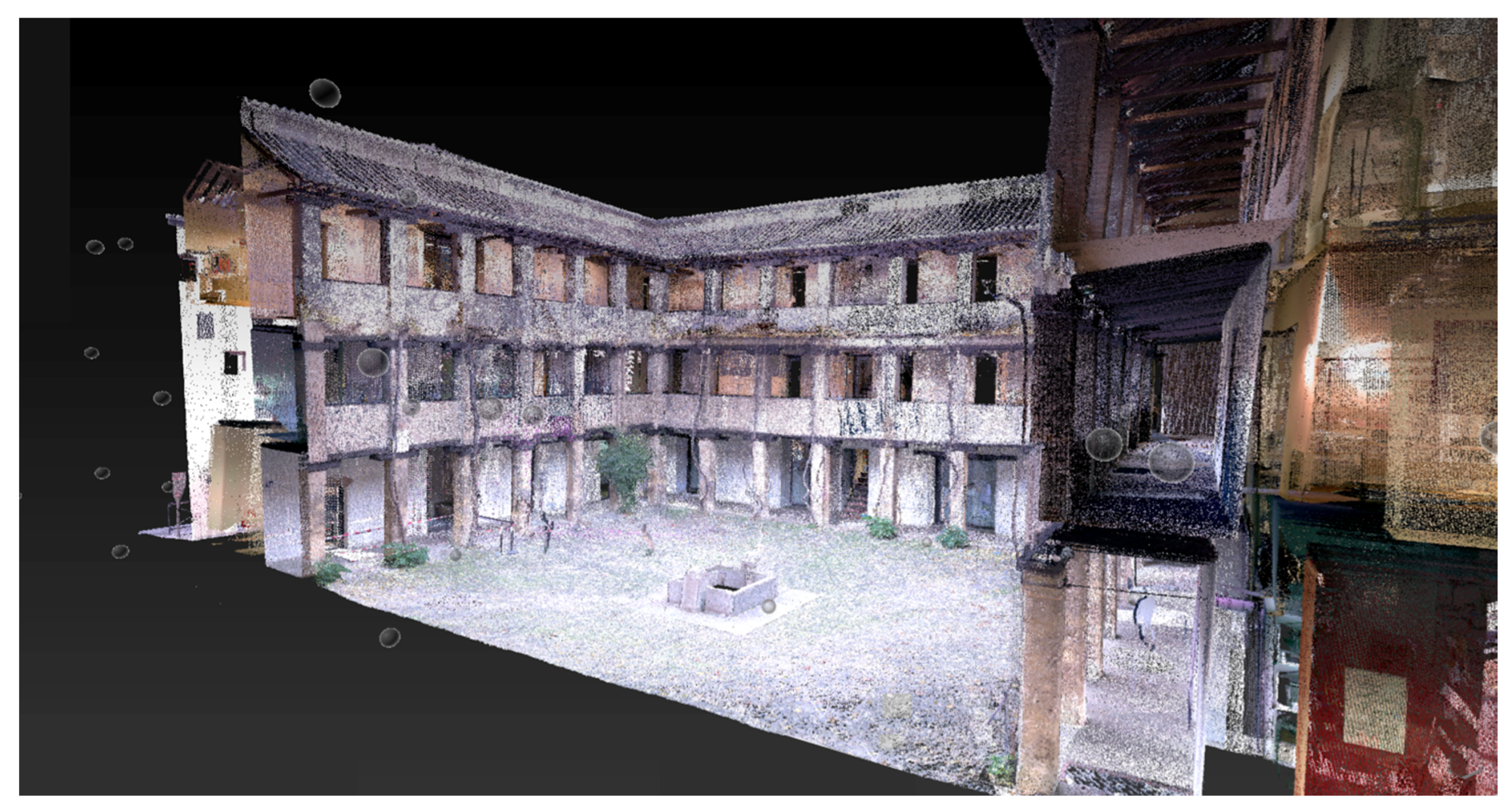
The Corral del Carbón survey consisted of 99 scan stations, some represented by gray spheres in the
Figure 8. The spheres are placed in the true spatial position where the scan stations were taken. The spatial distribution for several of the scan stations can be seen in
Figure 8, some of them camouflaged in the point cloud. In order to appreciate the structure and the level of detail achieved by the scan process, we show a vertical section from the Corral del Carbón in the
Figure 8.
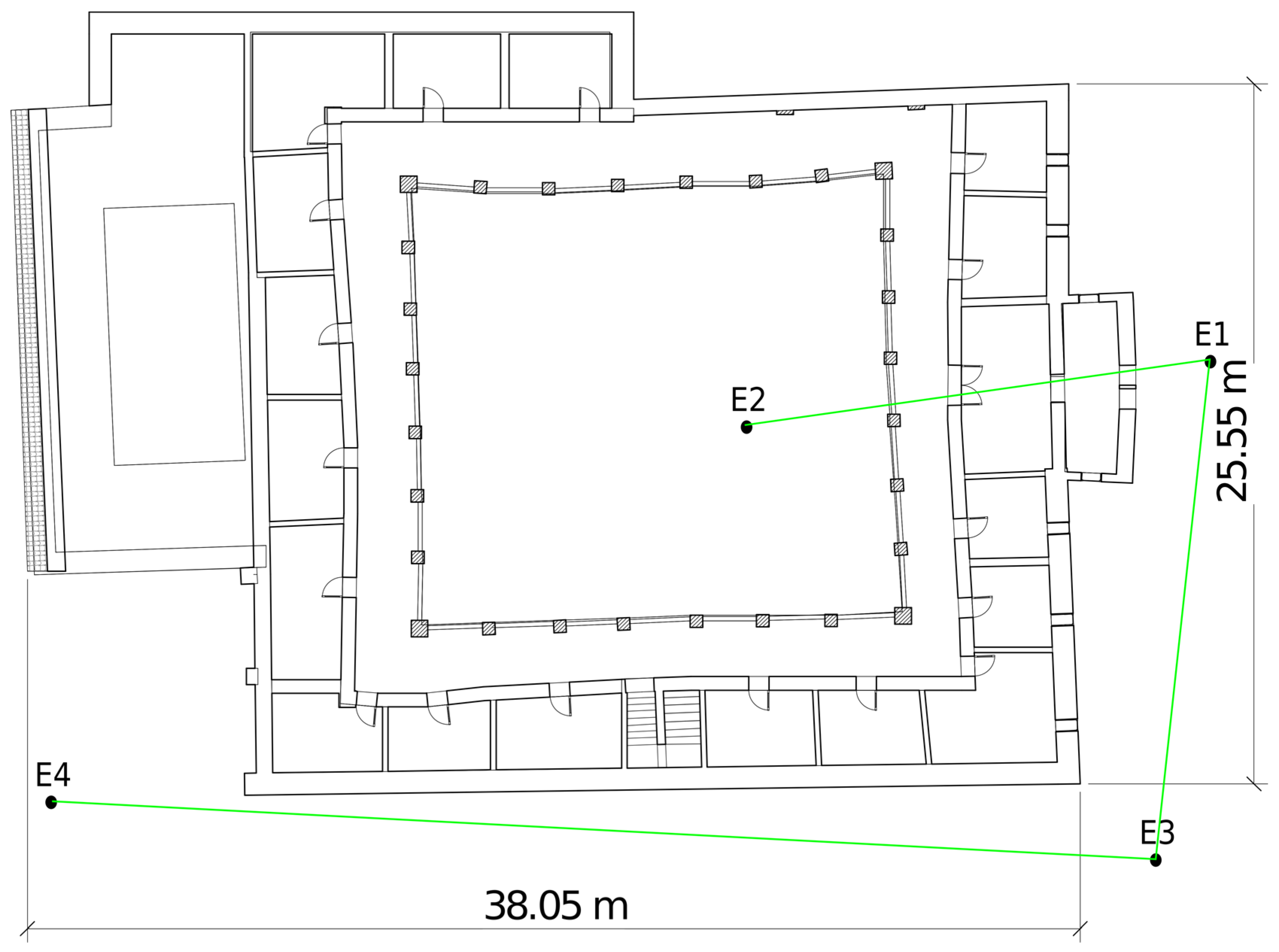
The BLK360 scanner did not have a level, so we needed a total station to level the entire building. We performed the leveling by establishing the coordinates for a bundle of targets spread throughout the Corral del Carbón courtyard. To check the scan-station registration accuracy, we used two traverses starting from the E1 station with 1 segment inside the courtyard and two exterior segments (E1–E3, E3–E4). The first scan station was taken inside the courtyard (near the traverse station E2) and the second scan was made near the traverse station E4. There were 6 intermediate scan stations (between the first and last one) in order to register the external walls. After the registration process, we computed the coordinates of six targets (
Figure 9) from the E4 traverse and compared them with the point cloud registered, and the mean square error was 5.3 mm.
2.2. The Photogrammetry Process
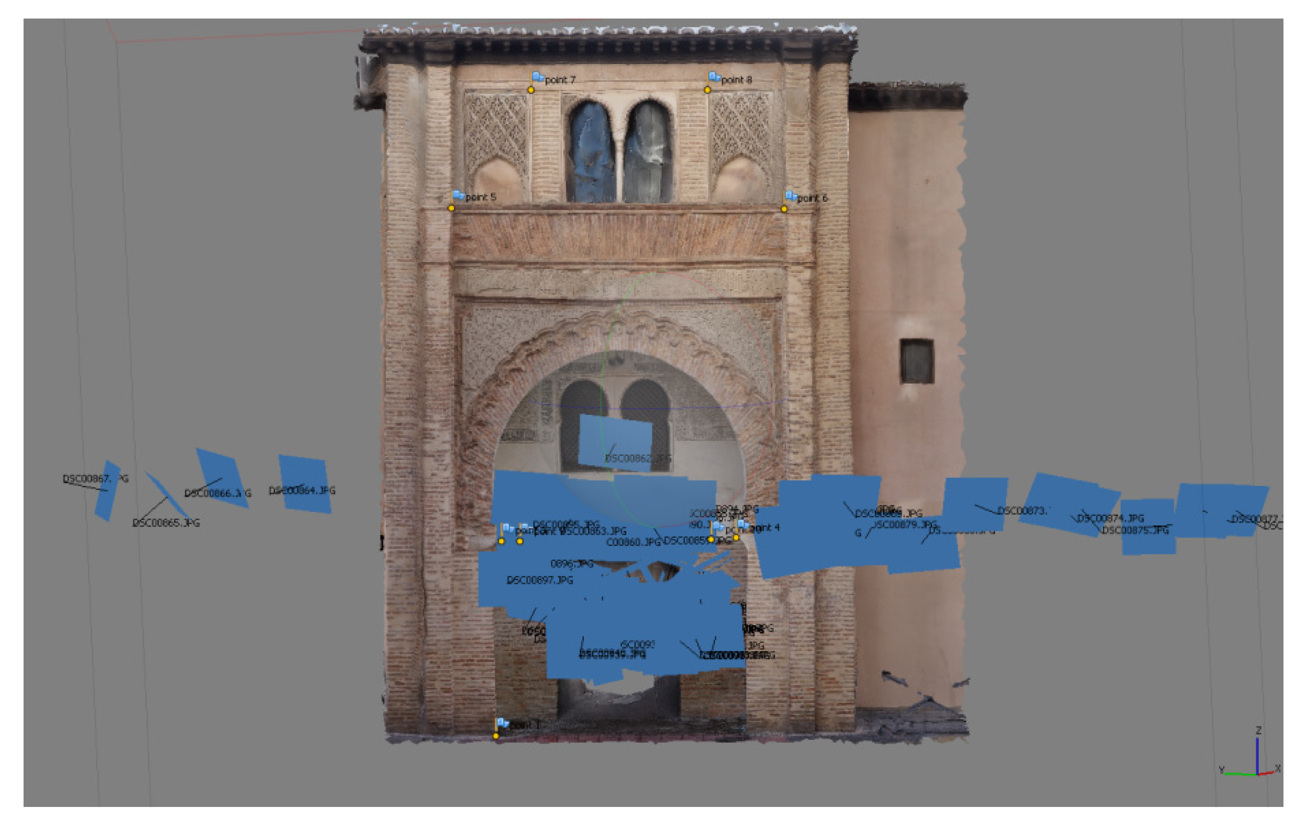
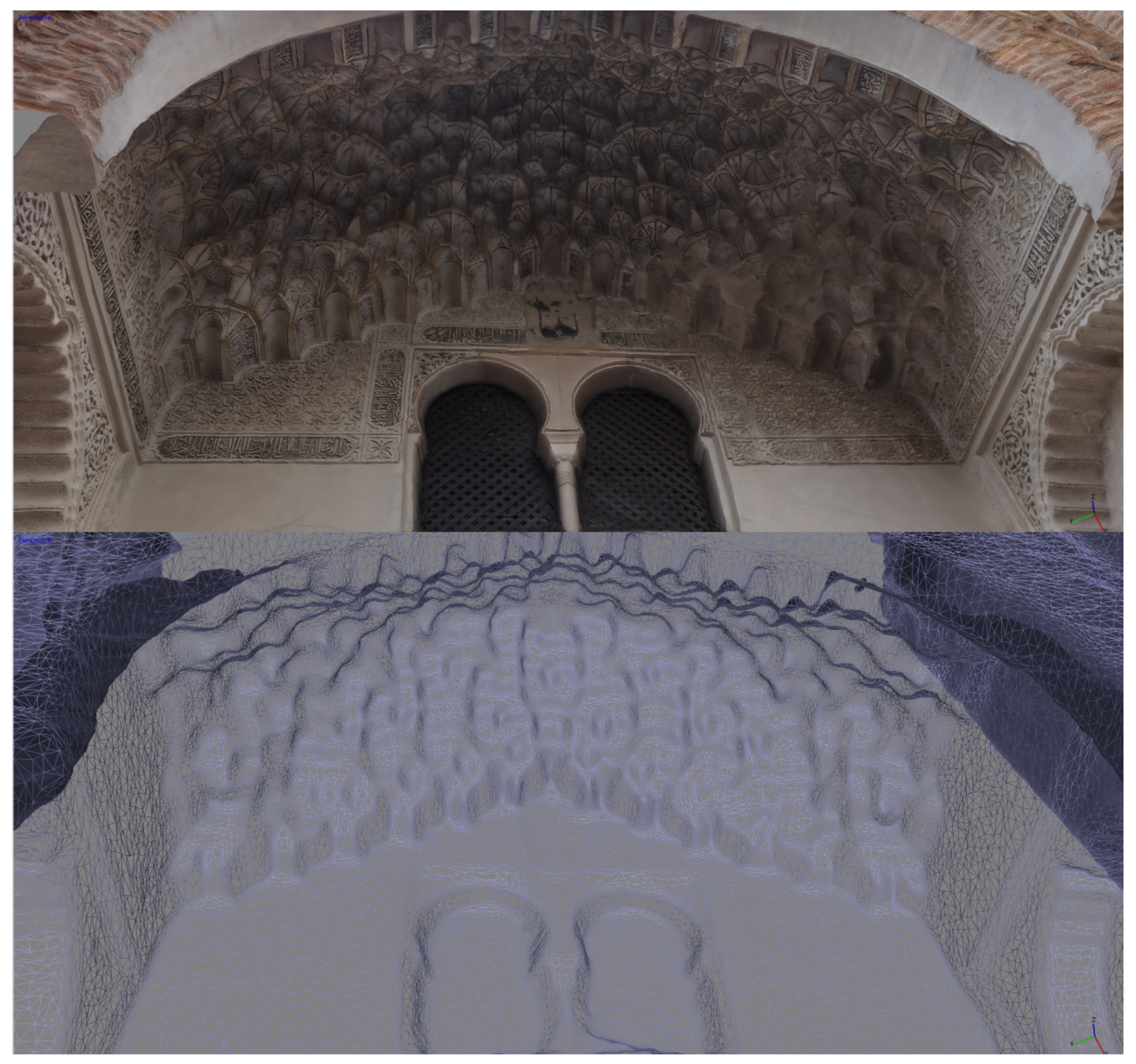
Photogrammetry was used to establish a more detailed textured mesh for the entrance facade, which has decorative geometric shapes in plaster and the mocarabe, widely used in the Nasrid architecture. The decoration has artistic and architectonic interest, so an accurate survey was made. We took 85 photographs for the reconstruction structure from motion (Sfm), some of them captured by the camera mounted on an extensible pole to a height of 5 m.
Figure 10 shows the Sfm distribution.
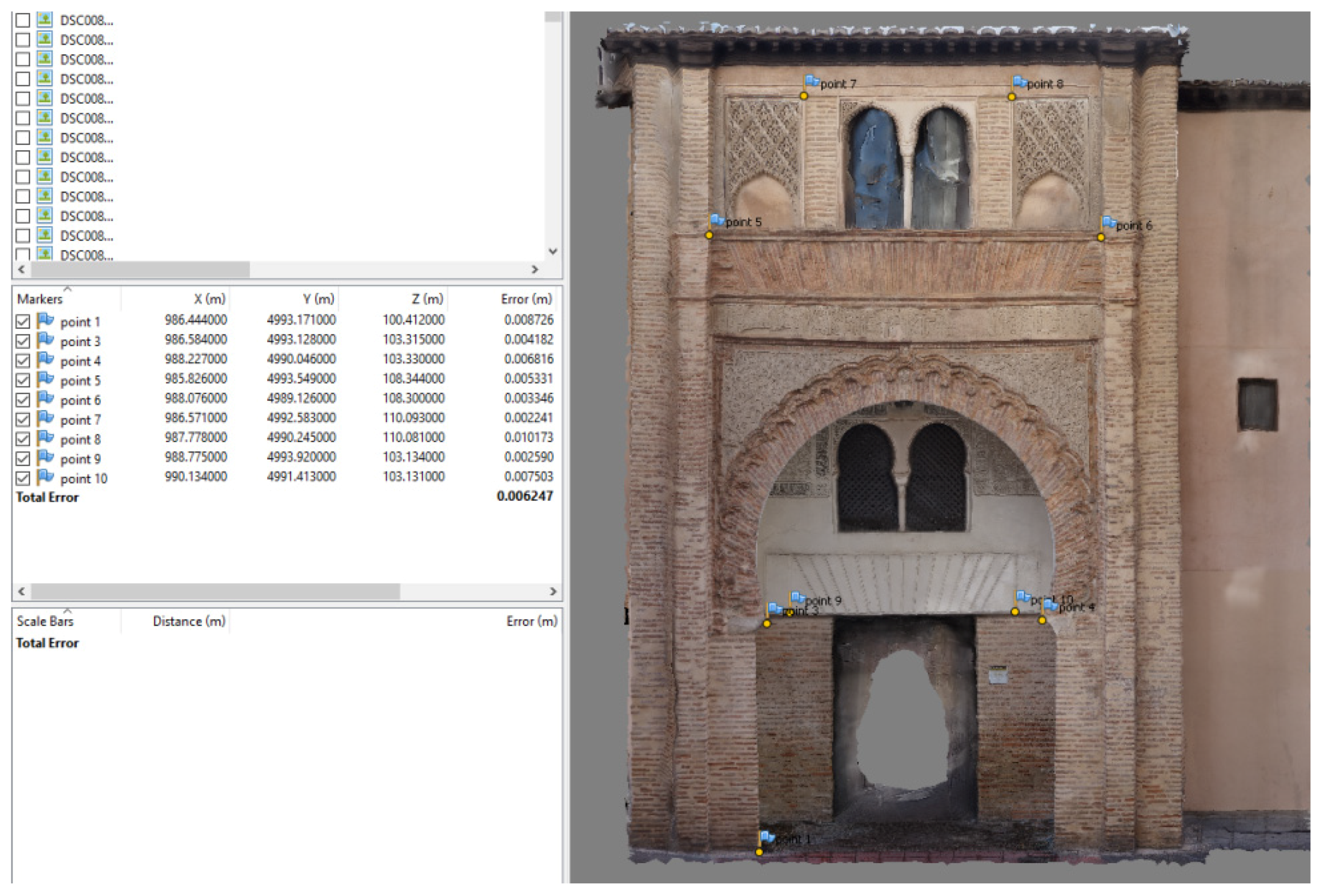
The facade mesh was scaled and leveled using the coordinates observed with the total station and fitting the homologous points by a least square computation. We have measured 10 control points on the façade (
Figure 11) from which the bundle adjustment was computed. The total error after the adjustment was 6.2 mm and it appears in
Figure 11, which has a suitable error for our accuracy requirements.
The most useful product, derived from the photogrammetry, was the orthophoto that allowed accurate measurements of major objects on the facade, e.g., the main arc, the twin arcs, the Arabic script, and the geometric features.
We used an additional product, derived from the photogrammetry performed on the entrance, consisting on the mocarabe mesh and its corresponding texture. For this product, we had to create a dense cloud, a mesh based on the point cloud, and finally the texture for the mesh. The whole process was performed by Photoscan software.
2.3. HBIM Methodology
Finally, from the point cloud generated by the scan registration process, we modeled an HBIM that is a comparison between point clouds and well-defined grammar of parametric objects meant to replicate the morphology of a building, in order to perform simulations or analyses on the abstract digital model. Our HBIM had a level of development 200 (LOD200). The LOD200 was defined by the BIMFORUM organization (the US chapter of the building SMART International) as follows: the model element is graphically represented within the model as a generic system, object, or assembly with approximate quantities, size, shape, location, and orientation. Non-graphic information may also be attached to the Model Element [
32].
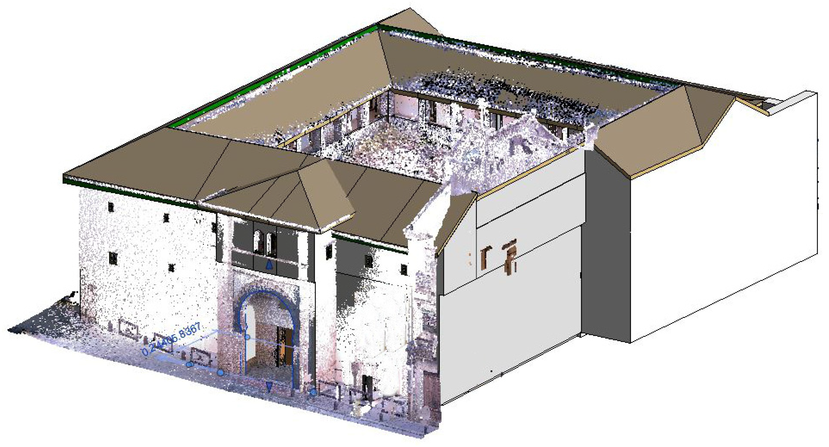
A BIM and therefore an HBIM can be broken down into three main sub-models: structural, architectonic, and MEP (Mechanical, Electrical and Plumbing). We focused on the structural and architectonic aspect of the building, because the structural state is a fundamental condition for its sustainability, while the architectonic features among the main targets in the conservation tasks. The MEP was not modeled in depth. Modeling a historical building with Revit has some limitations, for example, the walls allow only vertical construction, so we were unable to represent the frequent tilting deformations occurring in some walls. This constraint has to be mitigated adding some attribute to our model. An overlapping image between the HBIM and the point cloud is shown in the
Figure 12.
The first step consists of registering all the scans in a single point cloud, through Recap and exporting to the BIM software. The software used for modeling the Corral del Carbón as an HBIM object was Revit 2017, which imports in a natural way the scan files from Recap (“rcs” format).
Collaboration is an essential foundation in BIM workflow and it allows the simultaneous work of multidisciplinary teams in a central model.
By setting up the central model, multiple professionals can work on the same file without losing or overwriting information. This way of operating speeds up the workflow and allows shortening the time needed to complete the model. Once the model is created, the team members can work on the assigned levels, updating the information for everyone automatically. The BIM creation took 100 h (50 h for each of the two operators working in the collaboration mode).
The object to be modeled had a semantic meaning and we have segmented them according to their structural, architectonic, and artistic interest:
- -
Structural: walls, pillars, floors, beams and roof.
- -
Architectonic: parapets, windows and doors.
- -
Artistic: geometrical features on the entrance and mocarabes.
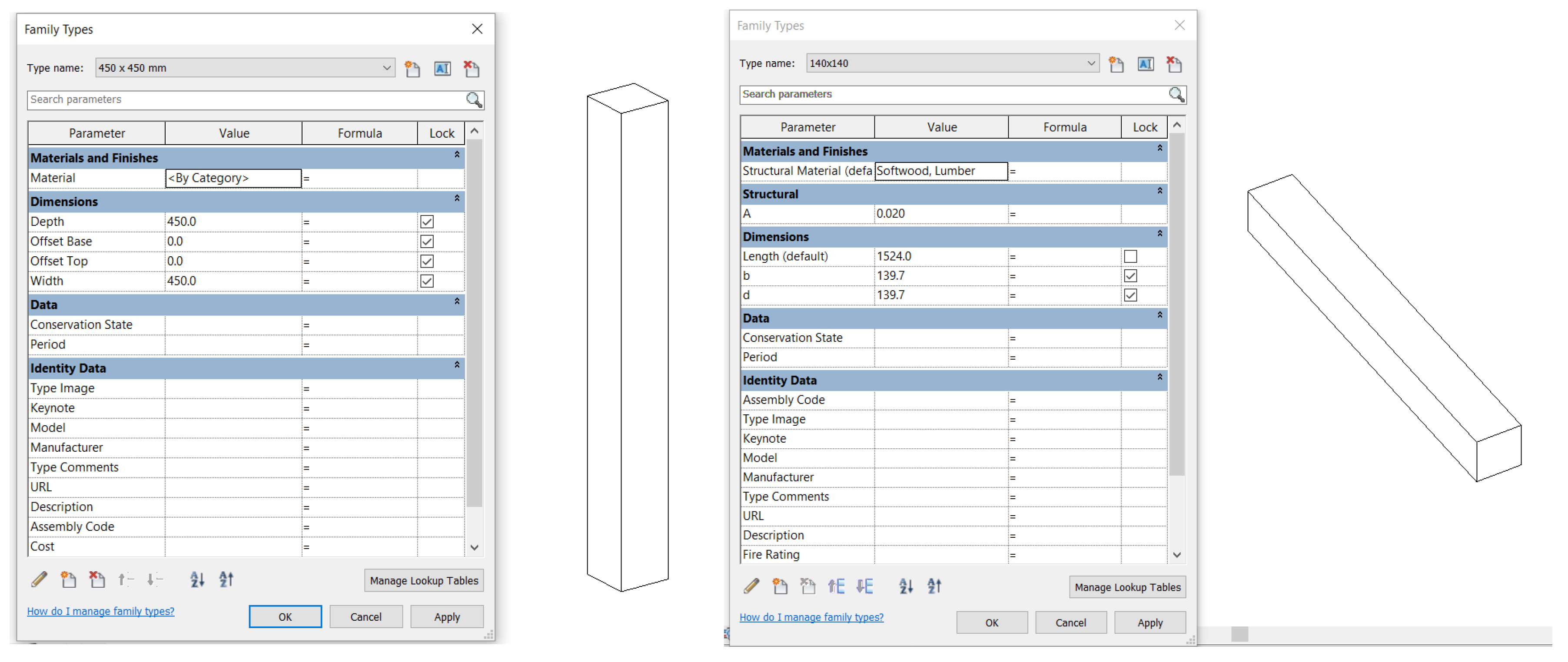
This model is not only geometrical, but also parametric since it is a database that contains all the information necessary. As it is a historical building, no elements in the software were suitable for the characteristics noted. This requires the creation of families for the elements that are identified from within the point cloud, which allow the reuse of geometries such as pillars, walls, and even elements such as doors and windows.
The
Figure 13 shows the creation of these families as a step prior to the architectural modeling of the point cloud.
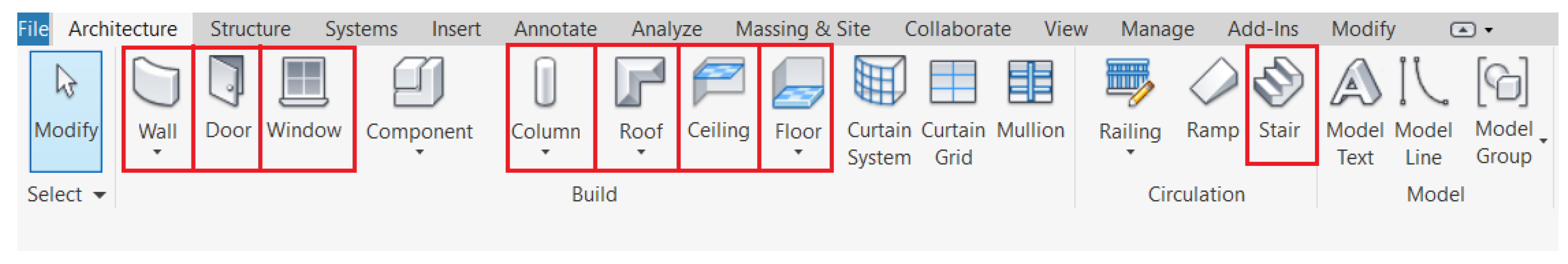
After identifying the elements and defining the families to be used in the HBIM model, we created the geometry using the tools provided by the software. The modeling was completed by floors, once the external volume of the building was defined, this being undertaken simultaneously by different members of the team.
The first task was to define the different levels and slabs of each element. The pillars and walls were the next elements to be modeled, continuing with the parapets, doors, and windows, as well as the stairs. This latter element was not previously existed as a family, since each element was modeled in situ as they were quite different. The last elements to be shaped were the ceilings, beams, and the roof. The tools used are highlighted in the
Figure 14.
The software used in the HBIM model had limitations, which did not allow a precise recreation of the model with respect to that presented by the point cloud, giving the model certain geometric simplifications. An example was the tilt of the walls, which had an angle that could not be represented in the model, being shown as totally vertical. To solve these problems, we created a group of parameters in each element to indicate the tilt angle.
3. Results and Discussion
The point cloud set composed of all the scans is a valuable database from which we can derive plans, views, sections and many graphic and analytical products useful for the making decisions linked to conservation and sustainability. The structure stability and the architectonic features are implicit in the scanned point cloud and we can model the building, according its necessities, using the suitable tools such as point cloud editors, CAD or BIM software.
One the most useful drawings we can derive from the point cloud is the floor plan, in
Figure 15 you can see the second-floor plan. We can compare this plan with those appearing in
Figure 1 and
Figure 4 corresponding to years 1815 and 1930, respectively. From the comparison, we observe how in the older plans the technicians drew a building simplification, i.e., they did not delineate the deformation in the courtyard perimeter. We can see how the edges of the galleries do not follow straight lines but convex curves towards the courtyard.
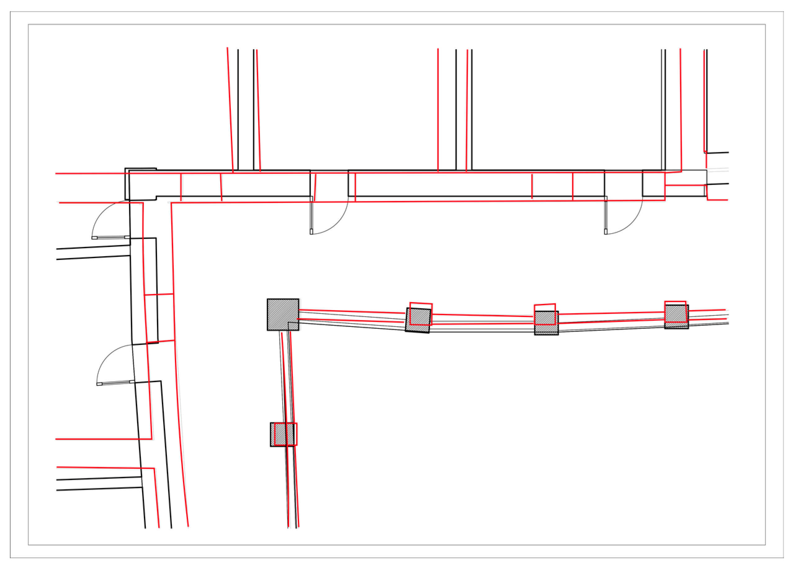
Gallery deformation is evident from the simple visual examination, but there are other structural aspects that are not so evident. For example, the footprint pillars from upper floors would be expected to coincide with those on lower floors, but
Figure 16 illustrates the opposite (pillars on different floors being misaligned). Similarly, structural walls located on different floors are not in the same vertical planes (we have drawn in red the pillars and walls located in first floor and in black the pillars and walls in second floor).
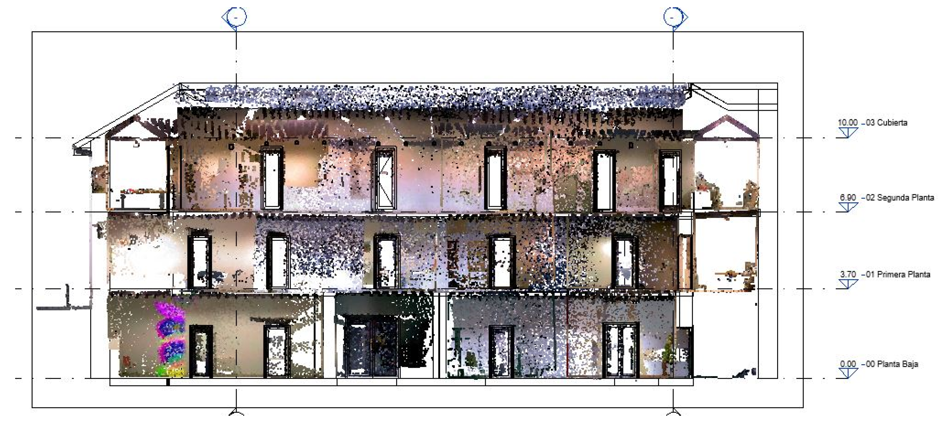
Key plans include elevations, which can be drawn accurately from the point cloud:
Figure 17 shows an example of an elevation plan where the levels have been included as objects in the HBIM using Revit.
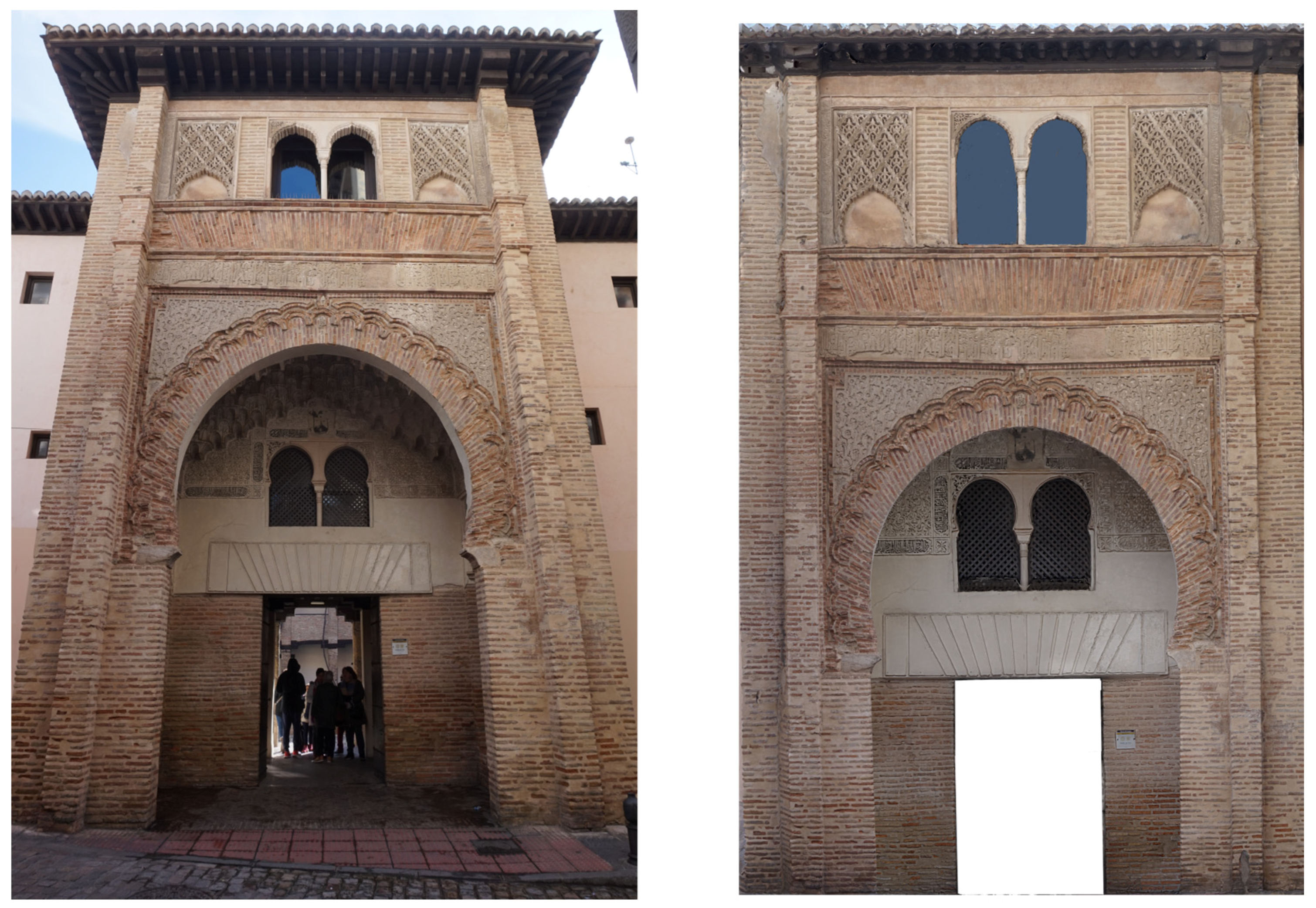
Although point cloud offers abundant details from the building, the scanner camera does not have a particularly high resolution (a sensor with 2592 × 1944 pixels); therefore, when we need certain features with more detailed textures, we have to perform photogrammetric procedures. Here, we used photogrammetry to reconstruct the 3D structure from the Corral del Carbón entrance gate (
Figure 18 and
Figure 19). We sought to establish the accurate dimensions and conservation state of the architectonic features comprising the entrance facade. We can discern (
Figure 18) how the deformation linked to a perspective view is eliminated in its corresponding orthophoto, which has been derived from its photogrammetric reconstruction. The orthophoto is a valuable graphic document because the measures extracted from it reproduces the real dimensions and geometry of the architectonic features, which could be used in the future for conservation and restoration tasks.
The mocarabe is one of the most representative elements in the Nasrid architecture, so a detailed 3D representation would be fundamental in studying their characteristics: metric properties, distribution, shapes, and images and pigment on it. The most suitable technique would be the photogrammetry because it can reconstruct an accurate 3D mesh and also because provides detailed texture, allowing an optimal interpretation. Therefore, we recreated the mocarabes in the entrance using photogrammetry (
Figure 19).
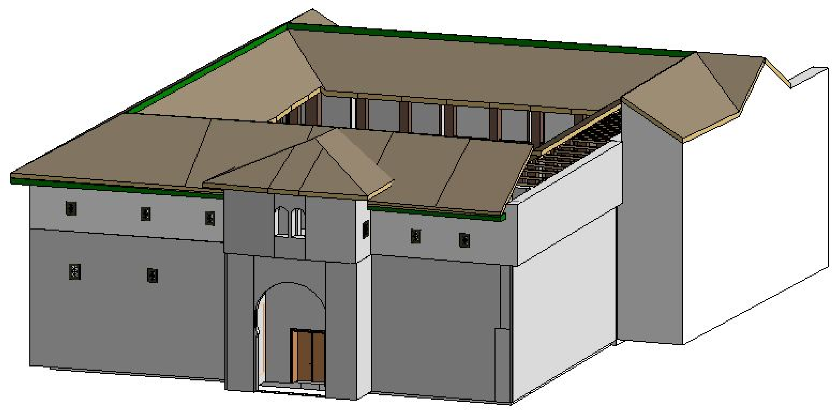
The complete Corral del Carbón HBIM, modeled according a LOD200 specification, appears in
Figure 20, displaying windows, doors, roof, pillars, arches and details such as the beams under the roof.
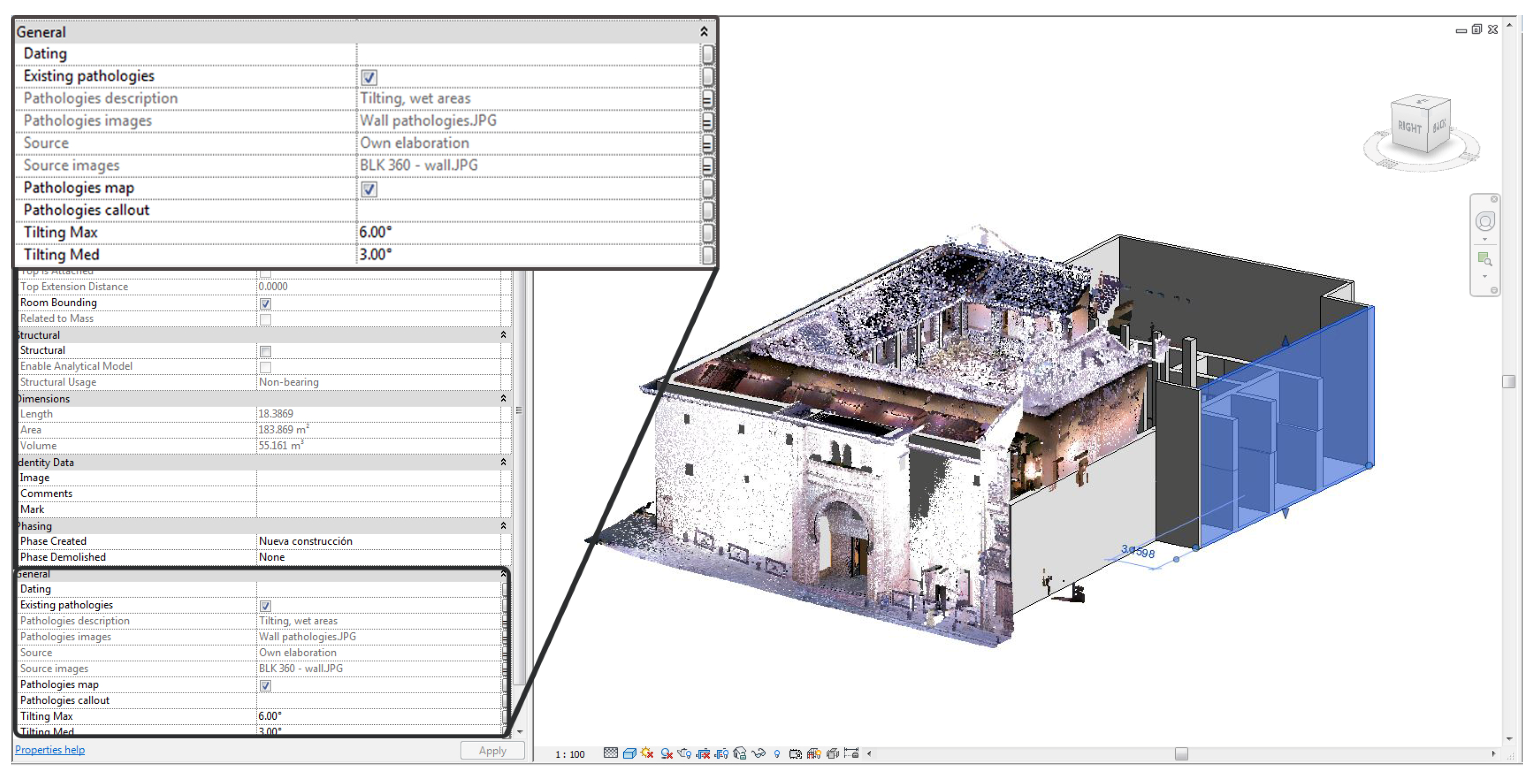
As explained in the Methods section, an HBIM is usually composed of three submodels: structural, architectonic, and MEP. In the structural cases, the BIM software lacked a tool for modeling deformations, particularly the tilting of some walls. Such tools would be necessary in HBIM for structural issues. Hence, we extended the building information by adding some attributes to the structural submodel (
Figure 21).
We added the Tilting Max and Tilting Med attributes to indicate the maximum and medium values for any wall tilting. Additional information of interest for later restoration and conservation tasks included pathologies, so we included attributes such as a Pathology description, Pathology map and images where the pathologies are represented.
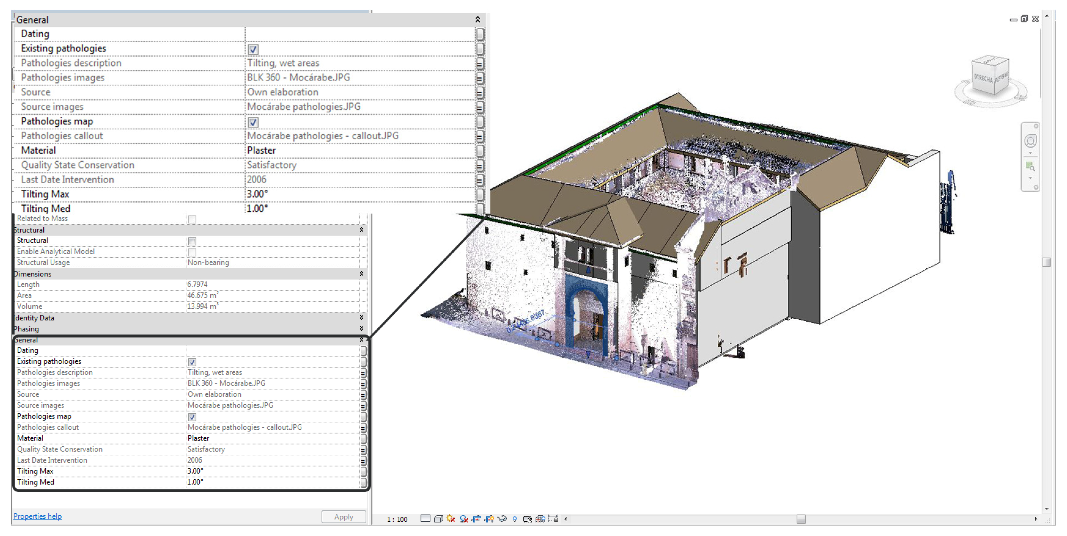
Following the same idea of including some attributes in the structural submodel, we added new attributes to the architectonic submodel (
Figure 22). In this case the architectonic element of interest was the entrance arch, which bears geometric features and Arabic script in plaster. Because their importance in terms of aesthetic value and cultural heritage, we established attributes referring to their conservation status and last date they were restored. As in the structural submodel, pathologies were part of the attributes list.
The above explanation and discussion of the results can assist in the conservation of the Corral del Carbón, so that it can accommodate functional activities in a sustainable way: tourist visits, headquarters of the Provincial Delegation of Culture of the Government of Andalusia, headquarters for the Legado Andalusí Institution where permanent exhibitions are held; headquarters for Granada Jazz Festival organization, Granada City Orchestra association; and an office of the Alhambra Trust.
4. Conclusions
Given that the description of a Cultural Heritage monument is not complete without historical documentation, we started our research with the history of the Corral del Carbón, its origins and its functionality down through the centuries. The study in this paper shows how surveying and modeling can aid conservation tasks in Cultural Heritage buildings to ensure sustainable activity. The techniques used for the surveying were the scanner laser to recreate the entire structure for the building, and photogrammetry in order to document relevant architectonic elements in a more detailed way. For the modeling, we used specific BIM software until establishing an HBIM. Once the model was built, we determined the magnitude of the deformations. Some of these were clearly visible (curved walls and tilting pillars and walls), whereas others were not so evident (misaligned pillars and walls). The HBIM creation process required features that the BIM software lacked, such as the ability to model tilting walls or variable sections, but such constraints can be mitigated by adding new attributes. Nevertheless, most of our HBIM was defined in an architectural mode using BIM families, created for the key objects: pillars, walls, beams, roofs, floors, doors, and windows. Our HBIM offers the user many benefits for managing tasks in order to undertake restorations and conservation or even structural studies (the model could be used as the base to establish the physical parameters needed in the structural computation). Our study shows how the workflow of surveying and modeling can build an HBIM that later will facilitate conservation tasks and will allow monuments such as the Corral del Carbón to continue their activities in a sustainable way.

 ,
, 


