Article

A Study of the Large Deformation Mechanism and Control Techniques for Deep Soft Rock Roadways

1
State Key Laboratory of Geomechanics & Deep Underground Engineering, China University of Mining & Technology, Beijing 100083, China
2
School of Mechanics and Civil Engineering, China University of Mining & Technology, Beijing 100083, China
3
State Key Laboratory of Mining Disaster Prevention and Control Co-founded by Shandong Province and the Ministry of Science and Technology, Shandong University of Science and Technology, Qingdao 266590, China
4
Department of Resources and Civil Engineering, Shandong University of Science and Technology, Tai’an 271000, China
*
Authors to whom correspondence should be addressed.
These authors contributed equally to this work.
Sustainability 2018, 10(4), 1100; https://doi.org/10.3390/su10041100
Submission received: 6 March 2018 / Revised: 30 March 2018 / Accepted: 4 April 2018 / Published: 6 April 2018

Abstract

:
Large deformation control of deep soft rock roadways has been a major problem in mining activities worldwide. This paper considers the supporting problem related to large deformation of a deep soft rock roadway in Chao’hua coal mine. The discrete element simulation method (UDEC software) is adopted to simulate a tailgate of panel 31041 in Chao’hua coal mine. The failure patterns of unsupported and primary supported roadway are simulated, and these reveal the characteristics of deformation, stress and crack propagation. The excavation of roadway leads to high deviator stress, which exceeds the peak strength of shallow surrounding rock and causes it to enter the post-failure stage. Tensile failures then initiate and develop around the roadway, which causes the fragmentation, dilation and separation of shallow surrounding rock. The compressive capacity of the primary support system is low, which results in serious contraction in the full section of the roadway. An improved control scheme is put forward for the support of a tailgate. The underground test results confirm that the improved support system effectively controlled large deformation of the surrounding rocks, which can provide references for support in the design of roadways excavated in deep soft stratum.

1. Introduction

The rapid development of the world economy and society causes huge resource consumption, which dries up the shallow mineral resources and causes the mining for resources to progress continuously more deeply into the earth [1]. At present, the main mining countries have entered the deep mining stage. The mining depth of more than 100 mines exceeds 1000 m, most of which are distributed in Russia, Poland, South Africa, Canada, the United States, India, Germany, and China [2]. The rock types of a considerable number of the mines transform from the shallow hard rock to the deep soft rock, and the support problem of soft rock is very serious [3]. The support theory and technical system formed in shallow mining engineering has been partially or seriously invalid in deep mining engineering [1]. In deep mining engineering, the deformation state of rock mass transforms from the shallow linear elastic small deformation to the deep nonlinear large deformation [3]. The related support problems cannot be solved by the existing support theories and control measures, but must be solved by seeking stability control theory and technology that conform with large deformation failure characteristics.
Coal is one of the most important foundational resources, accounting for 30% of the world’s total energy consumption [4,5]. Nearly 60% of china’s discovered coal resources are buried deeper than 800 m. The mining depth is growing at a rate of 10–25 m per year [6], and the average coal mining depth has reached about 700 m [2]. Underground coal mining mostly adopts the longwall mining method [7]. In this method, transportation and ventilation roadways need to be excavated on both sides of mining panel. Statistics indicate that roadways excavated in deep soft rocks account for approximately 30% of the annual total excavation, but the repaired deep soft rock roadways during excavating account for 70% [8]. The deep soft surrounding rock mass usually has a low uniaxial compressive strength between 0.5 and 25 MPa and suffers from high in-situ stress. These characters result in large rheological deformation in all directions of the roadway cross section [9]. Furthermore, many improper support schemes with the planned supporting cost could not resist large rheological deformation, which leads to a series of roadway instabilities and loss of function for transportation and ventilation [8]. Repair and re-support of soft rock roadways have to be conducted constantly in cases where roadway closure is severe to maintain its cross-section until mining activities are finished [10]. This causes enormous economic loss, delay of mining activities, and serious potential safety risks [11]. For sustainable exploitation of coal resources with increasing buried depth, it is necessary to control the stability of deep soft rock roadways. To achieve this, the large deformation mechanism of soft surrounding rock interacting with existing support under high in-situ stress needs to be revealed and proper support must be provided.
The existing support patterns of soft rock roadway can be classified into two types. (1) Passive rigid support such as U-shaped steel sets [12,13]: this support type is thought to provide high supporting resistance and large shrinkable ability to control the stability of deep soft rock roadways [12,14]. However, the support materials are expensive and difficult to install and remove [10]. Moreover, this support pattern is passive; it cannot apply pretention and confining pressure to inhibit the bed separation in a timely manner. (2) Active flexible support such as bolts and cables [15]: this support pattern is economical and easily installed [9]. As an active support pattern, the pre-stress applied on the installed rock bolts and cables creates a confining pressure on the shallow surrounding rock immediately after installation, which increases the frictional strength along bedding planes and joints [16,17,18]. In addition, loose blocks or thin stratums can be compressed into an integrated beam which is more resistant to bed separation and bending [19,20]. However, the elongation of rock bolts is too small to control the large deformation of surrounding rock and the anchored effects are poor and pretension is low due to the low strengthen and fragmented, swelling soft rock.
Field applications have indicated that a single or simple support method was too weak to resist the large rheological convergence in deep soft surrounding rock [8]. To solve this supporting problem, the combined supporting methods are essential. For example, the simple “U-steel arch+ shotcrete” support was installed to reinforce the longwall entries of Chao’hua coal mine. As the tailgate was excavated, support materials were immediately installed, but significant surrounding rock deformation occurred several meters behind the advancing face and the excavation of the roadway was postponed. To solve this problem, this paper presents a case study on failure mechanism and support techniques of deep soft rock roadway. A numerical simulation with UDEC is undertaken to reveal the stress, deformation, cracking and dilation states of soft surrounding rock, and an improved “bolt-cable-mesh + shell” support pattern is finally presented and evaluated to support the soft rock roadway.

2. Geomechanical Properties of the Studied Deep Soft Rock Roadway

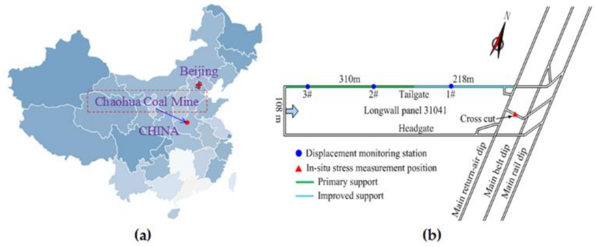
2.1. General Situation of the Studied Mine

Chao’hua coal mine is located in Zhengzhou City, Henan Province, China (Figure 1a). The depth of the longwall panel 31001 varies between 800 and 850 m. The layout of roadways is shown in Figure 1b. The surrounding rocks of the tailgate are mainly composed of coal seam and mudstone, and the detailed stratum column is described in Figure 2.

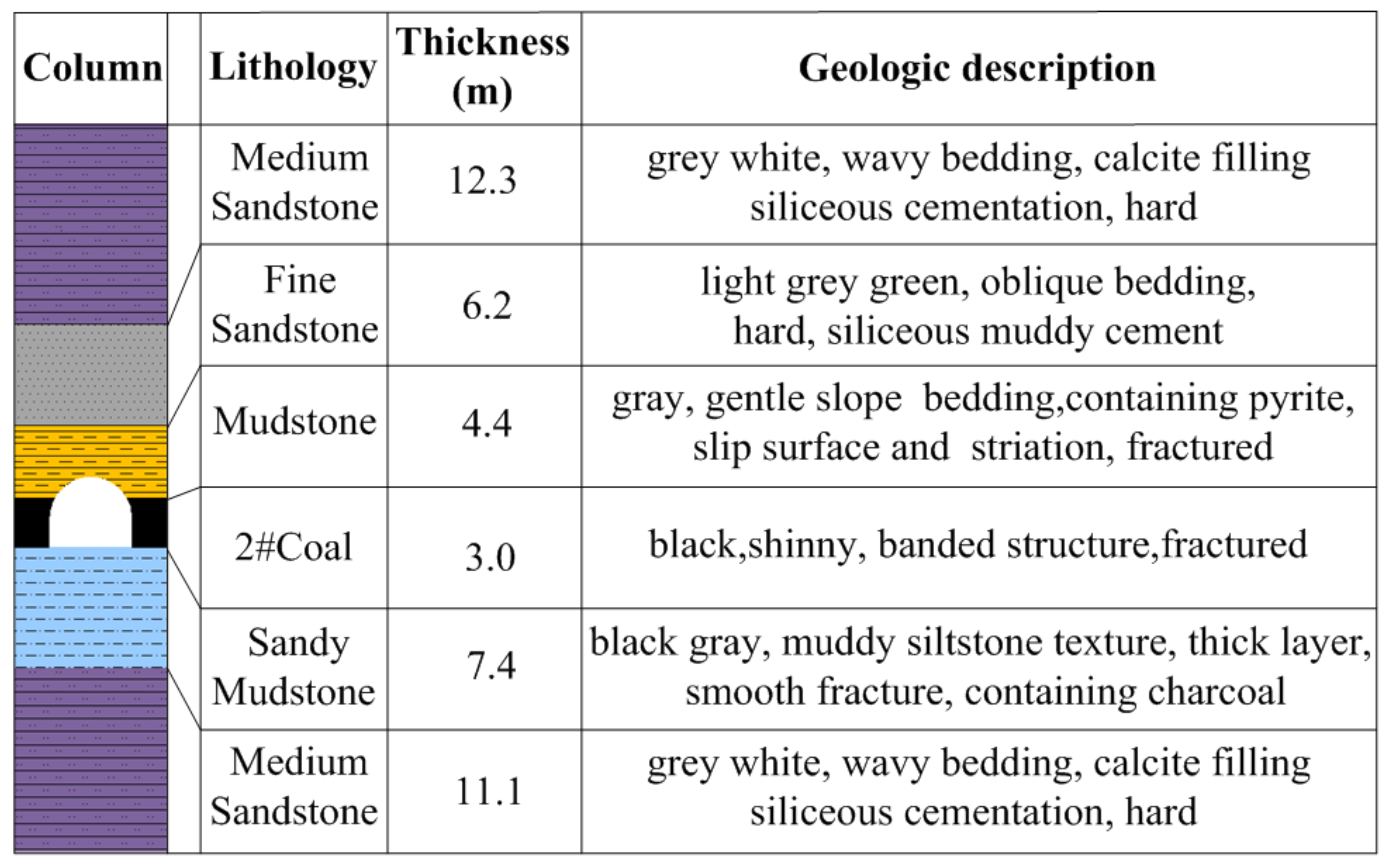
2.2. Physical and Mechanical Properties of Engineering Rock Mass

In situ stress measurement, intact rock properties measurement and optical televiewer imaging had been implemented in the in situ tests. The in situ testing borehole was vertical and located in the main dip close to the longwall panel 31041 (Figure 1b), which was 15 m in length and 50 mm in diameter. The in situ stress was measured using the stress relief method [21] and the results were σH = 20 MPa, σh = 18.27 MPa, and σv = 32.15 MPa. The direction of σH was N 122° E. For rock strength measurement, laboratory tests with the ISRM recommended standard [22] were established on different types of rock samples obtained from the surrounding rock masses of the tailgate. The uniaxial compressive strength and Young’s modulus rock samples were obtained from uniaxial compression tests in the laboratory. The intact rock properties are listed in Table 1.
The strength of the rock mass was reduced due to the discontinuity (such as joints, cracks, and bedding). Thus, it is essential to discount the intact rock parameters. Zhang and Einstein summarized the field test data and conducted a fitting study in which they derived the following correlation between rock quality design (RQD) and the ratio of rock mass deformation modulus to intact rock specimen [23]:
E m E r = 10 0.0186 R Q D 1.91
where RQD values of the rock masses were evaluated from borehole televiewer images.
Singhand and Seshagiri analyzed the field and laboratorial data, and obtained the following correlation between the ratio of rock mass uniaxial compressive strength to rock specimen and the ratio of rock mass deformation modulus to intact rock specimen [24]:
σ cm σ c = ( E m E r ) q
where σc and σcm are the uniaxial compressive strength of an intact rock and a rock mass, respectively. q was set to 0.67 [24]. The scaled rock mass properties are listed in Table 1. The tensile strength of the rock masses was estimated to be one-tenth of the compressive strength.
The rock mass strength values suggested that the surrounding rocks were typical soft rocks, generally of low and poor quality. Borehole optical televiewer imaging revealed that the fractures heavily developed in the roof. The annular fractures that developed in the borehole indicates that roof separation may have occurred in the shallow area, and the integrity of rock mass gradually increased from shallow to deep areas (see Figure 3).

2.3. Large Deformation Characters of Deep Soft Rock Roadway

The cross-section shape of the roadway is a straight wall semicircular arch, with width and height of 5.14 m and 4.37 m, respectively. The primary support system was made up of “U-shaped steel +shotcrete”. By field investigation and monitoring in the tailgate, the deformation and failure characteristics of the longwall panel 31041 tailgate are summarized as follows:
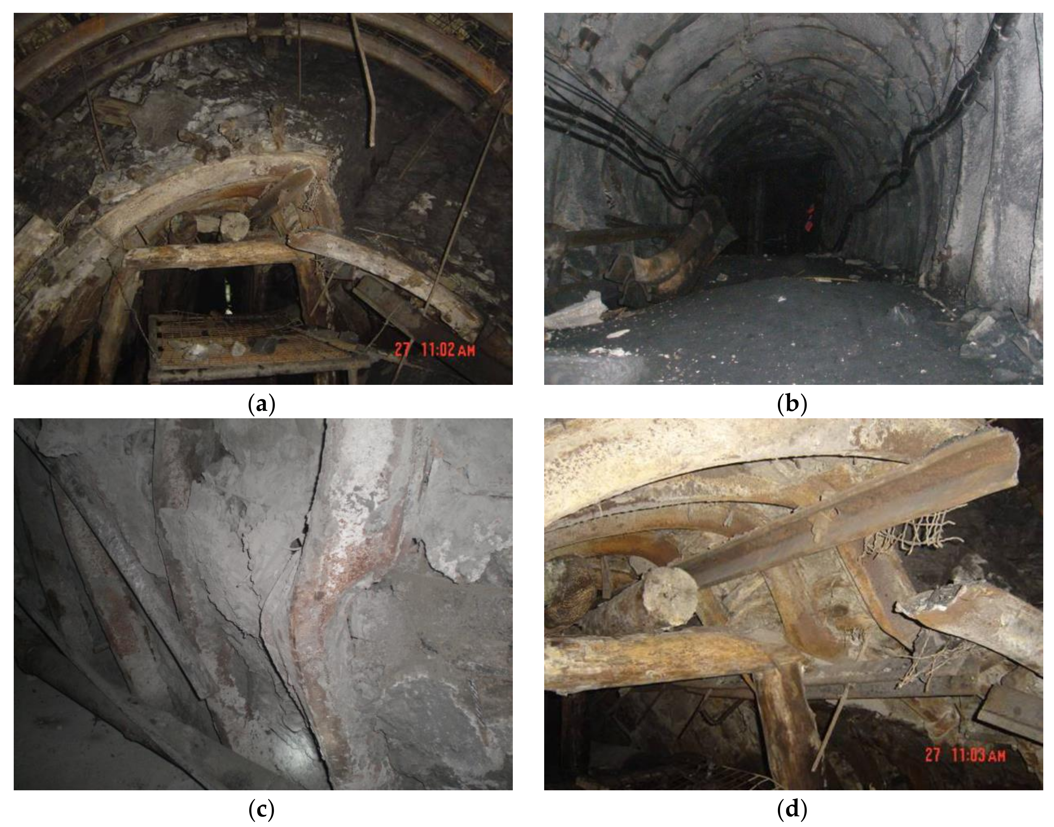
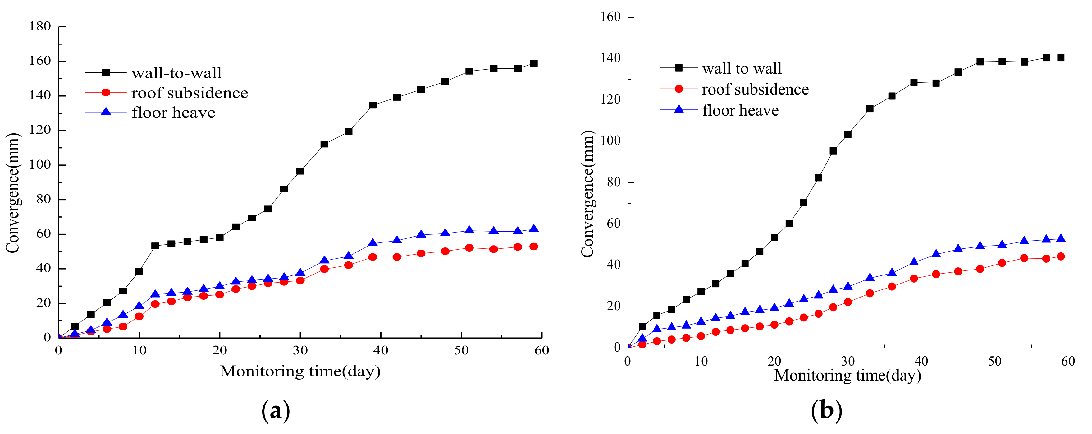
  • Large and long-term duration deformation in surrounding rock. After the roadway was excavated, significant deformation occurred in a few days. Skin roof falls and sides spalling made it difficult to obtain the roadway cross section using the road header. The large deformation continued to occur even after U-shaped steel sets were installed, sides were extruded toward the free surface and shrinkage appeared (Figure 4a). Roof subsidence occurred due to stagger and swelling in roof stratums (Figure 4a); Serious floor heave appeared in some places (Figure 4b). Moreover, the phenomena of side shrinkage, roof subsidence and floor heave continued for a long time, which resulted in an extremely weak stability of the surrounding rock. The convergence rate of the roadway was as high as 5–10 mm/day and lasted for 2–3 months, which indicated the potential for an unexpected roof fall and rib spalling. The final reduction percentage of the roadway cross-section could be 30–60%.
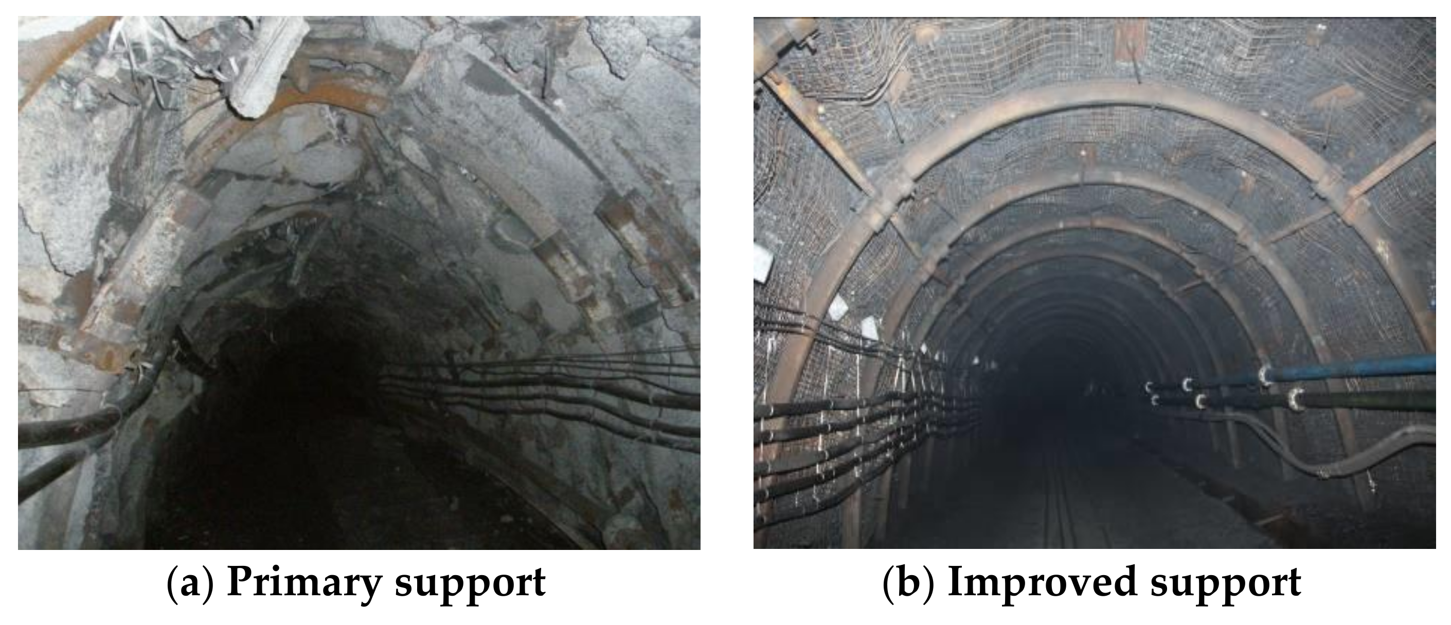
  • Supporting material failure. Many failures occurred soon after supporting materials were installed and failures still occurred even after several repairs. The failure characters of U-shaped steel sets in different areas of the roadway were significantly different. In the serious roof subsidence places, the U-shaped steel sets broke in the arch shoulder, the top section of the U-shaped steel sets was flattened (Figure 4a), and the leg of the U-shaped steel sets was pressed into the rock of the floor. In the serious side shrinkage places, the top of the U-shaped steel sets became sharpened, and the leg of the U-shaped steel became bent (Figure 4c). A series of U-shaped steel sets became distorted along the direction of the roadway axis (Figure 4d), resulting in the U-shaped steel sets almost losing bearing capacity. The failure of U-shaped steel sets indicates that the strength and stiffness of steel bracket was too low to inhibit the large deformation of the soft surrounding rock. The remaining excavation of the roadway was delayed due to serious deformation and potential instability. An improved support system had to be proposed and performed.

3. Large Deformation Mechanism Analysis Using UDEC

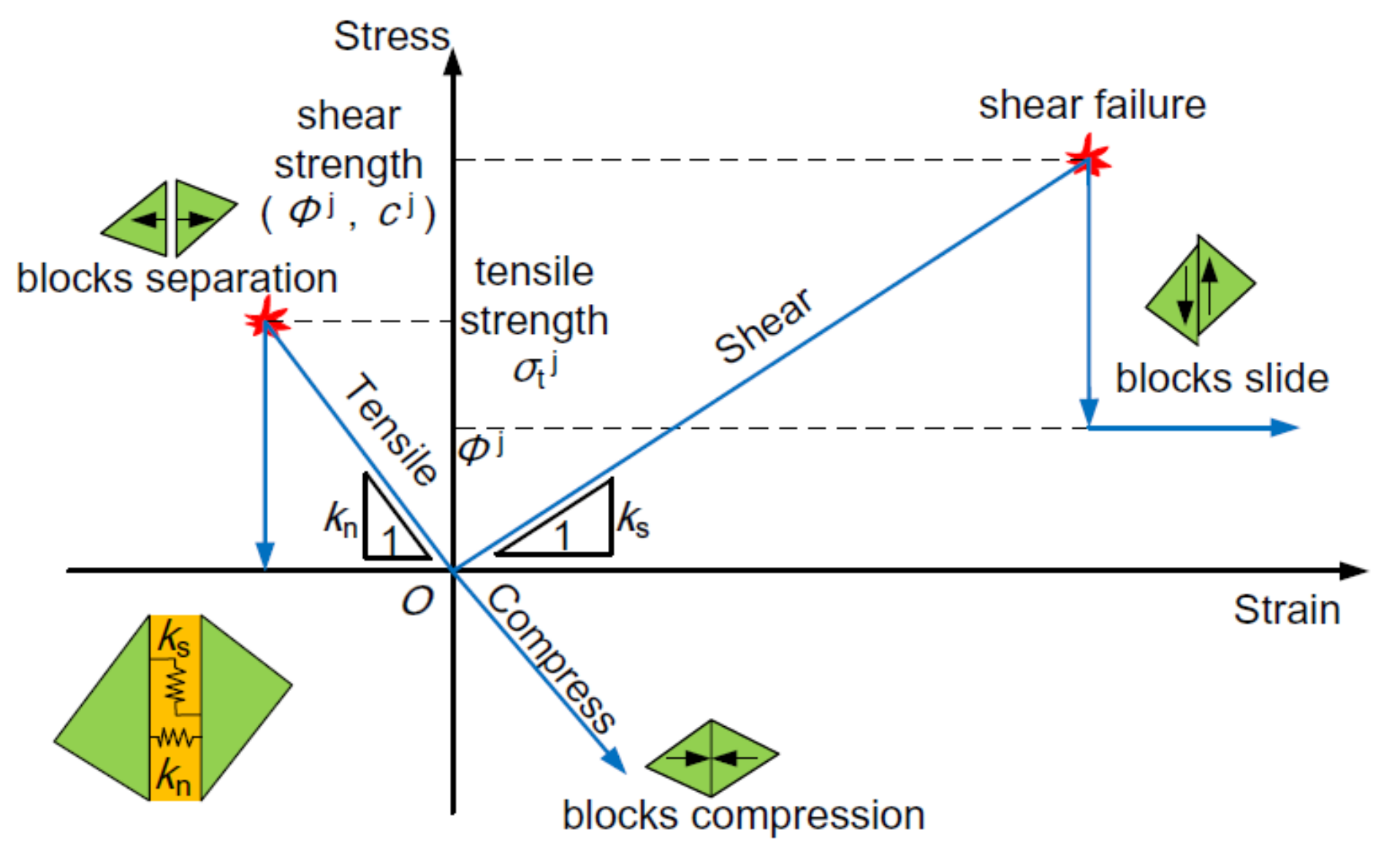
3.1. UDEC Trigon Approach

The UDEC Trigon approach was adopted in this study due to its inherent advantage in simulating the initiation, propagation, interaction, and coalescence of fractures, and evaluating the capability of support materials in suppressing rock mass deformation and dilation [25]. Based on the Voronoi algorithm in UDEC, Voronoi blocks are generated and cut into several constituent trigon blocks with the custom-developed FISH function [25]. The triangular blocks are represented as deformable, elastic finite-difference elements and cemented by contacts between them. The deformation characteristics of trigon blocks are governed by the bulk moduli (K) and shear moduli (G). The triangular blocks are made elastic, and the fracturing failures could only occur by sliding or opening along the contact between adjacent triangular blocks when the relatively stresses acting on the contact exceed its strength. The constitutive model of UDEC Trigon approach is shown in Figure 5.
The spring-rider was adopted to simulate the behavior of a contact. In the normal direction of a contact, the relation of stress–displacement is linear and governed by the normal stiffness (Kn) and limited by the tensile strength:
Δ σ n = K n Δ u n
where Δσn is the increment of normal stress and Δμn is the increment of normal displacement. If the normal stress acting on the contact exceeds its tensile strength, then tensile failure occurs and σn = 0.
In the shear direction along the contact, the stress-displacement relation is governed by the constant shear stiffness (Ks) and the shear strength (τmax), which can be divided into two stages:
If
| τ s | c + σ n tan φ = τ max
then
Δ τ s = K s Δ μ s e
or else, if
| τ s | τ max
then
Δ τ s = sign ( Δ μ s ) τ max
where Δ μ s e is the elastic component of shear displacement increment, and Δμs is the total incremental shear displacement.

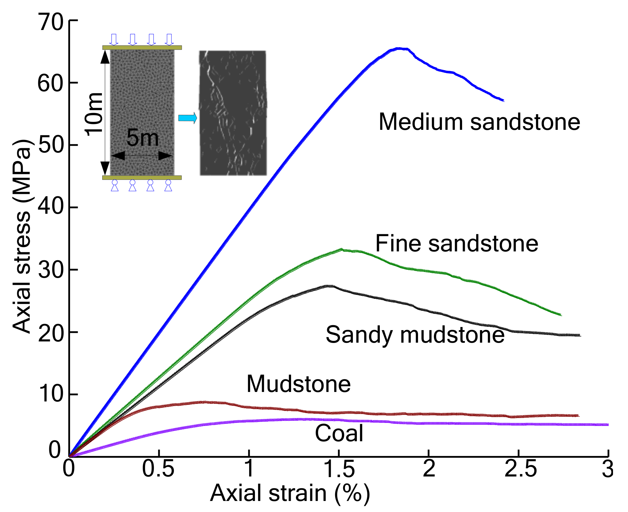
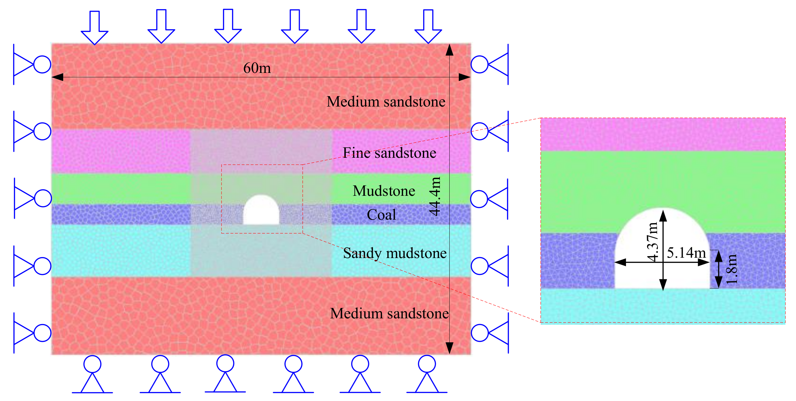
3.2. The Determination of Rock Mass Parameters in UDEC

The bulk modulus (K) and shear modulus (G) of the triangular blocks can be calculated by the following equations [26]:
K = E 3 ( 1 2 μ )
G = E 2 ( 1 + μ )
The normal stiffness (Kn) and shear stiffness (Ks) of contacts can be derived from the following equations:
K n = 10 [ K + 4 3 G Δ Z min ]
K s = 0.4 k n
where ΔZmin is the smallest width in the normal direction of the zone adjoining the contacts [27].
The cohesion (Cj), friction angle(φj) and tensile strength (σtj) of contacts were obtained by undertaking a series of simulated uniaxial compression experiments on synthetic specimens with trigon or Voronoi blocks [25]. The mesh pattern of specimens was consistent with the subsequent roadway excavation model. The original micro-parameters were first estimated according to the material properties and then calibrated iteratively by simulated uniaxial compression tests until the calibrated Young’s modulus and compressive strength were consistent with the properties of rock mass listed in Table 1, as shown in Figure 6. The final mechanical parameters for each layer of stratums are listed in Table 2.

3.3. Discrete Element Model Simulation of Improved Support Scheme

The numerical model of the tailgate model is shown in Figure 7, which is consistent with the lithology of the tailgate illustrated in Figure 2. The dimensions of the model were 60 m in width and 44.4 m in height, which were made up of 13,324 blocks. To enhance the computational efficiency, trigon blocks with edge length of 0.3 m were only generated around the tailgate; the remainder of the numerical model is divided into Voronoi blocks with a graded increasing edge length from 0.6 m to 1.2 m. Constant vertical stress and horizontal stress measured in the field were applied to the upper and lateral boundaries of the model to simulate in situ stress. The bottom and lateral boundaries were constrained. The model was first run to the initial stress equilibrium and then the blocks within the roadway profile were deleted to simulate the excavation.
Roadway models under no-support and primary support conditions were run to reveal the failure characters of soft rock roadway. In the primary support, the U-shaped steel sets and concrete were simulated by the “structure” element built in UDEC. The properties of support elements are shown in Table 3.

3.4. Large Deformation Mechanism in Deep Soft Rock Roadway

Under no-support conditions, heavy cracks developed and a large crack zone formed around the roadway. Shear cracks were mainly generated in the relatively deep surrounding rock while tensile cracks were mainly generated in the shallow surrounding rock (see Figure 8). These tensile cracks caused rock mass to be greatly fragmented and dilation with a large gap between adjacent blocks [28], which led to clear coalesced macroscopic fractures (Figure 9) and significant roadway convergence (Figure 10). Serious roof subsidence, floor heave and side shrinkage failures then appeared, which was consistent with the large deformation failures observed in the field. The generation and propagation of tensile cracks were closely related to localized tensile stresses [29]. A tension crack is formed when the normal stress applied on a contact exceeds its tensile strength. A large tensile stress zone generated around the roadway (Figure 11), which caused the generation of heavy tension cracks. A large stress relaxation zone was generated around the roadway (Figure 12). This was due to the deviator stress caused by excavation exceeding the peak strength of shallow surrounding rock and causing the failing rock to enter the post-failure zone. Then, the stress concentration zone caused by deviator stress propagated further into the deep surrounding rock. It is interesting to find that the tensile stress zone has a similar range with the stress relaxation zone and loosen zone. Under primary support conditions, it is apparent that the installation of the “ U-shaped steel sets + shotcrete” system obviously constrained the generation of the stress concentration zone and tensile stresses (Figure 13); these notably inhibited the post-failure zone (Figure 14) and crack propagation in the roof and ribs where the support system was installed (Figure 15). The depths of the crack zone in the roof and ribs were approximately 2.7 m and 2.3 m, respectively, compared to 3.8 m and 3.3 m with no support. The number of shear cracks was 494, compared to 759 with no support. The depth and extent of the tensile crack zone were also obviously reduced, the number of tension cracks decreased from 461 to 178, leading to a significant decrease in rock mass fragmentation (Figure 16) and roadway contraction (see Figure 17). However, it seems that the initial support did not really stabilize the roadway. For example, the roadway surface with the primary support still exhibited large stress concentration zone and large tensile stresses. The stress concentration and tensile stresses resulted in large post-failure zone and a large amount of tensile failures, and stress relaxation and tensile failures in the floor are still serious. Consequently, fragmentation and large deformation failure still occurred in these areas, which was consistent with the supported areas observed in the field (see Figure 4), so the primary support should have been improved.
Numerical simulation results suggest that the large deformation and poor rock reinforcement was likely caused by the following reasons:
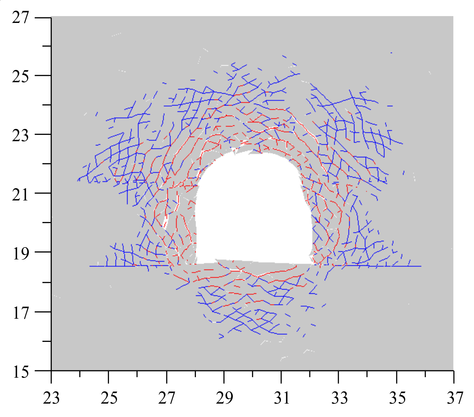
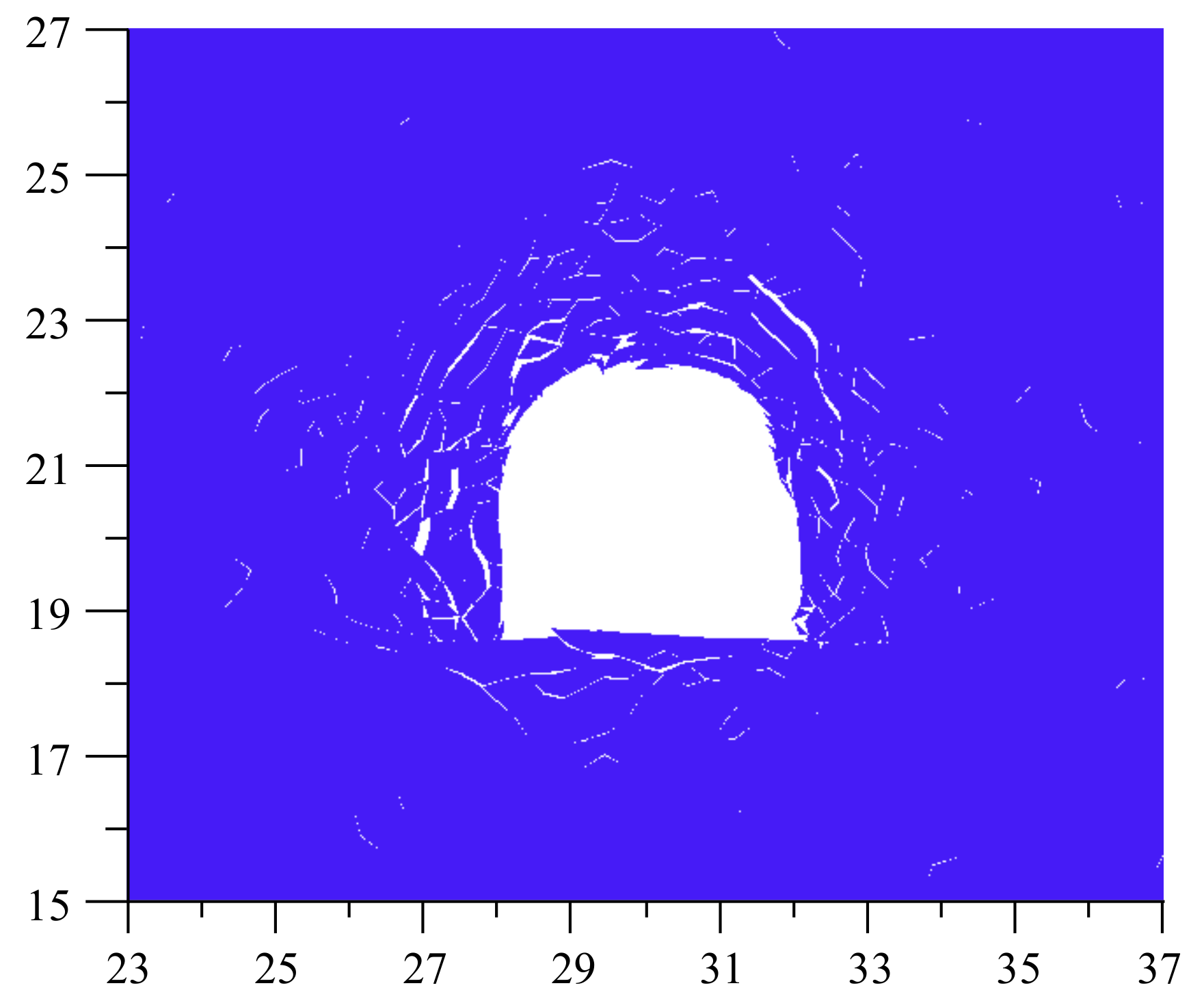
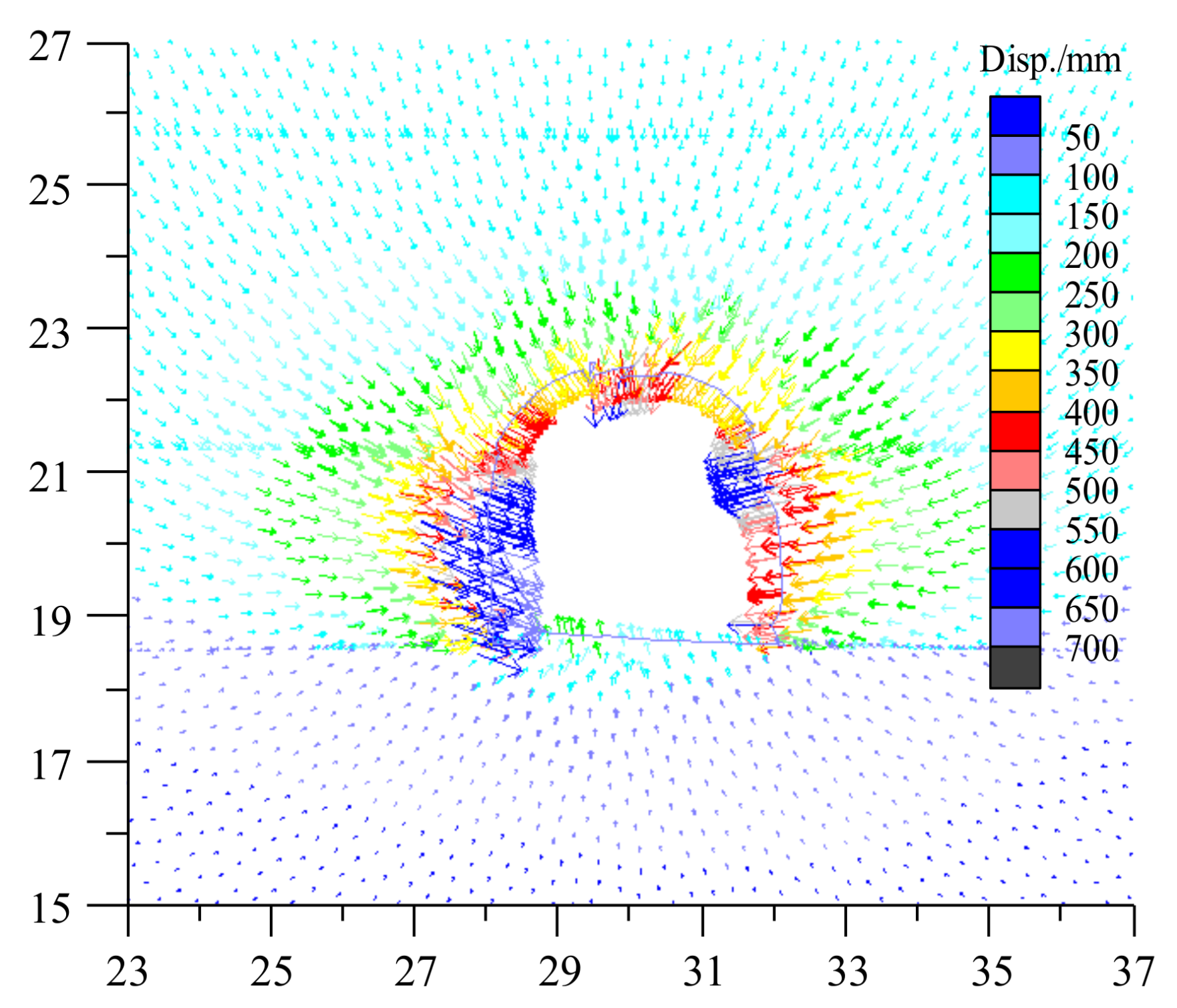
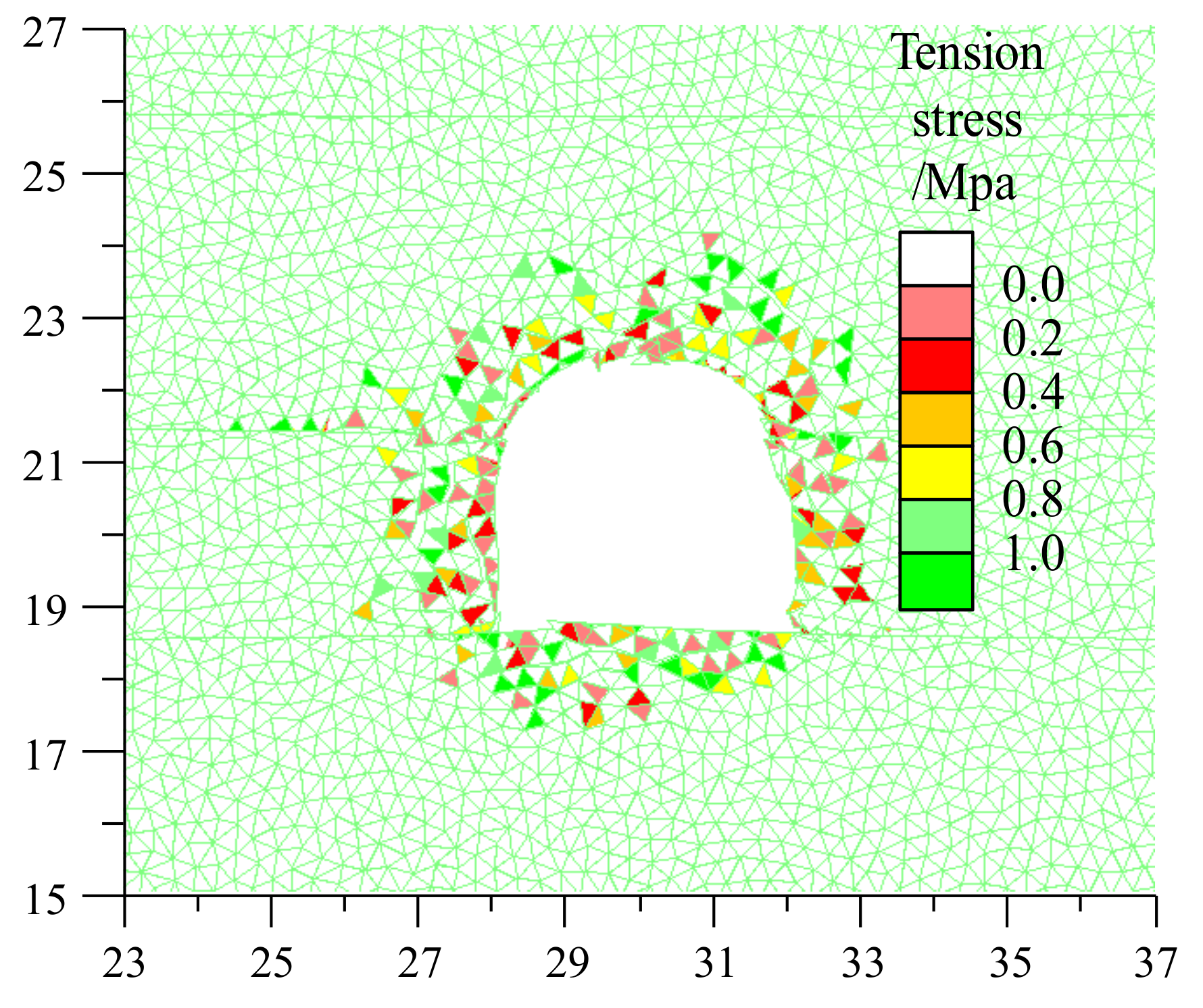
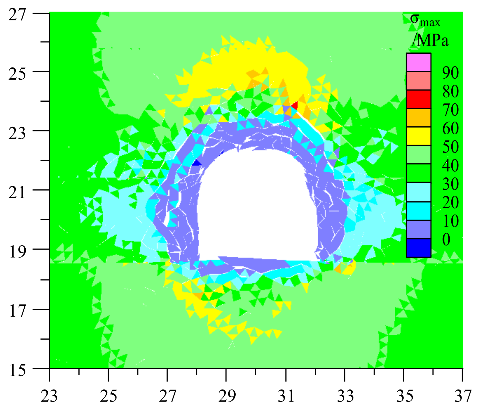
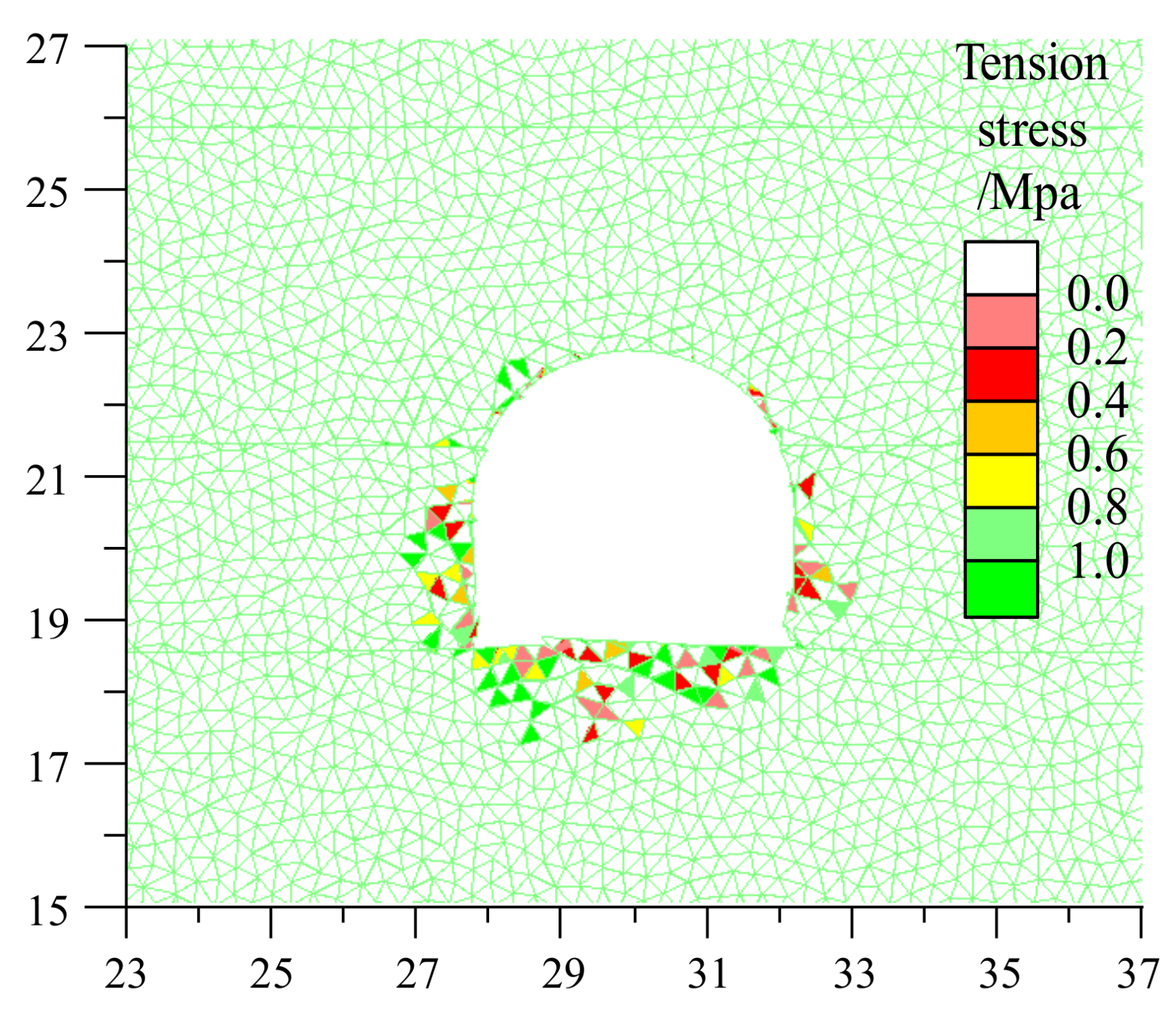
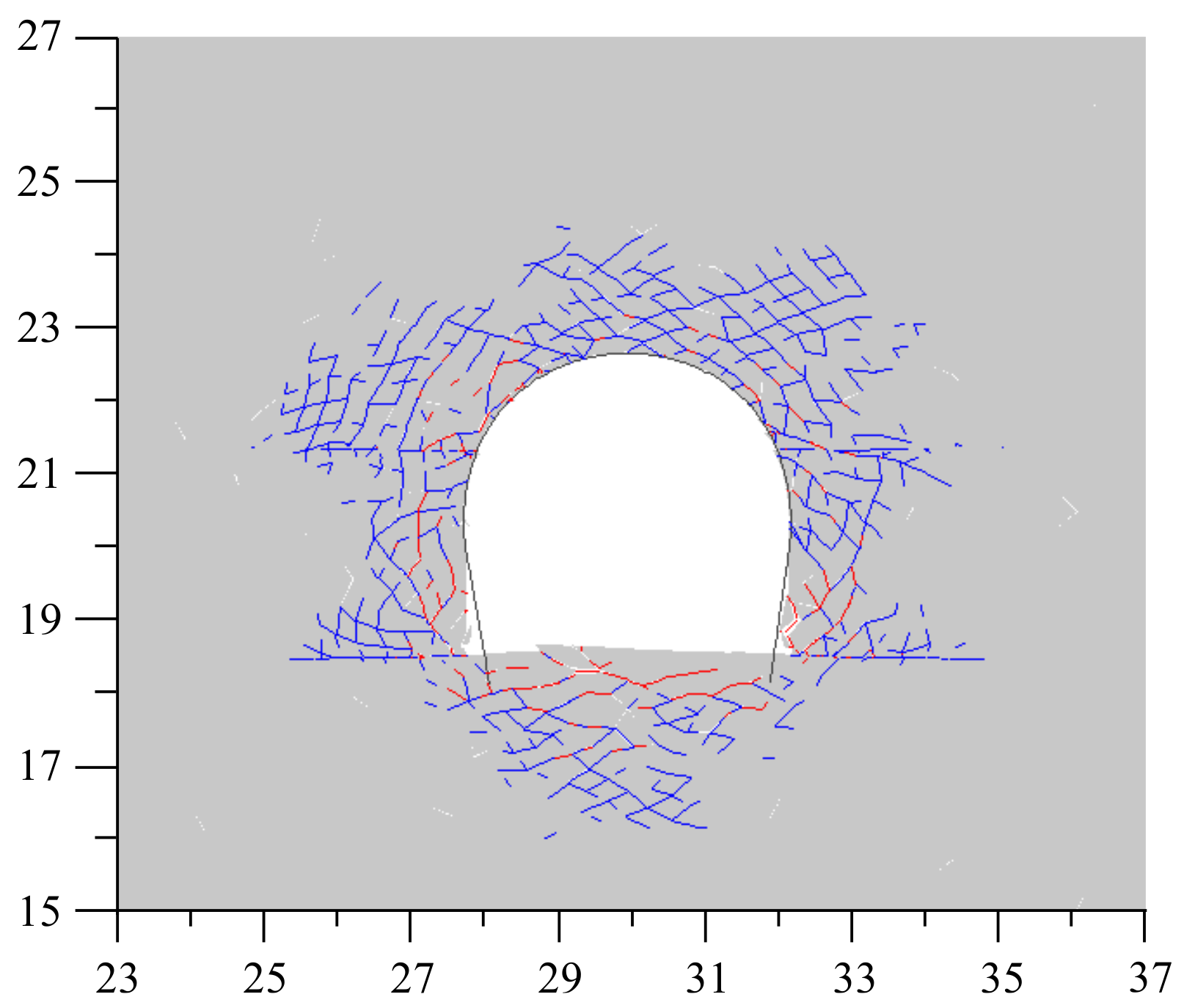
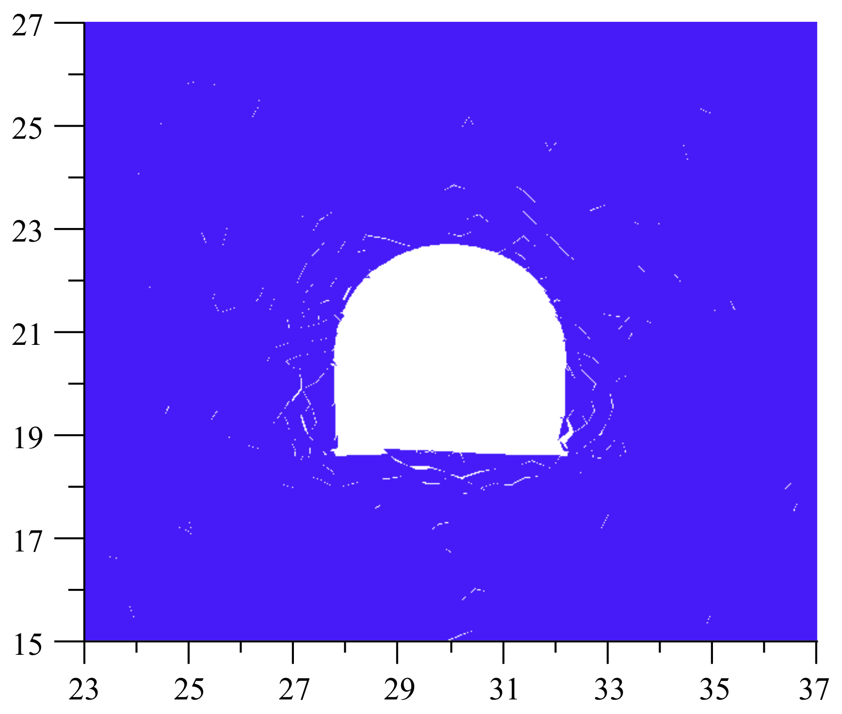
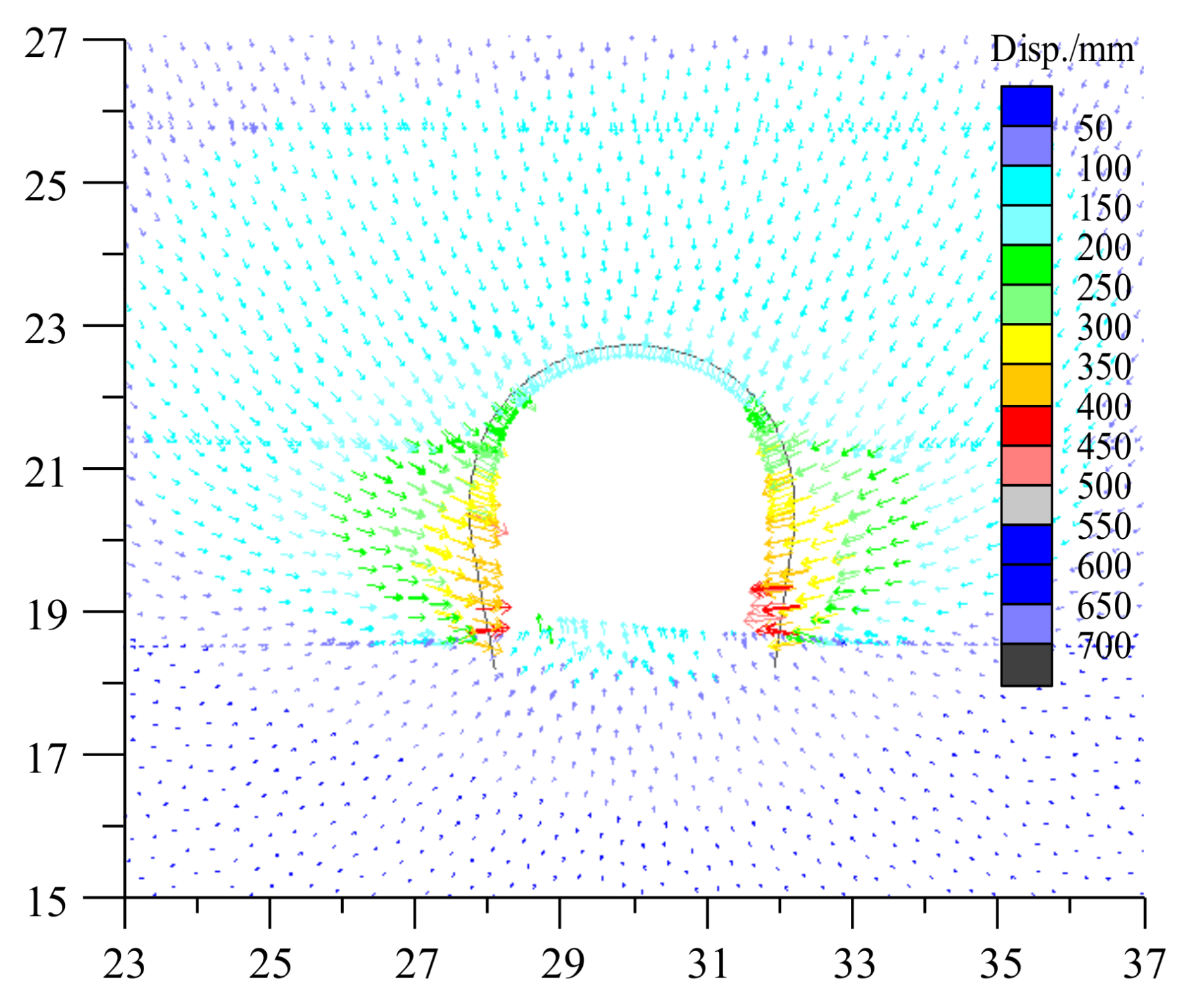
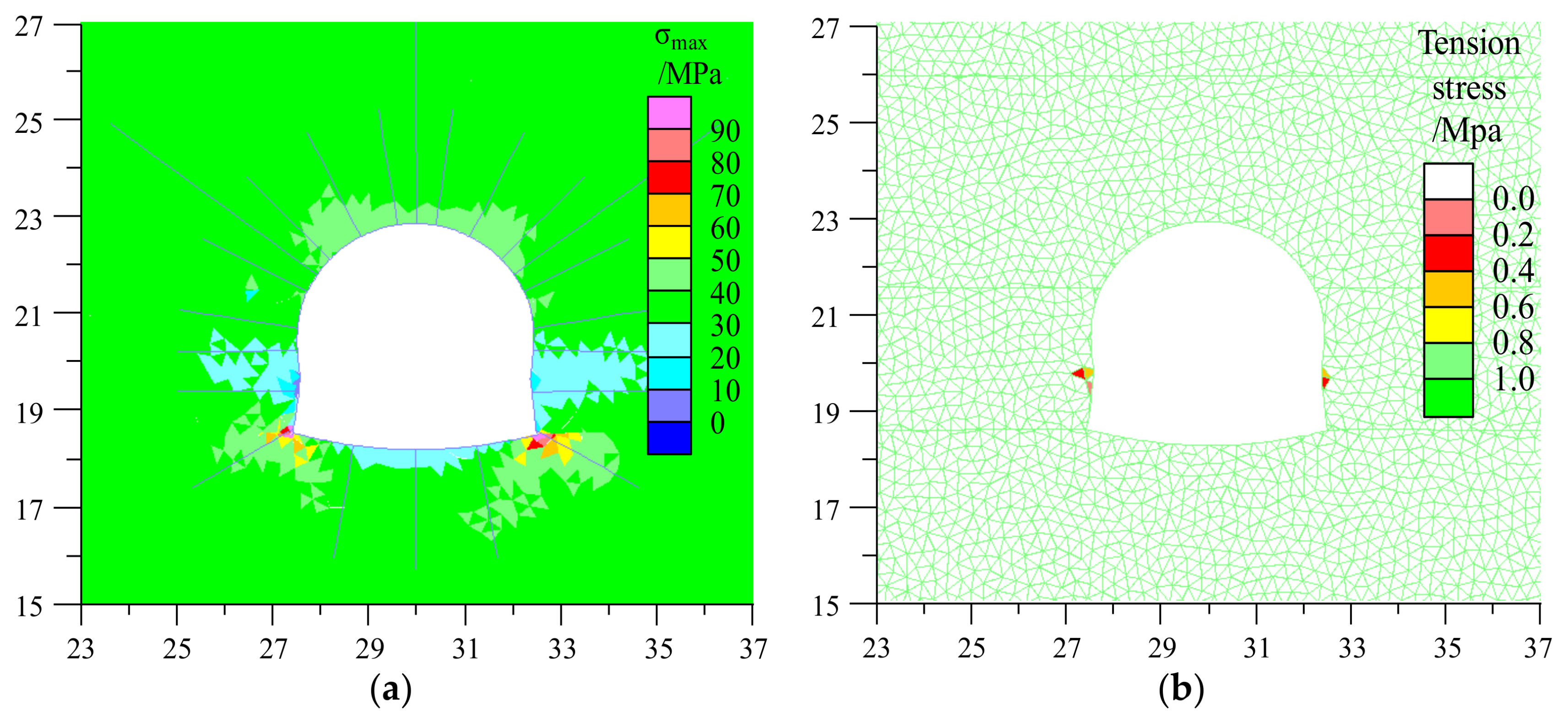
  • The interaction between high deviator stress and low strength soft rock. The ground stress distributed around the tailgate was relatively high due to a buried depth of 800 m. The stress relief in the free face due to excavation resulted in high deviator stress and stress concentration, which exceeded the peak strength of soft surrounding rock and caused shallow weak surrounding rock to enter into the post-failure zone with a low residual strength. Tensile cracks then initiated due to tensile stresses and developed around the roadway, which caused the shallow surrounding rock to lose its bearing capacity and formed a large loose zone.
  • Contradiction between large deformation and incomplete low-strength supporting structure. The compressive capability of the U-shaped steel sets was too weak to resist the large deformation of lose soft rock, and many broken and curved U-shaped steel sets were found in the roadway. In addition, the U-shaped steel sets were installed with insufficient pretension and shrunk seriously. The bearing capacity of shotcrete was poor and the poured shotcrete made it difficult to remove the grid arch frame during mining activities. The “U-shaped steel -shotcrete” support materials were only installed in the ribs and roof of the roadway, which did not constitute an integrated bearing structure on the roadway surface and led to serious floor bending and heaving.

4. Improvement of the Primary Support System

4.1. Support Principles of the Deep Soft Rock Roadway

Previous research has shown that the enhancing of confining pressure can significantly increase the residual strength of surrounding rock and greatly restrain crack propagation [30]. The active flexible support system consisted of whole section bolts, cables, load-bearing plate, ladder beam and wire mesh should be installed in time with sufficient pre-stress to seal, compress and reinforce the shallow rock, which can improve the confining pressure and clamp loose surrounding rocks into integrated stratums [16,17,18].The inverted arch floor was constructed to eliminate the poor force state of the right angle and enhance the bearing capacity of the floor. Full-section rigid U-shaped steel sets were installed to form an enclosed high-strength bearing structure which can resist the large deformation due to excavation.

4.2. Improved Support Scheme

An improved support scheme is proposed as follows: The straight wall and semicircular arch cross section was first excavated with width and height of 5.14 m and 4.37 m. The “bolt-cable-mesh” support structure was installed subsequently. Then, the inverted arch floor was excavated, followed by installation of U-shaped steel sets and floor bolts. Finally, the reinforced concrete was poured in the floor.

4.3. Simulation Verification of Improved Support Scheme

The improved support scheme was simulated to examine its feasibility. The simulated properties of the support elements are illustrated in Table 3 and Table 4.
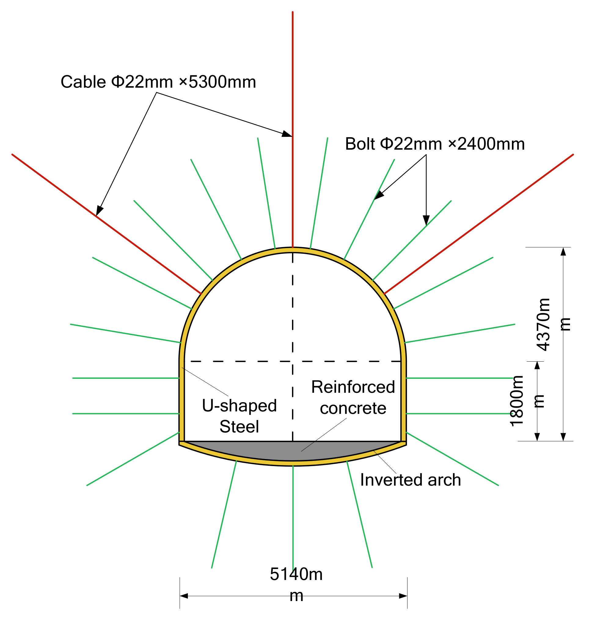
  • “Bolt-cable-mesh” flexible support structure. Seventeen Φ22 mm × 2400 mm bolts were installed in the full cross-section with row spacing of 800 mm and column spacing of 900 mm. The tensile resistance of those bolts was not less than 120 kN with a pretension of 80 kN. Three Φ18.9 mm × 5300 mm cables were installed with high strength steel plates that were 450 mm long × 280 mm wide × 4 mm thick in the roof. The row spacing and column spacing of cables were 1600 mm × 2700 mm. The tensile capability of these cables was no less than 300 kN with a pretension of 120 kN. Bolts were designed to be installed with ladder beam 4000 mm long and wire mesh with a grid size of 100 mm × 100 mm.
  • “Full-section U-shaped steel sets” rigid support structure. During construction of the yieldable 36 U-shaped steel sets, the inverted arch floor was first constructed. The rise–span ratio and rise of inverted arch floor were 1:12 and 400 mm, respectively. The 36 U-shaped steel sets were connected and fastened by five clamps with a pre-tightening torque of 300 N·m. After setting up the U-shaped steel sets, the shotcrete was poured in the inverted arch floor with a thickness of 350–400 mm. The strength of shotcrete was C20. The final support plan is shown in Figure 18.
The improved support scheme was successful at suppressing the development of cracks, as can be seen in Figure 19a. Only slight shear cracks developed in the sides and floor and tensile cracking barely propagated. Consequently, there was no noticeable dilation or fractures in the surrounding rock (Figure 19b). Meanwhile, the improved support scheme effectively improved the stress state around the roadway, the stress concentration zone (Figure 20a) and the tensile stresses (Figure 20b) were significantly reduced, especially in the floor.
The displacement vector of the tailgate with an improved support structure (Figure 21) indicated that deformation degree and range was significantly reduced, and the deformation distribution tended to be uniform with no evident dilation. The displacement data at different depths of roof, sides and floor under different support conditions were extracted and made into curves (Figure 22). The violent variation of the displacement caused by the fragmented and dilation of surrounding rock disappeared. The convergences in the roof, sides and floor under improved support were 50 mm, 219 mm and 68 mm, respectively. Compared to the 173 mm, 699 mm, and 170 mm with the primary support, the reduction rates were 71%, 69%, and 60%, respectively, and the floor heave has been decreased significantly.

4.4. Field application of Improved Support Scheme

The improved support structure was constructed in the remaining excavation of the 31041 tailgate. The surface convergences of the tailgate starting with the excavation were monitored to measure the effectiveness of the improved support structure. Monitoring stations were arranged in two locations as shown in Figure 1b. The convergences curves of Station #2 and Station #3 are shown in Figure 23. The excavation of the roadway caused increasing swelling strain energy. On the one hand, the improved support system resists it by improving the stress state and residual strength of soft surrounding rock; on the other hand, it releases the swelling strain energy by allowing a controllable yielding and deformation in surrounding rock. The continuous interaction between stress and deformation in the surrounding rock lasted for about 35 days, the deformation in the surrounding rock kept increasing in a controllable range. After the roadway profile was excavated for 35 days, the convergence increased slowly and became stable, which indicates that the adjustment of deviator stress in surrounding rock reached the equilibrium state. The final roof subsidence, wall-to-wall and floor heave convergences were 40–50 mm, 140–160 mm and 50–60 mm, respectively. The deformation was controlled in allowable range and generally maintained the outline of the tailgate. The wall-to-wall and roof-to-floor contraction ratio was only 3% and 2.5%, respectively, which indicated that the improved support structure had successfully controlled the large deformation in soft surrounding rock, as seen in Figure 24.

5. Conclusions

Supporting deep soft roadway has been a recurring challenge in mining engineering. This paper presents a study on large deformation mechanism and stability control techniques of a typical roadway excavated in deep soft rock masses. The tailgate serving the 31041 longwall panel in Chao’hua coal mine exhibits serious, large deformation failure during excavation. A field test of rock mass strength reveals that the quality of surrounding rock was extremely poor and weak. The UDEC Trigon approach is adopted to establish a detailed numerical model for the tailgate. The failure patterns of tailgate under unsupported and primary support conditions are successfully reproduced, and the distribution rules of the crack propagation, deformation, and stress state in surrounding rock are concluded.
Based on the field investigation and numerical simulation results, the large deformation mechanism of the tailgate is revealed: The high ground stress is released in the free face due to excavation and this results in the high deviator stress that causes shallow weak surrounding rock to lose its bearing capacity and form a large loose stress relaxation zone. Large deformation characters such as fragmentation, dilation and separation then appear in shallow surrounding rock. The compressive capability of primary support is too weak to resist the large deformation of the loose soft rock. Serious convergence in the sides, roof and floor eventually occur in the surrounding rock of the roadway.
A cross-section optimization and full-section “bolt-cable-mesh” is presented to improve the stress state and residual strength in shallow surrounding rock. Full-section rigid U-shaped steel sets are installed to form an enclosed support structure with high support strength. The control effect of the improved support system is examined by numerical method and field test, which demonstrate that the roadway stability is effectively improved and significant contraction in the roadway profile is successfully inhibited over a long period.
Deep mining is an eternal task that must be solved as long as human activities develop toward deeper parts of the earth. This paper could provide some references for studies on failure mechanism and stability control techniques of roadways excavated in deep soft rock stratums, which occur large and long-term duration deformation characters. Further study of other rock mechanics problems of deep mining engineering, such as the increase of sudden engineering disasters and deterioration of operating environment caused by high ground stress, high ground temperature, high gas, high hydraulic pressure, etc., can provide a strong theoretical foundation and technical support for the safe, economical, rational, and sustainable develop of deep resources worldwide.

Acknowledgments

This research was supported by the National Natural Science Foundation of China (41672347), which is gratefully acknowledged.

Author Contributions

Xiaojie Yang and Eryu Wang conceived and designed the research; Eryu Wang performed the numerical simulation and field tests; . Eryu Wang and Yajun Wang performed the laboratory experiments; Yubing Gao and Pu Wang provided theoretical guidance in the research process; Eryu Wang analyzed the data and wrote the paper.

Conflicts of Interest

The authors declare no conflict of interest.

References

  1. Xie, H.P.; Gao, F.; Ju, Y. Research and development of rock mechanics in deep ground engineering. Chin. J. Rock Mech. Eng. 2015, 34, 2161–2178. [Google Scholar] [CrossRef]
  2. Xie, H.P. Research Framework and Anticipated Results of Deep Rock Mechanics and Mining Theory. Adv. Eng. Sci. 2017, 49, 1–16. [Google Scholar] [CrossRef]
  3. He, M.C. Progress and challenges of soft rock engineering in depth. J. China Coal Soc. 2014, 39, 1409–1417. [Google Scholar] [CrossRef]
  4. Milici, R.C.; Flores, R.M.; Stricker, G.D. Coal resources, reserves and peak coal production in the United States. Int. J. Coal Geol. 2013, 113, 109–115. [Google Scholar] [CrossRef]
  5. Lechner, A.M.; Kassulke, O.; Unger, C. Spatial assessment of open cut coal mining progressive rehabilitation to support the monitoring of rehabilitation liabilities. Resour. Policy 2016, 50, 234–243. [Google Scholar] [CrossRef]
  6. He, M.C.; Xie, H.P.; Peng, S.P.; Jiang, Y.D. Study on rock mechanics in deep mining engineering. Chin. J. Rock Mech. Eng. 2005, 24, 2803–2813. [Google Scholar] [CrossRef]
  7. Gao, Y.B.; Liu, D.Q.; Zhang, X.Y.; He, M.C. Analysis and optimization of entry stability in underground longwall mining. Sustainability 2017, 9, 2079. [Google Scholar] [CrossRef]
  8. Yang, S.Q.; Chen, M.; Jing, H.W.; Chen, K.F.; Meng, B. A case study on large deformation failure mechanism of deep soft rock roadway in Xin’An coal mine, China. Eng. Geol. 2016, 217, 89–101. [Google Scholar] [CrossRef]
  9. Yang, X.J.; Pang, J.W.; Liu, D.M.; Liu, Y.; Tian, Y.H.; Ma, J.; Li, S.H. Deformation mechanism of roadways in deep soft rock at Hegang Xing’an Coal Mine. Int. J. Min. Sci. Technol. 2013, 23, 307–312. [Google Scholar] [CrossRef]
  10. Kang, H.P.; Lin, J.; Fan, M.J. Investigation on support pattern of a coal mine roadway within soft rocks—A case study. Int. J. Coal Geol. 2015, 140, 31–40. [Google Scholar] [CrossRef]
  11. Wang, P.; Jiang, L.S.; Jiang, J.Q.; Zheng, P.Q.; Li, W. Strata behaviors and rock burst–inducing mechanism under the coupling effect of a hard, thick stratum and a normal fault. Int. J. Geomech. 2018, 18, 04017135. [Google Scholar] [CrossRef]
  12. Jiao, Y.Y.; Song, L.; Wang, X.Z.; Coffi Adoko, A. Improvement of the U-shaped steel sets for supporting the roadways in loose thick coal seam. Int. J. Rock Mech. Min. Sci. 2013, 60, 19–25. [Google Scholar] [CrossRef]
  13. Zhao, Y.M.; Liu, N.; Zheng, X.G.; Zhang, N. Mechanical model for controlling floor heave in deep roadways with U-shaped steel closed support. Int. J. Min. Sci. Technol. 2015, 25, 713–720. [Google Scholar] [CrossRef]
  14. Wang, C.; Wang, Y.; Lu, S. Deformational behaviour of roadways in soft rocks in underground coal mines and principles for stability control. Int. J. Rock Mech. Min. Sci. 2000, 37, 937–946. [Google Scholar] [CrossRef]
  15. Kang, H.P. Support technologies for deep and complex roadways in underground coal mines: A review. Int. J. Coal Sci. Technol. 2014, 1, 261–277. [Google Scholar] [CrossRef]
  16. Ghazvinian, A.; Sarfarazi, V.; Schubert, W.; Blumel, M. A study of the failure mechanism of planar non-persistent open joints using PFC2D. Rock Mech. Rock. Eng. 2012, 45, 677–693. [Google Scholar] [CrossRef]
  17. Goel, R.K.; Swarup, A.; Sheorey, P.R. Bolt length requirement in underground openings. Int. J. Rock Mech. Min. Sci. 2007, 44, 802–811. [Google Scholar] [CrossRef]
  18. Karanam, U.M.R.; Dasyapu, S.K. Experimental and numerical investigations of stresses in a fully grouted rock bolts. Geotech. Geol. Eng. 2005, 23, 297–308. [Google Scholar] [CrossRef]
  19. Peng, S. Roof bolting adds stability to weak strata. Coal Age Mag. 1998, 11, 32–38. [Google Scholar]
  20. Mark, C. Design of roof bolt system. In Proceeding of New Technology for Coal Mine Roof Support; NIOSH: Washington, DC, USA, 2000; pp. 111–131. [Google Scholar]
  21. Yang, X.J.; Pang, J.W.; Lou, H.P.; Fan, L.P. Characteristics of in situ stress field at Qingshui coal mine. Int. J. Min. Sci. Technol. 2015, 25, 497–501. [Google Scholar] [CrossRef]
  22. Fairhurst, C.E.; Hudson, J.A. Draft ISRM suggested method for the complete stress-strain curve for the intact rock in uniaxial compression. Int. J. Rock Mech. Min. 1999, 36, 279–289. [Google Scholar] [CrossRef]
  23. Zhang, L.; Einstein, H.H. Using RQD to estimate the deformation modulus of rock masses. Int. J. Rock. Mech. Min. Sci. 2004, 41, 337–341. [Google Scholar] [CrossRef]
  24. Singh, M.; Seshagiri, R.K. Empirical methods to estimate the strength of jointed rock masses. Eng. Geol. 2005, 77, 127–137. [Google Scholar] [CrossRef]
  25. Gao, F.Q.; Stead, D. The application of a modified Voronoi logic to brittle fracture modelling at the laboratory and field scale. Int. J. Rock Mech. Min. Sci. 2014, 68, 1–14. [Google Scholar] [CrossRef]
  26. Brady, B.H.G.; Brown, E.T. Rock Mechanics for Underground Mining, 3rd ed.; Springer Science and Business Media: New York, NY, USA, 2006. [Google Scholar]
  27. Itasca Consulting Group, Inc. UDEC User Manual; Itasca Consulting Group, Inc.: Minneapolis, MN, USA, 2008. [Google Scholar]
  28. Yu, W.J.; Wang, W.J.; Chen, X.Y.; Du, S.H. Field investigations of high stress soft surrounding rocks and deformation control. J. Rock Mech. Geotech. Eng. 2015, 7, 421–433. [Google Scholar] [CrossRef]
  29. Diederichs, M.; Kaiser, P.; Eberhardt, E. Damage initiation and propagation in hard rock during tunnelling and the influence of near-face stress rotation. Int. J. Rock Mech. Min. Sci. 2004, 41, 785–812. [Google Scholar] [CrossRef]
  30. Gao, F.Q.; Kang, H.P. Effects of pre-existing discontinuities on the residual strength of rock mass–Insight from a discrete element method simulation. J. Struct. Geol. 2016, 85, 40–50. [Google Scholar] [CrossRef]
Figure 1. (a) The location of the Chao’hua coal mine, Henan, China. (b) Plan of the investigated longwall panel and roadways in the Chao’hua coal mine.
Sustainability 10 01100 g001
Figure 2. Stratum column and geological description at the study site.
Sustainability 10 01100 g002
Figure 3. Borehole optical televiewer images of surrounding rock at various depths (a-i) in the study site.
Sustainability 10 01100 g003aSustainability 10 01100 g003b
Figure 4. Failure mode in the tailgate of Chao’hua coal mine. (a) Roof subsidence and sides shrinking; (b) Floor heave; (c) Support bending; (d) Support failure.
Sustainability 10 01100 g004
Figure 5. Constitutive model of UDEC Trigon approach [8].
Sustainability 10 01100 g005
Figure 6. Simulated uniaxial compression stress–strain curves for the rock mass.
Sustainability 10 01100 g006
Figure 7. Geometry and boundary condition of tailgate numerical model.
Sustainability 10 01100 g007
Figure 8. Simulated crack modes of the roadway under no support type. Tensile and shear cracks are marked by red and blue, respectively. S/T indicates the number of shear cracks number and tensile cracks. S/T = 759/461.
Sustainability 10 01100 g008
Figure 9. Simulated failure patterns around the roadway under no support type.
Sustainability 10 01100 g009
Figure 10. Simulated displacement vectors around the roadway under no support type.
Sustainability 10 01100 g010
Figure 11. Simulated tensile stresses around the roadway under no support types.
Sustainability 10 01100 g011
Figure 12. Simulated maximum principal stresses around the roadway under no support types.
Sustainability 10 01100 g012
Figure 13. Simulated tensile stresses around the roadway under primary support types.
Sustainability 10 01100 g013
Figure 14. Simulated maximum principal stresses around the roadway under primary support types.
Sustainability 10 01100 g014
Figure 15. Simulated crack modes of the roadway under primary support type. Tensile and shear cracks are marked by red and blue, respectively. S/T indicates the number of shear cracks number and tensile cracks. S/T = 494/178.
Sustainability 10 01100 g015
Figure 16. Simulated failure patterns around the roadway under primary support type.
Sustainability 10 01100 g016
Figure 17. Simulated displacement vectors around the roadway under primary support type.
Sustainability 10 01100 g017
Figure 18. The arrangement plan of the “bolt-cable-mesh + shell” support scheme.
Sustainability 10 01100 g018
Figure 19. Simulated crack modes (a) and failure patterns (b) around tailgate under improved support scheme.
Sustainability 10 01100 g019
Figure 20. Simulated principal stresses around the roadway under different support types. (a) Maximum principal stresses; (b) Tensile stresses.
Sustainability 10 01100 g020
Figure 21. UDEC model predicted displacement vector around the tailgate under improved support scheme.
Sustainability 10 01100 g021
Figure 22. Displacement of monitoring lines in surrounding rock under the improved support scheme.
Sustainability 10 01100 g022
Figure 23. Monitored convergence of the 31041 tailgate during excavation. (a) Monitoring Station #2; (b) Monitoring Station #3.
Sustainability 10 01100 g023
Figure 24. Photographs taken in the 31041 tailgate under different support types showing a successful reinforcement. (a) Primary support; (b) Improved support.
Sustainability 10 01100 g024
Table 1. Intact rock properties and calculated rock mass properties in Chaohua coal mine.
LithologyIntact RockRock Mass
σci (MPa)Eci (GPa)RQDEm (GPa)σcm (MPa)σtm (MPa)
Medium sandstone103.06.36873.2565.666.57
Fine sandstone59.65.82812.331.993.2
Mudstone21.44.66711.28.620.86
Coal19.22.46620.435.970.6
Sandy mudstone54.55.47781.926.842.68
Table 2. Calibrated rock mass mechanical parameters.
LithologyMatrix PropertiesContact Properties
Density (kg·m−3)E GPaKn (GPa·m−1)Ks (GPa·m−1)Cj (MPa)φj (°)σtj (MPa)
Medium sandstone27503.25314.3125.79.93426.57
Fine sandstone26802.3237.5956.8323.2
Mudstone21401.2172.469.11.95210.86
2#Coal19200.4394.9381.45190.6
Sandy mudstone26001.9214.9866.29272.68
Table 3. Parameters of the primary support elements in UDEC.
ParametersElastic Moduli (GPa)Tensile Strength (MPa)Compressive Strength (MPa)Contact Normal Stiffness (GPa·m-1)Contact Shear Stiffness (GPa·m-1)
U-shaped steel sets200505044
Concrete30.52.216.722
Table 4. Parameters of the bolt and cable elements used in UDEC.
ParametersDensity (kg·m−3)Elastic Moduli (GPa)Tensile Capability (kN)Bond Stiffness (N/m2)Bond Strength (N/m)Pretension (kN)
Cable75002003002e94e5120
Bolt75002001202e94e580

