1. Introduction
The gravel formation in western Taiwan is composed of gravel particles and fine-grained materials. The engineering properties of the materials are affected by the following factors: differences in the material structure (such as the particle size distribution of the gravel layer and the degree of cementation) and other external natural factors (such as running water). The gravel layer is formed by the original accumulation of gravel from faults, river erosion or cutting, and other factors to form the current hilly and platform terrain. The gravel in the gravel layer is formed by the weathering of rock, which is transported, deposited, and consolidated by high-energy water flow, so its characteristics are mainly affected by the properties of the parent rock. The gravel parent rock is divided into three types according to its lithology: quartz, sandstone, and schist [
1]. The structural behavior of foundation excavations and retaining work belongs to the mutual control behavior of the structure and soil because the factors affecting excavation are quite complex. When analyzing the structural behavior of retaining walls, factors such as soil properties, layer changes, wall displacement behavior, Earth pressure changes, groundwater pressure changes, support types, and pre-pressure must be considered [
2]. The difference between the underground excavation methods for the gravel layer and the general soil layer is that the focus of attention is different due to the variance in geological conditions. Generally, underground excavations of the soil layer are relatively weak, and the lateral Earth pressure is large, so the penetration depth of retaining walls is great, and there are problems such as sand surge, uplift of the excavation surface, and subsidence caused by pumping. However, the gravel layer is not easy to excavate due to its compactness and hardness, especially when it contains large-sized gravel, but the seriousness of the above problems does not exist. How can the construction method for retaining soil be chosen? The main factors affecting the choice of underground excavation construction methods for stone layers are the base conditions, feasibility, the economy of the construction methods, the construction period, environmental protection, safety and quality requirements, etc. [
3,
4,
5].
Pile-based soft soil improvement has been increasingly used as a rapid construction technique for railway and highway subgrades in soft soil areas. While most studies performed to date have only addressed the stability and settlement of pile-supported embankments under static loads, very limited attention has been paid to understanding their mechanical behavior in gravel layers. In order to cause the method of construction of retaining piles to be widely used in the underground excavation of gravel layers, this study takes the project of a railway station in a metropolitan area as a research case. Due to the deep excavation next to a railway track, the environmental conditions of construction were quite difficult. For example, there was high-voltage electricity along the railway line and potential problems such as being too close to the track. Therefore, the original design in which the construction method of full-casing foundation piles with a diameter of 100 cm was adopted was abandoned, and a mechanical construction method using retaining piles was adopted, and it was applied to deep excavation and retaining work beside an existing and running railway [
6]. The gravel layer in western Taiwan is composed of gravel particles and fine-grained materials. The content of gravel in the Taichung area is as high as 79%, and its parent rock is quartz sandstone, with a high strength and hardness [
7]. The excavation and construction of the gravel layer need to include an evaluation of the mechanical properties that are necessary for a quality design that ensures the stability of the excavated area [
8,
9,
10,
11].
In metropolitan areas, the construction of underground excavations can adversely affect adjacent existing piles. Therefore, it is important to discuss the side deformation and bending moment of piles caused by excavation by using numerical analysis to ensure the stability of the structures [
12,
13,
14,
15]. In addition, the behavior of groups of piles during excavations that induce surface displacement was analyzed by using the finite element method, which was able to simulate the construction sequence, including the excavation of the soil mass, the deformation caused by the excavation process, and the installation of pillars [
6,
7,
8]. Numerous new insights on the response of a single pile to adjacent excavations in the foundation were published, and three-dimensional numerical parametric studies were carried out to simulate the mechanical behavior of a single pile. It was found that the response of a single pile to an excavation depended on the ground level of the excavation and the embedded depth of the wall [
16,
17,
18,
19,
20,
21]. In addition, according to the response of a group of piles near the deep foundation pit, several studies using 3D finite element analysis of the effect of a group of piles were carried out, and the mechanical behavior during excavation and the support of the adjacent deep foundation pit was discussed [
22,
23,
24,
25,
26]. Many studies have focused on the problem of train-induced vibration and the mechanical behavior of moving vehicles under transient loads [
27,
28,
29,
30].
In this study, through the study of mechanical parameters, analysis of monitoring data (inclinometer and railway track subsidence points), and calculation of a 3D finite element program developed in the laboratory, a simulation and analysis of an underground excavation of the gravel layer adjacent to the railway track of a station were carried out. The mechanical behavior of retaining piles is also discussed to provide a reference for the constructability, applicability, and safety of a construction method for retaining piles in underground excavation and retaining engineering.
2. Description of the Engineering Background
2.1. Project Overview
The station structure studied in this paper is a new railway station in the city of Taichung in Taiwan, and it can be divided into two parts: the main structure of the station and the transfer station on the north side. The main structure of the station is a structure with one underground floor and two floors above ground, and the basement area’s foundation is a raft foundation. The excavation depth of the gravel layer is G.L.-6.75 M, as shown in
Figure 1.
To meet the needs of operational safety for the existing railway, this project should be constructed in two stages, and earth-retaining facilities should be set up between the first and second stages. The structure of the first stage is called a vertical wall (section: 400 cm × 30 cm). Under the principle of causing less disturbance to the railway track due to small excavations, the purpose of setting up the vertical wall is to provide pre-support and stabilization functions for the second-stage retaining piles, which are excavated with a large number of layers of gravel. After the first stage of the structure is completed, track switching can be implemented, and the second stage of excavation can be continued. The retaining system of this part was originally designed as a full-casing foundation pile with a diameter of 100 cm and a two-layer back-pull-type ground anchor. To consider various potential hazards during the construction of the full-casing foundation piles (such as the construction problem of the turning radius of the adjacent track and high-voltage electricity along railway lines) and to take the construction safety, environmental maintenance, and passenger safety on the train into account, this study proposes an alternative construction method according to the general terms and construction drawings. The retaining piles are 120 cm long and 60 cm wide, with a spacing of 2.0 m and a back-pull ground anchor, and the intended depth of application is 9.25 m below the surface.
Figure 2 shows a diagram of the construction sequence of the excavation of the gravel layer, the vertical wall, and the retaining pile. The relevant construction photos of this project are shown in
Figure 3.
2.2. Water Removal Operation on the Gravel Layer
Regarding the work on the water-pumping well, the project base was located in the Taichung Basin, where the stratum is a gravel layer with a high permeability and high flow. According to geological survey data, the groundwater level of the gravel layer at the base is about 3.5 m below the surface. Dewatering operations were carried out through pumping wells buried in the gravel layer to keep the excavation surface dry and to maintain the stability of the open cut in the gravel and slope between retaining piles. When the structure was in the backfill stage, to avoid a rise in the water level, the water pressure on the surface of the raft base increased. When the load of the building did not yet provide resistance to buoyancy, it was still necessary to strictly control the groundwater pressure on the base of the raft with pumping facilities. The initial groundwater level of the gravel in this project was conservatively taken 3.0 m below the surface for precipitation analysis. During the construction of the retaining piles in this project, the gravel water level needed to be lowered to 10.25 m below the surface. When the initially designed groundwater was 3.0 m below the surface, the estimated discharge drop demand was 7.25 m to prevent the gravel from collapsing due to seepage, thus creating danger for adjacent railway tracks.
2.3. Monitoring Program for Excavation and Retaining Piles
For the safety monitoring of the excavation of the foundation, in the confirmation of the retaining pile design, it was necessary to compare the data obtained from the monitoring with the parameters used in the design stage to understand whether the engineering design was too conservative or wasteful and to provide the relevant engineering changes or parameters required for remediation processing. During the whole excavation process, the monitoring system was able to reflect information about safety measures at any time; these could be used to judge whether the construction stage was safe or not and had the function of an early warning. When necessary, it could be used as the basis for reinforcement measures, emergency disaster treatment, and truly grasping the safety of construction.
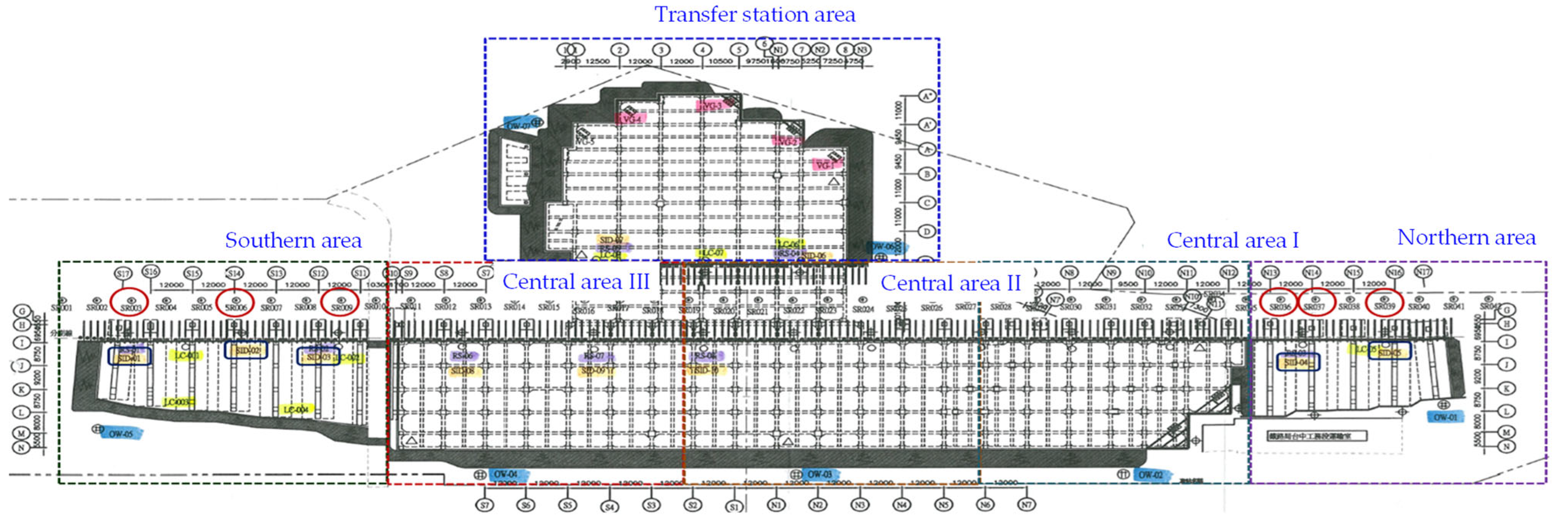
During construction, through the installation of monitoring instruments, changes in the displacement of the gravel layer, water level, stress of the retaining piles, and subsidence of adjacent railway tracks were monitored to ensure the smooth progress of the project. The number of monitoring items installed in this project and the measurement frequency were 14 inclination pipes in retaining piles (labeled SID) that were measured once per week and 42 track subsidence observation points (labeled SR) that underwent once-daily measurement. A distribution map of the monitoring equipment installed in the station is shown in
Figure 4.
3. Numerical Analysis
Considering the safety of the railway during operation, the vertical wall was constructed before the retaining piles. After the vertical wall was completed, the retaining piles and ground anchors would be installed, and then the excavation would be lowered to the design depth. This study simulated the above construction steps with 2D and 3D finite element programs and analyzed the stability of the retaining system.
To study the field measurement data collected by the installed monitoring equipment, it was necessary to try to find a numerical analysis or finite element method (FEM) that could provide rigorous results for comparison. In this study, a laboratory-developed finite element computation processor named ChuGeo (version 5.0), which was developed in a laboratory from 1994 to the present, consisted of (1) a preprocessor (input data, mesh modeling, required boundaries, applied forces, and matrix optimization), (2) the main program (the core of the computation), which included incremental steps for applying force, the tolerances used, and the mechanical model, and (3) the post-processor (output data, plots of stress/displacement contours, contour maps, and iso-values of stresses/displacements).
3.1. Failure Criterion, Loading Condition, and Parameters Used in the Numerical Computation
In terms of the assumption of the constitutive law of the gravel layer in the numerical analysis, this study adopted the Mohr–Coulomb failure criterion with elastic–perfectly-plastic behavior. The two-dimensional equation of this criterion can be expressed as follows:
where
Kp is a coefficient of the passive lateral pressure, and
is the uniaxial compression strength (UCS), which can be expressed as
where
c and
ϕ are the cohesion and internal friction angle of the material, respectively. In addition, the three-dimensional equation can be expressed as
where
θ is the Lode angle, which can be considered a measure of the loading type. The Lode angle varies with respect to the middle eigenvalue of the stress. There are many definitions of the Lode angle, and each utilizes different trigonometric functions [
31]. Furthermore,
and
are the first stress invariant and second deviatoric stress invariant, respectively, and can be explicitly written as
where
,
, and
are the major, intermediate, and minor principal stresses, respectively.
The surface loading of the design included a working live load of 10 kN/m
2 and a train live load of 80 kN/m
2 (using the KS-18 standard live load), as shown in
Figure 5. The stratum could mainly be divided into three layers; from top to bottom, these were the backfill layer, the yellow sandy silt, and the gravel layer. Regarding the values of parameters such as the cohesion and friction angle, the parameters of the backfill layer and the yellow sandy silt were obtained through a standard penetration test (SPT) and thin-wall tube samplers, and they were taken to the laboratory for uniaxial compression tests and direct shear tests. However, the parameters of the gravel layer were estimated by using empirical formulas. The physical properties of each layer were simplified, as shown in
Table 1, and the provision of the site borehole log is shown in
Figure 6. The red part in the figure represents the gravel layer, and the others are backfill layers. The design spacing of the retaining piles was 2.25 m, and each retaining pile was 120 cm long and 60 cm wide. The parameters of the concrete used in the numerical calculation included a unit weight of 24.53 Kpa/m, an elastic modulus of 24.63 GPa, Poisson’s ratio of 0.2, and a uniaxial compressive strength of 27.47 MPa. In addition, the horizontal angle of the ground anchor was 25 degrees, and it consisted of seven steel strands. Each steel strand had a diameter of 12.7 mm, a cross-sectional area of 98.71 mm
2, a length of 4 m (1 m at the fixed end and 3 m at the free end), and an elastic modulus of 193.26 GPa.
3.2. Two-Dimensional Finite Element Analysis of the Excavation and Retaining Piles
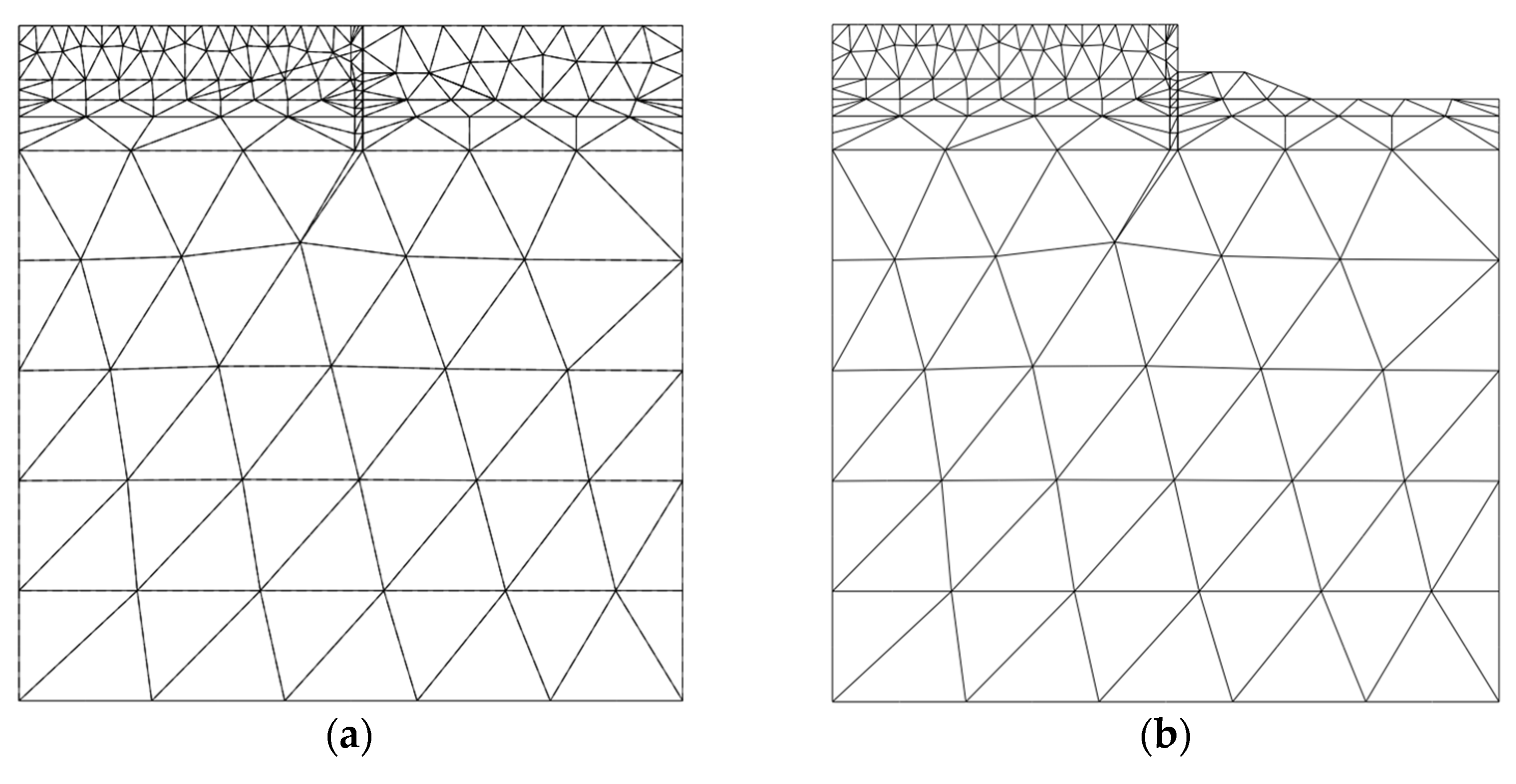
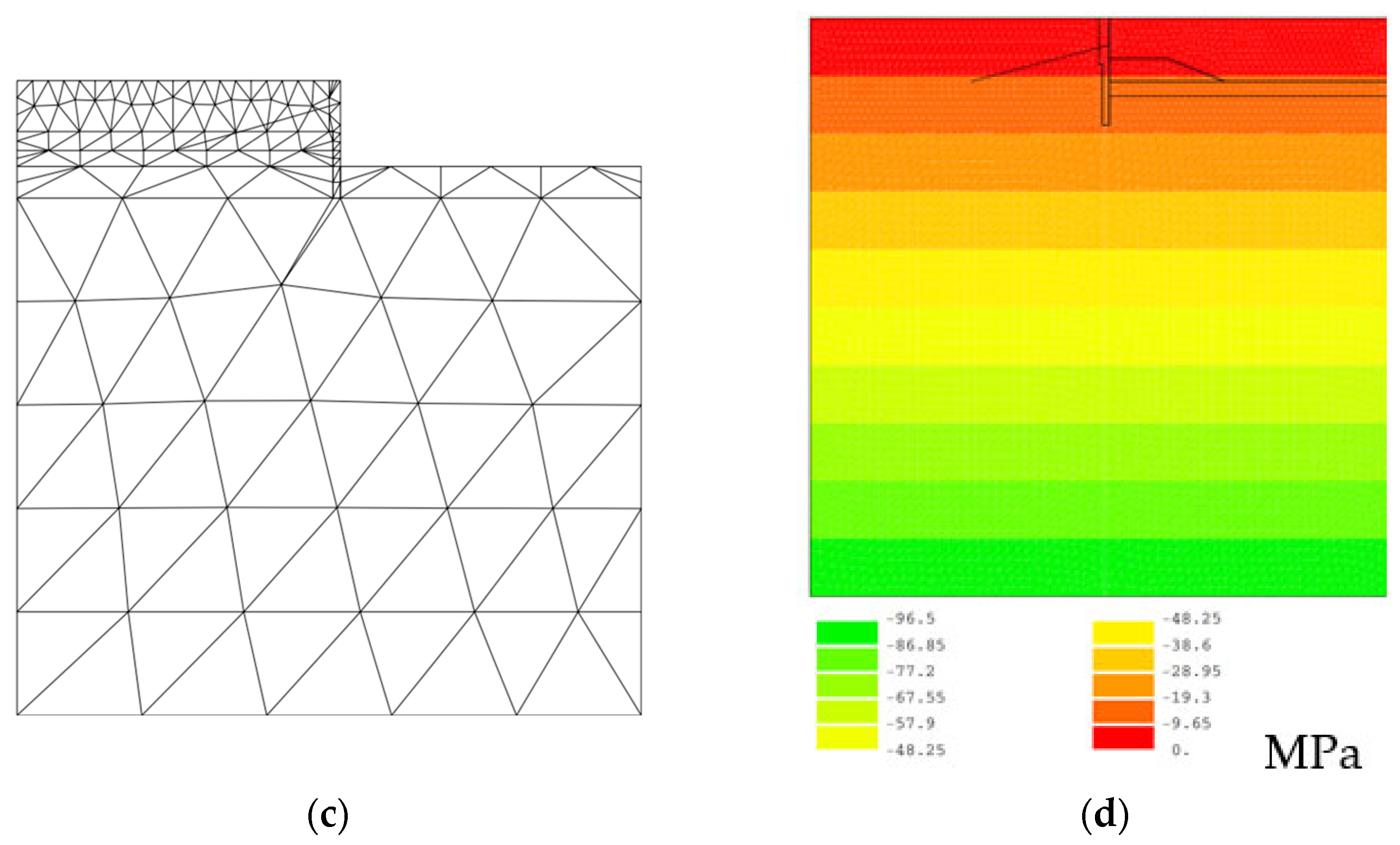
Regarding the changes in the mechanical behavior of the railway track surface, the surrounding ground surface, and the retaining piles caused by the successive excavation of the gravel layer, this study first used a two-dimensional finite element program to simulate the excavation sequence. The calculation’s contents mainly included: (a) the first stage of excavation to GL -3.5 m below the surface and (b) the second stage of excavation to GL -6.75 m below the surface. In the 2D finite element analysis, the mesh used for the calculation contained six groups (three soil layers, the excavation, and the support), 4566 nodes, 2210 elements (2209 triangles with 6 points, T6 elements, and 1 bar element), as shown in
Figure 7.
Figure 7a shows the finite element mesh of the completed vertical wall and retaining pile and of the not-yet-excavated gravel layer. In addition, the finite element meshes of the first-stage excavation and the second-stage excavation are shown in
Figure 7b,c, respectively.
Figure 7d shows the iso-value of the initial vertical stress of the three layers calculated by the finite element program, that is, the simulation stage of the in situ stress.
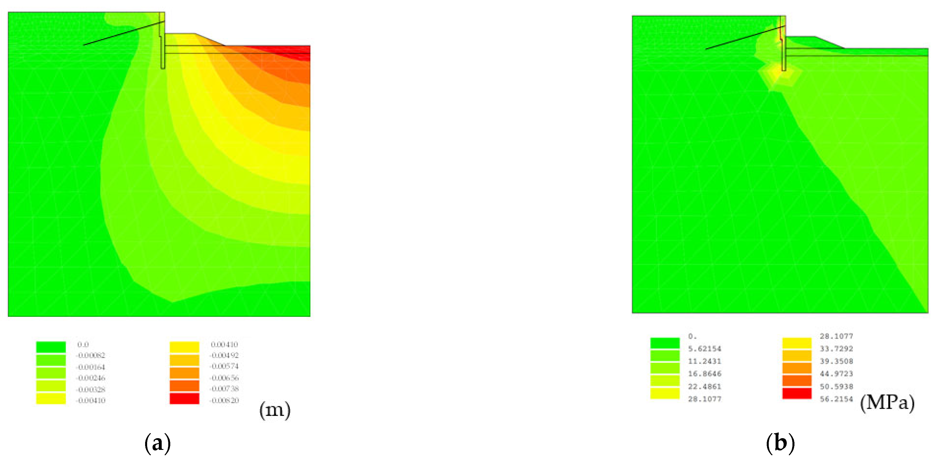
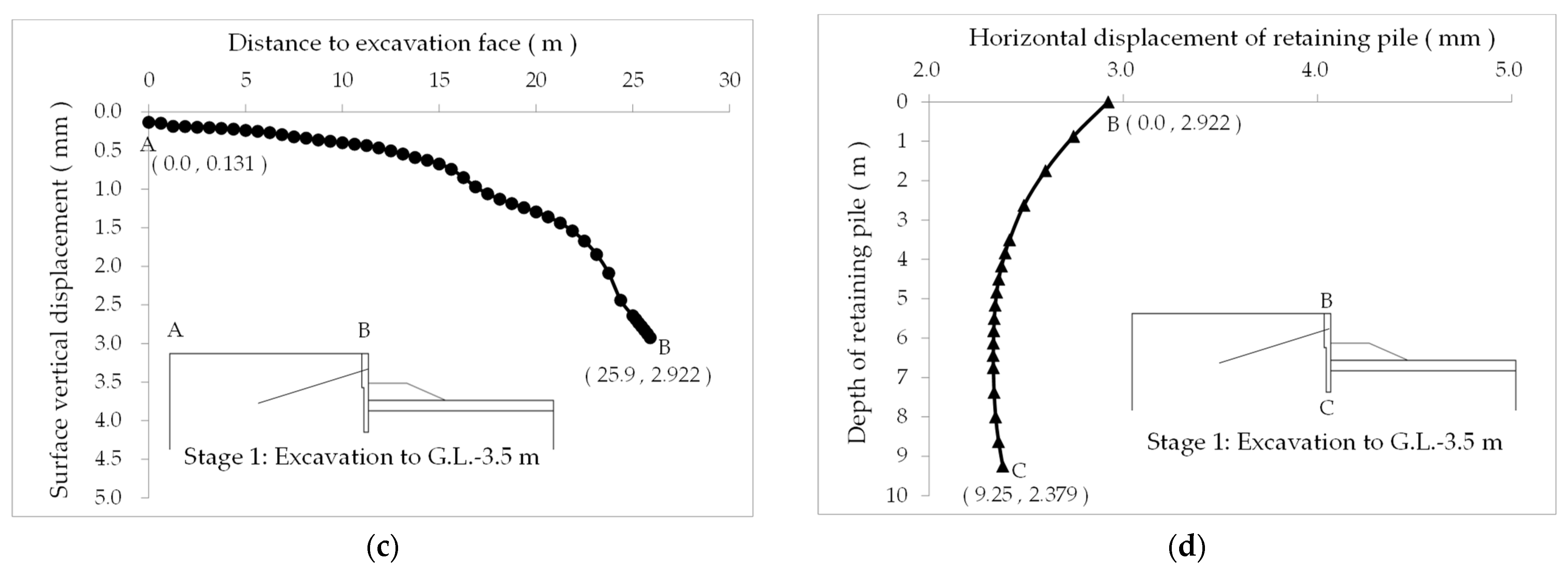
Figure 8a shows the iso-value of the total displacement after the calculation of the excavation in the first stage. It can be found that the displacement of the railway track surface and the surrounding surface caused by the stratum excavation changed; in particular, the surrounding surface is more obvious. The track surface changed less due to the support of the retaining piles.
Figure 8c shows the vertical displacement distribution of the railway track surface along the AB line, while
Figure 8d shows the horizontal displacement distribution of the retaining pile along the BC line, and the displacement at point B adjacent to the railway track’s side was 2.922 mm. In addition, the maximum subsidence at the center of the railway track (about 5 m away from the excavation surface) was 1.9 mm. From
Figure 8b, it can be seen that there was a large deviatoric stress around the vertical wall and the bottom end of the retaining pile.
Similarly, after continuing the calculation of the second-stage excavation, the displacement changes in the railway track surface and the surrounding ground surface, as well as the deviatoric stress at the bottom of the vertical walls and the retaining pile, continued to change, and the increases in the values are shown in
Figure 9a,b.
Figure 9c shows the vertical displacement distribution of the railway track surface along the AB line, while
Figure 9d shows the horizontal displacement distribution of the retaining pile along the BC line, and the displacement increased to 4.761 mm at point B adjacent to the railway track’s edge. In addition, the maximum subsidence at the center of the railway track (about 5 m away from the excavation surface) was 2.0 mm.
4. Comparison between the Monitoring Data and the Results of 3D FEM Analysis
4.1. Three-Dimensional Finite Element Analysis of the Excavation and Retaining Piles
The assumptions of the 3D finite element analysis included the following: (1) The initial stress was isotropic, (2) the gravel layer was homogeneous and independent of time, and (3) the influence of groundwater was not considered. Since deep-well pumping was implemented in the work area and the pre-precipitation water level was lower than the excavation surface, the pore water pressure was not considered in this study. Regarding the setting of the boundary of the 3D finite element analysis, the movement direction of the boundary was limited by the roller, and the XYZ range was 50 m in each direction. The 3D finite element mesh used a total of 9 element groups, 528 hexahedral MTH20 elements, and 2977 nodes, as shown in
Figure 10a–c. The mesh diagrams of the first-stage stratum excavation to G.L.-3.5 m and the second-stage stratum excavation to G.L.-6.75 m are shown in
Figure 10d,e, respectively.
The numerical simulation and analysis of this research adopted a 3D finite element program that was developed in the laboratory, and its main calculation content and steps included three main parts: (1) the pre-processing program, (2) main calculation program, and (3) post-processing program. The calculation steps and contents were as follows: (1) pre-processing program: preparing calculation data, including the calculation range, automatically generated 3D excavation and support meshes, calculation matrix optimization and re-node numbering, inputting parameters according to the selected composition mode, and defining each module group, boundary conditions, the use of the initial stress method, the number of iterative operations, and the allowable accuracy; (2) main calculation program: reading data and related calculations, including the parameters of each group of elements, the total domain coordinate value of each node, the parameters of the constitutive law of each module, the degree of freedom of each node, the state of force, the number of repeated operations, the allowable accuracy value, etc.; (3) post-processing programs: visual interface processing and drawing output, including the iso-value of the displacement distribution map of the x, y, and z directions and total displacement, the iso-value of the stress distribution map of the principal stress and deviatoric stress, the distribution map of the stress field and displacement field, etc.
In the 3D finite element program, to simulate the construction sequence for the retaining piles during the excavation, for the numerical simulation of the excavation of the gravel layer, the elements in the excavation area were first removed, and then the equivalent reverse was applied via nodal forces on the excavation surface. The simulation steps for the excavation and support were as follows: (1) calculating the initial stress state of the overall element (the stress distribution map of the vertical covering soil of the stratum); (2) defining the excavation range and setting its stiffness matrix to 0; (3) the obtained initial stress of the excavation face was applied to the excavation face with the reverse equivalent nodal force; (4) application of equivalent nodal forces to predetermined values; (5) iterative convergence of the equivalent nodal force on the excavation surface to 0 and calculation of the stress–strain state of the overall element after excavation; (6) restoring the support structure mesh and applying gravity; (7) carrying out the next round of the excavation calculation. The 3D finite element mesh of the excavation and support (as shown in
Figure 10) showed the simulation method for the construction sequence of each excavation and support unit.
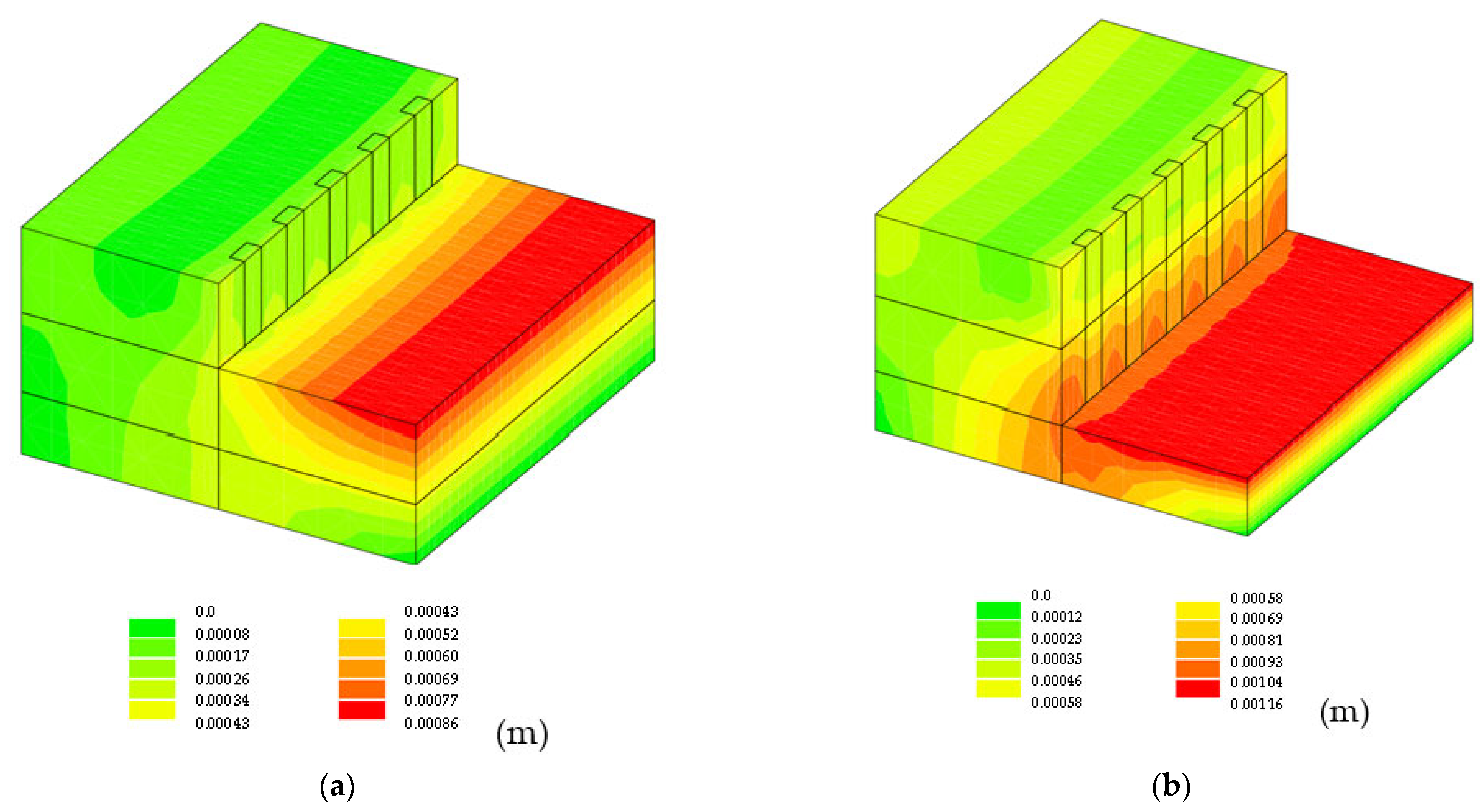
The simulation of the construction sequence of the stratum excavation and the retaining piles’ support was divided into three steps, namely, (1) the initial stress application of the stratum, (2) the first-stage excavation of the stratum to G.L.-3.5 m, and (3) the second-stage excavation of the stratum to G.L.-6.75 m. The results of the calculation with the 3D finite element program showed the total displacement distributions of the first and second stages of the excavation, which are shown in
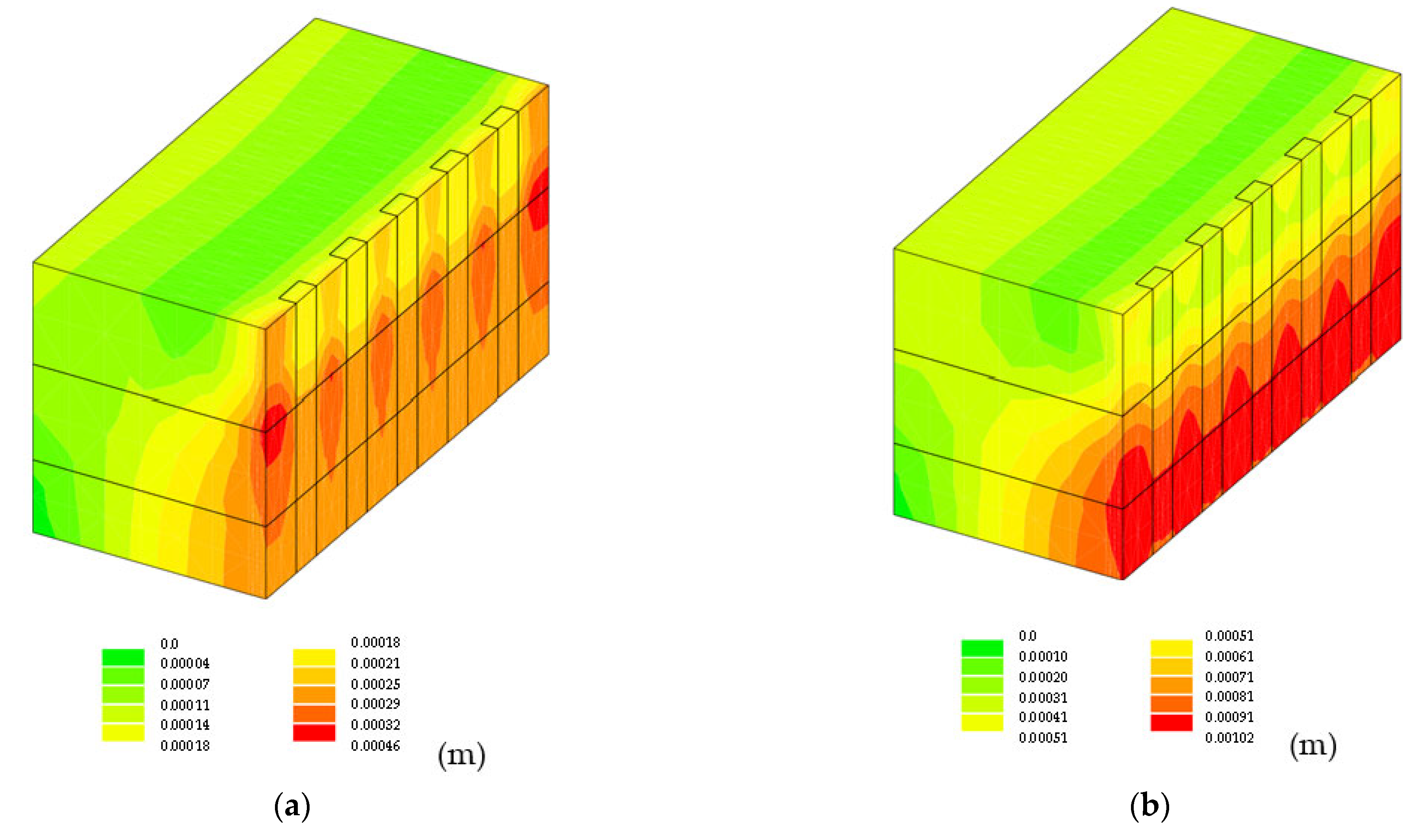
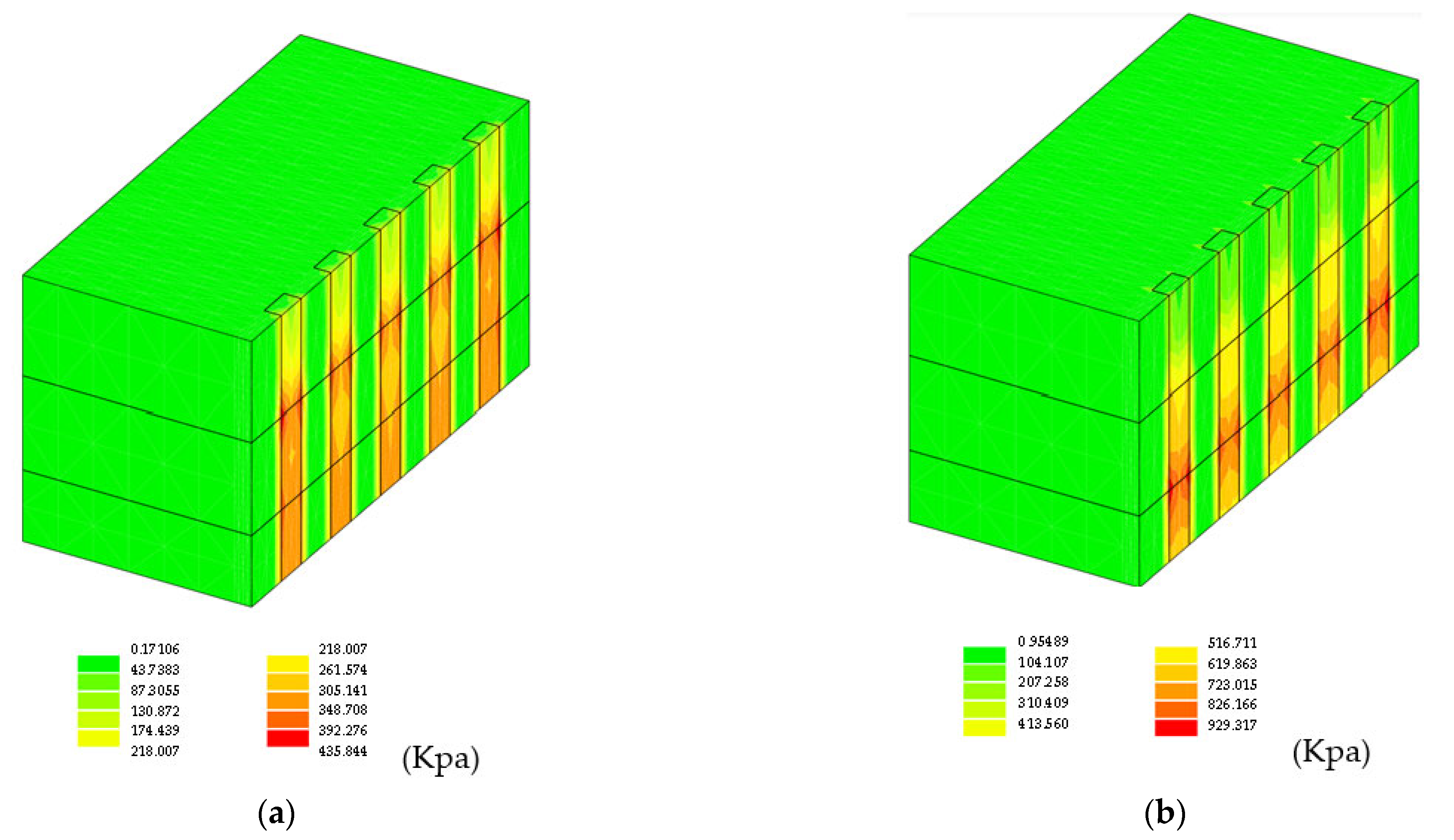
Figure 11a,b, respectively. It can be found from the figure that the action of the retaining piles was able to reduce the stratum displacement, and the unsupported excavation area produced more displacement. In addition, the distribution diagrams of the displacement and the second deviatoric stress of the retaining pile are shown in
Figure 12 and
Figure 13, respectively. As shown in the figures, there was no plastic zone in the gravel layer.
4.2. Comparison with the Monitoring Data of the Railway Track Subsidence Point
The railway track subsidence point (SR) was installed on the track surface to understand the amount of subsidence caused by the excavation. Since the construction range of the retaining column was close to the railway track, the warning value and the action value of the vertical and horizontal displacements according to the design specifications were 5 and 7 mm, respectively. In order to avoid any unexpected situations on the railway track, the monitoring system used 24 h automatic monitoring, and if the system’s settings reached a warning value, it would send a text message to notify the construction unit.
As shown in the left part of
Figure 4, there were a total of nine railway track subsidence points in the south area, of which the three circled in red were taken as examples, and their numbers were SR-003, SR-006, and SR-007.
Table 2 shows the observation data of the railway track subsidence points at various construction stages when the adjacent railway tracks were used as retaining piles. From the observation data in the table, it can be seen that the maximum value of the railway track subsidence points appeared during the construction of the retaining piles and the first and second stages of excavation. The maximum value was 3.92 mm and did not exceed the warning value (5 mm).
After the pouring of the concrete for the vertical wall and retaining piles was completed, the subsidence value changed from a negative value to a positive value, and the subsidence amount was gradually transferred from the adjacent rail side to the excavation surface. In addition, the track subsidence values of the first and second stages of excavation had an obvious trend of increasing toward the excavation surface. This monitoring-recorded phenomenon showed a consistent trend, as previously described in the 3D finite element analysis results in
Figure 11.
The results of the 3D finite element analysis and the monitoring data (SR) were compared, as shown in
Figure 14. For the results of the subsidence analysis along the railway track’s direction (the AB direction in
Figure 14a), in the first stage of excavation (GL-3.5 m), the maximum displacement of the ground in the numerical analysis was 2.27 mm, and the maximum subsidence in the monitoring data was 2.38 mm. In addition, in the second stage of excavation (G.L.-6.75 m), the computational and monitoring values were 2.53 and 2.58 mm, respectively. Moreover, for the results of the subsidence analysis perpendicular to the direction of the railway track (the CD direction in
Figure 14b), in the first stage of excavation, the maximum displacement of the ground in the numerical analysis was 2.19 mm, and the maximum subsidence in the monitoring data was 2.31 mm. In addition, in the second stage of excavation, the computational and monitoring values were 2.42 and 2.5 mm, respectively.
4.3. Comparison with the Monitoring Data of an Inclinometer
In this study, an inclinometer (SID) was installed in conjunction with the construction of the retaining piles to measure the lateral displacement of the ground and the retaining piles after excavation. There were three inclination instruments (numbered SID-01, SID-02, and SID-03 respectively) buried in the south area of this case, and the buried depth of the retaining piles was 9.25 m.
Table 3 shows the data observed for the maximum displacement measured by the inclinometer (SID) in each construction stage in the south area. From the observation data in the table, it can be seen that the maximum value measured by the inclinometer appeared during the pouring of the concrete for the base plate in the south area. The maximum value was 1.07 mm and did not exceed the warning value (45 mm). It was observed that the retaining wall’s structure was safe and stable during the monitoring period.
A comparison between the results of the 3D finite element analysis and the monitoring data of an inclinometer (SID-002) is shown in
Figure 15. For the subsidence results perpendicular to the direction of the railway track (the CD direction in
Figure 15a), in the first stage of excavation, the maximum displacement of the ground in the numerical analysis was 0.2 mm, and the maximum subsidence of the monitoring data was 0.28 mm. In addition, in the second stage of excavation, the computational and monitoring values were 0.42 and 0.55 mm, respectively. Moreover, for the results of the analysis along the embedment direction of the retaining piles (the EF direction in
Figure 15b), in the first stage of excavation, the maximum displacement of the retaining pile in the numerical analysis was 0.28 mm, and the maximum displacement in the monitoring data (SID-002) was 0.29 mm. In addition, in the second stage of excavation, the computational and monitoring values were 0.93 and 0.95 mm, respectively. It could be seen that the computational values from the 3D finite element analysis and the monitoring values showed a very consistent distribution trend.
The gravel layer in the construction area of this study not only had good self-support and a high shear strength, but it also had a gravel content of at least 75%. Under the condition of considering the live load of trains running on the railway and protecting the ballast of the track bed adjacent to the railway track, a temporary vertical wall with a depth of 4 m was added to the design as an early retaining wall measure, and it was connected with the subsequent construction of the retaining piles to increase the confinement capabilities. Therefore, the results of the comparison of the monitoring data and 3D finite element analysis showed that the displacement of the retaining wall was within a safe range and was stable.
5. Conclusions
Through the introduction of the engineering background, a description of the processes of 2D and 3D numerical analyses, the verification of calculations, and a comparison with monitoring data, the following conclusions can be drawn:
- (1)
This study adopted a 3D finite element analysis program developed by a laboratory, and its contents included a pre-processing program, central calculation program, and post-processing program.
- (2)
The results of a comparison of the 3D finite element analysis and monitoring values showed that the method of constructing retaining piles in this study was able to overcome the traffic safety impact of the adjacent railway tracks caused by the excavation of the gravel layer, and it is, indeed, a construction method with a high level of safety.
- (3)
The results of the comparison between the 3D finite element analysis and monitoring values, such as the values from an inclinometer (SID) and railway track subsidence points (SRs), were similar and far from the warning value.
- (4)
The results of this study show the feasibility and convenience of 3D numerical analysis. It is suggested that in the design stage, the use of a 3D simulation analysis is more in line with the actual construction conditions.
According to the results of this study, after pumping water, the gravel layer had the characteristics of good self-support and high shear strength. In general, on construction sites in the Taichung area, ground-retaining facilities that are commonly used in deep excavations undergo a construction method that uses the mechanical excavation of retaining piles, which should be suitable for this gravel layer. In addition, this construction method for retaining piles has the advantages of low noise, low dust pollution, less vibration during construction, etc., and it is currently the most important construction method for retaining structures for excavations in urban areas. The key to the success of this project lies in the use of mechanical excavation and the use of vertical walls, retaining piles, and tie-beams as the main supporting members when excavating the gravel layer adjacent to the railway track. The results of this study will be provided as a future reference for related projects.
Author Contributions
Methodology, supervision, writing—original draft, Y.-L.L.; software programming, computation, P.-W.H. and C.-M.L.; formal analysis, W.-K.H., C.-H.M. and M.-Y.L. All authors have read and agreed to the published version of the manuscript.
Funding
This research received no external funding.
Institutional Review Board Statement
Not applicable.
Informed Consent Statement
Not applicable.
Data Availability Statement
Not applicable.
Conflicts of Interest
The authors declare no conflict of interest.
References
- Chang, S.S.L. Subsurface Geologic Study of the Taichung Basin, Taiwan. Petro. Geol. Taiwan 1971, 8, 21–45. [Google Scholar]
- Lin, S.Y.; Lin, J.Y.; Chung, T.S.; Wu, S.M. The Study of Retaining Columns Method for Deep Basement Excavations of High-Rise Buildings in Taichung City. In Proceedings of the International Conference on Urban Engineering in Asian Cities in the 21st Century, Bangkok, Thailand, 20–23 November 1996. [Google Scholar]
- Mana, A.I.; Clough, G.W. Prediction of Movements for Braced Cuts in Clay. J. Geotech. Eng. Div. 1981, 107, 759–777. [Google Scholar] [CrossRef]
- Ou, C.-Y.; Hsieh, P.-G.; Chiou, D.-C. Characteristics of ground surface settlement during excavation. Can. Geotech. J. 1993, 30, 758–767. [Google Scholar] [CrossRef]
- Hsieh, P.-G.; Ou, C.-Y. Shape of ground surface settlement profiles caused by excavation. Can. Geotech. J. 1998, 35, 1004–1017. [Google Scholar] [CrossRef]
- Tsai, L.J.; Hsu, W.K.; Lin, M.Y.; Lee, Y.L. Discussion on the mechanical behavior of the retaining piles applied to a gravel layer. In Proceedings of the 16th Symposium on Geotechnical Engineering, Kaohsiung, Taiwan, 28 September 2015. [Google Scholar]
- Chang, K.-T.; Kang, Y.-M.; Ge, L.; Cheng, M.-C. Mechanical Properties of Gravel Deposits Evaluated by Nonconventional Methods. J. Mater. Civ. Eng. 2015, 27, 04015032. [Google Scholar] [CrossRef] [Green Version]
- Chu, B.-L.; Jou, Y.-W.; Weng, M.-C. A constitutive model for gravelly soils considering shear-induced volumetric deformation. Can. Geotech. J. 2010, 47, 662–673. [Google Scholar] [CrossRef]
- Lin, P.-S.; Yang, L.-W.; Juang, C.H. Subgrade reaction and load-settlement characteristics of gravelly cobble deposits by plate-load tests. Can. Geotech. J. 1998, 35, 801–810. [Google Scholar] [CrossRef]
- Shahien, M.M.; Farouk, A. Estimation of deformation modulus of gravelly soils using dynamic cone penetration tests. Ain Shams Eng. J. 2013, 4, 633–640. [Google Scholar] [CrossRef] [Green Version]
- Duong, T.V.; Tang, A.M.; Cui, Y.-J.; Trinh, V.N.; Dupla, J.-C.; Calon, N.; Canou, J.; Robinet, A. Effects of fines and water contents on the mechanical behavior of interlayer soil in ancient railway sub-structure. Soils Found. 2013, 53, 868–878. [Google Scholar] [CrossRef] [Green Version]
- Liyanapathirana, D.; Nishanthan, R. Influence of deep excavation induced ground movements on adjacent piles. Tunn. Undergr. Space Technol. 2016, 52, 168–181. [Google Scholar] [CrossRef]
- Uge, B.U.; Guo, Y. Deep Foundation Pit Excavations Adjacent to Disconnected Piled Rafts: A Review on Risk Control Practice. Open J. Civ. Eng. 2020, 10, 270–300. [Google Scholar] [CrossRef]
- Desai, C.; Siriwardane, H. Numerical Models for Track Support Structures. J. Geotech. Eng. Div. 1982, 108, 461–480. [Google Scholar] [CrossRef]
- Hall, L. Simulations and analyses of train-induced ground vibrations in finite element models. Soil Dyn. Earthq. Eng. 2003, 23, 403–413. [Google Scholar] [CrossRef]
- Cui, M.; Fu, X.; Hu, L.; Liu, H. Application of Secant Piles for Excavation Pit in Complicated Environment. IOP Conf. Series Earth Environ. Sci. 2021, 719, 032017. [Google Scholar] [CrossRef]
- Bekdaş, G.; Arama, Z.A.; Kayabekir, A.E.; Geem, Z.W. Optimal Design of Cantilever Soldier Pile Retaining Walls Embedded in Frictional Soils with Harmony Search Algorithm. Appl. Sci. 2020, 10, 3232. [Google Scholar] [CrossRef]
- Han, J.-Y.; Zhao, W.; Chen, Y.; Jia, P.-J.; Guan, Y.-P. Design Analysis and Observed Performance of a Tieback Anchored Pile Wall in Sand. Math. Probl. Eng. 2017, 2017, 8524078. [Google Scholar] [CrossRef] [Green Version]
- Wong, S.Y.; Kok, S.T.; Choong, W.K.; Mohamed, A.A. Modelling and Validation of 3D FEM for Laterally Loaded Single. Int. J. Integr. Eng. 2018, 10. [Google Scholar] [CrossRef]
- Le, N.T.; Ho Chi Minh City University of Transport. 3D Finite Element Analysis of Pile Behavior Inside the Deep Excavation in Soft Soil. Int. J. Eng. Res. 2021, 10. [Google Scholar] [CrossRef]
- Soomro, M.A.; Mangnejo, D.A.; Bhanbhro, R.; Memon, N.A.; Memon, M.A. 3D finite element analysis of pile responses to adjacent excavation in soft clay: Effects of different excavation depths systems relative to a floating pile. Tunn. Undergr. Space Technol. 2019, 86, 138–155. [Google Scholar] [CrossRef]
- Zhang, R.; Goh, A.T.C.; Zhang, W. 3D numerical analysis of passive pile groups adjacent to deep braced excavation in soft clay. Int. J. Civ. Infrastruct. 2020, 3, 7–14. [Google Scholar] [CrossRef]
- Griffiths, D.V.; Marquez, R.M. Three-dimensional slope stability analysis by elasto-plastic finite elements. Geotechnique 2007, 57, 537–546. [Google Scholar] [CrossRef]
- Hung, H.; Chen, G.; Yang, Y. Effect of railway roughness on soil vibrations due to moving trains by 2.5D finite/infinite element approach. Eng. Struct. 2013, 57, 254–266. [Google Scholar] [CrossRef]
- Galvín, P.; Romero, A.; Domínguez, J. Fully three-dimensional analysis of high-speed train–track–soil-structure dynamic interaction. J. Sound Vib. 2010, 329, 5147–5163. [Google Scholar] [CrossRef]
- Connolly, D.; Giannopoulos, A.; Forde, M. Numerical modelling of ground borne vibrations from high speed rail lines on embankments. Soil Dyn. Earthq. Eng. 2013, 46, 13–19. [Google Scholar] [CrossRef] [Green Version]
- Çelebi, E.; Göktepe, F. Non-linear 2-D FE analysis for the assessment of isolation performance of wave impeding barrier in reduction of railway-induced surface waves. Constr. Build. Mater. 2012, 36, 1–13. [Google Scholar] [CrossRef]
- Berggren, E.G.; Kaynia, A.M.; Dehlbom, B. Identification of substructure properties of railway tracks by dynamic stiffness measurements and simulations. J. Sound Vib. 2010, 329, 3999–4016. [Google Scholar] [CrossRef]
- Ju, S.-H.; Lin, H.-T. Analysis of train-induced vibrations and vibration reduction schemes above and below critical Rayleigh speeds by finite element method. Soil Dyn. Earthq. Eng. 2004, 24, 993–1002. [Google Scholar] [CrossRef]
- Thach, P.-N.; Liu, H.-L.; Kong, G.-Q. Vibration analysis of pile-supported embankments under high-speed train passage. Soil Dyn. Earthq. Eng. 2013, 55, 92–99. [Google Scholar] [CrossRef]
- Owen, D.R.J.; Hinton, E. Finite Elements in Plasticity-Theory and Practice; Pineridge Press: Swansea, UK, 1980; pp. 215–231. [Google Scholar]
Figure 1.
Scheme of the excavation and support system of Taichung Station.
Figure 1.
Scheme of the excavation and support system of Taichung Station.
Figure 2.
Diagram of the construction sequence of the excavation of the gravel layer, the vertical wall, and the retaining pile.
Figure 2.
Diagram of the construction sequence of the excavation of the gravel layer, the vertical wall, and the retaining pile.
Figure 3.
Construction photos of this project: (a) concrete pouring work for the vertical wall; (b) completed retaining piles and tie-beams; (c) ground anchor.
Figure 3.
Construction photos of this project: (a) concrete pouring work for the vertical wall; (b) completed retaining piles and tie-beams; (c) ground anchor.
Figure 4.
Distribution map of the monitoring equipment installed in the station.
Figure 4.
Distribution map of the monitoring equipment installed in the station.
Figure 5.
Surface loading of the design.
Figure 5.
Surface loading of the design.
Figure 6.
Borehole log for the site under consideration.
Figure 6.
Borehole log for the site under consideration.
Figure 7.
Mesh diagram for the 2D finite element analysis: (a) original mesh that was not yet excavated; (b) first stage of excavation; (c) second stage of excavation; (d) iso-value of the initial vertical stress.
Figure 7.
Mesh diagram for the 2D finite element analysis: (a) original mesh that was not yet excavated; (b) first stage of excavation; (c) second stage of excavation; (d) iso-value of the initial vertical stress.
Figure 8.
Results obtained with the 2D FEM analysis of the first-stage excavation: (a) iso-value of the total displacement; (b) iso-value of the second deviatoric stress; (c) vertical surface displacement along the AB line; (d) horizontal displacement of the retaining pile along the BC line.
Figure 8.
Results obtained with the 2D FEM analysis of the first-stage excavation: (a) iso-value of the total displacement; (b) iso-value of the second deviatoric stress; (c) vertical surface displacement along the AB line; (d) horizontal displacement of the retaining pile along the BC line.
Figure 9.
Results obtained with the 2D FEM analysis of the second-stage excavation: (a) iso-value of the total displacement; (b) iso-value of the second deviatoric stress; (c) vertical surface displacement along the AB line; (d) horizontal displacement of the retaining pile along the BC line.
Figure 9.
Results obtained with the 2D FEM analysis of the second-stage excavation: (a) iso-value of the total displacement; (b) iso-value of the second deviatoric stress; (c) vertical surface displacement along the AB line; (d) horizontal displacement of the retaining pile along the BC line.
Figure 10.
Mesh of the 3D finite element analysis: (a) borders and dimensions; (b) gravel layer and retaining piles; (c) retaining piles; (d) first-stage stratum excavation; (e) second-stage stratum excavation.
Figure 10.
Mesh of the 3D finite element analysis: (a) borders and dimensions; (b) gravel layer and retaining piles; (c) retaining piles; (d) first-stage stratum excavation; (e) second-stage stratum excavation.
Figure 11.
Iso-value of the total displacement obtained with the 3D FEM analysis for (a) the first-stage stratum excavation and (b) the second-stage stratum excavation.
Figure 11.
Iso-value of the total displacement obtained with the 3D FEM analysis for (a) the first-stage stratum excavation and (b) the second-stage stratum excavation.
Figure 12.
Iso-value of the total displacement of the retaining piles obtained with the 3D FEM analysis for (a) the first-stage stratum excavation and (b) the second-stage stratum excavation.
Figure 12.
Iso-value of the total displacement of the retaining piles obtained with the 3D FEM analysis for (a) the first-stage stratum excavation and (b) the second-stage stratum excavation.
Figure 13.
Iso-value of the second deviatoric stress of the retaining piles obtained with the 3D FEM analysis for (a) the first-stage stratum excavation and (b) the second-stage stratum excavation.
Figure 13.
Iso-value of the second deviatoric stress of the retaining piles obtained with the 3D FEM analysis for (a) the first-stage stratum excavation and (b) the second-stage stratum excavation.
Figure 14.
Comparison of 3D FEM analysis results with the monitoring data on railway track subsidence (SR) for the total displacement of the excavation in stages 1 and 2: (a) along the AB direction; (b) along the CD direction.
Figure 14.
Comparison of 3D FEM analysis results with the monitoring data on railway track subsidence (SR) for the total displacement of the excavation in stages 1 and 2: (a) along the AB direction; (b) along the CD direction.
Figure 15.
Comparison of the results of the 3D FEM analysis with the inclinometer monitoring data (SID-002) in the retaining piles for the total displacement of the excavation in stages 1 and 2: (a) along the CD direction; (b) along the EF direction.
Figure 15.
Comparison of the results of the 3D FEM analysis with the inclinometer monitoring data (SID-002) in the retaining piles for the total displacement of the excavation in stages 1 and 2: (a) along the CD direction; (b) along the EF direction.
Table 1.
Physical properties of each layer for the numerical computation.
Table 1.
Physical properties of each layer for the numerical computation.
Layer
Number | Depth
(m) | Description
(USCS) 1 | SPT,
N Value 2 | Cohesion,
c (kN/m2) | Friction
Angle,
ϕ (Degree) | Unit
Weight
γt(kN/m3) |
|---|
| 1 | 0.00–1.13 | Backfill | 4 | 0.0 | 29 | 1.97 |
| 2 | 1.13–3.50 | Yellow sandy silt | 2.5 | 0.1 | 25 | 1.80 |
| 3 | 3.50–30.0 | Gravel | >100 | 0.0 | 35 | 2.10 |
Table 2.
Subsidence monitoring data of the railway track (SR) in each construction stage in the south area.
Table 2.
Subsidence monitoring data of the railway track (SR) in each construction stage in the south area.
| Construction Stage | SR-003
(mm) | SR-006
(mm) | SR-009
(mm) |
| Water removal operation and vertical wall construction | 3.5 | 3.58 | 3.92 |
| Construction of retaining piles, and during the first and second stages of excavation | 3.8 | 3.88 | 3.94 |
| Pre-stressed ground anchor construction | 3.6 | 3.29 | 3.72 |
| Foundation floor construction | 2.72 | 3.08 | 2.57 |
Table 3.
Maximum displacement measured by the inclinometers (SID) in each construction stage in the south area.
Table 3.
Maximum displacement measured by the inclinometers (SID) in each construction stage in the south area.
| Construction Stage | SID-001
(mm) | SID-002
(mm) | SID-003
(mm) |
|---|
| Assembly of the tie-beam formwork for retaining piles in the central area and construction of steel piles in the south area | 0.17 | 0.42 | 0.42 |
| Pre-stressed ground anchors for retaining piles | 0.67 | 0.50 | 0.70 |
| Pre-stressed ground anchors for steel piles | 0.76 | 0.54 | 0.81 |
| Pouring of concrete for the base plate in the south area | 1.07 | 0.57 | 0.91 |
| Disclaimer/Publisher’s Note: The statements, opinions and data contained in all publications are solely those of the individual author(s) and contributor(s) and not of MDPI and/or the editor(s). MDPI and/or the editor(s) disclaim responsibility for any injury to people or property resulting from any ideas, methods, instructions or products referred to in the content. |
© 2022 by the authors. Licensee MDPI, Basel, Switzerland. This article is an open access article distributed under the terms and conditions of the Creative Commons Attribution (CC BY) license (https://creativecommons.org/licenses/by/4.0/).


