


Abstract
For hybrid energy storage systems requiring efficient energy management to achieve optimal power allocation between the power battery and supercapacitor, this study proposes an optimal energy management method integrating whole-process particle swarm optimization with fuzzy logic control, which simultaneously considers braking safety and energy efficiency optimization. First, a zonal braking force distribution strategy based on the I-curve, ECE regulations curve, and front wheel lockup curve is designed to maximize energy recovery while ensuring braking safety. On this basis, a whole-process “driving–braking” fuzzy logic control strategy for power distribution is constructed, aiming at maximizing braking energy recovery efficiency and minimizing energy consumption per 100 km. The parameters of the membership functions in the fuzzy controller are optimized using the particle swarm optimization algorithm to achieve global optimization of the control process. Finally, simulation validation of the optimization results demonstrates that, compared with traditional logic threshold control under NEDC conditions, the proposed strategy improves braking energy recovery efficiency by 10.32%, reduces energy consumption per 100 km by 0.96 kWh, and decreases the peak current of the power battery by 6.4%, thereby effectively enhancing vehicle economy and extending battery lifespan.
1. Introduction
As a core solution for sustainable transportation, electric vehicles (EVs) have seen explosive growth in market ownership in recent years [1,2]. However, range anxiety remains a key bottleneck limiting their wider adoption [3,4,5]. Regenerative braking technology can recover and reuse kinetic energy during braking, thereby improving the vehicle’s energy utilization efficiency and increasing its driving range. Nevertheless, due to the relatively low power density of traction batteries, their charge and discharge rates are limited, making it difficult to efficiently absorb the instantaneous high current generated during braking. As a result, some energy is wasted because the charging speed cannot keep up, leading to relatively low energy recovery efficiency [6,7,8]. In contrast, supercapacitors offer high power density and fast charge–discharge rates, which can better match the instantaneous demands of braking energy recovery [9,10]. Therefore, research on hybrid energy regenerative braking systems based on supercapacitors is of significant value. Such systems not only improve energy utilization efficiency but also help extend the service life of traction batteries.
To fully leverage the advantages of hybrid energy storage systems (HESSs), an efficient energy management system (EMS) is essential for continuously monitoring and allocating power between the traction battery and the supercapacitor. C. K. Wai, Sadeq, T, et al. [11,12] proposed an adaptive rule-based algorithm as an energy management strategy for HESSs, which dynamically adjusts control rules in real-time according to different operating conditions. Compared with standard rule-based methods, this approach reduces battery energy consumption and extends the driving range. Adam Deptuła et al. [13] introduced an expert system based on multi-valued logic trees for EV energy consumption decision making. This system generates driving suggestions optimized for energy efficiency by considering variables such as driving cycles, vehicle speed, and ambient temperature. Hu Jie et al. [14] designed a fuzzy logic control strategy based on the wavelet transform. This strategy maintains the state of charge (SOC) of the supercapacitor within a reasonable operating range and demonstrates that the wavelet transform–fuzzy control approach can fully exploit the performance advantages of supercapacitors, improve energy recovery efficiency, reduce the peak current of the traction battery, and extend its service life. Selvakumar et al. [15] proposed a two-layer fuzzy logic controller for optimal power allocation in HESSs. The first stage pre-allocates power based on power demand and the SOC, while the second stage incorporates a vehicle speed optimization module to dynamically adjust the SOC reference value of the supercapacitor. This strategy successfully reduces the root mean square power of the battery and effectively maintains the SOC of the energy storage components within a reasonable range. Current research on energy management strategies for HESSs primarily focuses on energy recovery efficiency and economy, often neglecting the impact of braking safety. Moreover, existing studies mostly address power allocation during braking modes without considering the influence of energy consumption during driving modes, thereby failing to establish an optimal energy management strategy that covers the entire “driving–braking” process. Additionally, most energy management strategies are based on deterministic rules, which lack flexibility and struggle to adapt to complex operating conditions. In contrast, fuzzy rule-based control strategies offer advantages in robustness and stability.
This paper designs a segmented braking force distribution strategy (SBFDS) based on the I-curve, f-curve, and ECE regulations, aiming to recover as much braking energy as possible while ensuring braking safety. Building on this foundation, a whole-process particle swarm optimization–fuzzy logic control (PSO-FLC) method for the “driving–braking” cycle of hybrid energy storage electric vehicles is developed, thereby constructing a safety–efficiency co-optimized optimal energy management approach for HESSs. The main contributions of this paper are as follows:
- (1)
- Design of the SBFDS. By integrating the I-curve, ECE regulations, and f-curve, a segmented braking force distribution curve was designed to maximize energy recovery efficiency while ensuring braking stability, and a front-to-rear braking force distribution ratio formula was derived.
- (2)
- Establishment of a power-sharing control strategy for the entire drive–brake process under the segmented braking force allocation scheme that integrates safety braking and energy efficiency optimization.
- (3)
- A PSO algorithm was introduced to perform automated global optimization of fuzzy logic membership function parameters. This optimization targets both maximum braking energy recovery efficiency and minimum energy consumption per 100 km, achieving optimal power distribution for hybrid electric vehicles.
This paper is structured as follows: Section 1 establishes an experimental test bench to investigate the impact of supercapacitor power distribution ratios on energy recovery efficiency, laying the groundwork for subsequent power allocation strategies. Section 2 develops a HESS simulation model and designs an SBFDS that synergizes safety and energy efficiency. Section 3 proposes an entire process power distribution control strategy for hybrid EVs under the SBFDS, validated through simulations under NEDC conditions.
2. Hybrid Energy Storage EV Simulation Test Bench Construction
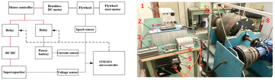
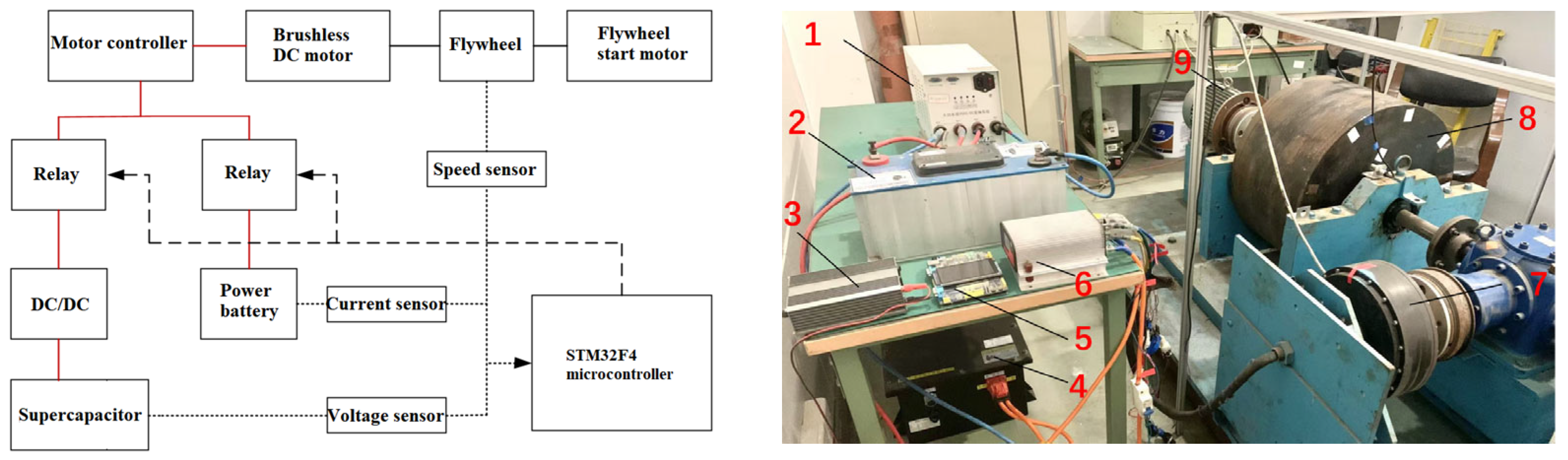
To investigate the influence of the power distribution ratio between the supercapacitor and the power battery on energy recovery efficiency during regenerative braking, this study utilized a rotating flywheel to simulate the kinetic energy of a moving electric vehicle, and an experimental test bench was constructed, as shown in Figure 1. The working principle is as follows: The flywheel starter motor drives the flywheel to rotate, simulating the kinetic energy of the vehicle in motion. Once the flywheel reaches a certain rotational speed, the starter motor is disengaged, and the inertia of the flywheel drives a brushless DC motor to rotate. The electrical energy generated by the brushless DC motor is stored in the traction battery and the supercapacitor. Simultaneously, a photoelectric sensor transmits the flywheel’s rotational speed information to a microcontroller, which calculates the magnitude of braking energy; a current sensor collects current data from the traction battery and transmits it to the microcontroller, which then calculates the SOC of the battery; a voltage sensor collects voltage data from the supercapacitor and sends it to the microcontroller for calculating the SOC of the supercapacitor. After calculating the braking energy magnitude and the SOC values of both the supercapacitor and the power battery, the microcontroller transmits on/off signals to the relay via pre-programmed logic to achieve energy allocation between the supercapacitor and the power battery. Relevant parameters of the test bench are listed in Table 1.
Figure 1.
Experimental platform for HESS. 1. DC/DC converter; 2. supercapacitor; 3. DC power supply; 4. power battery; 5. microcontroller; 6. motor controller; 7. DC brushless motor; 8. flywheel; 9. flywheel start motor.
Table 1.
Simulation of key parameters for EVs.
In the constructed hybrid energy regenerative braking experimental platform, the influence of the supercapacitor power level on energy recovery efficiency in the HESS was investigated by adjusting the proportion coefficient of supercapacitor allocated power to total power in the HESS. Five comparative experimental groups were established with values of = 0, = 0.25, = 0.5, = 0.75, and = 1. For each group, initial flywheel rotational speeds of 200 rad·min−1 and 300 rad·min−1 were used as examples. The corresponding braking energy equals the kinetic energy during flywheel rotation:
where is the flywheel braking energy, ; is the flywheel kinetic energy, ; and represent the angular velocities before and after braking, .
Calculating the corresponding braking energies using Equation (1) yields 9979 J and 22,452 J. Under conditions where the supercapacitor initial voltage is 10 V and all other experimental parameters are identical, braking energy recovery experiments were conducted for the HESS. After multiple experimental runs, the average experimental results are presented in Table 2.
Table 2.
Braking test results for different supercapacitor power allocation factors.
In Table 2, = 0 indicates that, during the energy recovery process, the power allocated to the supercapacitor is zero, meaning the supercapacitor does not participate in the operation, and energy is primarily recovered by the power battery. Conversely, = 1 signifies that all energy during the recovery process is reclaimed by the supercapacitor. Comparative analysis shows that a higher power allocation factor for the supercapacitor leads to greater braking energy recovery efficiency, indicating that incorporating the supercapacitor enhances the energy recovery efficiency of the hybrid energy system. Furthermore, as the supercapacitor assumes a larger share of the power, the overall energy recovery efficiency of the hybrid system improves. Therefore, in control strategy design, maximizing the use of the supercapacitor for braking energy recovery is highly recommended. However, the SOC of the supercapacitor must also be considered. If the SOC is too high, the supercapacitor cannot further recover braking energy, necessitating the power battery to handle recovery. If the SOC is too low, the supercapacitor cannot provide power for vehicle propulsion, thereby reducing its power allocation factor.
3. Construction of the Hybrid Energy Storage EV Simulation Model and Design of the SBFDS
3.1. Simulated Model for HESS
- (1)
- Power battery modeling
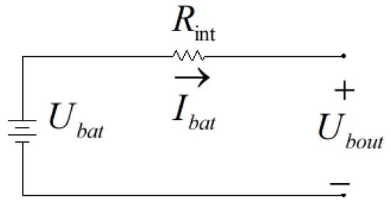
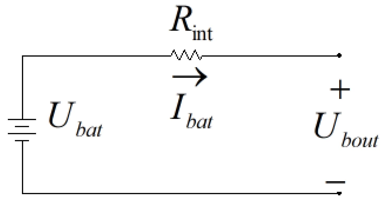
The internal resistance (Rint) model reduces complexity while ensuring long-term accuracy of the battery model [16]. The power battery is abstracted into a Rint equivalent circuit model, as shown in Figure 2.
Figure 2.
Power battery Rint model.
As shown in the figure, represents the ideal open-circuit voltage of the traction battery, denotes its ohmic internal resistance, stands for the battery current, and corresponds to the load voltage. According to Kirchhoff’s Voltage Law, the relationship between the load voltage and the open-circuit voltage is given by
The SOC of the battery is expressed as
In the equation: represents the total capacity of the battery; denotes the amount of charge already consumed; and are the lower and upper limits of , set to 20% and 95%, respectively.
- (2)
- Supercapacitor Modeling
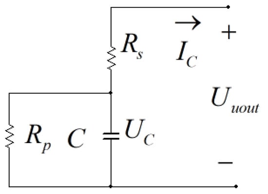
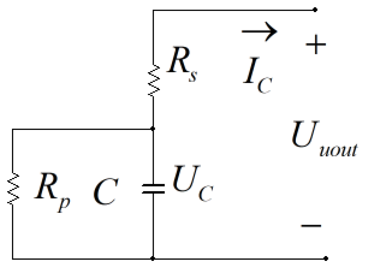
A supercapacitor is modeled using an RC equivalent circuit [16], as illustrated in Figure 3. Here, represents the open-circuit voltage of the supercapacitor and denotes its terminal voltage. In the model, stands for the ideal capacitance, is the series resistance, and represents the leakage resistance of the insulating material. Typically, the value of is relatively small, while is significantly larger, resulting in almost all of the current flowing through .
Figure 3.
Supercapacitor RC model.
According to Kirchhoff’s Voltage Law, the following expressions can be derived:
From Equations (5) and (6), it can be obtained that
The SOC of the supercapacitor exhibits a linear relationship with its terminal voltage:
where and denote the maximum and minimum operating voltages, respectively.
- (3)
- Modeling of the bidirectional DC/DC converter
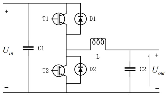
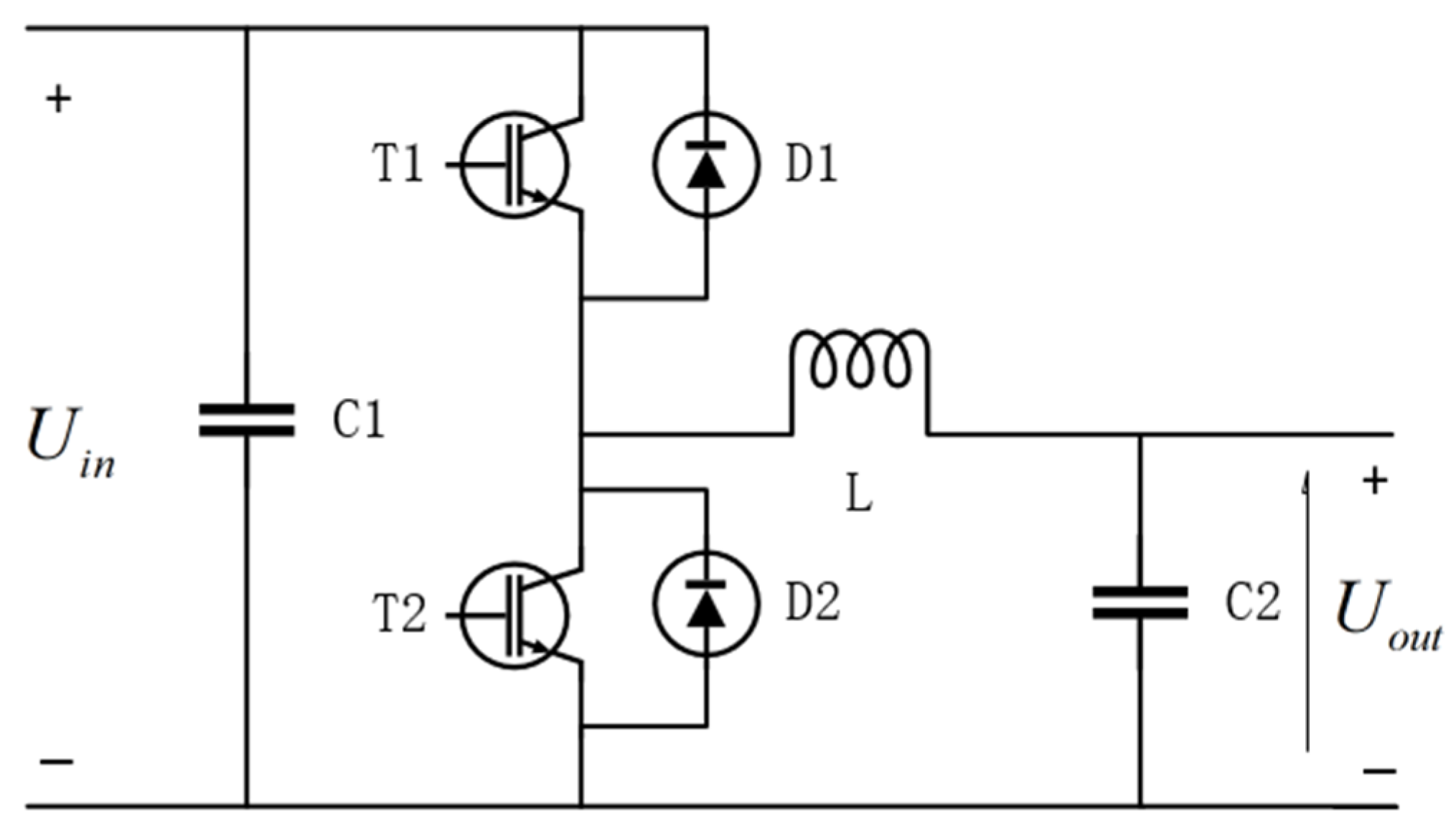
This study employs a bidirectional half-bridge converter with only one inductor, which offers higher conversion efficiency [17]. Its simplified circuit structure is shown in Figure 4.
Figure 4.
Simplified circuit of the bidirectional DC/DC converter.
In Figure 4, and represent the input voltage and output voltage, respectively, V; C denotes the capacitor in farads, F; T is the IGBT switch; D is the diode; and L represents the inductor. When energy flows from left to right, the converter operates in step-down (buck) mode, functioning equivalently as a buck DC–DC converter. Conversely, when energy flows from right to left, it operates in step-up (boost) mode, acting equivalently as a boost DC–DC converter. The transfer efficiency can be expressed as the ratio of output power to input power:
In the equation, and represent the output and input voltages, respectively, V; , denote the output and input currents, respectively, A.
3.2. Design of SBFDS
To maximize energy utilization, braking force should be allocated primarily to the front axle. The braking intensity is introduced to precisely describe the braking mode:
where is the deceleration during braking, m/s2; is gravitational acceleration, m/s2.
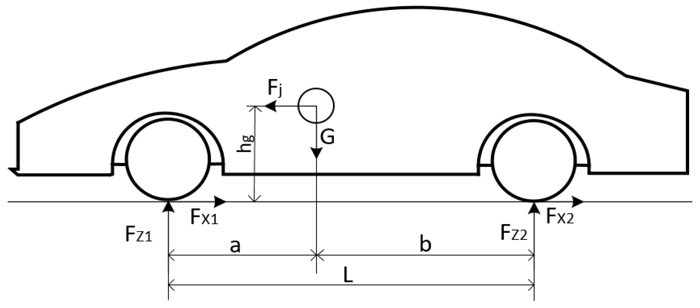
As shown in Figure 5, we consider the force conditions when a vehicle brakes on a level road surface. and represent the braking forces acting on the front and rear axles during braking, N; and denote the ground support forces on the front and rear axles, N; and are the horizontal distances from the vehicle’s center of gravity to the front and rear axles, m; is the wheelbase, m; is the height of the center of gravity, m; is the gravitational force acting on the vehicle, N.
Figure 5.
Force analysis of vehicle when braking.
During vehicle braking, three scenarios may occur: simultaneous locking of both front and rear wheels, front wheel lockup occurring first, and rear wheel lockup occurring first [18,19,20]. When both front and rear tires lock simultaneously, the vehicle exhibits optimal stability without losing control. In this case, the braking forces on the front and rear wheels must satisfy the requirements of the ideal braking force distribution curve I, whose expression is given in Equation (11). If the front wheels lock first, the vehicle loses steering capability but does not experience sideslip or tailspin, keeping the overall vehicle state under control. The expression for the front wheel lockup curve f is provided in Equation (12). In the event of rear wheel lockup first, the vehicle is prone to rear axle sideslip and tailspin, which may lead to loss of control. Therefore, such braking force distribution must be avoided. Moreover, to ensure braking safety, the ECE Committee has established regulations for vehicle braking. The expression for the corresponding ECE braking regulation curve is presented in Equation (13).
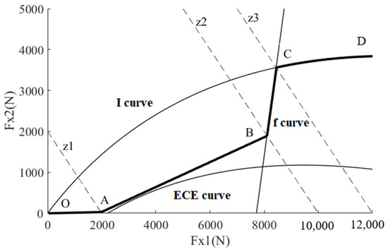
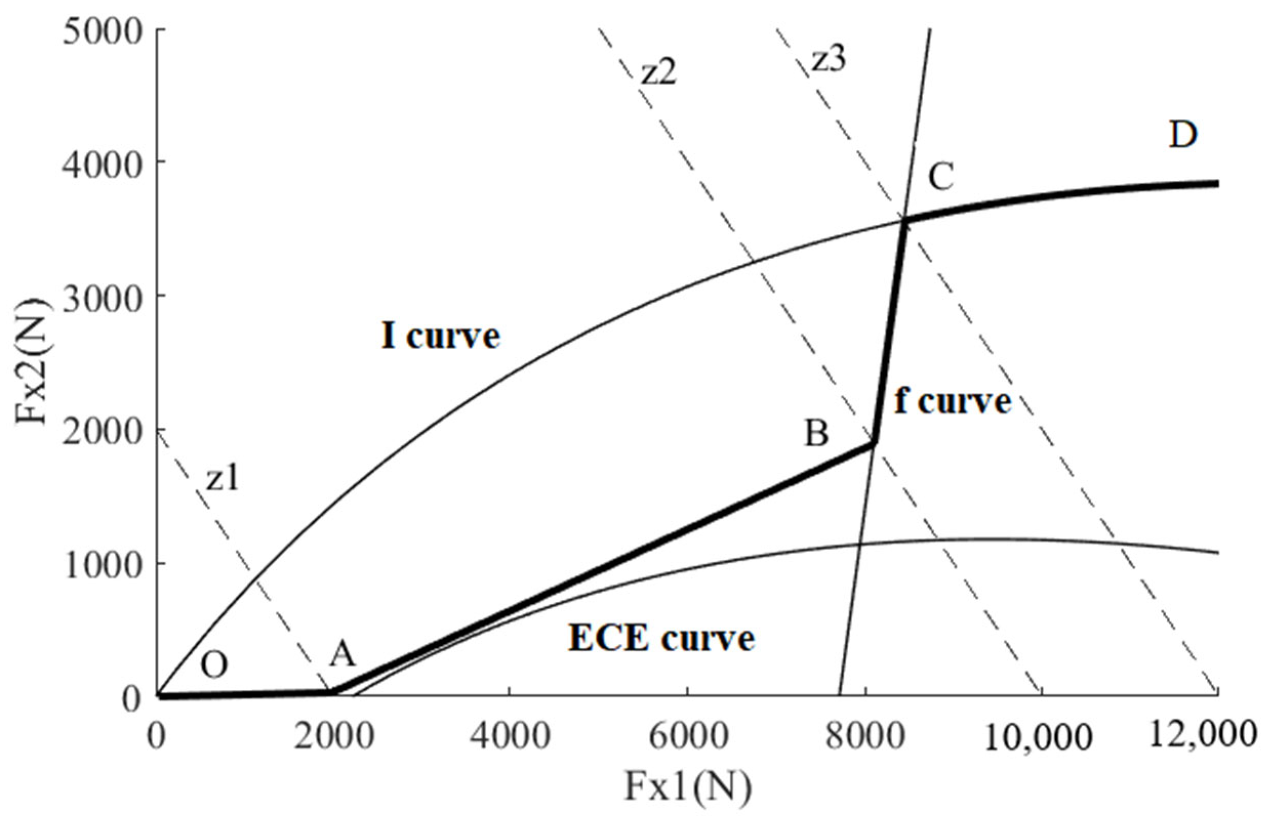
In order to maximize energy utilization, braking force should be allocated to the front axle as much as possible. This paper designs a braking force distribution strategy based on the I-curve, the ECE regulation curve, and the f-curve, as illustrated by the bold curve OABCD in Figure 6. In the figure, point A corresponds to a braking intensity of z1 = 0.125; segment AB is an approximate tangent slightly above the ECE regulation curve, with point B corresponding to a braking intensity of z2 = 0.625; point C is the intersection of the I-curve and the f-curve, corresponding to a braking intensity of z3 = 0.75.
Figure 6.
Schematic diagram of SBFDS.
When the braking intensity z 0.125, the braking force is low and regenerative braking force is generated on the front axle. The braking force is entirely provided by the front axle, with the rear wheels not participating in braking. At this point, the braking force distribution point is located within the OA zone, ensuring safe vehicle braking and improving the efficiency of regenerative braking energy recovery. The relationship between front and rear axle braking forces is given by the following equations:
Define as the ratio of front axle braking force to total braking force. The front axle braking force distribution ratio is .
When the vehicle braking intensity is 0.125 < z 0.625, the braking intensity is relatively high and the braking force increases comprehensively. The braking force distribution rises along the tangent line of the ECE regulation curve and slightly exceeds it, enabling the front axle to receive a greater proportion of the braking force. The braking force distribution point is located within the AB zone, while ensuring safety, the majority of the front axle braking force is regenerative braking force, and the rear axle friction braking force can compensate for any braking force deficiency. The front and rear axle braking force relationship is expressed as follows:
Simplifying yields the front axle braking force distribution as shown in Equation (18).
When the braking intensity is 0.625 < z ≤ 0.75, the high braking intensity causes the braking force distribution to rise along the f-curve, slightly exceeding it, resulting in a significant increase in the braking force allocated to the rear axle. When the braking force distribution point is located within the BC zone, the front axle receives braking force from both regenerative and friction braking, while the remaining braking force is provided by the rear axle’s friction braking. The relationship between front and rear axle braking forces is expressed as follows:
Simplifying yields the front axle braking force distribution as shown in Equation (21).
When the braking intensity z > 0.75, the vehicle enters emergency braking mode, and the braking force distribution must increase along the I-curve. The front and rear axle braking force distribution points lie on the I-curve, preventing rear wheel skid while ensuring the front wheels retain steering capability, maintaining the vehicle in a safe braking state. At this point, regenerative braking no longer contributes braking force, with all braking force provided by friction braking, resulting in zero braking energy recovery efficiency. The front and rear axle braking force relationships are shown in the following equations:
Simplifying yields the front axle braking force distribution as shown in Equation (24).
4. Power Allocation Control Strategy Under SBFDS
4.1. Logical Threshold Filtering Control Strategy
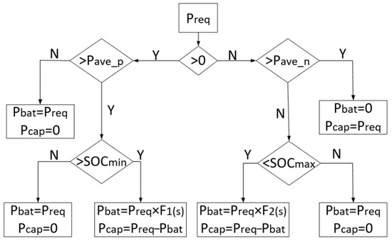
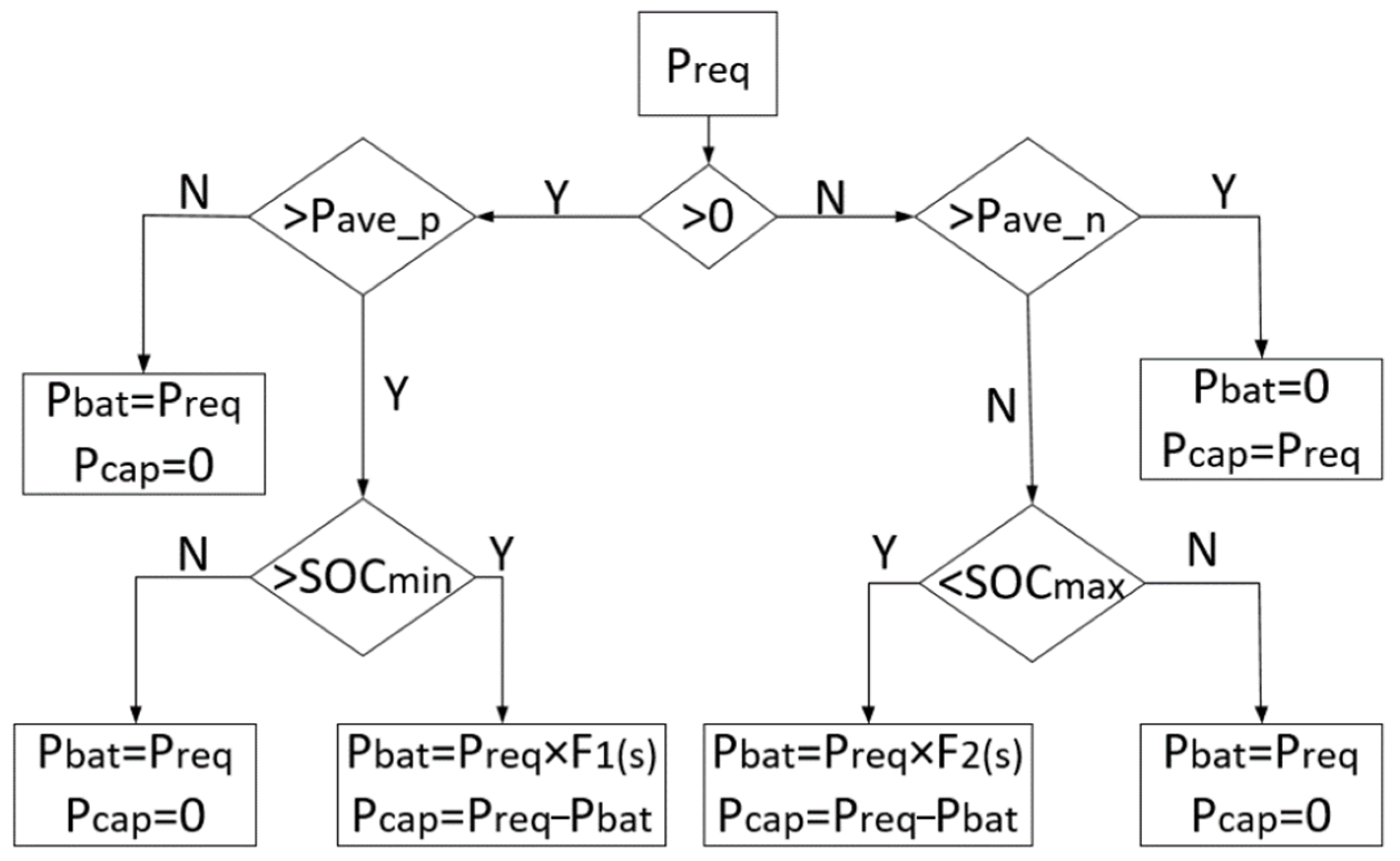
Logic threshold filtering control (LTFC), which is simple to control and highly effective, has been widely applied in the field of automotive control [21,22]. This paper uses the LTFC strategy as a benchmark to study the PSO-FLC energy management method for hybrid energy EVs. The basic process is shown in Figure 7.
Figure 7.
Basic flow of LTFC strategy.
In the figure, denotes demand power; represents battery power; indicates supercapacitor power, is the demand power threshold in drive mode, which is 8.141 kW; is the demand power threshold in brake mode, which is −3.141 kW; and represent the upper and lower limits of the supercapacitor SOC, set at 1 and 0.2 respectively; and denote the filtering functions during driving and braking phases.
4.2. Design of FLC Strategy for “Drive–Brake” Global Power Distribution Under SBFDS
The operating modes of EVs can be roughly divided into driving and braking. Therefore, we divided the FLC strategy into two parts: driving and braking.
- (1)
- Determination of input and output quantities
Based on the energy demand and allocation relationship of the HESS, and neglecting losses during energy transfer between components, the relationship between the power supplied by the power battery and supercapacitor and the required power should satisfy the following equations:
where is the supercapacitor distribution factor; is the power battery allocation factor; is the required power of the EV; and denote the power provided by the battery and the supercapacitor.
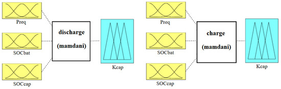
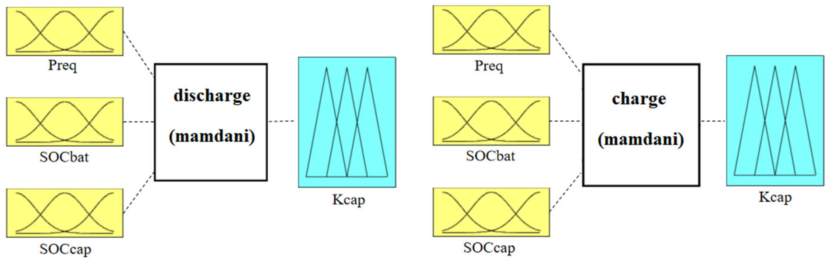
In drive mode, the designed inputs are the EV’s demand power and the SOC values of the supercapacitor and the battery. Through fuzzy logic controller calculations, the output is the supercapacitor allocation factor . In braking mode, the regenerative braking force allocation coefficient is first determined based on the SBFDS. Subsequently, the recoverable braking power is calculated. Finally, using the recoverable power and the SOC values of the supercapacitor and power battery as inputs, the fuzzy logic controller calculates the output: the supercapacitor allocation factor . The basic structure of the fuzzy logic controller in both modes is shown in Figure 8.
Figure 8.
Structure of fuzzy logic controller in drive and brake modes.
- (2)
- Determination of fuzzy set domains, quantification factor and proportional factor
Excessively high or low SOC values can damage the internal structure of energy storage components. To ensure the power battery and supercapacitor operate within safe and efficient ranges, their respective SOC values are controlled within upper and lower limits. The actual domain of demand power does not perfectly correspond to the fuzzy domain. In drive mode, its actual domain should be [0, ], where represents the maximum positive demand power of the electric vehicle under a specific operating condition. Here, the proportional factor is introduced for conversion, defined as = . In brake mode, the actual domain of demand power is [], where represents the maximum braking power of the EV under a given operating condition. A conversion factor is introduced to convert it, that is, = . Consequently, the domain of demand power is [0, 1]. Table 3 presents the fuzzy domains for the inputs and outputs of the fuzzy logic controller in the HESS.
Table 3.
Fuzzy domains of inputs and outputs for the fuzzy logic controller.
- (3)
- Determination of membership functions
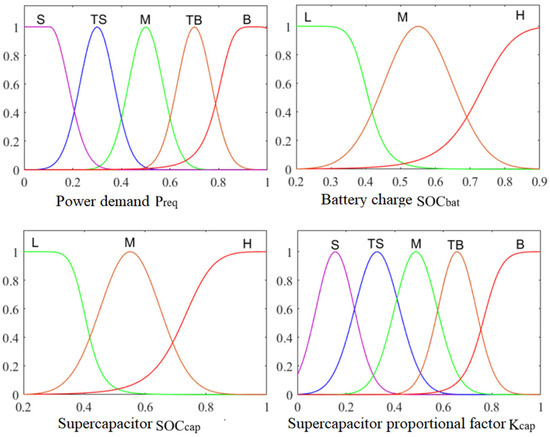
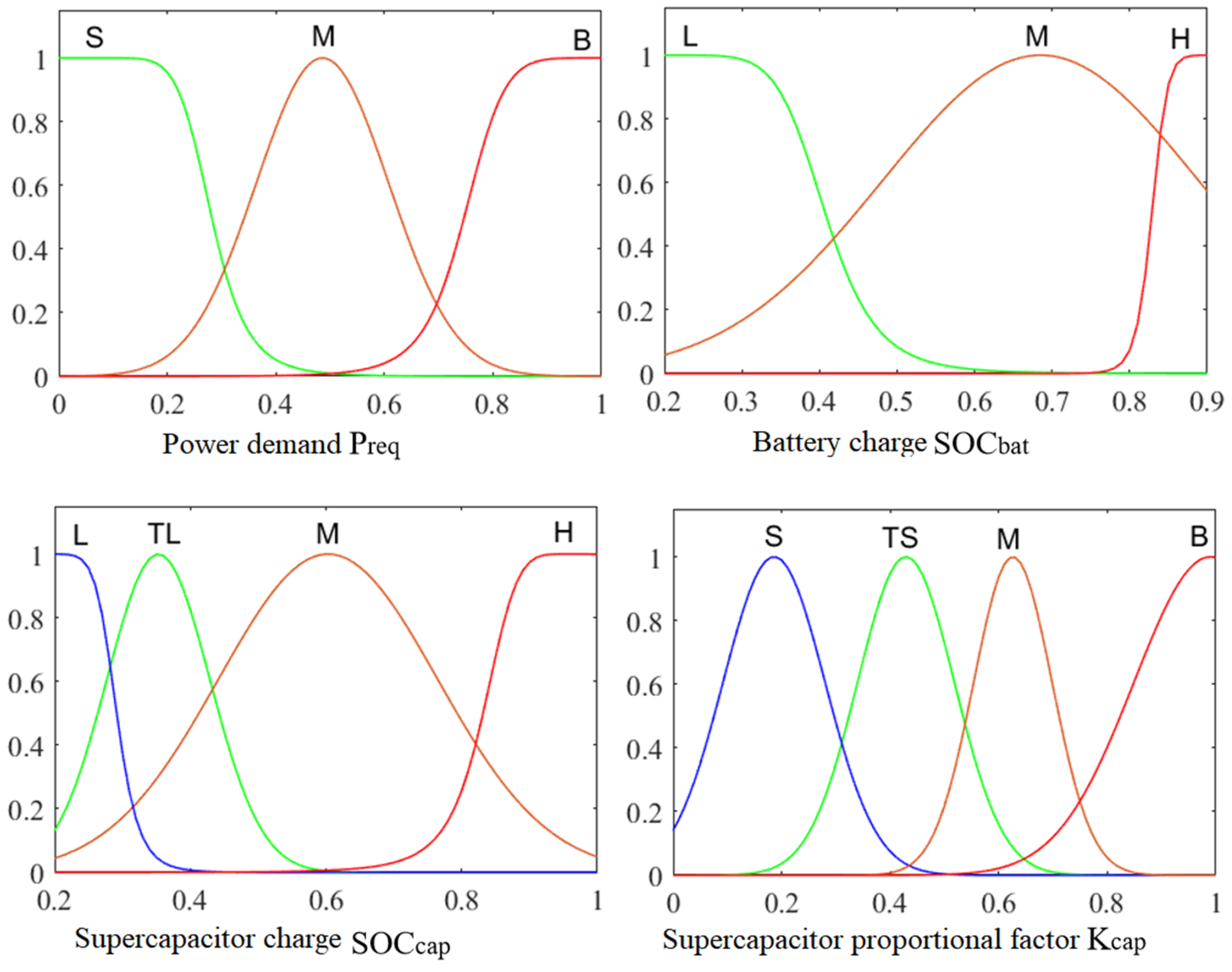
The membership function in a fuzzy logic controller defines the degree of membership for mapping points in the domain to [0, 1]. Typically selected and determined based on human experience, it inherently carries subjectivity and should be refined through practical application. Table 4 presents the linguistic values for each input and output variable in the fuzzy controller described herein.
Table 4.
Language value of input and output.
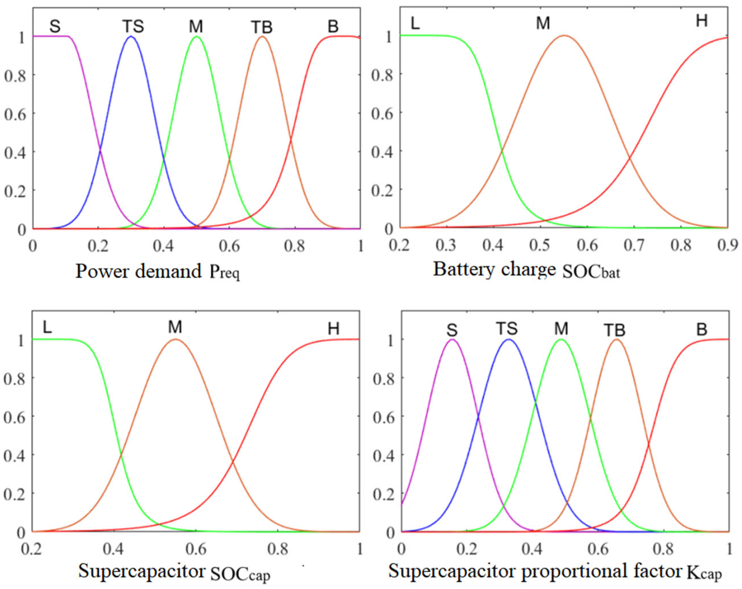
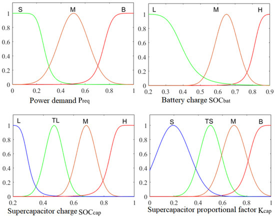
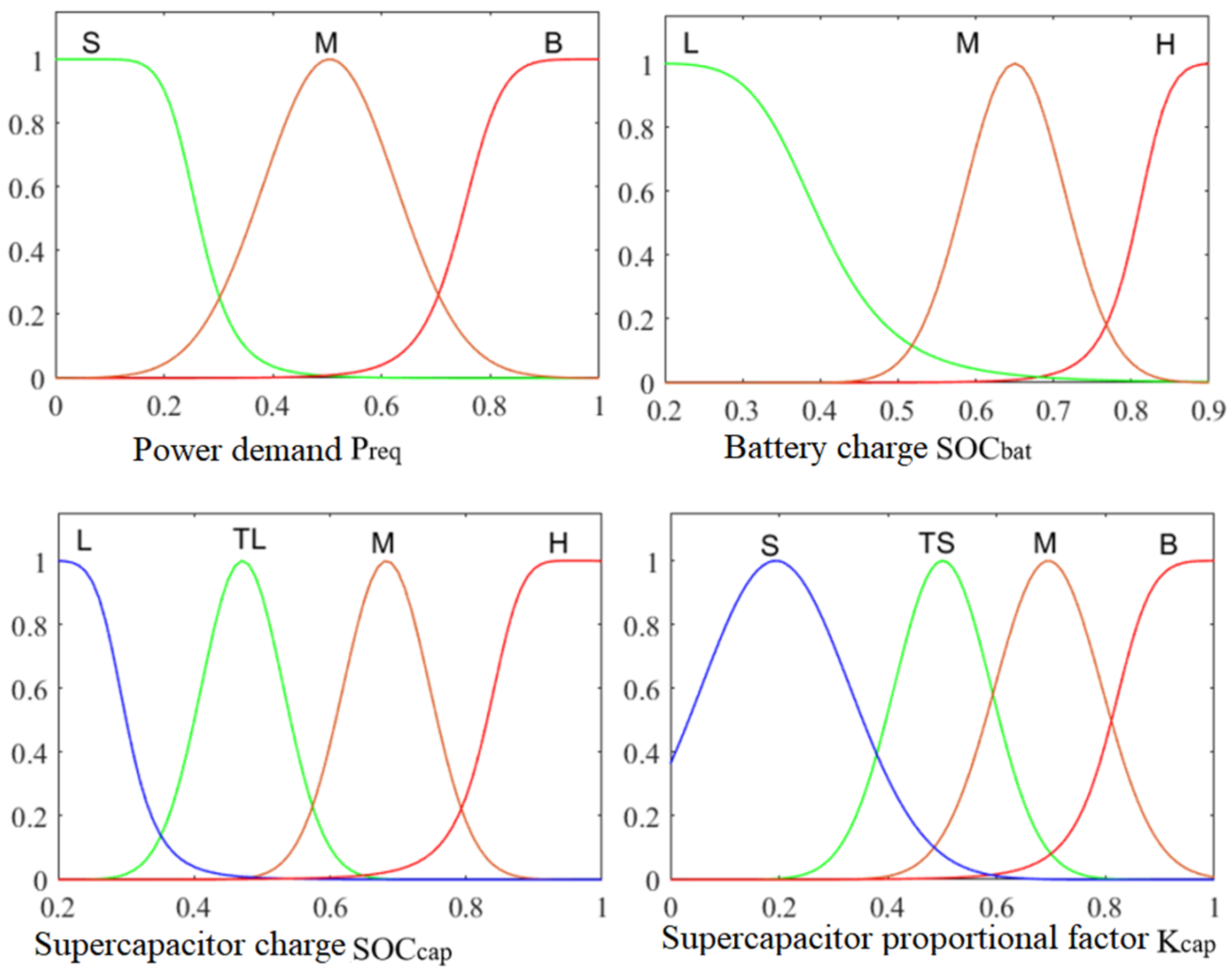
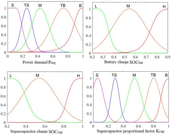
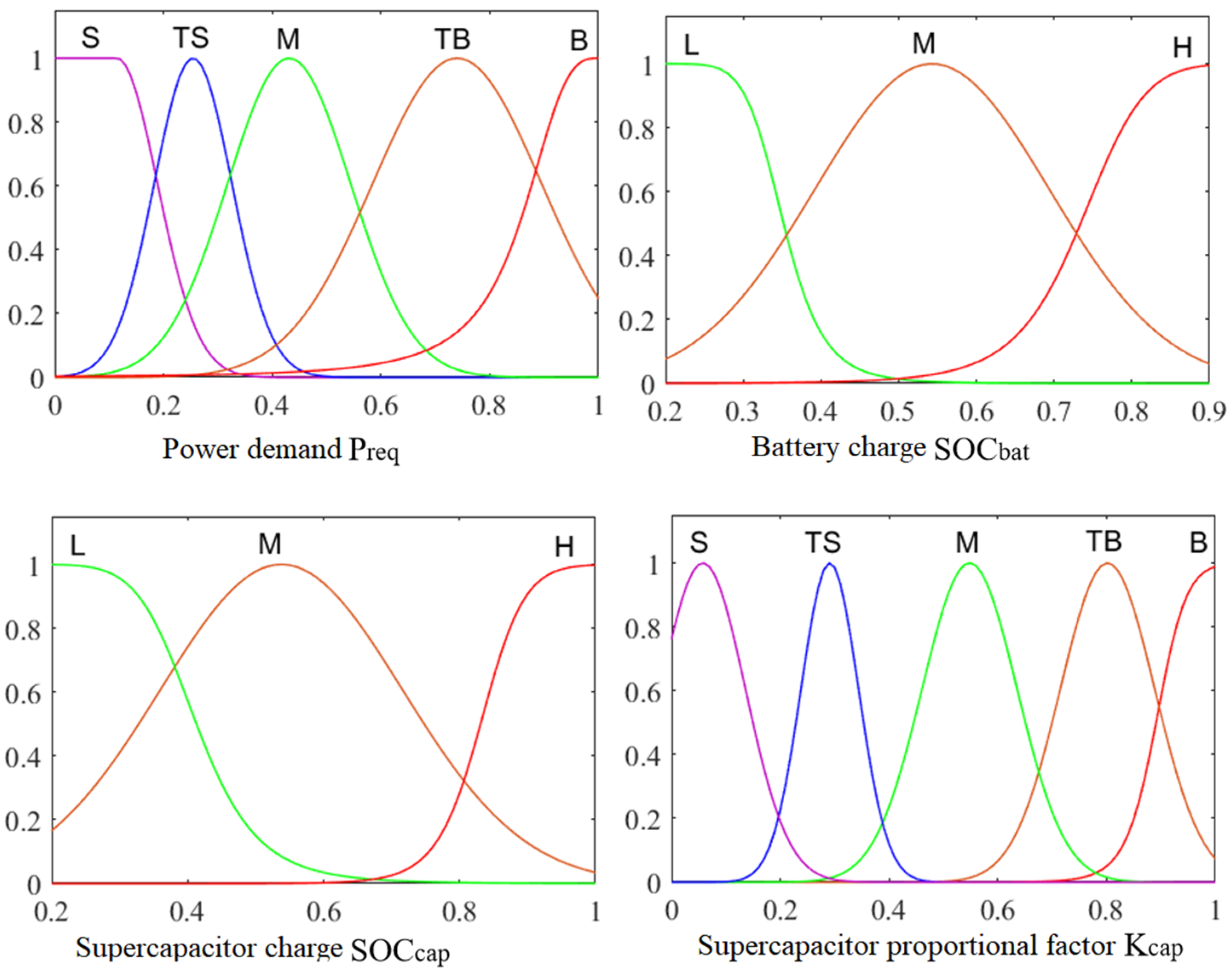
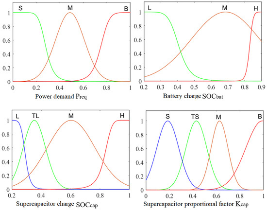
Based on the domains and language values of the input and output variables, the membership functions for the fuzzy logic controller are preliminarily determined as shown in Figure 9 and Figure 10.
Figure 9.
Membership function of fuzzy controller when driving.
Figure 10.
Membership function of fuzzy controller when braking.
- (4)
- Fuzzy rule determination
The core of fuzzy logic controllers lies in fuzzy reasoning. Fuzzy reasoning requires designing FLC rules based on variable language values, membership functions, system characteristics, and domain expertise. Such rules are typically expressed in IF–AND–THEN format. When designing fuzzy logic control rules for the HESS in this study, the following aspects were considered:
- When the power demand : When the vehicle is traveling at a constant speed, the power demand is relatively low, allowing the power battery alone to supply energy and leverage its high energy density advantage. During short bursts of acceleration or light-load starts, if the supercapacitor has sufficient capacity, it can initially provide power to the load. After releasing part of its energy, the freed-up capacity can be reserved for recovering braking energy during deceleration. During prolonged acceleration or full-load starts, excessive current can severely degrade the battery pack’s lifespan while reducing its discharge efficiency. Therefore, the supercapacitor and battery pack must work together to drive the motor, ensuring the battery pack remains healthier and more efficient.
- When the power demand : Supercapacitors primarily engage in energy recovery. This approach enhances overall system energy recovery efficiency while reducing the frequency of energy recovery by the power battery. Once the SOC value of the supercapacitors reaches saturation and can no longer recover braking energy, the power battery takes over to recover the remaining braking energy.
Based on the aforementioned factors and referring to expert control experience as well as the characteristics of the hybrid energy system, the formulated fuzzy control rules are presented in Table 5 and Table 6. There are 36 fuzzy rules for the braking mode and 45 fuzzy rules for the driving mode.
Table 5.
Fuzzy rules when braking.
Table 6.
Fuzzy rules when driving.
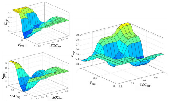
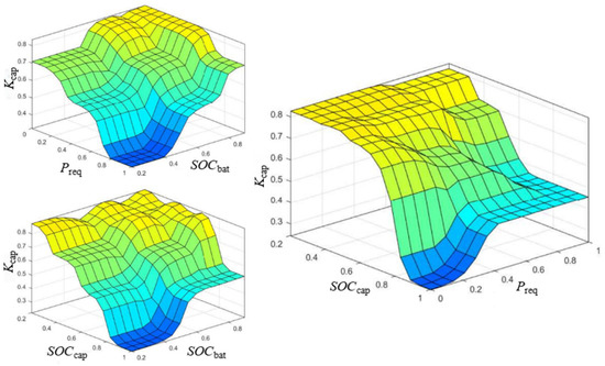
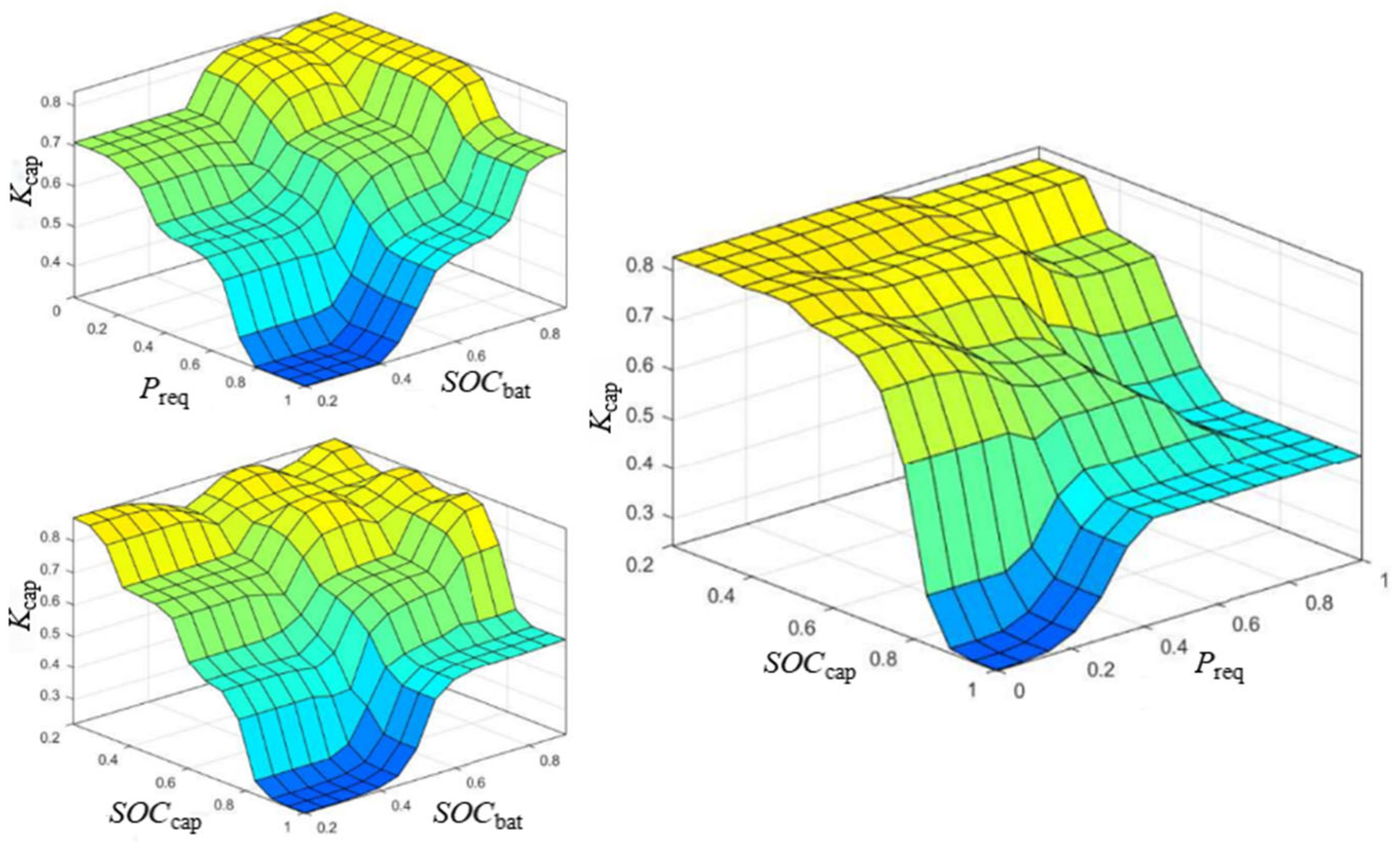
The fuzzy control rules were implemented in the fuzzy controller, yielding the relationship diagrams between input and output variables for the driving and braking modes, as illustrated in Figure 11 and Figure 12, respectively.
Figure 11.
Relation between input and output when driving.
Figure 12.
Relation between input and output when braking.
4.3. PSO-FLC Energy Control Strategy
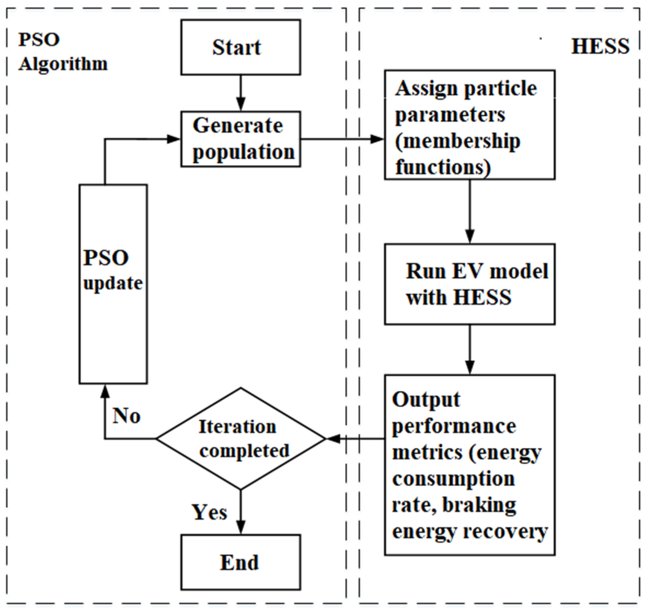
The optimization of the hybrid energy management system for electric vehicles is characterized by multiple parameters, multiple objectives, and strong coupling. The particle swarm optimization (PSO) algorithm, a stochastic optimization method based on swarm intelligence, exhibits strong robustness, powerful global optimization capability, adaptability to dynamic optimization, high efficiency, and fast convergence [23,24]. In this study, with the dual objectives of maximizing braking energy recovery efficiency and minimizing energy consumption per 100 km, the PSO algorithm is employed to optimize the parameters of the membership functions in the fuzzy logic controller.
- (1)
- Optimization Model of HESS
The objective of energy management for the HESS is to enhance vehicle economic performance by adjusting the power distribution factors between the power battery and supercapacitor while ensuring normal operation of the hybrid EV. Here, vehicle economic performance primarily refers to two aspects: energy consumption rate (ECR) and braking energy recovery efficiency (BERE). ECR is a crucial metric for evaluating electric vehicle economic performance, defined as the ratio of energy consumed during vehicle operation to the distance traveled. Its calculation formula is as follows:
where C is the ECR, Wh/km; E is the energy consumed by the vehicle, Wh; and D is the distance traveled, km.
The braking energy recovery efficiency is defined as the ratio of the energy recovered by the system to the braking energy generated when the vehicle decelerates or brakes. It can be expressed as
where is the energy recovered by the system, J; is the braking energy generated during vehicle braking or deceleration, J.
The objective function for optimizing the HESS can be expressed as
where and are the weights of the two parts, with 1. A smaller objective function value indicates better economic performance of the hybrid EV, bringing it closer to the optimal solution.
Based on the above optimization objective function and the characteristics of the HESS, the following optimization model is established:
where and denote the minimum and maximum power capacities of the supercapacitor, respectively, and denote the minimum and maximum power capacities of the power battery, respectively, is the power supplied by the HESS, denotes the vehicle’s power demand, is the driving time of the vehicle, and = 0.5.
- (2)
- Solution of the optimization model
For both driving and braking conditions, Gaussian and S-type membership functions were selected for the fuzzy logic controller. The expressions for these two membership functions are shown in Equation (32).
It can be observed that the characteristics of both membership function types are determined by and . Therefore, it is only necessary to adjust the values of the and , which can change the output of the membership function and finally achieve the optimization objective.
Taking the objective function as the fitness function J, its expression is
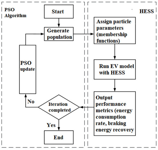
The PSO algorithm program was developed in an m file within Matlab 9.12. In the program, the full vehicle model is invoked, and a fuzzy logic controller is created with the corresponding parameters integrated. Simultaneously, the hybrid energy system supplies real-time data required for calculating the fitness value to the PSO algorithm program. The flowchart of this process is illustrated in the Figure 13.
Figure 13.
Flow chart of optimization model solution.
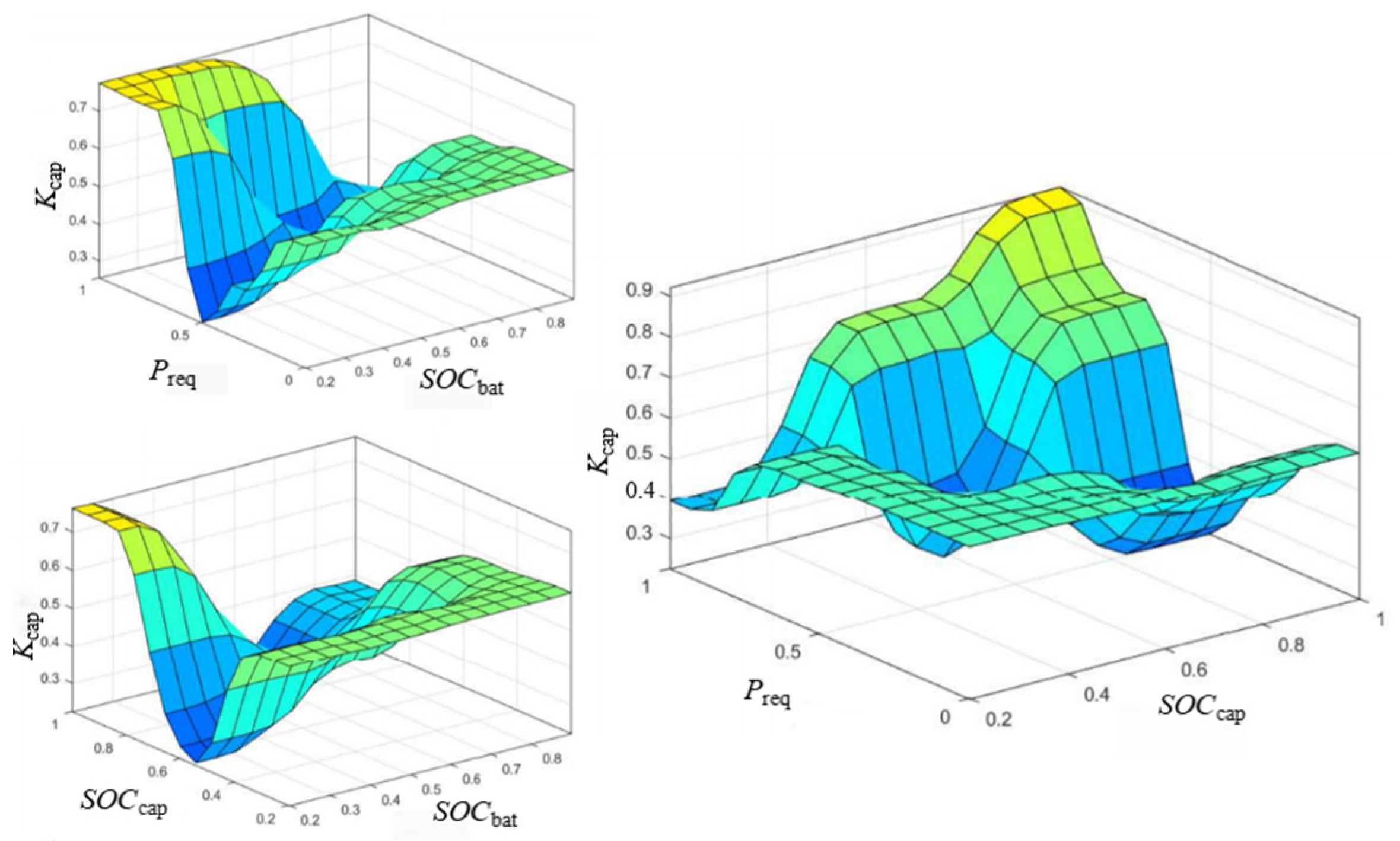
The membership function diagrams of the fuzzy logic controller for both driving and braking states, optimized by the particle swarm optimization algorithm, are shown in the Figure 14 and Figure 15.
Figure 14.
Optimized membership function of FLC when driving.
Figure 15.
Optimized membership function of FLC when braking.
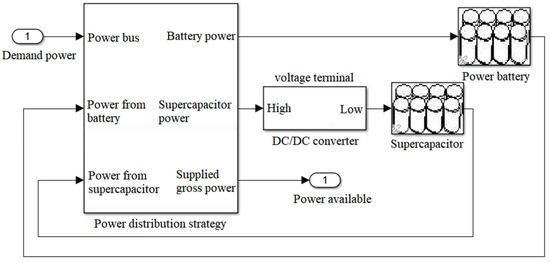
The established control strategy is encapsulated with models of the power battery, supercapacitor, and bidirectional DC/DC converter to form the top-level model of the hybrid energy system, whose structure is shown in Figure 16.
Figure 16.
Top-level model of HESS.
4.4. Optimization Results and Comparative Analysis
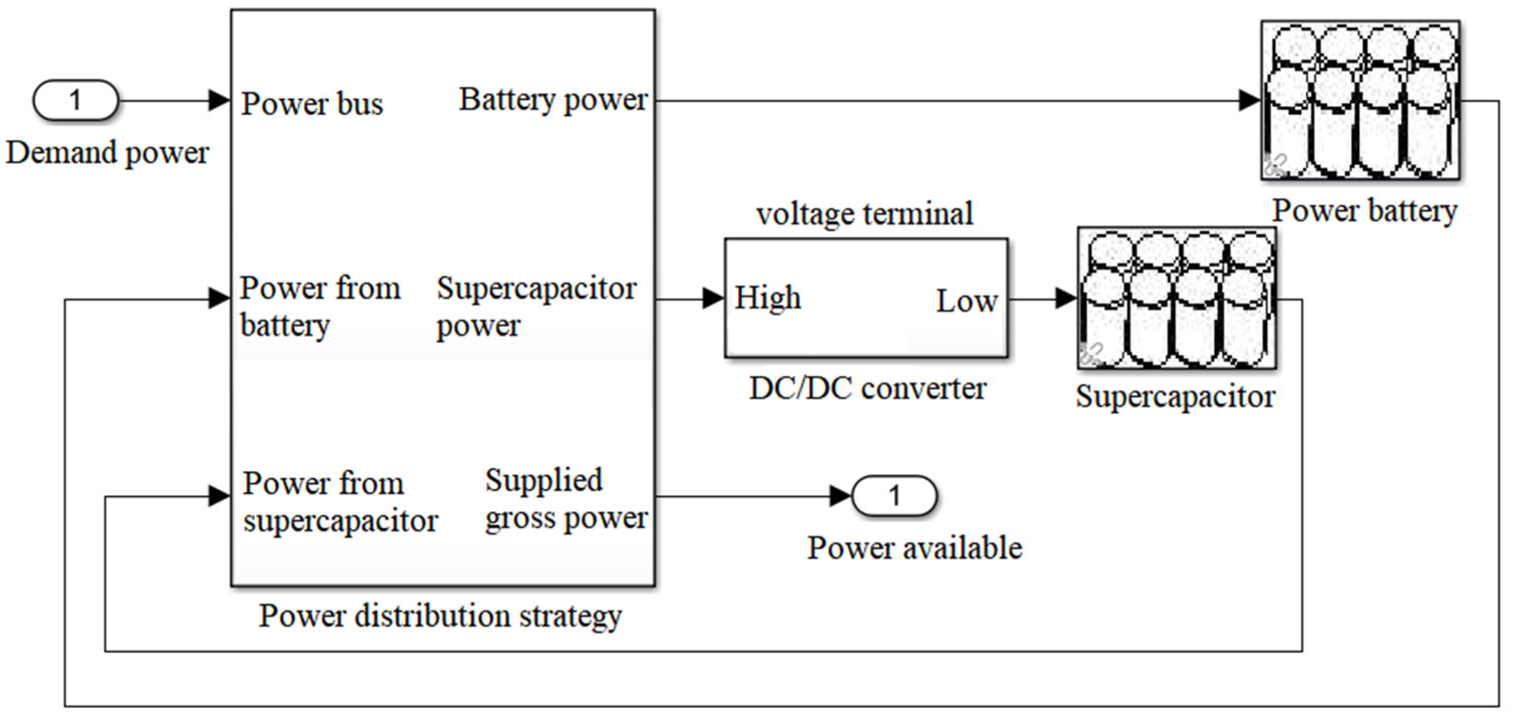
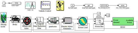
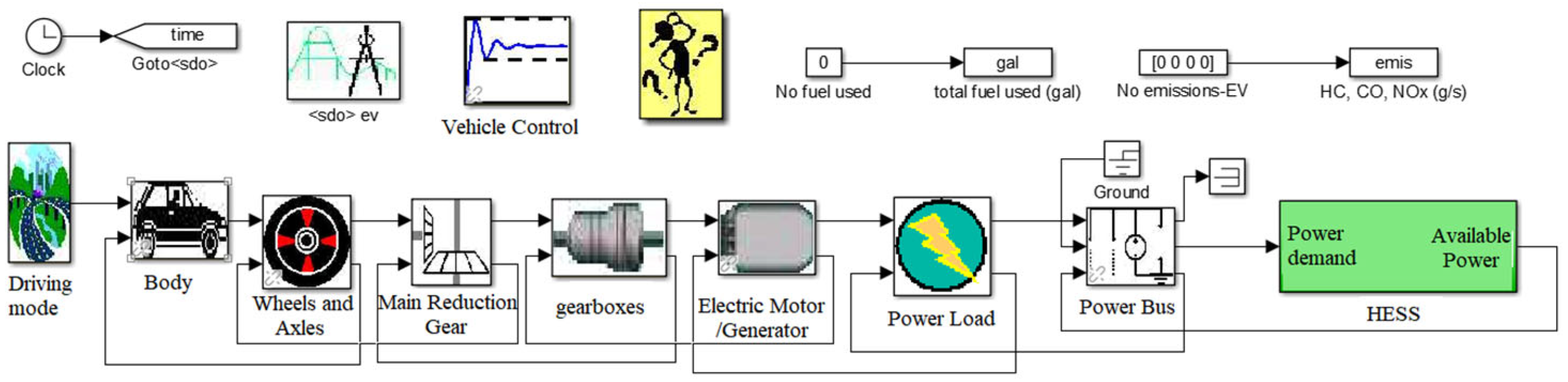
A simulation model of a hybrid energy electric vehicle was constructed in ADVISOR. The model primarily consists of modules such as the vehicle body, transmission, motor/generator, power bus, and hybrid energy system. The structure of the developed model is illustrated in Figure 17.
Figure 17.
Top model.
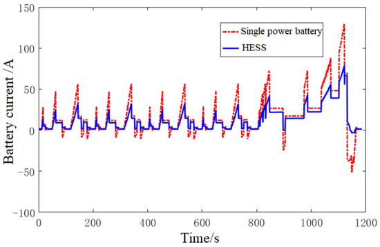
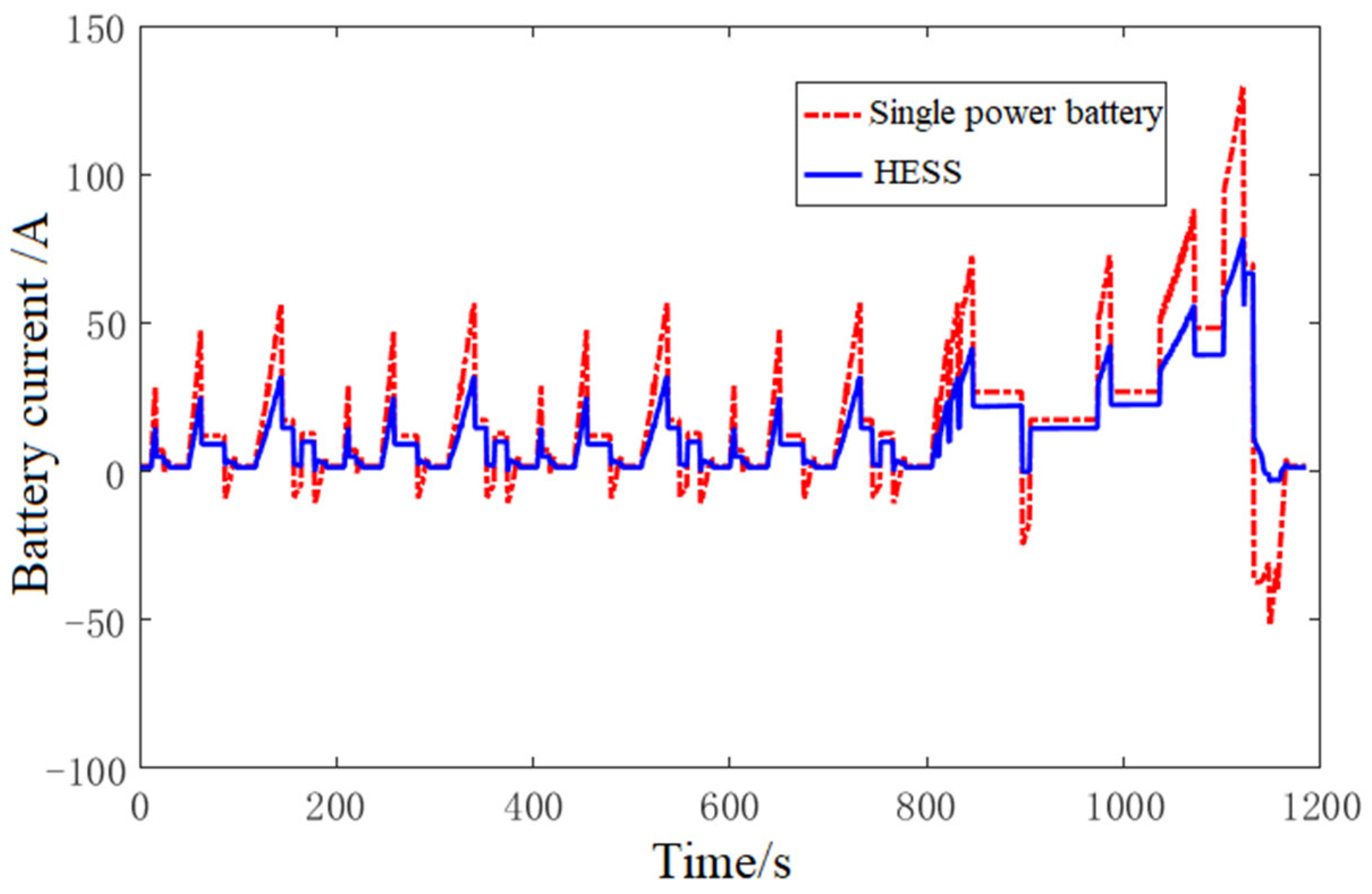
Simulations were conducted for both a single traction battery electric vehicle and a hybrid energy system electric vehicle under the NEDC driving cycle. The variation in the traction battery current during vehicle operation is shown in Figure 18, where positive values indicate energy discharge during driving and negative values represent energy recovery during braking. It can be observed that the traction battery current in the electric vehicle equipped with a hybrid energy system is significantly lower than that in the vehicle with a single traction battery system. Moreover, in the hybrid energy system, the traction battery current rarely drops below zero. The primary reasons are as follows: During driving, both the supercapacitor and the traction battery release energy in the hybrid energy system, resulting in a lower traction battery current compared to the single traction battery system. During braking, the hybrid energy system primarily relies on the supercapacitor to recover energy. The traction battery only engages in energy recovery when the supercapacitor’s state of charge (SOC) reaches its upper limit and can no longer absorb additional energy. Hence, the traction battery current in the hybrid energy system seldom falls below zero. This further illustrates the “peak shaving and valley filling” function of the supercapacitor in the hybrid energy system, which protects the traction battery from high-current impacts and extends its service life.
Figure 18.
Comparison of battery current between pure battery system and hybrid energy storage system.
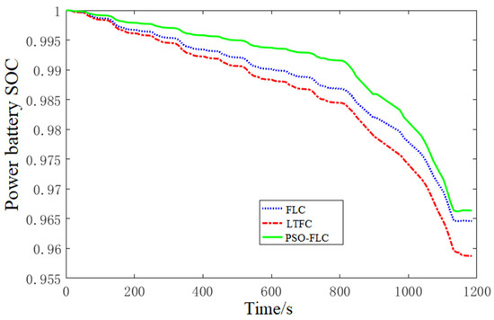
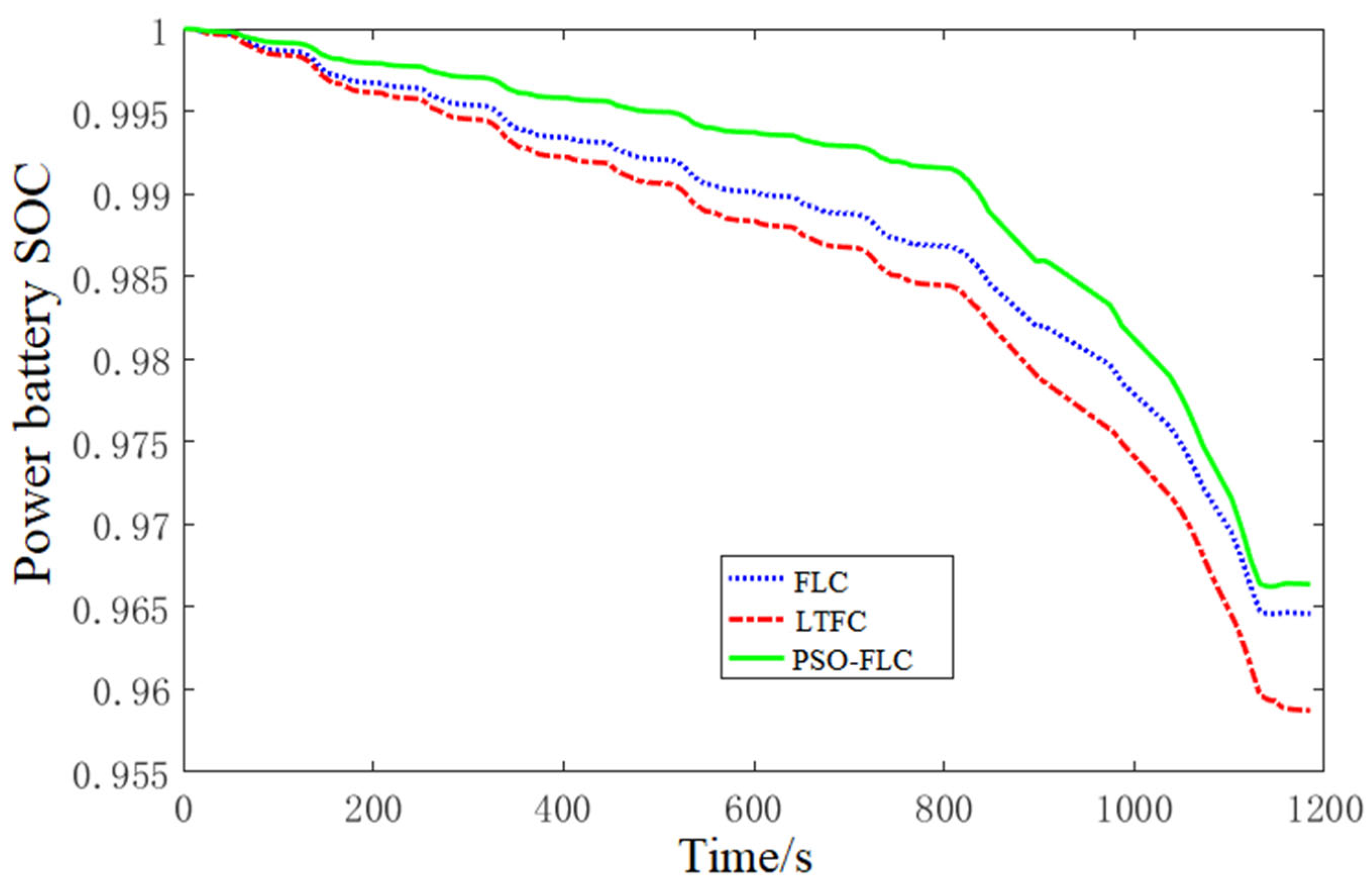
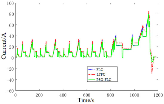
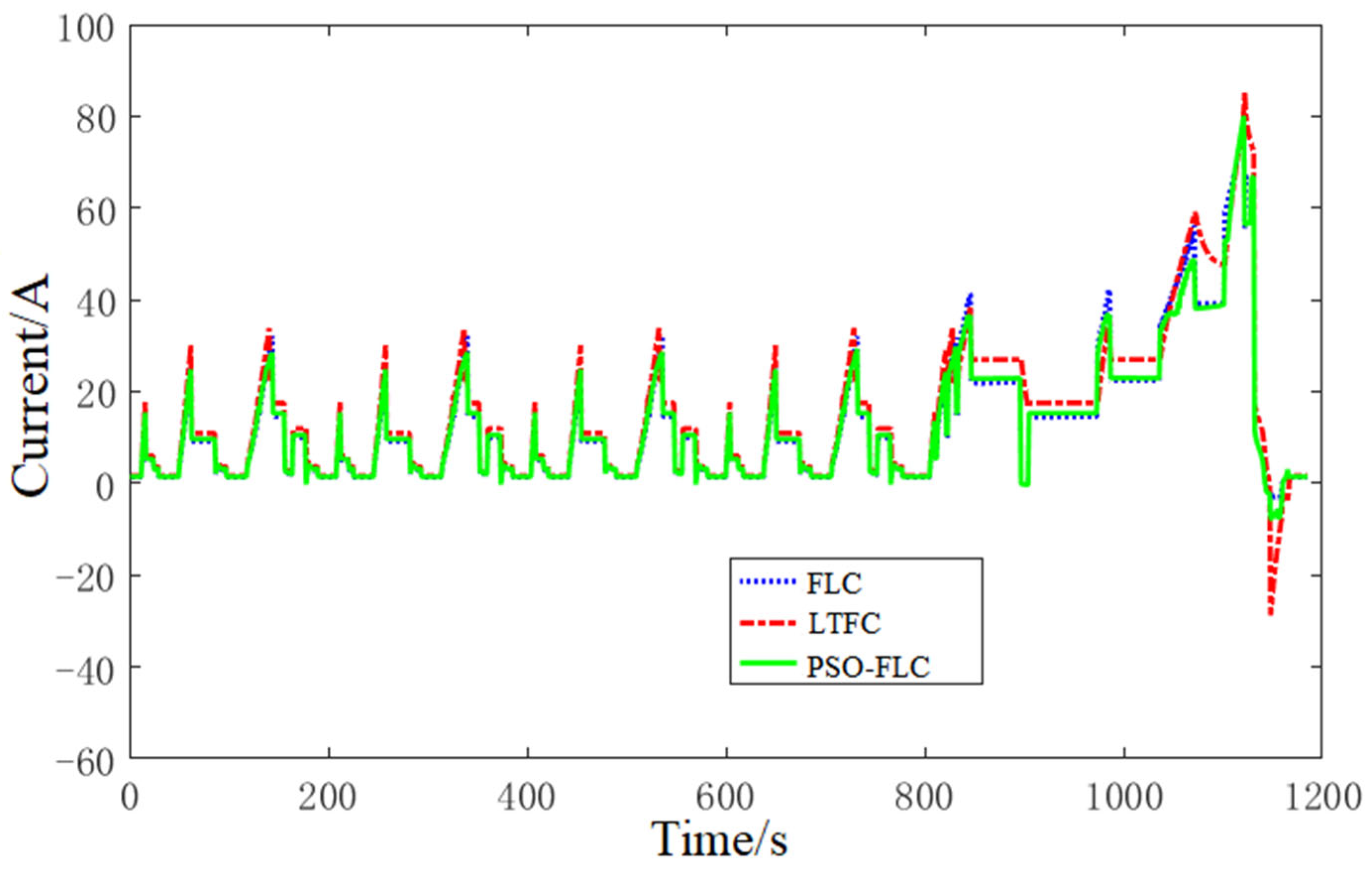
The optimized FLC strategy, the unoptimized FLC strategy, and the LTFC strategy based on a filtering concept were applied to the hybrid energy electric vehicle model for simulation. Figure 19 and Figure 20 present the simulation results under the NEDC driving cycle.
Figure 19.
Comparison of battery SOC under different control strategies.
Figure 20.
Comparison of battery current under different control strategies.
As shown in Figure 19, after one NEDC cycle simulation, the power battery SOC under the PSO-FLC strategy ultimately stabilized at 96.68%. Compared to the unoptimized FLC and LTFC strategies, the optimized FLC strategy achieved energy savings of 0.22% and 0.81% for the power battery, respectively. Comparing the three battery SOC change curves reveals that, while the unoptimized FLC outperforms the LTFC, its SOC decline accelerates significantly at medium-to-high speeds, exposing the rule base’s limited adaptability to complex conditions. The particle swarm algorithm optimized FLC strategy maintains the highest SOC level throughout the entire NEDC cycle, further enhancing the EV’s driving range.
As shown in Figure 20, after undergoing one NEDC cycle simulation, the FLC strategy optimized by the particle swarm algorithm increases the involvement of the supercapacitor in the HESS. This reduces the peak current of the power battery by approximately 6.4%, mitigating the impact of high currents on the power battery. This more fully demonstrates the supercapacitor’s role in “shaving peaks and filling valleys”, enhancing the smoothness and adaptability of the system response.
Table 7 presents the comparison of regenerative braking energy recovery and economic performance among three control strategies for electric vehicles under NEDC conditions. These data indicate that, compared to the unoptimized FLC, the optimized FLC strategy improves braking energy recovery efficiency by 5.45%, reduces NEDC energy consumption by 216 kJ, and decreases energy consumption per 100 km by 0.54 kWh. Compared to the LTFC, the optimized FLC strategy enhances braking energy recovery efficiency by 10.32%, reduces NEDC energy consumption by 381 kJ, and decreases electricity consumption per 100 km by 0.96 kWh, demonstrating more pronounced improvements.
Table 7.
Simulation results of energy recovery and consumption under different control strategies.
5. Conclusions
This paper addresses energy management in hybrid EVs by integrating a safety-efficiency-coordinated SBFDS with a PSO-FLC algorithm. It constructs and validates a dynamic power allocation strategy for the entire “drive–brake” process in hybrid EVs. Key conclusions are as follows:
- (1)
- Bench tests indicate a proportional relationship between the supercapacitor power allocation factor and the system’s energy recovery efficiency. To enhance the energy recovery efficiency of the hybrid energy system, priority should be given to utilizing the supercapacitor for energy recovery during operation whenever possible.
- (2)
- Based on the I-curve, ECE regulation curve, and f-curve, an SBFDS is designed to maximize energy recovery while ensuring braking safety. By dynamically adjusting the braking force distribution ratio between the front and rear axles, a balance between braking safety and energy efficiency is achieved.
- (3)
- The PSO algorithm is employed to optimize the FLC, enabling globally optimal power allocation under both driving and braking conditions. Compared to the LTFC strategy, the optimized FLC strategy improves braking energy recovery efficiency by 10.32%, reduces energy consumption per 100 km by 0.96 kWh, and decreases the peak current by approximately 6.4% under the NEDC cycle. This effectively enhances vehicle economy and extends battery lifespan.
The FLC adopted in this study primarily constructs its rule base based on expert experience. Although its membership function parameters have been finely tuned using the PSO algorithm, demonstrating good control performance under known or common operating conditions, it inherently lacks adaptive and evolutionary capabilities for unknown scenarios. When encountering untrained driving situations, it may fail to make optimal decisions, leading to degraded control performance or even undesired responses. Therefore, future research could explore intelligent fuzzy systems with self-learning and adaptive capabilities. For instance, the adaptive neuro-fuzzy inference system [25] or reinforcement learning frameworks [26] could be introduced to enable the system to dynamically evolve through continuous interaction with the environment.
Author Contributions
Conceptualization, Z.H.; software, C.W.; writing—original draft preparation, N.L.; writing—review and editing, X.N. All authors have read and agreed to the published version of the manuscript.
Funding
This research was funded by general scientific research projects of the Zhejiang Provincial Department of Education, grant number Y202352247.
Data Availability Statement
The data that support the findings of this study are available from the corresponding author upon reasonable request.
Conflicts of Interest
ChaoPeng Wang is an employee of Zhejiang Sanhua Automotive Components Co., Ltd. The remaining authors declare that the research was conducted in the absence of any commercial or financial relationships that could be construed as a potential conflict of interest.
Abbreviations
| EV | Electric vehicle |
| HESS | Hybrid energy storage system |
| PSO | Particle swarm optimization |
| FLC | Fuzzy logic control |
| SBFDS | Segmented braking force distribution strategy |
| SOC | State of charge |
| LTFC | Logic threshold filtering control |
References
- Hossain, M.N.; Hasan, M.M.; Habib, M.A.; Bin Ferdous, F.; Rahman, S. Assessing economic viability and environmental impact of solar-powered EV charging station in Gazipur, Bangladesh: A case study. Sol. Compass 2024, 12, 100091. [Google Scholar] [CrossRef] [Scilit]
- Saklani, M.; Saini, D.K.; Yadav, M.; Gupta, Y.C. Navigating the Challenges of EV Integration and Demand-Side Management for India’s Sustainable EV Growth. IEEE Access 2024, 12, 143767–143796. [Google Scholar] [CrossRef] [Scilit]
- Tawfik, M.I.; Ali, A.; Asfoor, M. A combined trade-off strategy of battery degradation, charge retention, and driveability for electric vehicles. Sci. Rep. 2024, 14, 21995. [Google Scholar] [CrossRef] [Scilit]
- Saxena, S.; Le Floch, C.; MacDonald, J.; Moura, S. Quantifying EV battery end-of-life through analysis of travel needs with vehicle powertrain models. J. Power Sources 2015, 282, 265–276. [Google Scholar] [CrossRef] [Scilit]
- Zhang, C.; Min, H.T.; Yu, Y.B.; Wang, D.; Luke, J.; Opila, D.; Saxena, S. Using CPE Function to Size Capacitor Storage for Electric Vehicles and Quantifying Battery Degradation during Different Driving Cycles. Energies 2016, 9, 903. [Google Scholar] [CrossRef] [Scilit]
- Habib, A.K.M.A.; Hasan, M.K.; Issa, G.F.; Singh, D.; Islam, S.; Ghazal, T.M. Lithium-Ion Battery Management System for Electric Vehicles: Constraints, Challenges, and Recommendations. Batteries 2023, 9, 152. [Google Scholar] [CrossRef] [Scilit]
- Lu, Q.; Zhou, W.L.; Zheng, Y.P. Regenerative Braking Control Strategy with Real-Time Wavelet Transform for Composite Energy Buses. Machines 2022, 10, 673. [Google Scholar] [CrossRef] [Scilit]
- Yuan, X.H.; Yan, G.D.; Li, H.T.; Liu, X.; Su, C.-Q.; Wang, Y.-P. Research on energy management strategy of fuel cell–battery–supercapacitor passenger vehicle. Energy Rep. 2022, 8, 1339–1349. [Google Scholar] [CrossRef] [Scilit]
- Hasrour, A.; Harrouf, M.; Betk, A.; Abdeddaim, S.; Tiar, M. Adaptive wavelet-fuzzy energy management system for battery-supercapacitor energy storage system in electric vehicles integrating driving pattern recognition. J. Energy Storage 2025, 129, 117330. [Google Scholar] [CrossRef] [Scilit]
- Techalimsakul, P.; Sawetmethikul, P. Efficiency Analysis of Hybrid Extreme Regenerative with Supercapacitor Battery and Harvesting Vibration Absorber System for Electric Vehicles Driven by Permanent Magnet Synchronous Motor 30 kW. World Electr. Veh. J. 2024, 15, 214. [Google Scholar] [CrossRef] [Scilit]
- Wai, C.K.; Sadeq, T.; Hau, L.C. Advanced Adaptive Rule-Based Energy Management for Hybrid Energy Storage Systems (HESSs) to Enhance the Driving Range of Electric Vehicles. Vehicles 2025, 7, 6. [Google Scholar] [CrossRef] [Scilit]
- Sadeq, T.; Wai, C.K.; Morris, E.; Tarboosh, Q.A.; Aydogdu, O. Optimal Control Strategy to Maximize the Performance of Hybrid Energy Storage System for Electric Vehicle Considering Topography Information. IEEE Access 2020, 8, 216994–217007. [Google Scholar] [CrossRef] [Scilit]
- Deptula, A.; Augustynowicz, A.; Stosiak, M.; Towarnicki, K.; Karpenko, M. The Concept of Using an Expert System and Multi-Valued Logic Trees to Assess the Energy Consumption of an Electric Car in Selected Driving Cycles. Energies 2022, 15, 4631. [Google Scholar] [CrossRef] [Scilit]
- Hu, J.; Liu, D.; Du, C.Q.; Yan, F.; Lv, C. Intelligent energy management strategy of hybrid energy storage system for electric vehicle based on driving pattern recognition. Energy 2020, 198, 117298. [Google Scholar] [CrossRef] [Scilit]
- Selvakumar, R.B.; Vivekanandan, C.; Sharma, H.; Vekariya, V.; Varma, R.A.; Mohanavel, V.; Ramkumar, G.; Kumar, A.S.M.; Abdullah-Al-Wadud, M. Energy management of a dual battery energy storage system for electric vehicular application. Comput. Electr. Eng. 2024, 115, 109099. [Google Scholar] [CrossRef] [Scilit]
- Yangbo, Y. Research on Design and Power Allocation Strategy of Composite Power System for Electric Vehicles. Master’s Thesis, Jiangsu University, Zhenjiang, China, 2018. [Google Scholar]
- Rezk, H.; Ghoniem, R.M. Optimal Load Sharing between Lithium-Ion Battery and Supercapacitor for Electric Vehicle Applications. World Electr. Veh. J. 2023, 14, 201. [Google Scholar] [CrossRef] [Scilit]
- Li, S.Q.; Yu, B.; Feng, X.Y. Research on braking energy recovery strategy of electric vehicle based on ECE regulation and I curve. Sci. Prog. 2020, 103, 36850419877762. [Google Scholar] [CrossRef] [Scilit]
- Zhang, Z.J.; Dong, Y.Y.; Han, Y.W. Dynamic and Control of Electric Vehicle in Regenerative Braking for Driving Safety and Energy Conservation. J. Vib. Eng. Technol. 2020, 8, 179–197. [Google Scholar] [CrossRef] [Scilit]
- Yin, Z.J.; Ma, X.G.; Zhang, C.Y.; Su, R.; Wang, Q. A Logic Threshold Control Strategy to Improve the Regenerative Braking Energy Recovery of Electric Vehicles. Sustainability 2023, 15, 16850. [Google Scholar] [CrossRef] [Scilit]
- Du, W.; Zhao, S.D.; Jin, L.Y.; Gao, J.; Li, H. Parameter optimization of rule-based control strategy for multi-mode hybrid electric vehicle. Proc. Inst. Mech. Eng. Part D—J. Automob. Eng. 2020, 234, 2706–2716. [Google Scholar] [CrossRef] [Scilit]
- Yang, J.; Zhang, T.Z.; Hong, J.C.; Zhang, H.; Zhao, Q.; Meng, Z. Research on driving control strategy and Fuzzy logic optimization of a novel mechatronics-electro-hydraulic power coupling electric vehicle. Energy 2021, 233, 121221. [Google Scholar] [CrossRef] [Scilit]
- Tu, J.; Bai, Z.F.; Wu, X.L. Sizing of a Plug-In Hybrid Electric Vehicle with the Hybrid Energy Storage System. World Electr. Veh. J. 2022, 13, 110. [Google Scholar] [CrossRef] [Scilit]
- Ben Halima, N.; Ben Hadj, N.; Ben Halima, N.; Neji, R. Fuel consumption comparative optimization for parallel hybrid electric vehicle based on PSO and DIRECT algorithms. Proc. Inst. Mech. Eng. Part D—J. Automob. Eng. 2025, 239, 2913–2936. [Google Scholar] [CrossRef] [Scilit]
- Kheioon, L.A.; Al-Sabur, R.; Sharkawy, A.-N. Design and Modeling of an Intelligent Robotic Gripper Using a Cam Mechanism with Position and Force Control Using an Adaptive Neuro-Fuzzy Computing Technique. Automation 2025, 6, 4. [Google Scholar] [CrossRef] [Scilit]
- Li, F.; Gao, Y.; Wu, Y.; Xia, Y.; Wang, C.; Hu, J.; Huang, Z. Incentive learning–based energy management for hybrid energy storage system in electric vehicles. Energy Convers. Manag. 2023, 293, 117480. [Google Scholar] [CrossRef] [Scilit]


Disclaimer/Publisher’s Note: The statements, opinions and data contained in all publications are solely those of the individual author(s) and contributor(s) and not of MDPI and/or the editor(s). MDPI and/or the editor(s) disclaim responsibility for any injury to people or property resulting from any ideas, methods, instructions or products referred to in the content. |
© 2026 by the authors. Published by MDPI on behalf of the World Electric Vehicle Association. Licensee MDPI, Basel, Switzerland. This article is an open access article distributed under the terms and conditions of the Creative Commons Attribution (CC BY) license.