Optimal Design of Dual Pantograph Parameters for Electrified Roads
Abstract
1. Introduction
2. Methods
2.1. Catenary Model
2.2. Pantograph Model
- z governs the global vertical separation between the pantograph and the catenary, directly affecting the contact force magnitude.
- α captures left–right asymmetry in dual-head, dual-wire systems, since road-induced roll motions tilt the pantograph base and cause differential displacements at the two contact points.
2.3. Pantograph–Catenary Interaction Solution
- Ff is the pantograph–catenary contact force,
- kc is the stiffness of the penalty spring element, and kc = 50,000 Nm−1,
- z1 is the vertical displacement of the pantograph head,
- zc is the vertical displacement of the contact node on the catenary.
- M, C, and K are the generalized mass, damping, and stiffness matrices of the system,
- , and U are the displacement, velocity, and acceleration matrices,
- F is the generalized external force vector applied to the system.
- Ut and Ut+Δt are the displacement matrices at time t and t + Δt,
- α and β are weighting parameters controlling numerical damping and stability.
3. Experiments and Simulation Results
3.1. Model Validation of the Pantograph–Catenary System
3.2. Pantograph–Catenary Contact Force Under Road Excitation
3.3. Pantograph Parameter Optimization
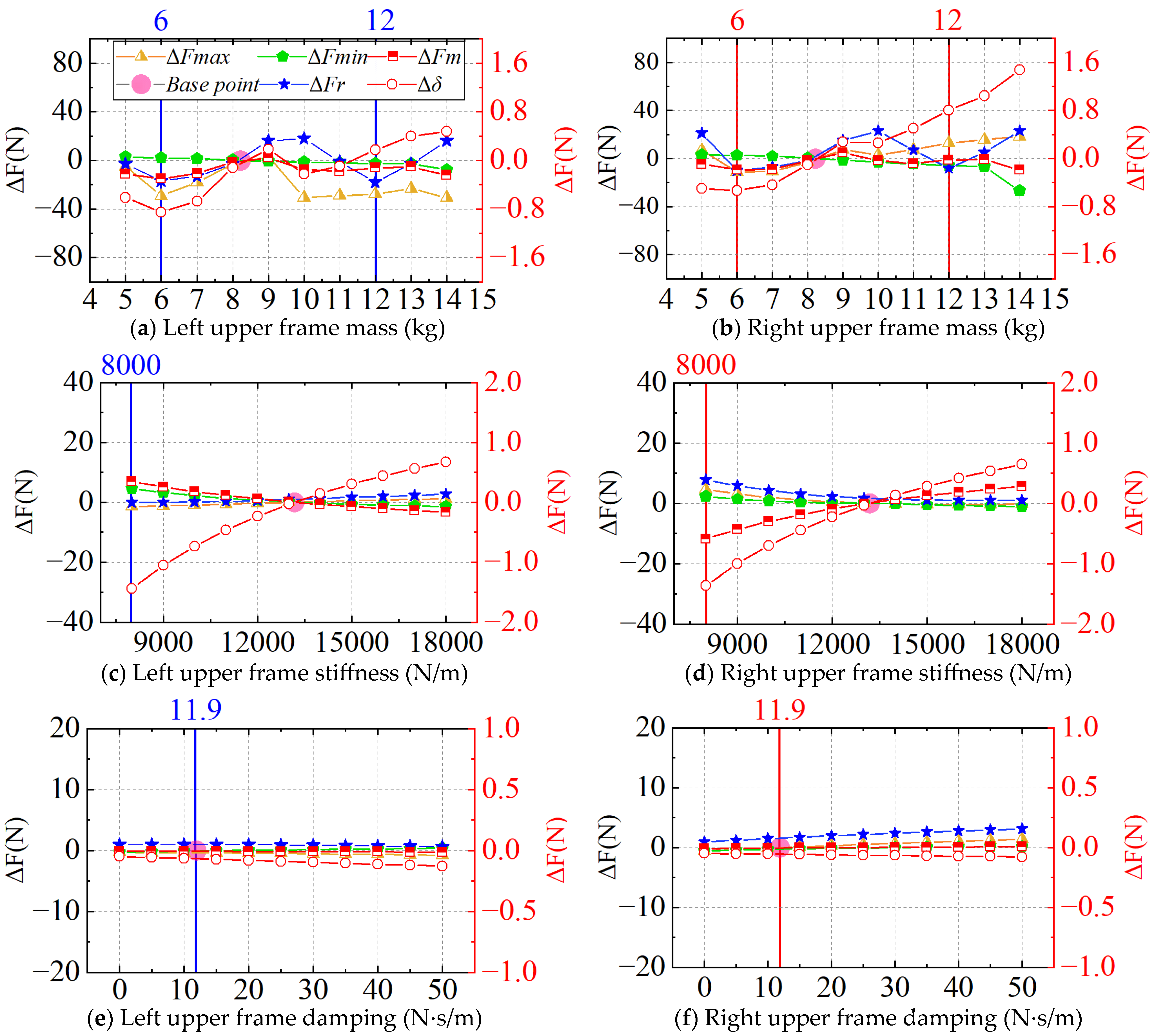
- From the perspective of contact force performance evaluation, the selection of pantograph parameters should aim to: Reduce the maximum contact force Fmax, to avoid hard impacts between the pantograph and catenary, which may cause fatigue damage to the contact wire and abnormal wear of the pantograph strip; Lower the pan-up contact force Fr, in order to minimize transient disturbances to the catenary system during pantograph lifting; Decrease the standard deviation Δδ, to suppress fluctuations in the contact force; Increase the minimum contact force Fmin, to reduce the risk of loss of contact (dewirements) and ensure continuous current collection.
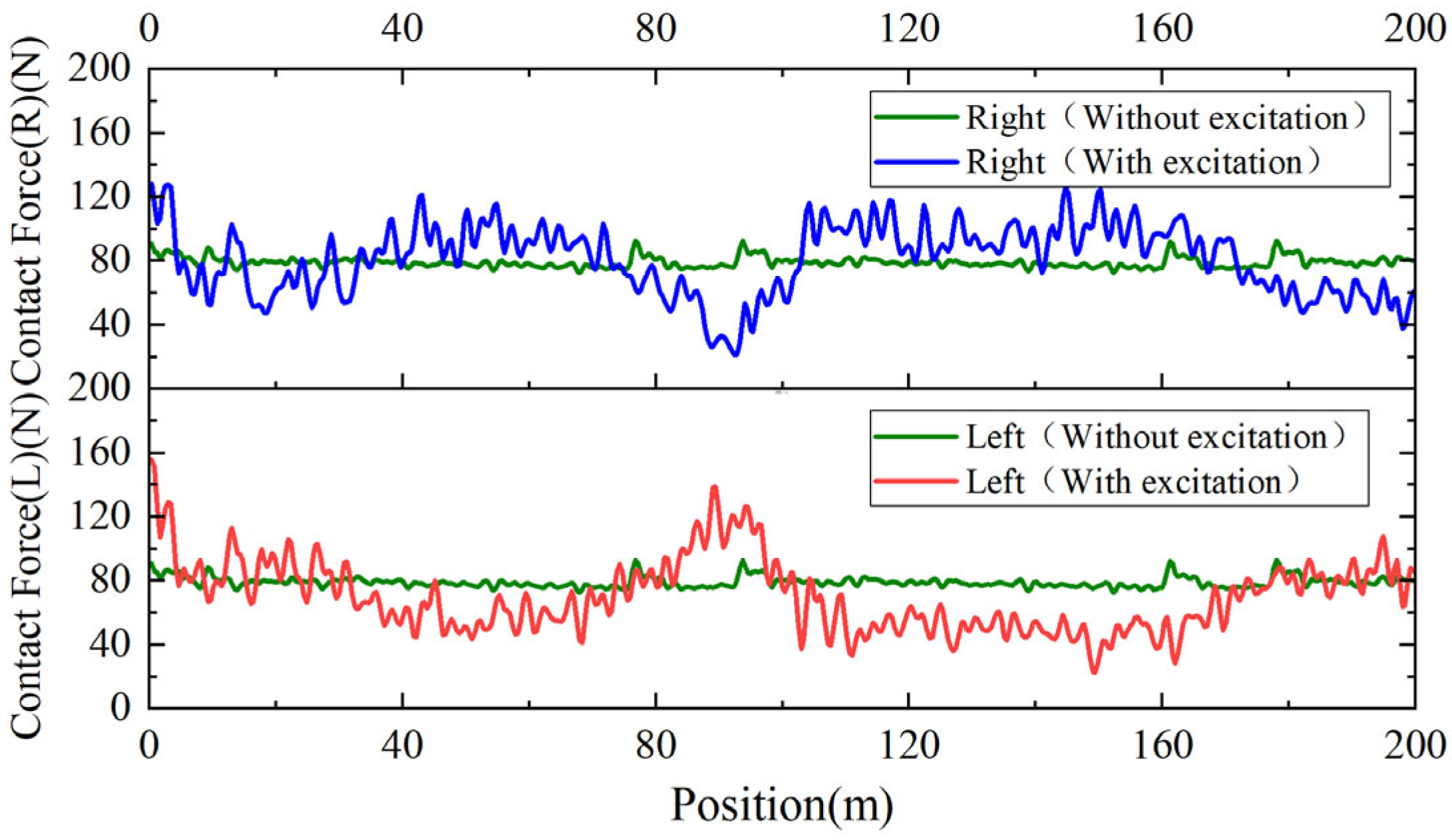
- From the perspective of balancing left–right contact force, as shown in Table 7, the left pantograph head exhibits a higher pan-up contact force Fr and maximum contact force Fmax, but a lower average contact force Fm than the right pantograph. Therefore, to reduce the left pantograph’s Fr and Fmax, and simultaneously increase its average contact force Fm, it is acceptable to slightly increase the right pantograph’s Fr and Fmax to balance the bilateral contact performance.
- From the perspective of engineering feasibility, parameter selection should also consider practical manufacturability and maintainability, aiming to reduce production and maintenance costs.
3.4. Analysis of Optimization Effect
3.5. Sensitivity Analysis of Pantograph Parameters
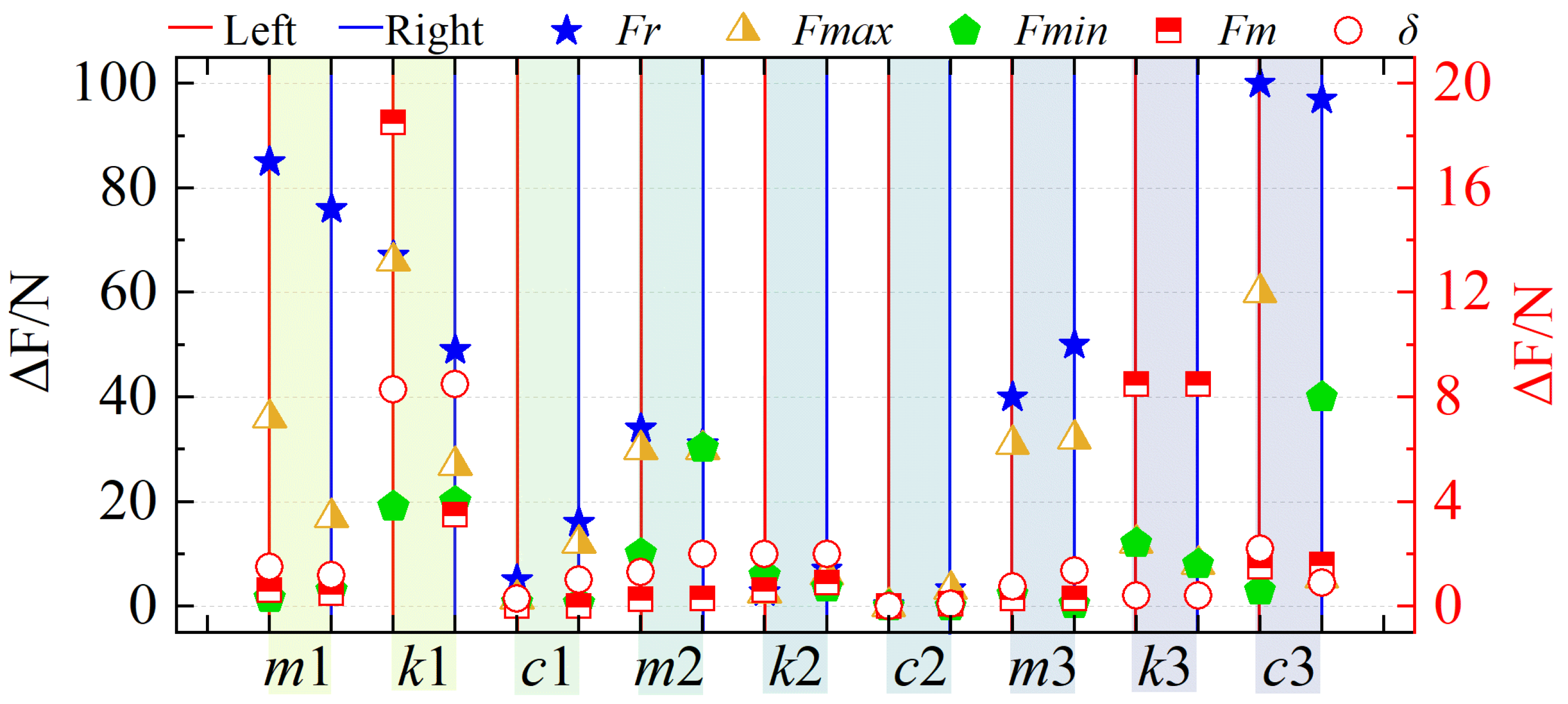
- The lower frame damping (c3) has the most significant impact on the rising contact force (Fr), followed by the pantograph head mass (m1), which is clearly distinguishable from subsequent parameters. The pantograph head stiffness (k1) and the lower frame mass (m3) have comparable effects, while the influence of upper frame mass (m2), lower frame stiffness (k3), and pan-head damping (c1) is relatively minor, with k3 and c1 exhibiting similar levels. Therefore, optimizing the raising contact force should focus primarily on tuning c3 and m1.
- The k1 and c3 exhibit the greatest influence on the maximum contact force (Fmax), while m2 and m3 have comparable but lesser impacts. Other parameters show progressively weaker effects. Since Fmax reflects the extreme conditions of pantograph–catenary interaction, k1 and c3 play a critical role in controlling it. Proper selection of these parameters is necessary to avoid excessive force that could damage components or insufficient force that could disrupt current collection.
- The k1 and m2 are the dominant factors influencing the minimum contact force (Fmin), with significantly greater impact than k3, upper frame stiffness (k2), and c3. Maintaining Fmin within an appropriate range is essential for ensuring uninterrupted current collection. Optimizing k1 and m2 helps reduce the risk of contact loss due to insufficient force.
- The average contact force (Fm) is most strongly affected by the k1, followed by k3, which shows a clear difference from the influence of c3. As Fm is a fundamental indicator of current collection performance, it is primarily governed by stiffness-related parameters such as k1 and k3. Adjusting these parameters can optimize Fm, balancing current quality and mechanical wear, and serving as a critical basis for parameter matching.
- The standard deviation (δ) of contact force is most affected by k1, followed by k2. Other parameters (m2, c3, and m1) have similar but lesser effects, with the least impact observed from m3 relatively. Since δ reflects the stability of current collection, k1 plays a central role in minimizing force fluctuations. Optimizing k1 is therefore critical to improving dynamic current quality and reducing the risk of contact loss.
4. Conclusions
- This study addresses the impact of road surface irregularities on pantograph–catenary interaction performance in electrified roads by developing a coupled dynamic model of the pantograph and catenary system. Road-induced excitation is integrated into the pantograph parameter optimization framework. Simulation results identify a new set of pantograph parameters that significantly improve contact force indicators under both 80 N and 110 N static contact forces, thereby enhancing system adaptability and robustness.
- Sensitivity analysis under road excitation conditions revealed that pantograph head stiffness (k1) is the most critical factor affecting pantograph–catenary interaction, while head damping (c1), upper frame stiffness (k2), and upper frame damping (c2) were found to be insensitive. Among various evaluation metrics, the raising contact force (Fr) is most influenced by the lower frame damping (c3) and pantograph head mass (m1), with effects far exceeding those of other parameters. With the exception of k1 and lower frame stiffness (k3), other parameters had negligible influence on the average contact force (Fm). Moreover, only k1 showed a notable impact on the standard deviation (δ), underscoring its importance in ensuring stable current collection. This finding not only provides a theoretical basis for pantograph parameter design but also offers an important reference for engineering optimization of the power collection system in electrified roads.
Author Contributions
Funding
Data Availability Statement
Conflicts of Interest
References
- Sundelin, H.; Gustavsson, M.G.H.; Tongur, S. The maturity of electric road systems. In Proceedings of the 2016 International Conference on Electrical Systems for Aircraft, Railway, Ship Propulsion and Road Vehicles & International Transportation Electrification Conference (ESARS-ITEC), Toulouse, France, 2–4 November 2016; IEEE: Piscataway, NJ, USA, 2016; pp. 1–5. [Google Scholar]
- Pei, Y.W.; Chen, F.; Ma, T.; Gu, G.H. A comparative review study on the electrified road structures: Performances, sustainability, and prospects. Structures 2024, 62, 106185. [Google Scholar] [CrossRef]
- Zheng, Z.D.; Liu, H.; Li, Y.D.; Xu, Z. Research on electrified road technology. China J. Highw. Transp. 2019, 32, 132–141. [Google Scholar]
- Correcher, A.; Ricolfe-Viala, C.; Tur, M.; Gregori, S.; Salvador-Muñoz, M.; Fuenmayor, F.J.; Gil, J.; Pedrosa, A.M. Hardware-in-the-Loop Test Bench for Simulation of Catenary–Pantograph Interaction (CPI) with Linear Camera Measurement. Sensors 2023, 23, 1773. [Google Scholar] [CrossRef]
- Lee, J.H.; Kim, Y.G.; Paik, J.S.; Park, T.W. Performance evaluation and design optimization using differential evolutionary algorithm of the pantograph for the high-speed train. J. Mech. Sci. Technol. 2012, 26, 3253–3260. [Google Scholar] [CrossRef]
- Pombo, J.; Ambrósio, J. Influence of pantograph suspension characteristics on the contact quality with the catenary for high speed trains. Comput. Struct. 2012, 110–111, 32–42. [Google Scholar] [CrossRef]
- Ambrósio, J.; Pombo, J.; Pereira, M. Optimization of high-speed railway pantographs for improving pantograph-catenary contact. Theor. Appl. Mech. Lett. 2013, 3, 013006. [Google Scholar] [CrossRef]
- Jiang, J.; Liu, Z.G.; Lu, X.B.; Duan, P.C.; Song, Y. Study on matching between pantograph parameters and dropper spacing considering amplitude-frequency characteristics of pantograph. J. Vib. Shock 2016, 35, 134–139. [Google Scholar]
- Qi, W.Y.; Wang, J.W.; Zhang, S.Y.; Huang, Z. Sensitivity analysis and optimal design of pantograph parameters in urban rail transit. Noise Vib. Control 2022, 42, 190–195, 250. [Google Scholar]
- Wu, M.Z.; Liu, Y.; Xu, X.H. Sensitivity analysis and optimization of dynamic parameters in high-speed pantograph-catenary systems. Acta Mech. Sin. 2021, 53, 75–83. [Google Scholar]
- Wang, H.L.; Zheng, D.Y.; Huang, P.; Yan, W.Y. Design optimisation of railway pantograph-catenary systems with multiple objectives. Veh. Syst. Dyn. 2023, 61, 2953–2975. [Google Scholar] [CrossRef]
- Wu, M.Z.; Xu, X.H.; Yan, Y.Z. Multi-parameter joint optimization for double-strip high-speed pantographs to improve pantograph-catenary interaction quality. Acta Mech. Sin. 2022, 38, 521344. [Google Scholar] [CrossRef]
- Chen, K.; Song, Y.; Lu, X.B.; Duan, F.C. Sensitivity Analysis and Optimisation of Key Parameters for Railway Rigid Overhead System and Pantograph. Sustainability 2023, 15, 6803. [Google Scholar] [CrossRef]
- Kim, J.W.; Yu, S.N. Design variable optimization for pantograph system of high-speed train using robust design technique. Int. J. Precis. Eng. Manuf. 2013, 14, 267–273. [Google Scholar] [CrossRef]
- Zhou, N.; Zhang, W. Investigation on dynamic performance and parameter optimization design of pantograph and catenary system. Finite Elem. Anal. Des. 2011, 47, 288–295. [Google Scholar] [CrossRef]
- Wang, Y.; Liu, Y.L.; Chen, X.Q. Parameters Matching of Multi-body Pantograph Considering Amplitude and Frequency Characteristics. Mech. Sci. Technol. Aerosp. Eng. 2023, 42, 1409–1415. [Google Scholar]
- Liu, Y.; Wu, M.Z.; Lu, W.; Wu, Z.G. Multiple dynamics parameters optimization analysis of high-speed pantograph. J. Hefei Univ. Technol. (Nat. Sci.) 2023, 46, 670–677. [Google Scholar]
- Chen, Y.; Lu, J.; Luo, Q.; Zhang, W.; Zhang, C.Z.; Mei, G.M. Study on dynamic characteristic and parameter optimization of pantograph head with flexible model taken into consideration. J. Mach. Des. 2025, 42, 36–43. [Google Scholar]
- Zhou, N.; Li, R.P.; Zhang, W.H. Modeling and simulation of catenary system based on the negative sag method. J. Traffic Transp. Eng. 2009, 9, 28–32. [Google Scholar]
- Guan, J.F.; Wu, J.Q. Establishment and validation of dynamic simulation model of pantograph-catenary system. J. Railw. Sci. Eng. 2017, 14, 2444–2451. [Google Scholar]
- Zhang, X.; Wang, T.S. Computational Dynamics; Tsinghua University Press: Beijing, China, 2007. [Google Scholar]
- EN50318:2018; Railway Applications–Current Collection Systems-Validation of Simulation of the Dynamic Interaction between Pantograph and Overhead Contact Line. European Parliament: Strasbourg, France, 2018.
- Zhou, N.; Zhi, X.S.; Zhang, J.; Zheng, W.; Luo, C.J.; Zhang, W.H. Friction and Wear Performance of Pantograph-Catenary System in Electrified Railways: State of the Art. J. Southwest Jiaotong Univ 2024, 59, 990–1005, 1022. [Google Scholar]
- Zhang, Y.Y.; Li, C.H.; Pang, X.J.; Song, C.F.; Ni, F.; Zhang, Y.Z. Evolution processes of the tribological properties in pantograph/catenary system affected by dynamic contact force during current-carrying sliding. Wear 2021, 477, 1–9. [Google Scholar] [CrossRef]
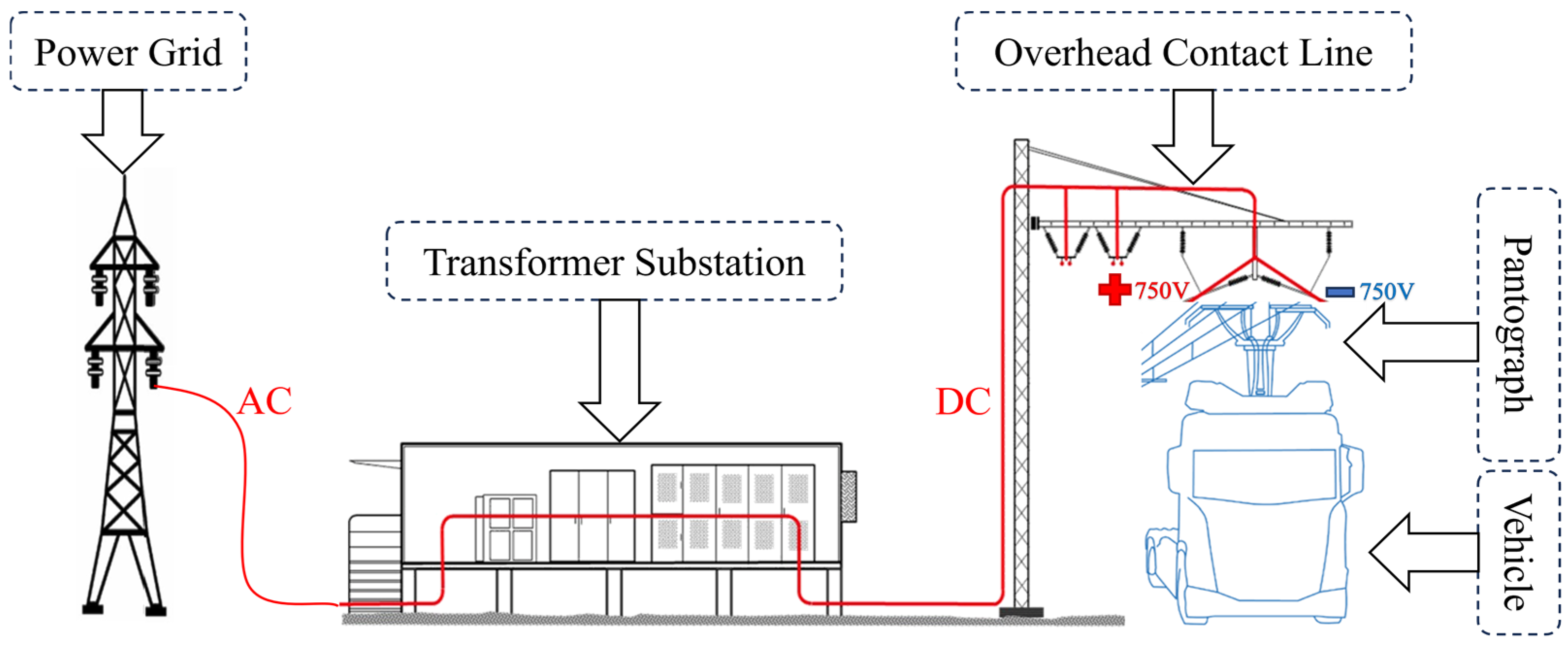





| Operating Parameters | Value | Operating Parameters | Value |
|---|---|---|---|
| Catenary Voltage | DC1500 V | On-board Battery Capacity | 100 kWh |
| Loop Resistance | 0.15 Ω/km | Substation Power | 4 MW |
| Line current | 1100 A | Pantograph current | 240 A |
| Road Surface Smoothness | Vehicle Deformation Level | Pantograph–Catenary Design | |
|---|---|---|---|
| Railway System | 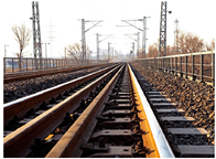 |  |  |
| High smoothness | Relatively small | Single pantograph–single wire | |
| Electrified Road System | 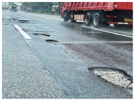 |  | 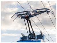 |
| Inevitably uneven | Relatively large | Dual pantograph–dual wire |
| Pantograph Head Parameter | Value | Upper Frame Parameter | Value | Lower Frame Parameter | Value |
|---|---|---|---|---|---|
| m1 (kg) | 7.94 | m2 (kg) | 8.22 | m3 (kg) | 5.9 |
| k1 (N/m) | 6650 | k2 (N/m) | 13,181 | k3 (N/m) | 74 |
| c1 (N·s/m) | 85.31 | c2 (N·s/m) | 11.9 | c3 (N·s/m) | 67.41 |
| Contact Wire | Messenger Wire | Dropper | |||
|---|---|---|---|---|---|
| Young’s modulus (GPa) | 120 | Young’s modulus (GPa) | 120 | Young’s modulus (GPa) | 105 |
| Poisson’s ratio | 0.3 | Poisson’s ratio | 0.3 | Poisson’s ratio | 0.3 |
| Linear density (kg/m) | 1.35 | Linear density (kg/m) | 1.07 | Linear density (kg/m) | 0.089 |
| Tension (kN) | 20 | Tension (kN) | 16 | Catenary span (m) | 50 |
| Cross-sectional Area(m2) | 151 × 10−6 | Cross-sectional Area(m2) | 147 × 10−6 | Height between wires (m) | 1.6 |
| Dropper spacing (m) | 5, 8, 8, 8, 8, 8, 5 | ||||
| Static Contact Force: 80 N Speed: 60 km/h | Without Excitation | With Excitation | |
|---|---|---|---|
| Pantograph (N) | Left Pantograph (N) | Right Pantograph (N) | |
| Contact Force during Raising (N) | 91.14 | 155.74 | 128.51 |
| Average Contact Force (N) | 79.13 | 69.86 | 80.98 |
| Standard Deviation (N) | 3.25 | 21.96 | 21.74 |
| Maximum Contact Force (N) | 92.85 | 155.74 | 127.53 |
| Minimum Contact Force (N) | 72.55 | 22.62 | 21.41 |
| Contact Loss Rate (%) | 0 | 0 | 0 |
| Pantograph Head Parameter | Range | Upper Frame Parameter | Range | Lower Frame Parameter | Range |
|---|---|---|---|---|---|
| m1 (kg) | 3~12 | m2 (kg) | 5~14 | m3 (kg) | 3~18 |
| k1 (N/m) | 3000~16,000 | k2 (N/m) | 8000~18,000 | k3 (N/m) | 0.1~130 |
| c1 (N·s/m) | 0~100 | c2 (N·s/m) | 0~50 | c3 (N·s/m) | 10~210 |
| Optimization Goal | Consideration Items | Optimization Trend |
|---|---|---|
| 1. Performance Indicators | Maximum contact force | ↓ Lower is better |
| Minimum contact force | ↓ Lower is better | |
| Contact Force during Raising | ↓ Lower is better | |
| Standard deviation of contact force | ↓ Lower is better | |
| 2. Balancing Left–Right Contact | Left Pantograph Head | |
| Maximum contact force | ↓ Lower is better | |
| Contact Force during Raising | ↓ Lower is better | |
| Average contact force | ↑ Higher is better | |
| Right Pantograph Head | ||
| Maximum contact force | ↑ Slight increase acceptable | |
| Contact Force during Raising | ↑ Slight increase acceptable | |
| 3. Engineering Feasibility | Cost of production and maintenance | Consider economical viability |
| Pantograph Head Parameter | Optimized Value | Upper Frame Parameter | Optimized Value | Lower Frame Parameter | Optimized Value |
|---|---|---|---|---|---|
| m1 (kg) | 6.5 | m2 (kg) | 6 | m3 (kg) | 14 |
| k1 (N/m) | 3000 | k2 (N/m) | 8000 | k3 (N/m) | 0.1 |
| c1 (N·s/m) | 85.31 | c2 (N·s/m) | 11.9 | c3 (N·s/m) | 210 |
| Static Contact Force: 80 N Speed: 60 km/h | Left Pantograph Head (N) | Right Pantograph Head (N) | ||||
|---|---|---|---|---|---|---|
| Before | After | Improvement | Before | After | Improvement | |
| Contact Force during Raising (N) | 155.74 | 102.34 | 34.29% | 128.51 | 103.96 | 19.11% |
| Average Contact Force (N) | 69.86 | 75.21 | 7.61% | 80.98 | 83.01 | 2.51% |
| Standard Deviation (N) | 21.96 | 16.20 | 26.23% | 21.74 | 16.34 | 24.84% |
| Maximum Contact Force (N) | 155.74 | 128.17 | 17.7% | 128.51 | 119.70 | 6.85% |
| Minimum Contact Force (N) | 22.62 | 39.54 | 74.89% | 21.41 | 30.48 | 43.36% |
| Contact Loss Rate (%) | 0 | 0 | 0% | 0 | 0 | 0% |
| Static Contact Force: 110 N Speed: 60 km/h | Left Pantograph Head (N) | Right Pantograph Head (N) | ||||
|---|---|---|---|---|---|---|
| Before | After | Improvement | Before | After | Improvement | |
| Contact Force during Raising (N) | 196.22 | 127.10 | 35.22% | 166.56 | 141.74 | 14.90% |
| Average Contact Force (N) | 97.96 | 105.12 | 7.31% | 109.05 | 112.77 | 3.41% |
| Standard Deviation (N) | 22.97 | 17.27 | 24.81% | 22.64 | 17.44 | 23.0% |
| Maximum Contact Force (N) | 196.22 | 168.75 | 14.00% | 166.56 | 152.73 | 8.31% |
| Minimum Contact Force (N) | 49.41 | 54.09 | 9.47% | 51.87 | 45.08 | −13.1% |
| Contact Loss Rate (%) | 0 | 0 | 0% | 0 | 0 | 0% |
| Static Contact Force: 80 N Speed: 40 km/h | Left Pantograph Head (N) | Right Pantograph Head (N) | ||||
|---|---|---|---|---|---|---|
| Before | After | Improvement | Before | After | Improvement | |
| Contact Force during Raising (N) | 133.91 | 104.49 | 22.04% | 87.98 | 78.09 | 11.24% |
| Average Contact Force (N) | 69.36 | 75.59 | 9.00% | 80.69 | 83.32 | 3.26% |
| Standard Deviation (N) | 21.23 | 14.84 | 29.91% | 20.59 | 14.56 | 29.29% |
| Maximum Contact Force (N) | 142.25 | 117.46 | 17.43% | 147.07 | 112.66 | 23.04% |
| Minimum Contact Force (N) | 30.45 | 43.26 | 42.07% | 25.29 | 35.42 | 39.98% |
| Contact Loss Rate (%) | 0 | 0 | 0% | 0 | 0 | 0% |
| Evaluation Metrics | Sensitivity Ranking of Parameters |
|---|---|
| Contact Force during Raising | c3 > m1 ≫ k1 ≈ m3 > m2 > k3 ≈ c1 |
| Maximum Contact Force | k1 > c3 > m2 ≈ m3 > m1 > k3 |
| Minimum Contact Force | k1 ≈ m2 > k3 > k2 ≈ c3 |
| Average Contact Force | k1 > k3 ≫ c3 |
| Standard Deviation | k1 ≫ k2 > m2 ≈ c3 ≈ m1 > m3 |
Disclaimer/Publisher’s Note: The statements, opinions and data contained in all publications are solely those of the individual author(s) and contributor(s) and not of MDPI and/or the editor(s). MDPI and/or the editor(s) disclaim responsibility for any injury to people or property resulting from any ideas, methods, instructions or products referred to in the content. |
© 2025 by the authors. Published by MDPI on behalf of the World Electric Vehicle Association. Licensee MDPI, Basel, Switzerland. This article is an open access article distributed under the terms and conditions of the Creative Commons Attribution (CC BY) license (https://creativecommons.org/licenses/by/4.0/).
Share and Cite
Yuan, L.; Zhou, W.; Jiang, H.; Ma, Y.; Huang, S. Optimal Design of Dual Pantograph Parameters for Electrified Roads. World Electr. Veh. J. 2025, 16, 535. https://doi.org/10.3390/wevj16090535
Yuan L, Zhou W, Jiang H, Ma Y, Huang S. Optimal Design of Dual Pantograph Parameters for Electrified Roads. World Electric Vehicle Journal. 2025; 16(9):535. https://doi.org/10.3390/wevj16090535
Chicago/Turabian StyleYuan, Libo, Wei Zhou, Huifu Jiang, Yongjian Ma, and Sijun Huang. 2025. "Optimal Design of Dual Pantograph Parameters for Electrified Roads" World Electric Vehicle Journal 16, no. 9: 535. https://doi.org/10.3390/wevj16090535
APA StyleYuan, L., Zhou, W., Jiang, H., Ma, Y., & Huang, S. (2025). Optimal Design of Dual Pantograph Parameters for Electrified Roads. World Electric Vehicle Journal, 16(9), 535. https://doi.org/10.3390/wevj16090535


