Abstract
Interior permanent magnet (IPM) synchronous motors have gained widespread adoption in electric vehicles (EVs) owing to their durable rotor configurations, expansive operational speed range, and superior efficiency. Nonetheless, typical IPM motor designs frequently exhibit high torque ripple and constrained torque density. To address these issues, a torque enhancement method is introduced by applying both filleting and notching techniques to the stator core. These techniques help reshape the magnetic field directly at the stator, allowing for more precise control of torque production and torque ripple reduction while keeping the rotor structure unchanged. Design variables of the stator in a 12-slot/8-pole fractional-slot V-shaped IPM motor are optimized using a multi-objective genetic algorithm based on a sensitivity constraint for unidirectional operation. The electromagnetic performance of the motor is analyzed through 2D finite element simulations for both no-load and loaded scenarios. The proposed motor increases average torque by 2.45% and significantly reduces torque ripple by 47.73% compared to the conventional motor. These reflect a significant advancement in torque capability. Furthermore, the efficiency of the proposed motor reaches 93.8%. The findings suggest the potential of the proposed filleting and notching techniques for torque capability improvement in EV applications.
1. Introduction
Electric vehicles (EVs) have emerged as a prominent sustainable transportation solution owing to their potential to reduce greenhouse gas emissions and improve air quality. Adopting EVs can reduce air pollution and dependence on fossil fuels by displacing conventional internal combustion engine vehicles [1]. Energy efficiency is improved and operating costs are reduced via electric drive systems [2]. Electric motors are advanced in design, which directly contributes to higher performance as well as longer driving ranges [3]. Optimally designed motors can meet both environmental and performance objectives [4]. Critical components in EV powertrains, notably the electric motor and energy storage system, directly influence vehicle performance, operational efficiency, and driving range. Among various motor technologies, permanent magnet (PM) machines have become the preferred choice owing to their exceptional torque density, high efficiency, reliability, reduced acoustic noise, and broad operational speed range [5,6,7,8]. Interior permanent magnet (IPM) machines, characterized by embedded rotor magnets, have been widely adopted for EV applications. They offer superior torque density, effective field-weakening capability, mechanical robustness, and thermal management advantages [9,10,11,12]. Consequently, extensive research over the past decade has concentrated on enhancing IPM machine performance. In particular, many studies have focused on improving torque capability without compromising efficiency.
Two prominent structural modification strategies, filleting and notching topology, have emerged as particularly effective techniques for IPM machine performance enhancement. Filleting techniques, applicable to either the stator or rotor, improve magnetic flux distribution by smoothing flux paths. This approach maximizes flux linkage and torque production without imposing significant manufacturing complexity or cost. Notably, prior investigations have demonstrated substantial improvements in torque density and efficiency. These improvements were achieved through rotor filleting in variable flux machines employing tangentially magnetized PMs [13,14]. Several recent studies have further validated these benefits. For instance, synchronous reluctance machines demonstrated improved efficiency and power factor through a two-step rotor optimization involving filleted slot geometry and optimized barrier designs [15]. A novel IPM rotor configuration utilizing filleting curves and double-tied arch bridges have enabled operation at rotational speeds exceeding 100,000 rpm, validated experimentally [16]. Moreover, innovative post-assembly magnetization strategies employing optimized filleted rotor structures have been successfully developed for high-power IPM applications, significantly enhancing torque performance [17]. Recently, the authors of [18] proposed an asymmetric rotor structure with flux barriers and directional filleting in a flux-intensifying machine, demonstrating Ld greater than Lq and experimentally validating a 5 kW prototype.
Conversely, rotor notching techniques have been extensively employed. Inherent challenges such as cogging torque and torque ripple, known weaknesses in IPM machines, are addressed by the rotor notching technique. In [19], rotor surface auxiliary notches were applied to a V-shaped IPM design, reducing cogging torque by over 75 percent and torque ripple by nearly 10 percentage points. A multi-objective layered optimization framework combining the Taguchi method and response surface analysis was developed in [20] to refine notch parameters and enhance torque. In [21], seagull optimization and response surface methodology were applied to a single-layer IPM design, achieving torque ripple reduction and higher output torque, validated experimentally. In [22], a two-stage optimization strategy for an integrated starter generator incorporated magnetic bridge and q-axis notching schemes, resulting in substantial torque ripple suppression and harmonic reduction. In [23], composed T-shaped rotor notches were optimized using finite element analysis and multi-objective techniques, achieving improved torque quality while maintaining mechanical strength. Asymmetric surface notching was further explored in [24] using a genetic algorithm-assisted grid search, reducing torque ripple by up to 89.71 percent without degrading average torque. In [25], a modified Tesla Model 3 motor with barrier merging and T-shaped notching was optimized using a sensitivity-constrained multi-objective genetic algorithm, achieving significant gains in torque and efficiency. In [26], a method combining an asymmetric stator shoe with stator notching was proposed to reduce cogging torque and torque ripple in an IPM motor. The initial step was to apply notches to the stator teeth, which successfully reduced cogging torque. Subsequently, asymmetric stator shoes were implemented to reduce torque ripple. Their approach primarily focused on reducing torque ripple and cogging torque. However, improvements in torque production were not considered. Among these, notching on the rotor side has been widely used to reduce cogging torque and shape the magnetic field. In contrast, applying notches to the stator offers a different way to control magnetic flux circulation. It directly alters the stator teeth geometry, which affects flux linkage and magnetic interaction between the stator and rotor. In particular, asymmetric notching is implemented in which each tooth is individually optimized, allowing for the fine control of local magnetic reluctance and precise shaping of the flux circulation.
To the best of our knowledge, the application of stator notching and filleting directly to the stator core of IPM machines has yet to be investigated, presenting a significant research gap with considerable potential for further improving torque density and magnetic flux utilization. To address this research gap, this study proposes a novel approach integrating both filleting and individually optimized asymmetric notching techniques to the stator core of a 12-slot/eight-pole fractional-slot V-shaped IPM motor for unidirectional operation. This approach enables the precise, localized control of flux paths, improving magnetic field shaping and torque performance. This combined implementation, which has not been previously explored, is expected to enhance the motor’s torque performance significantly. Key structural and geometric parameters related to the proposed stator modifications are optimized using a multi-objective optimization approach. The electromagnetic characteristics of the optimized motor configuration are rigorously assessed through two-dimensional finite element analysis (FEA).
The remainder of this paper is structured as follows: Section 2 presents the proposed motor topology. Section 3 describes the detailed design workflow and the multi-objective optimization methodology. Section 4 discusses the electromagnetic performance evaluation results and comparative analyses, and Section 5 summarizes the key findings and provides recommendations for future research.
2. Motor Topologies
This research adopts the 12-slot/eight-pole fractional-slot V-shaped IPM motor from the previous study [27] as the conventional motor, as illustrated in Figure 1a. This design delivers notably superior torque density compared to many commercially available EV motors.
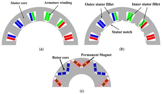
Figure 1.
Cross-sectional perspective of 12-slot/8 rotor pole V-shaped IPM motor: (a) conventional stator design; (b) proposed stator with slot filleting and asymmetric notching design; (c) rotor configuration of V-shaped NdFeB magnets with yellow arrows indicating magnetization direction.
Figure 1b presents the proposed stator with slot filleting and asymmetric notching applied to a conventional 12-slot stator. The filleting technique is applied to the winding slot yoke and tooth tip of the stator. It is hypothesized that enlarging the stator area will increase the flux concentration at some critical points and improve the smoothness of the magnetic flux path. In this design, fillets are implemented at two key sharp-angle regions of the stator geometry. The first fillet is established at the position where the stator yoke intersects the outer stator slot surface, which is referred as the outer stator fillet. The second fillet is at the intersection between the stator tooth tip and the inner part of the stator slot, termed the inner stator fillet. The radius of each fillet is defined as the distance from the center of the arc to the surface curve that replaces the original sharp corner.
The stator’s notching technique is applied to teeth of the stator. It is hypothesized that this will improve the magnetic flux distribution between the stator and rotor, which enhances the reluctance torque and total torque. Notches are applied to all stator teeth, with each tooth having an independent angle, representing an asymmetric notching configuration. This approach provides design flexibility and allows for the fine tuning of the magnetic response. Each notch angle is measured relative to the center line of its corresponding tooth to identify an optimal configuration for torque performance. Based on the above hypothesis, the proposed combination of stator filleting and notching designs has the potential to improve magnetic flux distribution, enhance flux concentration, and reduce flux leakage through the structure. Figure 1c depicts the rotor configurations. Both designs employ an eight-pole, V-shaped IPM rotor. Adjacent permanent magnets are magnetized in opposite directions, forming flux barriers on both sides of each magnet pair.
Table 1 summarizes the essential specifications for both the conventional and the proposed motor. For a rigorous comparative evaluation, the stator and rotor diameters, axial length, magnet volume, and material properties were kept identical. Variations were introduced in the size and position of the stator slot filleting and stator notching. Subsequent sections detail the optimization process applied to the proposed stator structure to maximize torque capabilities and validate the design’s practical effectiveness.

Table 1.
Specifications for the conventional motor compared with the proposed motor.
3. Optimization Methodology
To optimize the performance of the proposed 12-slot/eight-pole fractional-slot V-shaped IPM motor for unidirectional operation, which incorporates filleting and notching at the stator, a multi-objective genetic algorithm (MOGA) was applied to systematically refine critical design variables base on FEA results. The MOGA can efficiently handle multiple conflicting objectives and identify a diverse Pareto front of optimal solutions. This approach is particularly suitable for complex optimization problems. Figure 2 depicts the optimization process as follows:
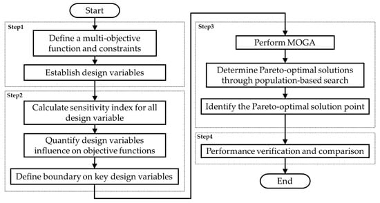
Figure 2.
Schematic of the optimization process.
- Step 1:
- Define the optimization objectives and constraints.
- Step 2:
- Select key design variables and perform a sensitivity analysis.
- Step 3:
- Execute structural optimization through MOGA and extract optimal solutions from Pareto fronts.
- Step 4:
- Evaluate optimized design performance in comparison with the conventional motor.
3.1. Objective Function and Constraints
The primary aim of the stator optimization is to enhance the torque performance of the proposed motor by maximizing the average torque and concurrently minimizing the torque ripple. Optimization was conducted under these specific constraints:
- The rated current is maintained at 254.6 A with an operational speed of 2700 rpm.
- The core and magnet materials remain consistent with the conventional design.
- The rotor configuration in the proposed design is comparable to that of a conventional motor.
- The dimensions, including the outer stator diameter, inner stator diameter, and axial length, are identical between the proposed and conventional motors for a valid comparative assessment.
3.2. Design Variables and Sensitivity Analysis
The key design variables for improving torque capability through filleting and notching are shown in Figure 3. These design variables include , defined as the radius of the arc at the outer corner of the stator slot. is defined as the radius of the arc at the inner corner of the stator slot. refers to the radius at the root of the stator tooth notch. Rnt is the radius applied at the tip of the stator tooth notch. is defined as the notch angle at pole , where is [1,2,3…12]. It represents the angular position adjustment of each stator notch from its own reference center plane (defined as 0°), measured relative to the motor center point. It should be noted that the sequence of the reference center plane is arranged in a clockwise direction.
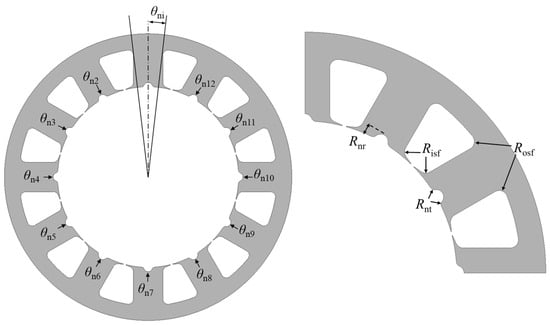
Figure 3.
Illustration of selected design variables for the proposed motor.
A sensitivity analysis was conducted to determine the most impactful design variables and establish their feasible ranges for optimization. Sensitivity indices are calculated using the following equation [28]:
Here, is the initial value of a given design variable and represents variations set at and from the initial value. Figure 4 illustrates the sensitivity indices of each design variable, revealing that and exhibit the top two highest sensitivities to average torque, respectively, while has the highest sensitivity index value to torque ripple. The critically influences magnetic flux paths, directly impacting field distribution and interaction throughout the machine. is vital for flux control, redirecting flux leakage effectively toward the optimal magnetic path. Based on this analysis, Table 2 summarizes the established ranges for the design variable variations. To ensure a more thorough design while also improving optimization efficiency, all design variables were retained. The variation ranges of low-sensitivity indices were reduced. This allowed a more critical design variable to turn more freely within wider bounds. Moreover, individual notch angles were introduced to alter the local magnetic reluctance at the stator tooth. During the sensitivity analysis, twelve notch angles from to were treated as levers acting on flux paths and the air-gap permeance. For each angle, the local reluctance at the stator tooth was modified and flux was steered from saturated corners toward the tooth center. These angles can be asymmetrically adjusted to more precisely guide the magnetic flux circulation, thereby disrupting the stator–slot periodicity. As a result, the dominant low-order slotting harmonics responsible for cogging torque and torque ripple are dephased. This adjustment allows for smoother flux circulation between the rotor and stator, which helps minimize localized magnetic saturation or flux leakage.
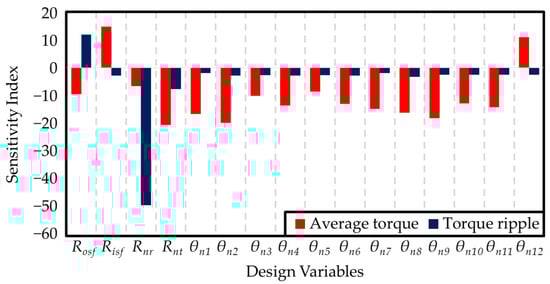
Figure 4.
Sensitivity indices corresponding to individual design variables.
Table 2.
Defined variation ranges and initial and optimal values for each design variable of the proposed motor.
3.3. Optimization of Design Variables Using Multi-Objective Genetic Algorithm
Design variable optimization, informed by the sensitivity results, was executed using the MOGA. Figure 5 presents the optimization algorithm flowchart. MOGA settings include a population size of 1800 individuals, 20 initial generations, mutation probability at 0.02, and crossover probability at 0.98. These values were selected on the basis of preliminary tuning for stable convergence and diverse solutions, with efficient computation. The chosen settings align with typical MOGA configurations used in electrical machine optimization. The optimization process was carried out with convergence achieved around the 900th individual. To ensure reliability, the progression of the Pareto front was monitored throughout all of the generations. This monitoring confirmed that, indeed, the optimization achieved a stable set of results.
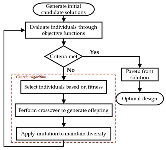
Figure 5.
MOGA optimization flowchart.
Figure 6 displays all generated solutions with the Pareto front highlighted by red dots, facilitating selection of the optimal solution based on balanced average torque and torque ripple criteria. Specifically, the best compromise solution, denoted by the green rectangle, was identified at the Pareto front, characterized by high with a significant reduction in . To perform the optimization, the best compromise on the Pareto front was chosen using the following equation:
where is the objective function to be minimized, and are the initial values of the average torque and torque ripple, respectively, and and are the weight coefficients, where the sum of and is equal to 1.
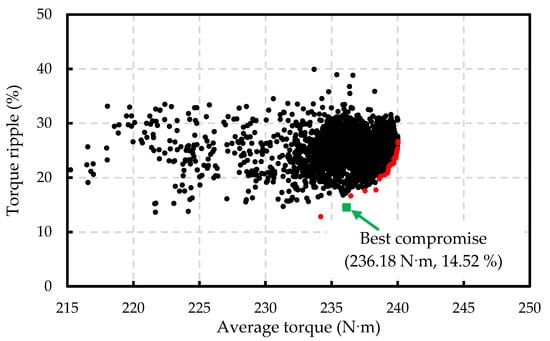
Figure 6.
Pareto fronts (red dots) from MOGA optimization, with black dots representing feasible designs.
The weight coefficients for the multi-objective minimization were set as for and for . These weightings were selected based on preliminary sensitivity studies, which indicated that a greater emphasis on torque yieled the most balanced improvement. This ratio also aligns with the performancde priorities in EV applications to maximize while minimizing at the rated current. The optimized design yielded of 236.18 N·m and of 14.52%, reflecting respective improvements of 2.45% and 47.73% compared to the conventional motor. These results demonstrate a significant reduction in along with improved , thereby aligning effectively with EV performance requirements and optimization constraints. Table 2 summarizes the variations in key design variables and performance metrics between the initial and optimized configurations of the proposed motor.
4. Electromagnetic Performance Comparison
This section rigorously examines the electromagnetic performance of the optimized conventional V-shaped IPM motor using two-dimensional FEA, comparing its outcomes directly against the conventional motor. Both no-load and loaded conditions are analyzed under identical operational parameters, specifically at a current density corresponding to a rated speed of 2700 rpm. The electromagnetic analysis was conducted using 2D transient finite element simulations. Mesh refinement was applied in critical regions including the air gap, stator teeth, permanent magnet edges, and material interfaces to improve accuracy and ensure reliable torque and flux distribution results.
4.1. No-Load Performance
Figure 7 compares the magnetic flux distributions between the conventional and proposed motor configurations. The upper half presents magnetic flux lines, whereas the lower half illustrates B-field saturation. The proposed stator’s filleting design replaces the sharp edges with smooth curves by introducing outer and inner stator slot fillets at the respective corners of the stator slot. This modification allows for more uniform flux distribution. It reduces localized magnetic saturation and minimizes flux leakage, resulting in improved flux linkage balance in the stator pole. Moreover, the proposed stator’s notching modification further improves the distribution by diverting flux away from saturated regions, resulting in smoother overall flux circulation. It can be more clearly observed that the sharp outer stator tooth corner that previously caused flux crowding and flux turning is eliminated by stator filleting, with the flux redirected toward the tooth center when combined with stator notching, producing a more uniform flux distribution in the surrounding region at position A. At position B, a lower flux saturation is presented. Additionally, at position C, the magnetic flux exhibits a more significant concentration. Nevertheless, the maximum flux density remains below 2.3 T across all critical regions, confirming that the stator core can maintain electromagnetic linearity under the no-load condition. The saturation profiles confirm uniform magnetic flux distribution within the core of the proposed stator, a favorable characteristic, especially for motors employing concentered windings. Collectively, these structural improvements enhance the overall utilization efficiency of magnetic flux from PMs.
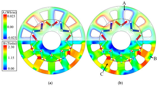
Figure 7.
Open-circuit magnetic flux distribution: (a) conventional motor; (b) proposed motor.
Figure 8 presents a comparison of open-circuit phase Back-electromotive force (Back-EMF) waveforms and corresponding harmonic spectra for both motors. The stator’s filleting and notching modifications effectively alter the magnetic flux path, resulting in changes to the reluctance characteristics of the structure. Although the proposed stator design achieves more uniform flux circulation, the magnetic field at the air-gap becomes slightly distorted due to the asymmetry introduced by the notching technique. This asymmetry increases the spatial harmonic content of the magnetic field, leading to an increase in additional harmonic components of 5th, 7th, 11th, and 13th orders. These components collectively raise the total harmonic distortion (THD) from 8.56% to 17.66%, possibly affecting acoustic noise, inverter control accuracy, and electromagnetic interference. The increased waveform distortion affects sensorless control by reducing the accuracy of zero-crossing detection and introducing phase estimation errors throughout operation. However, advanced PWM techniques or additional filtering strategies can often mitigate these effects. While the overall magnitude (fundamental frequency) of the Back-EMF remains largely unchanged, these two motors achieve a Back-EMF amplitude of 200 V. These design techniques demonstrate improved magnetic flux distribution within the structure, yielding a smoother flux path. Consequently, the enhanced reluctance characteristics contribute to improved electromagnetic performance while maintaining a comparable Back-EMF magnitude.
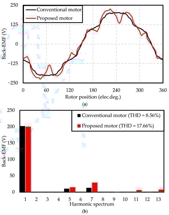
Figure 8.
Comparative open-circuit phase Back-EMF between conventional and proposed motors: (a) waveform profiles; (b) harmonic spectra.
Cogging torque is generated by the magnetic attraction between the PMs installed in the rotor and the stator teeth. It depends on the uniformity of the air-gap permeability within the motor. In the conventional motor, the stator teeth are smooth and symmetric, achieving low cogging torque. With a notching design in the proposed motor, the stator teeth become asymmetrical. This increases the variation in magnetic attraction between the rotor pole and stator pole at different positions, which can cause a slight increase in cogging torque magnitude, as shown in Figure 9. The result shows that the proposed motor exhibits a peak-to-peak cogging torque of 11.65 N·m, which is higher than the 5.14 N·m observed in the conventional configuration. This increase is due to the asymmetrical stator teeth notching, which causes the permeability to be inconsistent and increases the position-dependent magnetization force. However, cogging torque is most evident near standstill and is decreased under load as well as by the reduction gear and driveline compliance. Thus, this cogging torque level is generally regarded as acceptable for EV applications.
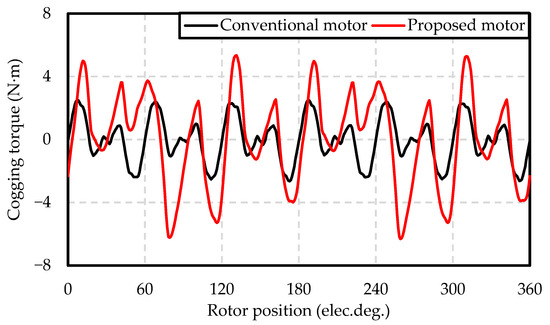
Figure 9.
Comparison of cogging torque profiles between the conventional and proposed motors.
In addition, further reductions can be achieved through appropriate pole–slot selection, slot or magnet skew, and refined tooth-tip shaping.
4.2. On-Load Performance
Figure 10 presents torque waveform comparisons for the conventional and proposed motors. The proposed design delivers a higher of 236.18 N·m, an improvement of 2.45% over the conventional configuration. This improvement is attributed to the smoother flux circulation in the stator, which reduces magnetic saturation and improves magnetic field utilization. Additionally, is superior, decreasing from 27.78% in the conventional motor to 14.52% in the proposed motor. This noticeable reduction in amplitude results from the elimination of localized magnetic saturation at the stator slot corners, which previously caused uneven flux distribution. The filleting and notching modification effectively mitigates this issue and enhances the flux linkage balance among the three-phase windings under load conditions. This is a slight efficiency improvement that aligns closely with the operational demands of EV applications. These outcomes underscore the effectiveness of the stator’s filleting and notching enhancements in significantly advancing torque performance.
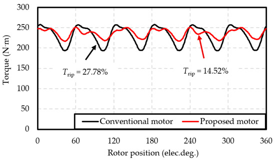
Figure 10.
Comparison of electromagnetic torque waveform between the conventional and proposed motors.
Detailed performance metrics for both motors under rated conditions are summarized in Table 3. The proposed motor demonstrates considerable reductions in both eddy current and hysteresis losses of appoximately of 9% and 5.5%, respectively. The merging of filleting effectively diminishes magnetic flux recirculation within the central region of the V-shaped magnets, thereby significantly reducing eddy current losses. Simultaneously, the notching refines flux paths, minimizing hysteresis losses. Thus, the proposed stator configuration effectively addresses the typical limitations of the conventional V-shaped IPM motor, demonstrating significant potential for further torque performance enhancements in EV motors. While the proposed motor achieves a significant 47.73% reduction in and a 2.45% increase in , it results in an increased THD of the Back-EMF waveform and higher cogging torque. These factors could potentially lead to increased acoustic noise or control complexity. Future research should focus on advanced rotor and stator notching strategies, particularly asymmetric configurations aimed at further refining flux distribution and reducing cogging torque, while a slight reduction in power factor is observed in the proposed motor. This change has a slight impact on the motor’s overall performance. The modified stator geometry with filleting and notching alters the flux distribution and increases the effective d-axis inductance. A higher d-axis inductance requires additional reactive current to establish the magnetic field. Consequently, the power factor is reduced, while the torque-producing component of the current (q-axis) remains unaffected [29,30,31]. Importantly, the motor still maintains good performance with higher torque and reduced torque ripple. Additionally, THD can often be mitigated through advanced inverter control schemes or post-processing filtering techniques, which will be explored in subsequent studies.
Table 3.
Electromagnetic performance at the rated speed of 2700 rpm.
To evaluate the torque capability of the proposed stator configuration against state-of-the-art IPM motor designs, the torque per machine volume and were compared with other IPM motors. Here, stator filleting smooths tooth-tip flux circulation and mitigates local magnetic saturation, while stator notching refines air-gap permeance and suppresses the dominant slotting harmonics that generate torque ripple. The results are summarized in Table 4. A torque-per-volume of 64.6 N·m/L was achieved by the proposed motor. It ranks in the top tier relative to earlier designs that used stator or rotor side modifications. Moreover, a of approximately 14.52% was observed. This level is moderate relative to other IPM motors, but remains acceptable given the achieved torque capability and EV application requirements. These gains are accompanied by higher Back-EMF THD and an increase in cogging torque. Overall, the combined use of stator filleting and stator notching may serve as a useful design option to enhance torque performance.
Table 4.
Comparison of torque performance with other IPM motors.
4.3. Efficiency Map
Figure 11 illustrates the efficiency profiles of both the conventional and proposed motors. It can be observed that the proposed motor delivers slightly higher output torque than the conventional motor throughout low speeds to the rated speed, while maintaining comparable torque at higher speeds. Both motor designs achieve peak efficiency exceeding 96.5%. These results indicate that the proposed stator configuration incorporating stator filleting and asymmetric notching provides robust performance at the rated condition. It also delivers strong performance across varying speeds. This supports the conclusion that the design provides stable and efficient operation, making it well suited for dynamic drive cycles.
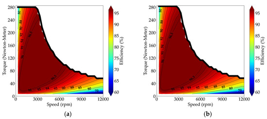
Figure 11.
The efficiency map: (a) conventional motor; (b) proposed motor.
4.4. Mechanical Stress Analysis
The analysis was carried out using electromagnetic equivalent loads at the rated operating condition to validate the mechanical integrity of the proposed stator configuration. As shown in Figure 12, the stress distribution reveals two critical regions. The localized concentration appears first at position A, concentrating near the notched stator teeth’s root with 3.23 MPa. The second is at position B, where the magnet supporting rib experiences a higher localized stress of 6.92 MPa in the proposed motor, compared to about 5.07 MPa in the conventional design. However, both stress values remain significantly below the yield strength of the B20AT1500 core steel, which is approximately 530 MPa. Therefore, they are within the elastic range and will not cause permanent deformation. This indicates that the proposed motor maintains sufficient mechanical stress for EV applications despite the inclusion of these stator modifications.
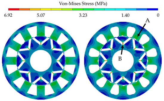
Figure 12.
Von Mises stress distribution under rated torque conditions: (A) conventional motor; (B) proposed motor.
5. Conclusions
This study introduced the implementation of filleting and notching techniques applied to the conventional stator core of the 12-slot/eight-pole fractional-slot V-shaped IPM motor for torque capability enhancement. A comprehensive sensitivity analysis of structural design variables preceded optimization, which utilized the MOGA aimed at simultaneously maximizing average torque and minimizing torque ripple. The optimized structure’s electromagnetic performance was evaluated via 2D finite element simulations under uniform rated current and speed conditions. The results indicated substantial improvements, including the fundamental Back-EMF amplitude remaining essentially unchanged, a 2.45% enhancement in average torque, and a significant 47.73% decrease in torque ripple compared to the conventional motor. The efficiency map indicated higher average torque up to the rated speed and comparable torque at high speed. A torque-per-volume of 64.6 N·m/L was achieved, placing the design in the top tier relative to earlier motors that relied on stator or rotor modifications. These results meet the stated objectives of increasing average torque and reducing torque ripple. Furthermore, the optimized design exhibited reduced losses due to more efficient core material utilization, achieving an efficiency of 93.8%, surpassing the conventional motor. Detailed analyses confirmed that the proposed stator with filleting and notching effectively optimized magnetic flux distribution. These configurations enable the precise and localized control of magnetic flux circulation, improving magnetic field shaping and torque performance. The proposed motor maintains the manufacturing feasibility of the V-shaped IPM motor in terms of complexity and manufacturing cost. Under rated electromagnetic loads, the peak von Mises stress at the magnet-supporting rib was 6.92 MPa. This value is far below the yield strength and therefore consistent with elastic behavior. The findings suggest the potential of the proposed filleting and notching combination for torque capability improvement in the V-shaped IPM motor for EV applications.
Additionally, strategies for mitigating THD through advanced inverter control schemes or post-processing filtering techniques will be investigated in subsequent studies to further improve overall performance.
Author Contributions
Conceptualization, S.C., P.K. and P.S.; Methodology, S.C., P.K. and P.S.; Software, S.C., K.T. and K.K.; Supervision, P.S.; Investigation, S.C., P.K. and P.S.; formal analysis, S.C., K.T., K.K., J.J., A.S., P.K. and P.S.; writing—original draft, S.C.; validation, P.S.; funding acquisition, P.K.; writing—review and editing, P.S. All authors have read and agreed to the published version of the manuscript.
Funding
This research was funded by the National Research Council of Thailand (NRCT) under Grant N41A670261 and the Research Fund of the Faculty of Engineering, Khon Kaen University, under the Research Scholarship for Ph.D. Students project under Contract No. Ph.D.-005/2564.
Data Availability Statement
The original contributions presented in the study are included in the article, further inquiries can be directed to the corresponding author.
Conflicts of Interest
The authors declare no conflicts of interest.
References
- Yu, W.; Wu, Z.; Hua, W. Performance Evaluation of Stator/Rotor-PM Flux-Switching Machines and Interior Rotor-PM Machine for Hybrid Electric Vehicles. World Electr. Veh. J. 2023, 14, 139. [Google Scholar] [CrossRef]
- Wang, A.; Jia, Y.; Soong, W.L. Comparison of Five Topologies for an Interior Permanent-Magnet Machine for a Hybrid Electric Vehicle. IEEE Trans. Magn. 2011, 47, 3606–3609. [Google Scholar] [CrossRef]
- Gundogdu, T.; Zhu, Z.-Q.; Chan, C.C. Comparative Study of Permanent Magnet, Conventional, and Advanced Induction Machines for Traction Applications. World Electr. Veh. J. 2022, 13, 137. [Google Scholar] [CrossRef]
- Un-Noor, F.; Padmanaban, S.; Mihet-Popa, L.; Mollah, M.; Hossain, E. A Comprehensive Study of Key Electric Vehicle (EV) Components, Technologies, Challenges, Impacts, and Future Direction of Development. Energies 2017, 10, 1217. [Google Scholar] [CrossRef]
- Chau, K.T.; Chan, C.C.; Liu, C. Overview of Permanent-Magnet Brushless Drives for Electric and Hybrid Electric Vehicles. IEEE Trans. Ind. Electron. 2008, 55, 2246–2257. [Google Scholar] [CrossRef]
- Ning, S.; Seangwong, P.; Fernando, N.; Jongudomkarn, J.; Siritaratiwat, A.; Khunkitti, P. A Novel Double Stator Hybrid-Excited Flux Reversal Permanent Magnet Machine with Halbach Arrays for Electric Vehicle Traction Applications. IEEE Access 2023, 11, 113255–113263. [Google Scholar] [CrossRef]
- Yang, Z.; Shang, F.; Brown, I.P.; Krishnamurthy, M. Comparative Study of Interior Permanent Magnet, Induction, and Switched Reluctance Motor Drives for EV and HEV Applications. IEEE Trans. Transp. Electrif. 2015, 1, 245–254. [Google Scholar] [CrossRef]
- Suphama, M.; Seangwong, P.; Fernando, N.; Jongudomkarn, J.; Siritaratiwat, A.; Khunkitti, P. A Novel Asymmetric Hybrid-Layer Del-Shaped Rotor Interior Permanent Magnet Motor for Electric Vehicles. IEEE Access 2023, 12, 2793–2802. [Google Scholar] [CrossRef]
- Zhang, G.; Jewell, G.W. Combined Electromagnetic and Mechanical Design Optimization of Interior Permanent Magnet Rotors for Electric Vehicle Drivetrains. World Electr. Veh. J. 2023, 15, 4. [Google Scholar] [CrossRef]
- Dai, L.; Gao, J.; Niu, S.; Huang, S. Multi-Electromagnetic Performance Optimization of Double-Layer Interior Permanent Magnet Synchronous Machine. IEEE Trans. Ind. Electron. 2024; in press. [Google Scholar] [CrossRef]
- Huynh, T.A.; Chen, P.-H.; Hsieh, M.-F. Analysis and Comparison of Operational Characteristics of Electric Vehicle Traction Units Combining Two Different Types of Motors. IEEE Trans. Veh. Technol. 2022, 6, 5727–5742. [Google Scholar] [CrossRef]
- Jung, W.-S.; Lee, H.-K.; Lee, Y.-K.; Kim, S.-M.; Lee, J.-I.; Choi, J.-Y. Analysis and Comparison of Permanent Magnet Synchronous Motors According to Rotor Type under the Same Design Specifications. Energies 2023, 16, 1306. [Google Scholar] [CrossRef]
- Ibrahim, M.; Masisi, L.; Pillay, P. Design of Variable Flux Permanent-Magnet Machine for Reduced Inverter Rating. IEEE Trans. Ind. Appl. 2015, 51, 3666–3674. [Google Scholar] [CrossRef]
- Ibrahim, M.; Masisi, L.; Pillay, P. Design of Variable-Flux Permanent-Magnet Machines Using Alnico Magnets. IEEE Trans. Ind. Appl. 2015, 51, 4482–4491. [Google Scholar] [CrossRef]
- Kim, H.; Park, Y.; Oh, S.-T.; Jeong, G.; Seo, U.-J.; Won, S.-H.; Lee, J. Study on Analysis and Design of Line-Start Synchronous Reluctance Motor Considering Rotor Slot Opening and Bridges. IEEE Trans. Magn. 2022, 58, 8103906. [Google Scholar] [CrossRef]
- Chu, G.; Dutta, R.; Xiao, D.; Fletcher, J.E.; Rahman, M.F. Development and Optimization of a Mechanically Robust Novel Rotor Topology for Very-High-Speed IPMSMs. IEEE Trans. Energy Convers. 2023, 38, 1781–1792. [Google Scholar] [CrossRef]
- Tu, Z.; Lv, Y.; Li, X.; Xu, W.; Peng, T.; Han, X.; Ding, H.; Li, L. Design and Experiment of Post-Assembly Magnetization System for a 160-kW Interior Permanent-Magnet Motor. IEEE Trans. Appl. Supercond. 2024, 34, 5202007. [Google Scholar] [CrossRef]
- Hsieh, M.-F.; Huynh, A.T.; Do, V.-V.; Gerada, D.; Gerada, C. Design Optimization of Spoke-Type Flux-Intensifying PM Motor with Asymmetric Rotor Configuration for Improved Performance. IEEE Trans. Magn. 2024, 60, 8203905. [Google Scholar] [CrossRef]
- Wan, X.; Yang, S.; Li, Y.; Shi, Y.; Lou, J. Minimization of Cogging Torque for V-Type IPMSM by the Asymmetric Auxiliary Slots on the Rotor. IEEE Access 2022, 10, 89428–89436. [Google Scholar] [CrossRef]
- Xu, R.; Tong, W. Multi-Objective Hierarchical Optimization of Interior Permanent Magnet Synchronous Machines Based on Rotor Surface Modification. China Electrotech. Soc. Trans. Electr. Mach. Syst. 2022, 6, 352–358. [Google Scholar] [CrossRef]
- Sun, K.; Tian, S. Multiobjective Optimization of IPMSM with FSCW Applying Rotor Notch Design for Torque Performance Improvement. IEEE Trans. Magn. 2022, 58, 8104909. [Google Scholar] [CrossRef]
- Dai, Y.; Lee, D.-W.; Joung, H.-K.; Lee, H.-J. Optimization on Torque Ripple Performance in ISG Motors with Fractional Slot Distributed Windings and Rotor Notching. IEEE Access 2024, 12, 123872–123882. [Google Scholar] [CrossRef]
- Wang, B.; Wang, D.; Peng, C.; Wang, C.; Xu, C.; Wang, X. Interior Permanent Magnet Synchronous Machines with Composed T-Shaped Notching Rotor. IEEE Trans. Ind. Electron. 2024, 71, 5519–5529. [Google Scholar] [CrossRef]
- Bahrami-Fard, M.; Liang, J.; Chen, P.; Hair, C.; Moallem, M.; Pekarek, S.; Fahimi, B. Cogging Torque Minimization Strategies in Interior Permanent Magnet Synchronous Motors. IEEE Access 2025, 13, 49597–49610. [Google Scholar] [CrossRef]
- Lin, H.N.; Seangwong, P.; Fernando, N.; Siritaratiwat, A.; Khunkitti, P. Torque Capability Enhancement of Commercial Interior Permanent Magnet Motors Using T-Shaped Notching and Merged Barrier Rotor Topology. Results Eng. 2025, 26, 105108. [Google Scholar] [CrossRef]
- Moon, J.-H.; Kang, D.-W. Torque Ripple and Cogging Torque Reduction Method of IPMSM Using Asymmetric Shoe of Stator and Notch in Stator. J. Electr. Eng. Technol. 2022, 17, 3465–3471. [Google Scholar] [CrossRef]
- Zhou, C.; Huang, X.; Li, Z.; Cao, W. Design Consideration of Fractional Slot Concentrated Winding Interior Permanent Magnet Synchronous Motor for EV and HEV Applications. IEEE Access 2021, 9, 64116–64126. [Google Scholar] [CrossRef]
- Wang, Q.; Niu, S. A novel hybrid-excited dual-PM machine with bidirectional flux modulation. IEEE Trans. Energy Convers. 2017, 32, 424–435. [Google Scholar] [CrossRef]
- Dmitrievskii, V.; Prakht, V.; Kazakbaev, V.; Anuchin, A. Comparison of Interior Permanent Magnet and Synchronous Homopolar Motors for a Mining Dump Truck Traction Drive Operated in Wide Constant Power Speed Range. Mathematics 2022, 10, 1581. [Google Scholar] [CrossRef]
- Bi, Y.; Fu, W.; Niu, S.; Zhao, X.; Huang, J. Design of a Dual-Set Permanent Magnet Flux-Switching Machine With Enhanced Torque Density and Fault-Tolerance Capability. IEEE Trans. Transp. Electrific. 2024, 10, 9096–9108. [Google Scholar] [CrossRef]
- Khalil, S.A.; Yousif, M.; Tameemi, A.; Khan, F.; Jadoon, U.; Yousaf, M. Design and Optimization of High Torque Density Spoke-Type Inverted V Shape IPMSM with Concentrated Winding for EV Applications. Results Eng. 2025, 26, 105473. [Google Scholar] [CrossRef]


Disclaimer/Publisher’s Note: The statements, opinions and data contained in all publications are solely those of the individual author(s) and contributor(s) and not of MDPI and/or the editor(s). MDPI and/or the editor(s) disclaim responsibility for any injury to people or property resulting from any ideas, methods, instructions or products referred to in the content. |
© 2025 by the authors. Published by MDPI on behalf of the World Electric Vehicle Association. Licensee MDPI, Basel, Switzerland. This article is an open access article distributed under the terms and conditions of the Creative Commons Attribution (CC BY) license (https://creativecommons.org/licenses/by/4.0/).