
Development of an Energy Consumption Minimization Strategy for a Series Hybrid Vehicle


Abstract
1. Introduction
- ▪
- A conventional ISUZU NPR 10 refuse truck was retrofitted into a series hybrid vehicle configuration by replacing the internal combustion engine with an electric motor and generator setup.
- ▪
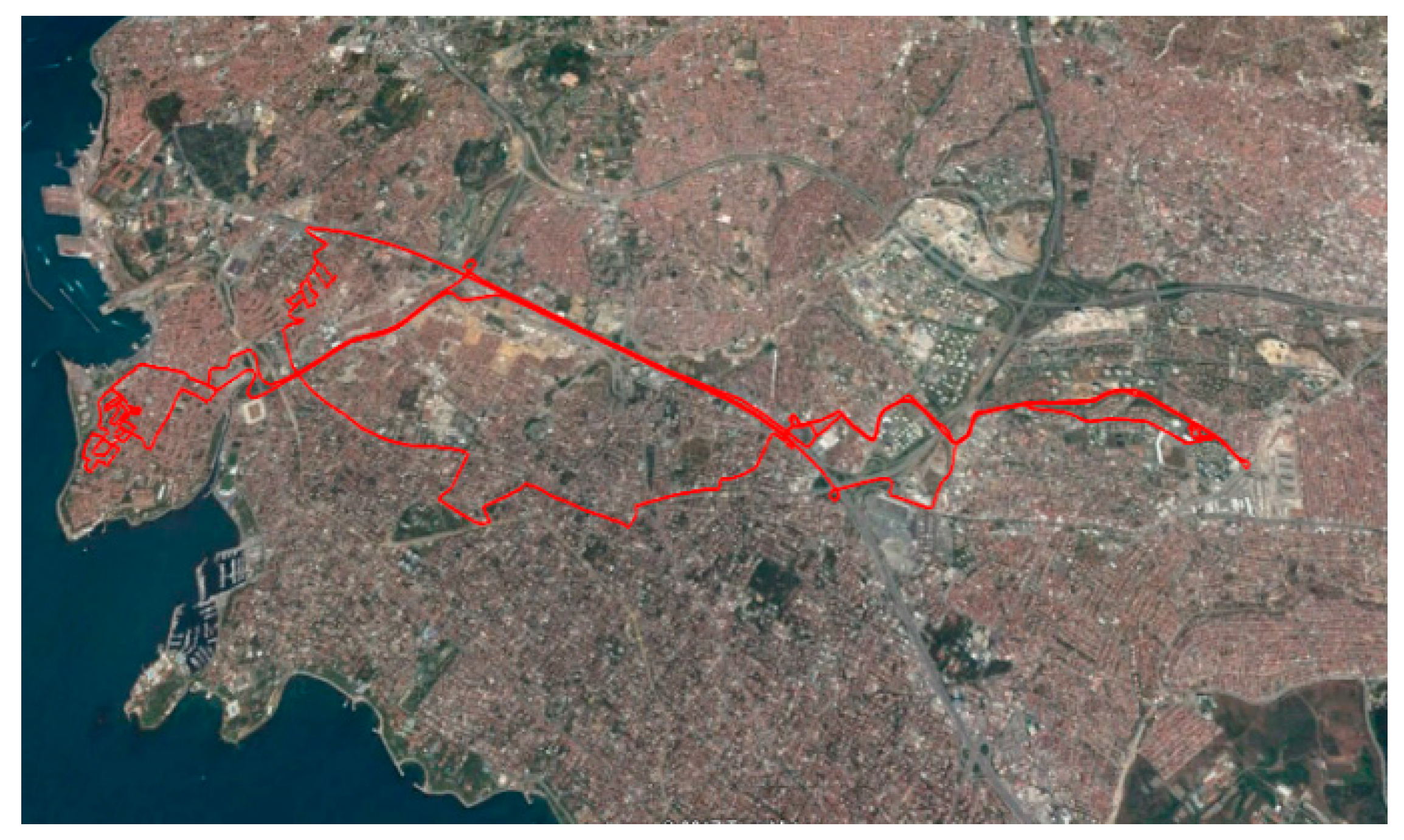
- Real-world driving and operational data were collected from the original ICE-powered vehicle and used to design and tune a vehicle-specific ECMS controller.
- ▪
- The proposed ECMS was evaluated under five driving cycles with different load scenarios (Tare Mass and Gross Vehicle Mass), and its performance was benchmarked against a rule-based controller.
- ▪
- Unlike most ECMS studies focused on passenger cars, this study addresses the unique operational characteristics of refuse trucks, including frequent stopping, idling, and auxiliary energy demands, making it one of the few targeted investigations in this segment.
2. Configuration and Models of SHEV
2.1. Vehicle Dynamic Models
2.2. EM Model
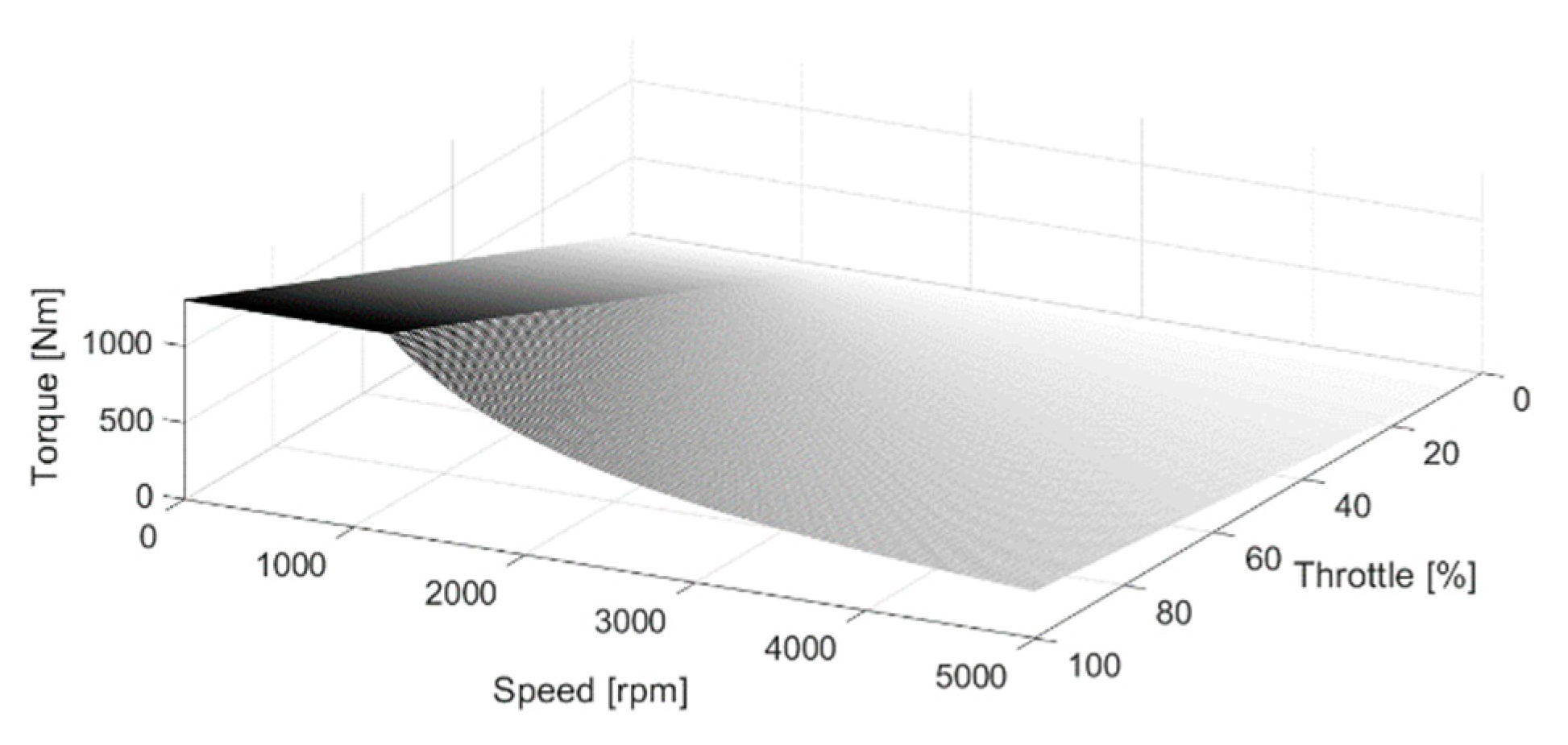
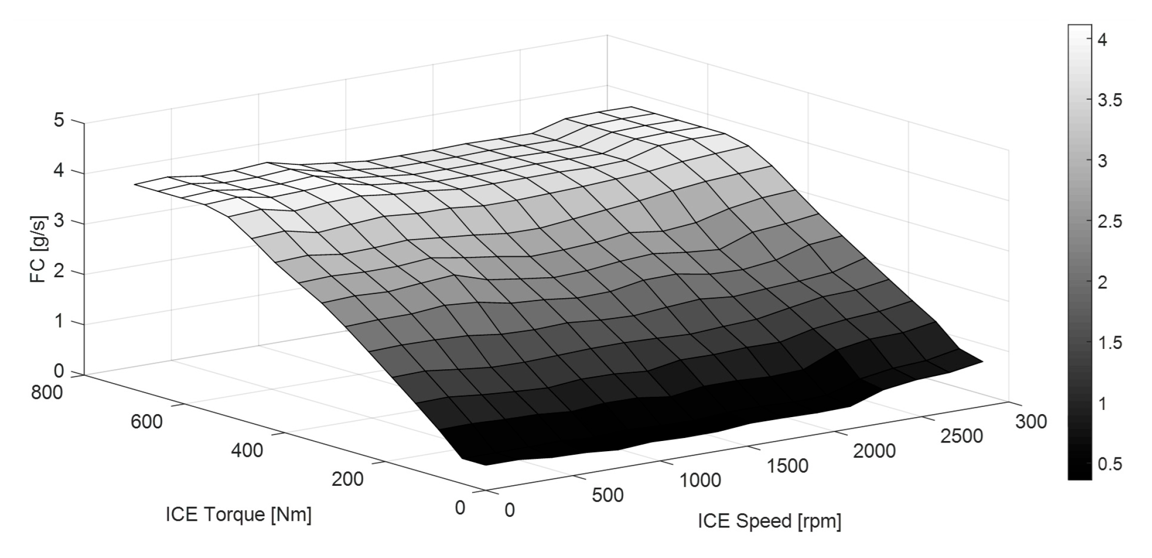
2.3. ICE Model
2.4. Battery Model
2.5. Auxiliary Load Model
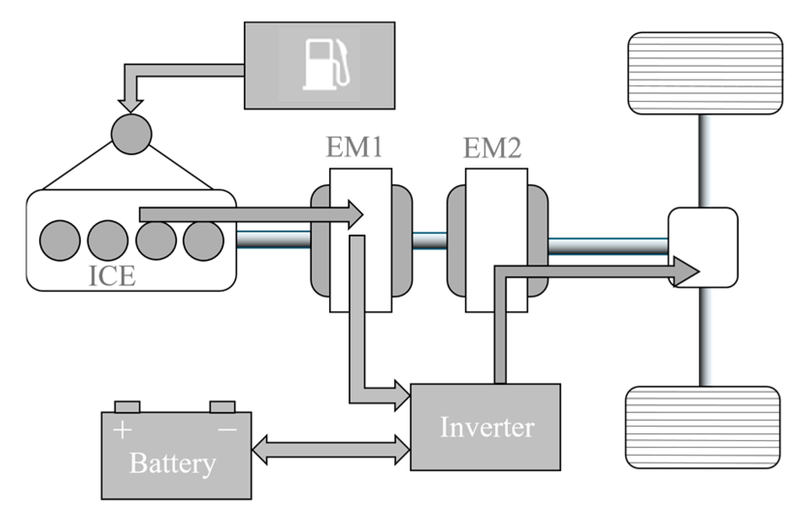
2.6. System Architecture
3. Problem Description
3.1. Pontryagin’s Minimum Principle
3.2. PMP Applied to the Energy Management Problem
4. Simulation Results
5. Conclusions and Discussion
Author Contributions
Funding
Data Availability Statement
Acknowledgments
Conflicts of Interest
Abbreviations
| ECMS | Equivalent Energy Consumption Minimization |
| HEV | Hybrid Electric Vehicle |
| SHEV | Series Hybrid Vehicle |
| TM | Tare Mass |
| GVM | Gross Vehicle Mass |
| PHEV | Parallel Hybrid Vehicle |
| PMP | Pontryagin’s Minimum Principle |
| ICE | Internal Combustion Engine |
| EG | Electric Generator |
| BP | Battery pack |
| SOC | State of Charge |
| BLDC | Brushless Direct Current Motor |
| OCV | Open Circuit Voltage |
| OCB | Orange Country Bus |
| WLTP | Worldwide Harmonized Light-Duty Vehicles Test Procedure |
| NREL | National Renewable Energy Laboratory |
| GENSET | Generator Set |
| PDU | Power Distribution Unit |
References
- de Lucena, S.E. A Survey on Electric and Hybrid Electric Vehicle Technology. In Electric Vehicles-The Benefits and Barriers; Soylu, S., Ed.; Intech: London, UK, 2011. [Google Scholar]
- Chan, C.C. The State of the Art of Electric, Hybrid, and Fuel Cell Vehicles. Proc. IEEE 2007, 95, 704–718. [Google Scholar] [CrossRef]
- Wang, H.; Huang, Y.; Khajepour, A.; Song, Q. Model predictive control-based energy management strategy for a series hybrid electric tracked vehicle. Appl. Energy 2016, 182, 105–114. [Google Scholar] [CrossRef]
- Kim, M.; Jung, D.; Min, K. Hybrid Thermostat Strategy for Enhancing Fuel Economy of Series Hybrid Intracity Bus. IEEE Trans. Veh. Technol. 2014, 63, 3569–3579. [Google Scholar] [CrossRef]
- Jalil, N.; Kheir, N.; Salman, M. A rule-based energy management strategy for a series hybrid vehicle. In Proceedings of the 1997 American Control Conference (Cat. No.97CH36041), Albuquerque, NM, USA, 4–6 June 1997. [Google Scholar]
- Shen, C.; Shan, P.; Gao, T. A Comprehensive Overview of Hybrid Electric Vehicles. Int. J. Veh. Technol. 2011, 2011, 571683. [Google Scholar] [CrossRef]
- Kim, N.; Cha, S.; Peng, H. Optimal Control of Hybrid Electric Vehicles Based on Pontryagin’s Minimum Principle. IEEE Trans. Control Syst. Technol. 2011, 19, 1279–1287. [Google Scholar]
- Tang, L.; Rizzoni, G.; Onori, S. Energy Management Strategy for HEVs Including Battery Life Optimization. IEEE Trans. Transp. Electrif. 2015, 1, 211–222. [Google Scholar] [CrossRef]
- Chen, Z.; Xiong, R.; Wang, K.; Jiao, B. Optimal Energy Management Strategy of a Plug-in Hybrid Electric Vehicle Based on a Particle Swarm Optimization Algorithm. Energies 2015, 8, 3661–3678. [Google Scholar] [CrossRef]
- Boehme, T.J.; Frank, B.; Schori, M.; Jeinsch, T. Multi-objective Optimal Powertrain Design of Parallel Hybrid Vehicles with Respect to Fuel Consumption and Driving Performance. In Proceedings of the European Control Conference (ECC), Strasbourg, France, 24–27 June 2014. [Google Scholar]
- Van Berkel, K.; de Jager, B.; Hofman, T.; Steinbuch, M. Implementation of Dynamic Programming for Optimal Control Problems with Continuous States. IEEE Trans. Control Syst. Technol. 2015, 23, 1172–1179. [Google Scholar] [CrossRef]
- Bertsekas, D.P. Dynamic Programming and Optimal Control, 3rd ed.; Athena Scientific: Belmont, MA, USA, 2005; Volume 1. [Google Scholar]
- Boyd, S.; Vandenberghe, L. Convex Optimization; Cambridge University Press: Cambridge, UK, 2009. [Google Scholar]
- Hadj-Said, S.; Colin, G.; Ketfi-Cherif, A.; Chamaillard, Y. Analytical Solution for Energy Management of Parallel Hybrid Electric Vehicles. IFAC-Pap. 2017, 50, 13872–13877. [Google Scholar] [CrossRef]
- Pham, T.H.; Kessels, J.T.B.A.; van den Bosch, P.P.J.; Huisman, R.G.M. Analytical Solution to Energy Management Guaranteeing Battery Life for Hybrid Trucks. IEEE Trans. Veh. Technol. 2016, 65, 1. [Google Scholar] [CrossRef]
- Egardt, B.; Murgovski, N.; Pourabdollah, M.; Johannesson, L. Electromobility Studies Based on Convex Optimization: Design and Control Issues Regarding Vehicle Electrification. IEEE Control Syst. 2014, 34, 32–49. [Google Scholar] [CrossRef]
- Geng, S.; Schulte, T.; Maas, H. Model-Based Analysis of Different Equivalent Consumption Minimization Strategies for a Plug-In Hybrid Electric Vehicle. Appl. Sci. 2022, 12, 2905. [Google Scholar] [CrossRef]
- Luján, J.M.; Guardiola, C.; Pla, B.; Reig, A. Analytical Optimal Solution to the Energy Management Problem in Series Hybrid Electric Vehicles. IEEE Trans. Veh. Technol. 2018, 67, 6803–6813. [Google Scholar] [CrossRef]
- Vankayala, S.; De Araujo, P.; Zagun, M.; Okarmus, M.; How, J.; Zeman, J. Dynamic Simulation Using ECMS Controller to Optimize the Fuel Economy of a Fuel Cell based HD Commercial Vehicle; SAE Technical Paper 2023-01-0497; SAE International: Warrendale, PA, USA, 2023. [Google Scholar] [CrossRef]
- Xiong, H.; Fu, B.; Huang, Z. Real-Time Control Strategy for CVT-Based Hybrid Electric Vehicles Considering Drivability Constraints. Appl. Sci. 2019, 9, 2074. [Google Scholar]
- Schulze, S.; Feyerl, G.; Pischinger, S. Advanced ECMS for Hybrid Electric Heavy-Duty Trucks with Predictive Battery Discharge and Adaptive Operating Strategy under Real Driving Conditions. Energies 2023, 16, 5171. [Google Scholar] [CrossRef]
- Road Vehicles—Functional Safety Parts 1–10. ISO/DIS 26262; 2009. Available online: https://www.iso.org/publication/PUB200262.html (accessed on 24 June 2025).
- Kannenberg, C.; Lange, E. Konventioneller Antriebsstrang und Hybridantriebe; Bosch Automotive Information; Vieweg+ Teubner: Wiesbaden, Germany, 2010; ISBN 978-3-8348-1303-9. [Google Scholar]
- Gol, M.; İnal, T.; Hartavi, A.E. An Effective Tool for Evaluating the Impact of E-Powertrain on Energy Consumption and Performance. In Proceedings of the OTEKON’14, Bursa, Turkey, 26 May 2014. [Google Scholar]
- Chaim, M.; Shmerling, E. A Model of Vehicle Fuel Consumption at Conditions of the EUDC. Int. J. Mech. 2013, 7, 10–17. [Google Scholar]
- Williamson, S.S.; Emadi, A.; Rajashekara, K. Comprehensive Efficiency Modeling of Electric Traction Motor Drives for Hybrid Electric Vehicle Propulsion Applications. IEEE Trans. Veh. Technol. 2007, 56, 1561–1572. [Google Scholar] [CrossRef]
- Cancelli, D. Experimental Assessment of Power Split Strategies for Hybrid Electric Drivetrain. Master’s Thesis, Polytechnic University of Torino, Turin, Italy, 2016. [Google Scholar]
- Tremblay, O.; Dessaint, L.-A. Experimental Validation of a Battery Dynamic Model for EV Applications. World Electr. Veh. J. 2009, 3, 289–298. [Google Scholar] [CrossRef]
- Teressa, T.; Chung, H.T.; Shin, K. Study of Battery State-ofcharge Estimation with kNN Machine Learning Method. IEIE Trans. Smart Process. Comput. 2021, 10, 496–504. [Google Scholar]
- Cha, H.-R.; Angani, A.; Hwang, M.-H. Thermal management of lithium-ion batteries by novel designs of wavy cold plates: Performance comparison. J. Energy Storage 2023, 73, 109303. [Google Scholar] [CrossRef]
- Andersson, C. On Auxiliary Systems in Commercial Vehicles. Ph.D. Thesis, Department of Industrial Electrical Engineering and Automation, Lund University, Lund, Sweden, 2004. [Google Scholar]
- Pettersson, N.; Johansson, K. Modelling and control of auxiliary loads in heavy vehicles. Int. J. Control. 2006, 79, 479–495. [Google Scholar] [CrossRef]
- Pontryagin, L.S.; Boltyanskii, V.G.; Gamkrelidze, R.V.; Mishechenko, E.F. The Mathematical Theory of Optimal Processes; Interscience: New York, NY, USA, 1962. [Google Scholar]
- Bryson, A.E.; Ho, Y.-C. Applied Optimal Control: Optimization, Estimation, and Control; Routledge: London, UK, 1975. [Google Scholar] [CrossRef]
- Serrao, L.; Onori, S.; Rizzoni, G. ECMS as a realization of Pontryagin’s minimum principle for HEV control. In Proceedings of the American Control Conference, St. Louis, MO, USA, 10–12 June 2009. [Google Scholar]
- Barsali, S.; Miulli, C.; Possneti, A. A Control Strategy to Minimize Fuel Consumption of Series Hybrid Electric Vehicles. IEEE Trans. Energy Convers. 2004, 19, 187–195. [Google Scholar] [CrossRef]
- Friden, H.; Sahlin, H. Energy Manangement Strategies for Plug-in Hybrid Electric Vehicles. Master’s Thesis, Chalmers University of Technology, Goteborg, Sweden, 2012. [Google Scholar]
- Guardiola, C.; Pla, B.; Onori, S.; Rizzoni, G. A new approach to optimallytune the control strategy for hybrid vehicles applications. IFAC Proc. Vol. 2012, 45, 255–261. [Google Scholar] [CrossRef]
- Kim, N.; Lee, D.; Cha, S.-W.; Peng, H. Optimal control of a plug-in hybrid electric vehicle (PHEV) based on driving patterns. In Proceedings of the EVS’24 International Battery, Hybrid and Fuel Cell Electric Vehicle Symposium, Stavanger, Norway, 13–16 May 2009; pp. 1–9. [Google Scholar]
- Zhang, C.; Vahid, A. Real-time optimal control of plug-in hybrid vehicles with trip preview. In Proceedings of the 2010 American Control Conference, Baltimore, MD, USA, 30 June–2 July 2010; pp. 6917–6922. [Google Scholar]
- Guardiola, C.; Pla, B.; Blanco-Rodríguez, D.; Reig, A. Modelling driving behaviour and its impact on the energy management problem in hybrid electric vehicles. Int. J. Comput. Math. 2014, 91, 147–156. [Google Scholar] [CrossRef]
- Sciarretta, A.; Back, M.; Guzzella, L. Optimal control of parallel hybrid electric vehicles, in Control Systems Technology. IEEE Trans. Control. Syst. Technol. 2004, 12, 352–363. [Google Scholar] [CrossRef]
- Chasse, A.; Corde, G.; Del Mastro, A.; Perez, F. Online optimal control of a parallel hybrid withafter-treatment constraint integration. In Proceedings of the 2010 IEEE Vehicle Power and Propulsion Conference, Lille, France, 1–3 September 2010; pp. 1–6. [Google Scholar]
- U.S. Department of Transportation. Estimated U.S. Average Vehicle Emissions Rates per Vehicle by Vehicle Type Using Gasoline, Diesel, and Electric. Available online: https://www.bts.gov/content/estimated-national-average-vehicle-emissions-rates-vehicle-vehicle-type-using-gasoline-and (accessed on 27 June 2024).
- Mulholland, E.; Ragon, P.L.; Rodríguez, F. CO2 Emissions from Trucks in the European Union: An Analysis of the 2020 Reporting Period. 2023 International Council on Clean Transportation. ICCT20. Available online: https://theicct.org/publication/hdv-co2-emissions-eu-2020-reporting-jul23/ (accessed on 24 June 2025).
- EEA. Transport and Environment Report 2021. Available online: https://www.eea.europa.eu/publications/transport-and-environment-report-2021 (accessed on 27 June 2024).
- Paganelli, G.; Delprat, S.; Guerra, T.; Rimaux, J.; Santin, J. Equivalent Consumption Minimization Strategy for Parallel Hybrid Powertrains. Proceedings of IEEE Vehicular Technology Conference, Birmingham, AL, USA, 6–9 May 2002; pp. 2076–2081. [Google Scholar]
- Pei, D.; Leamy, M. Forward-Looking Simulation of the GM Front-Wheel Drive Two-Mode Power-Split HEV Using a Dynamic Programming-Informed Equivalent Cost Minimization Strategy. SAE Int. J. Alt. Power. 2013, 2, 279–290. [Google Scholar] [CrossRef]


| Parameter | Value | Unit |
|---|---|---|
| Vehicle Mass | 6800, 13,800 | kg |
| Tire Radius | 0.38 | |
| Frontal Area | 4.8 | |
| Rolling Resistance Coeff. | 0.0063 | - |
| Aerodynamic Drag Coeff. | 0.68 | - |
| Differential Ratio | 4.77 | - |
| EM Power | 150 (Cont.) | kW |
| ICE Power | 134 | kW |
| Battery Nominal Voltage | 600 | V |
| Battery Capacity | 42 | Ah |
| ECMS | Rule-Based Controller | ||
|---|---|---|---|
| Range (km) | % | ||
| NREL | 190.3 | 167.37 | 13.5 |
| FTP SC03 | 306.6 | 268.78 | 14 |
| FIGE | 305.1 | 269.44 | 13.23 |
| Orange | 218.6 | 193.70 | 12.8 |
| WLTP | 260.5 | 232.7 | 11.9 |
| ECMS/Rule-Based | |||
|---|---|---|---|
| CO (g/km) | NOx (g/km) | CO2 (g/t-km) | |
| NREL | 1.91/2.01 | 3.97/4.05 | 86.13/92.7 |
| FTP SC03 | 1.61/2.74 | 6.07/7.89 | 89.54/91.3 |
| FIGE | 1.34/1.61 | 6.29/7.86 | 93.47/101.2 |
| Orange | 1.81/2.72 | 3.7/5.66 | 80.57/83.3 |
| WLTP | 1.14/1.54 | 3.0/4.14 | 57.26/79.1 |
Disclaimer/Publisher’s Note: The statements, opinions and data contained in all publications are solely those of the individual author(s) and contributor(s) and not of MDPI and/or the editor(s). MDPI and/or the editor(s) disclaim responsibility for any injury to people or property resulting from any ideas, methods, instructions or products referred to in the content. |
© 2025 by the authors. Published by MDPI on behalf of the World Electric Vehicle Association. Licensee MDPI, Basel, Switzerland. This article is an open access article distributed under the terms and conditions of the Creative Commons Attribution (CC BY) license (https://creativecommons.org/licenses/by/4.0/).
Share and Cite
Göl, M.; Baba, A.F.; Hartavi, A.E. Development of an Energy Consumption Minimization Strategy for a Series Hybrid Vehicle. World Electr. Veh. J. 2025, 16, 383. https://doi.org/10.3390/wevj16070383
Göl M, Baba AF, Hartavi AE. Development of an Energy Consumption Minimization Strategy for a Series Hybrid Vehicle. World Electric Vehicle Journal. 2025; 16(7):383. https://doi.org/10.3390/wevj16070383
Chicago/Turabian StyleGöl, Mehmet, Ahmet Fevzi Baba, and Ahu Ece Hartavi. 2025. "Development of an Energy Consumption Minimization Strategy for a Series Hybrid Vehicle" World Electric Vehicle Journal 16, no. 7: 383. https://doi.org/10.3390/wevj16070383
APA StyleGöl, M., Baba, A. F., & Hartavi, A. E. (2025). Development of an Energy Consumption Minimization Strategy for a Series Hybrid Vehicle. World Electric Vehicle Journal, 16(7), 383. https://doi.org/10.3390/wevj16070383