

Development of an EV Battery Management Display with CANopen Communication

Abstract
1. Introduction
Literature Review
2. CAN Communication Between BMS and Display Units
2.1. CAN
2.2. CANopen
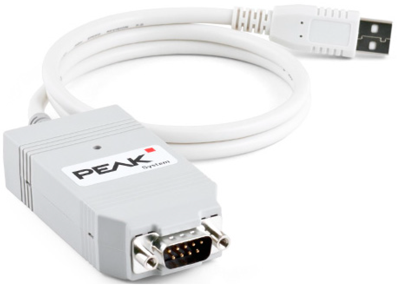
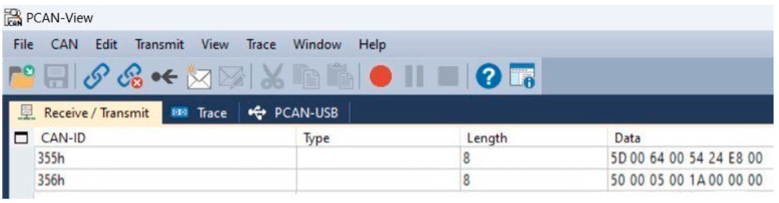
2.3. PCAN-USB
2.3.1. D-Sub Pin Configuration
2.3.2. Key Features of PCAN-USB
2.4. Lithium-Ion Battery with Nickel Manganese Cobalt Oxide (NMC)
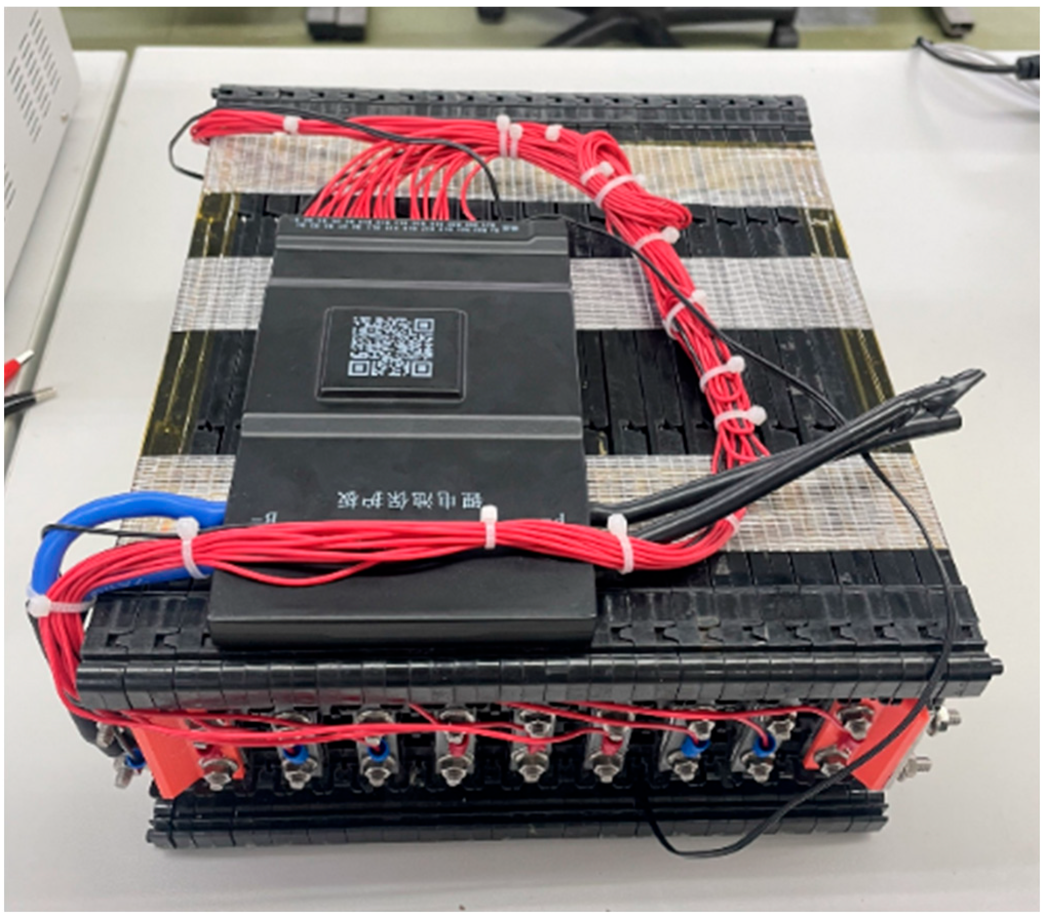
2.5. Lithium Battery Pack Assembly
- Vtotal is the total voltage of the battery pack;
- Ctotal is the total capacity of the battery pack;
- N is the number of cells connected in series;
- Vcell is the voltage of a single cell;
- Ccell is the capacity of a single cell.
2.6. BMS
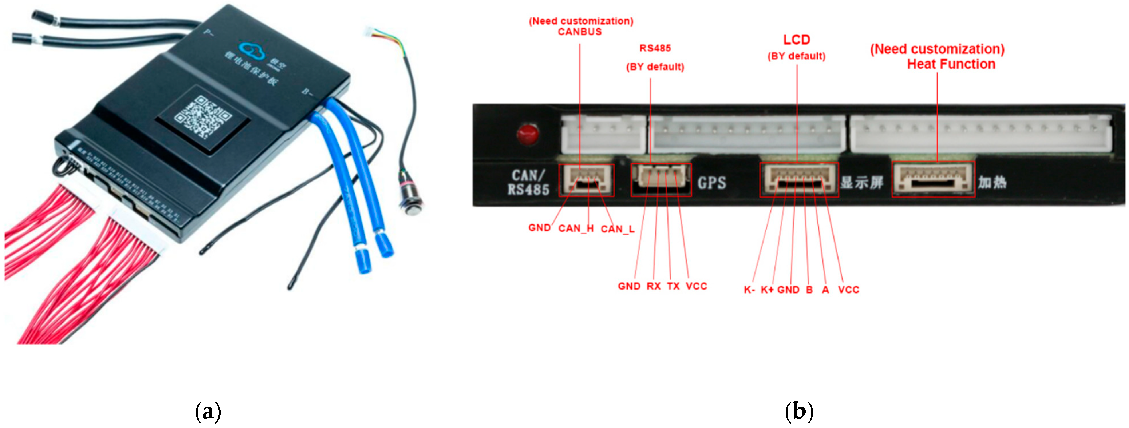
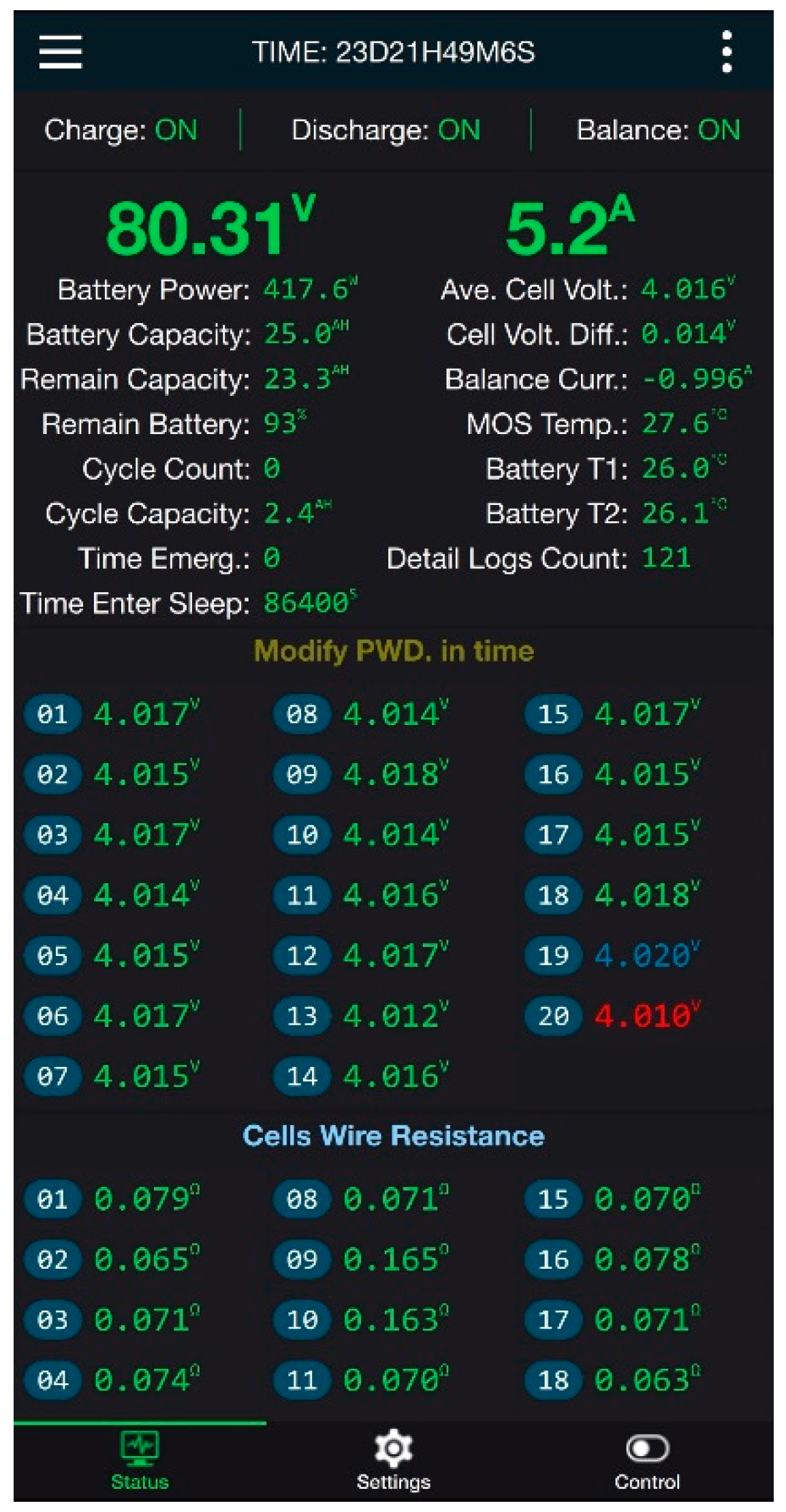
2.7. JK BMS (JiKong Battery Management System)
2.8. UART
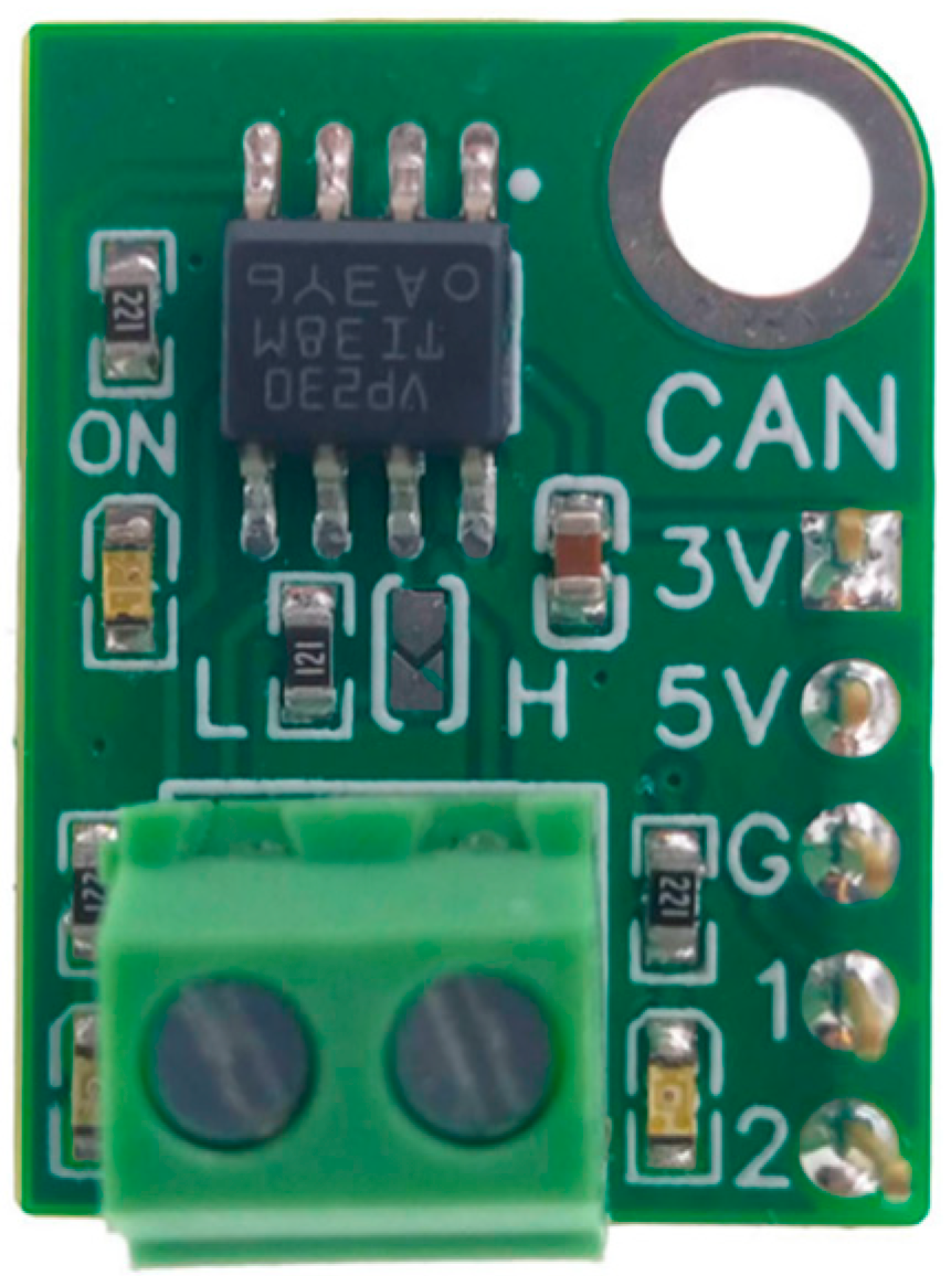
2.9. TJA1051 Transceiver Module
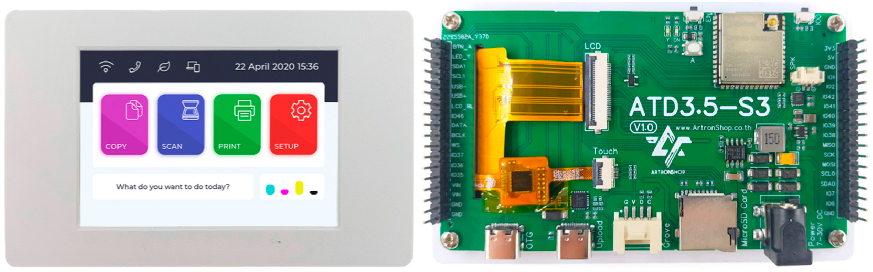
2.10. ATD3.5-S3 Display Module
2.11. CAN Bus Expansion Module for ATD3.5-S3
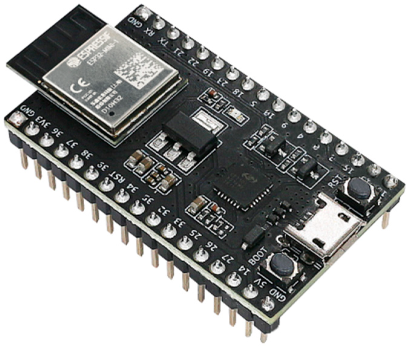
2.12. ESP32 Module
2.13. Buck Converter or Step-Down Converter
3. Methodology
3.1. Electrical Circuit Design
3.2. Testing and Evaluation Method
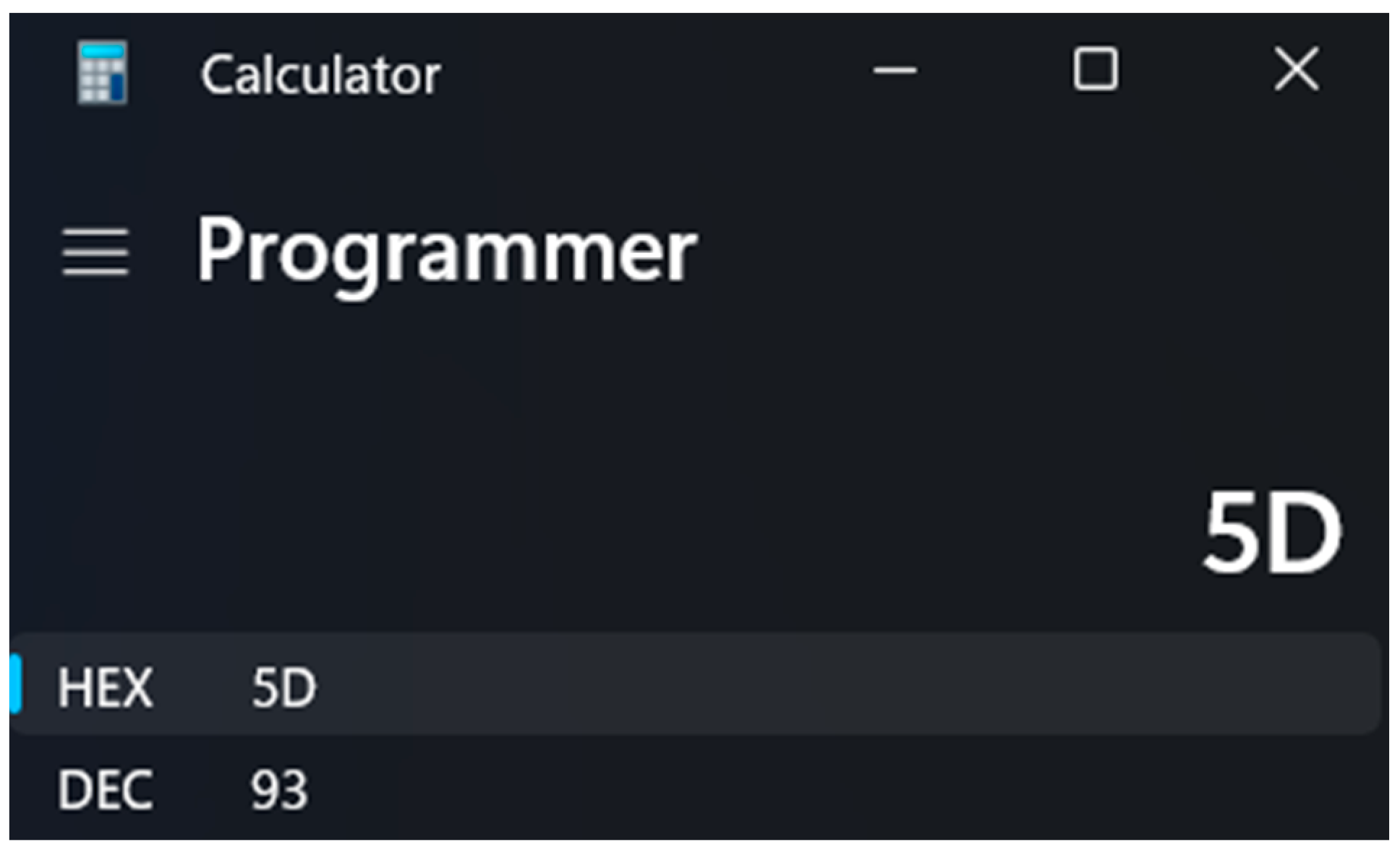
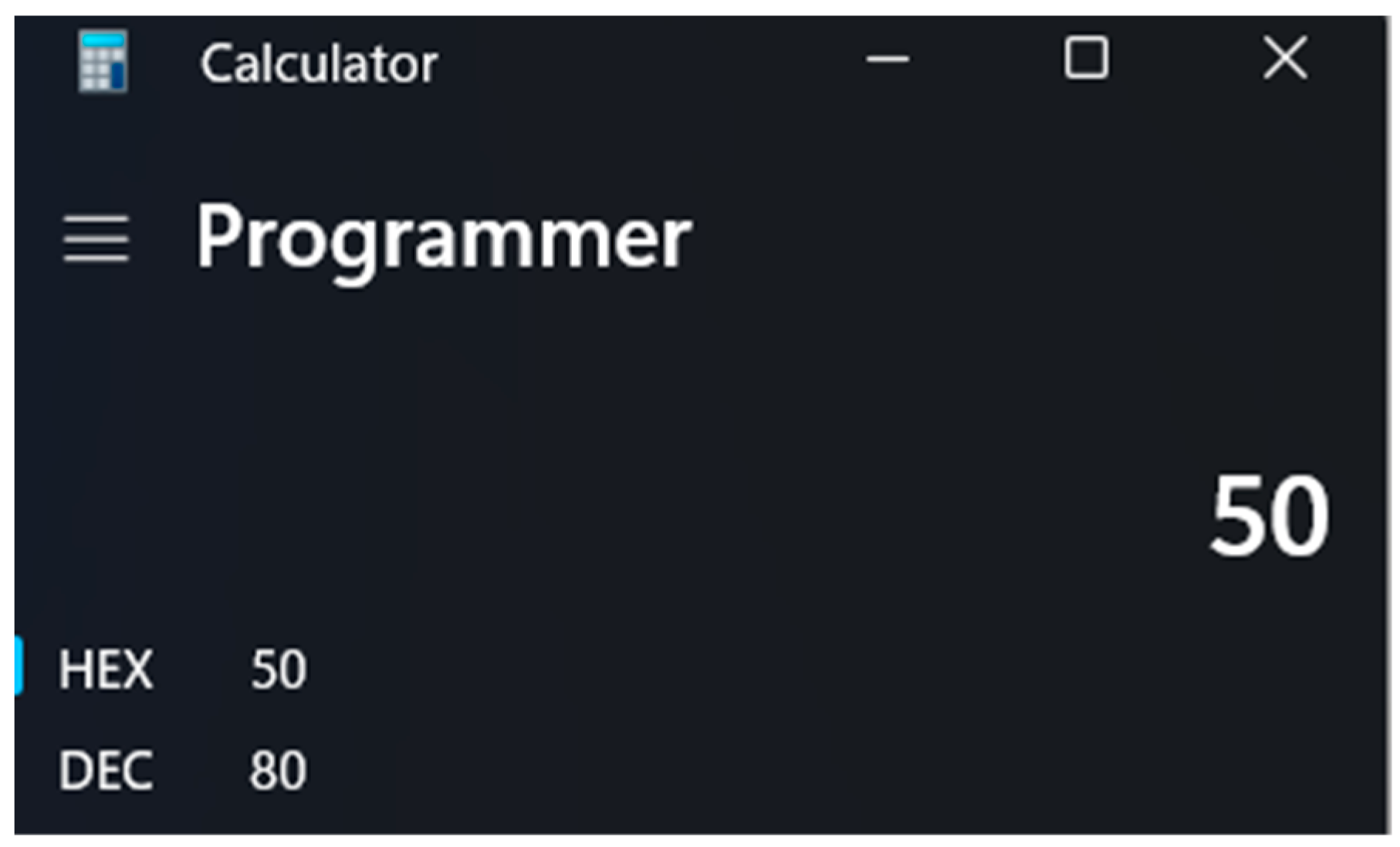
3.3. Conversion of Hexadecimal (HEX) Values from PCAN-View Software to Decimal (DEC)
4. Discussion
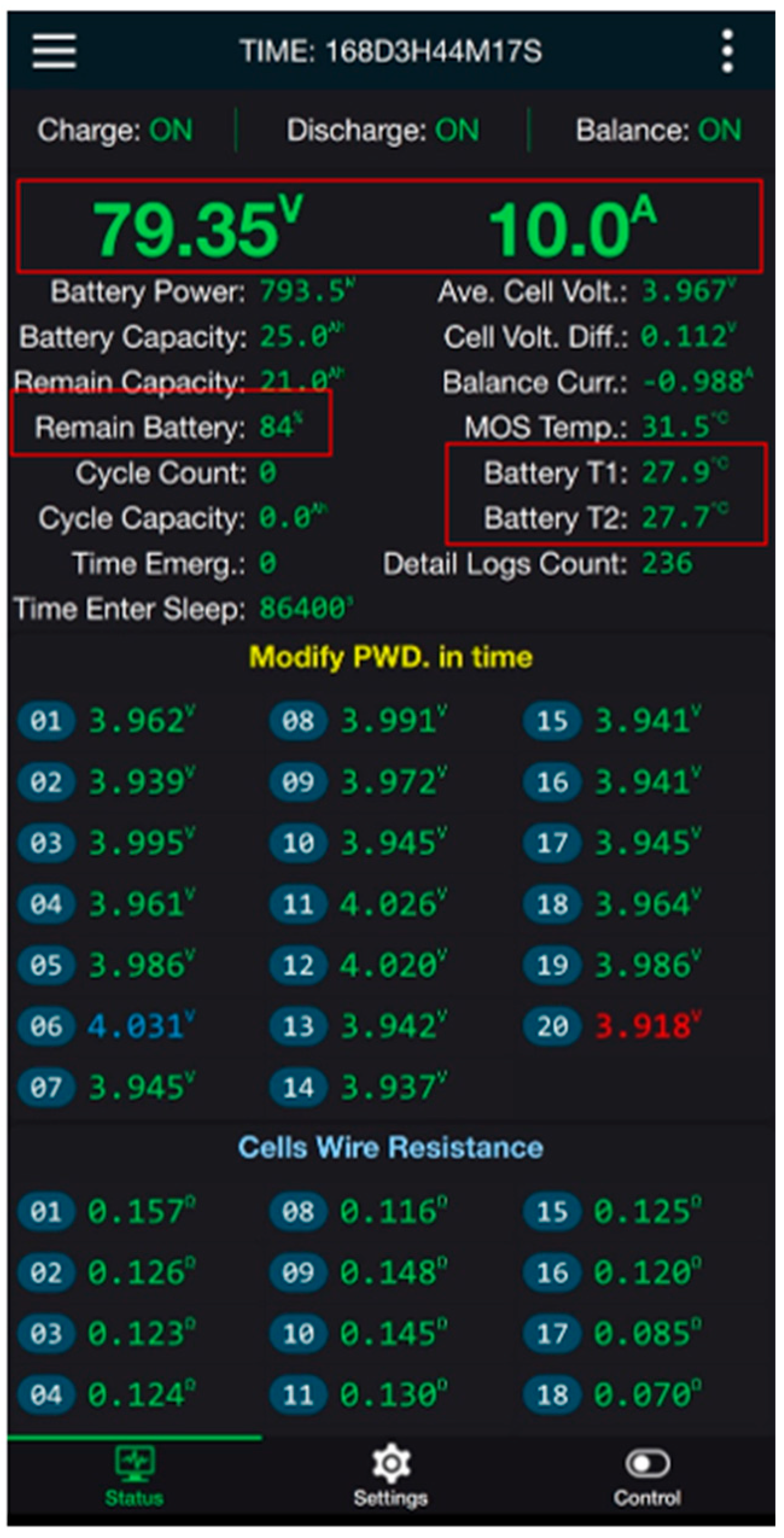
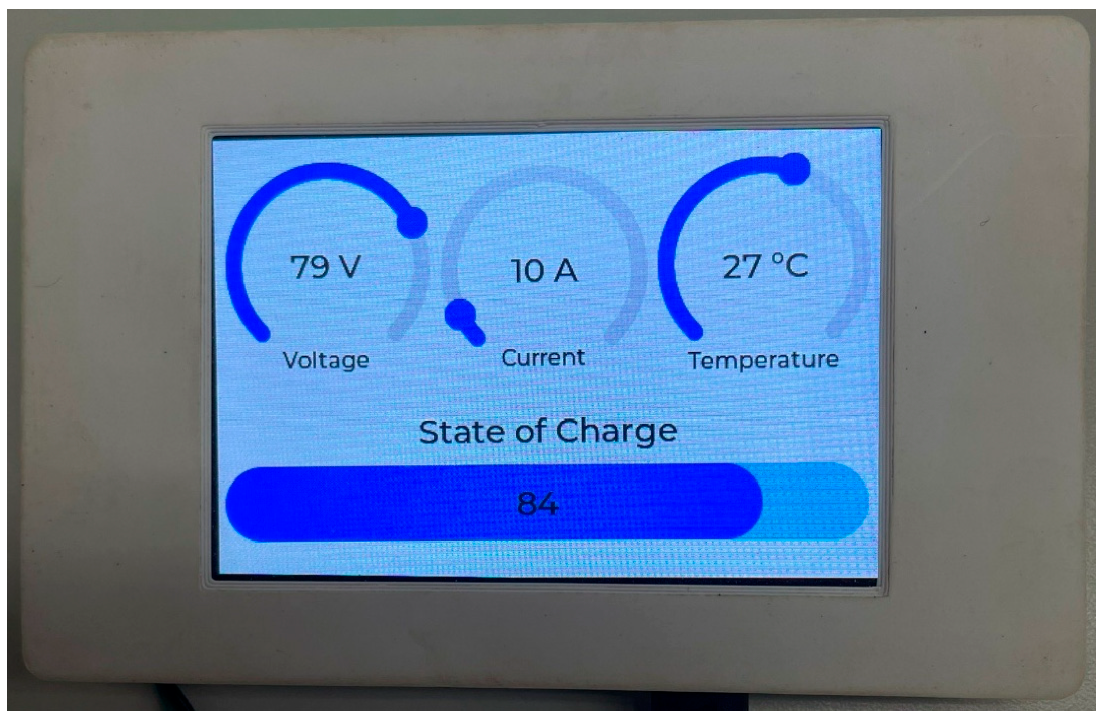
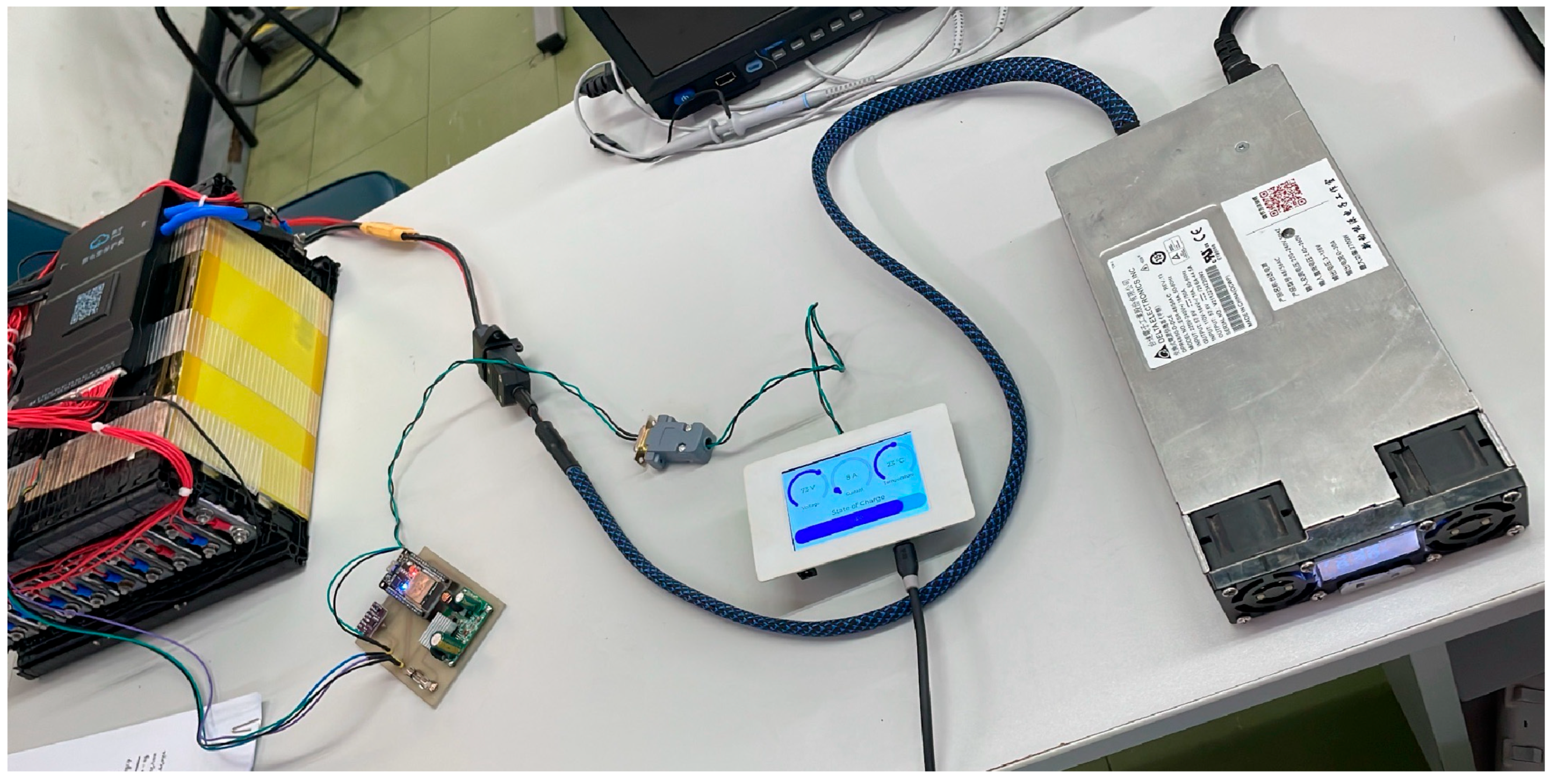
4.1. Data Communication Test Results via CAN Bus
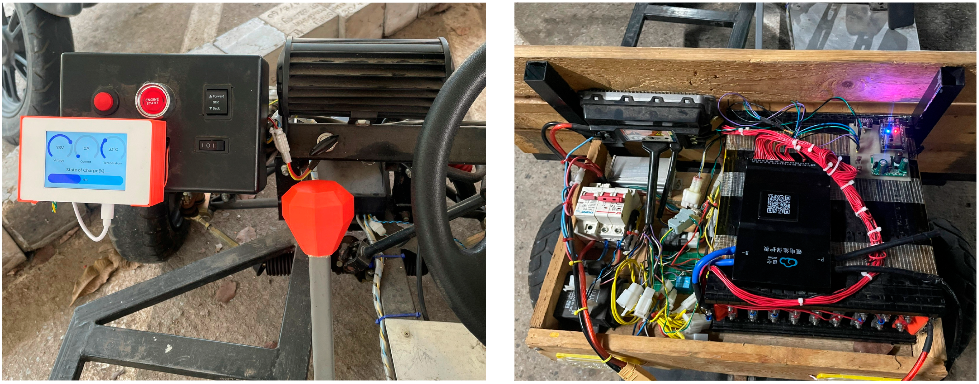
4.2. Results Analysis and System Performance Evaluation
- Real-time data acquisition from the BMS.
- Clear and accurate display corresponding to the actual system values.
- Scalability for integration with other control systems via the CAN bus.
- Potential for signal stability issues over extended CAN bus cable lengths.
- The physical layout and arrangement of components may require further optimization in specific areas to mitigate potential signal interference.
4.3. Limitations and Mathematical Modeling
4.4. Real-World Applications
4.5. Future Work and Research Directions
5. Conclusions
Author Contributions
Funding
Data Availability Statement
Acknowledgments
Conflicts of Interest
References
- Lipu, M.S.H.; Al Mamun, A.; Ansari, S.; Miah, S.; Hasan, K.; Meraj, S.T.; Abdolrasol, M.G.M.; Rahman, T.; Maruf, H.; Sarker, M.R.; et al. Battery Management, Key Technologies, Methods, Issues, and Future Trends of Electric Vehicles: A Pathway toward Achieving Sustainable Development Goals. Batteries 2022, 8, 119. [Google Scholar] [CrossRef]
- Haghani, M.; Sprei, F.; Kazemzadeh, K.; Shahhoseini, Z.; Aghaei, J. Trends in electric vehicles research. Transp. Res. Part D Transp. Environ. 2023, 123, 103881. [Google Scholar] [CrossRef]
- Ghazali, A.K.; Aziz, N.A.A.; Hassan, M.K. Advanced Algorithms in Battery Management Systems for Electric Vehicles: A Comprehensive Review. Symmetry 2025, 17, 321. [Google Scholar] [CrossRef]
- Uzair, M.; Abbas, G.; Hosain, S. Characteristics of Battery Management Systems of Electric Vehicles with Consideration of the Active and Passive Cell Balancing Process. World Electr. Veh. J. 2021, 12, 120. [Google Scholar] [CrossRef]
- Castillo-Martínez, D.H.; Rodríguez-Rodríguez, A.J.; Soto, A.; Berrueta, A.; Vargas-Requena, D.T.; Matias, I.R.; Sanchis, P.; Ursúa, A.; Rodríguez-Rodríguez, W.E. Design and On-Field Validation of an Embedded System for Monitoring Second-Life Electric Vehicle Lithium-Ion Batteries. Sensors 2022, 22, 6376. [Google Scholar] [CrossRef]
- Alzahrani, A.; Wangikar, S.M.; Indragandhi, V.; Singh, R.R.; Subramaniyaswamy, V. Design and Implementation of SAE J1939 and Modbus Communication Protocols for Electric Vehicle. Machines 2023, 11, 201. [Google Scholar] [CrossRef]
- Nichols, K.M.; Roembke, R.A.; Adamczyk, P.G. Real-Time Motor Control Using a Raspberry Pi, ROS, and CANopen over EtherCAT, with Application to a Semi-Active Prosthetic Ankle. Actuators 2025, 14, 84. [Google Scholar] [CrossRef]
- Bui, V.-T.; Dow, C.-R.; Huang, Y.-C.; Liu, P.; Thai, V.D. A Canopen-Based Gateway and Energy Monitoring System for Electric Bicycles. Energies 2020, 13, 3766. [Google Scholar] [CrossRef]
- Choi, M.; Lee, M.; Im, H.; Lee, J.; Lee, S. Shallow Learning-Based Intrusion Detection System for In-Vehicle Network: ASIC Implementation. Electronics 2025, 14, 683. [Google Scholar] [CrossRef]
- He, W.; Baig, M.J.A.; Iqbal, M.T. An Open-Source Supervisory Control and Data Acquisition Architecture for Photovoltaic System Monitoring Using ESP32, Banana Pi M4, and Node-RED. Energies 2024, 17, 2295. [Google Scholar] [CrossRef]
- Salgado, M.; Garcia, P.; Integration of a CANopen Protocol Stack in an Embedded Application Employing the CANFestival Stack. ResearchGate. 2016. Available online: https://www.researchgate.net/publication/309827484_Integration_of_a_CANopen_Protocol_Stack_in_an_Embedded_Application_Employing_the_CANFestival_Stack (accessed on 20 September 2024).
- Artronshop. ATD3.5-S3 Board: ESP32-S3 with 3.5” Capacitive Touchscreen Display. Available online: https://www.artronshop.co.th/product/567 (accessed on 20 April 2025).
- Hercog, D.; Lerher, T.; Truntič, M.; Težak, O. Design and Implementation of ESP32-Based IoT Devices. Sensors 2023, 23, 6739. [Google Scholar] [CrossRef] [PubMed]
- Syssi. ESPHome Component for JK-BMS. GitHub. Available online: https://github.com/syssi/esphome-jk-bms (accessed on 20 September 2024).
- Rimpas, D.; Orfanos, V.A.; Chalkiadakis, P.; Christakis, I. Design and Development of a Low-Cost and Compact Real-Time Monitoring Tool for Battery Life Calculation. Eng. Proc. 2023, 58, 17. [Google Scholar] [CrossRef]
- Ehsani, M.; Gao, Y.; Emadi, A. Modern Electric, Hybrid Electric, and Fuel Cell Vehicles, 2nd, ed.; CRC Press: Boca Raton, FL, USA, 2017. [Google Scholar] [CrossRef]
- Plett, G.L. Extended Kalman filtering for battery management systems of LiPB-based HEV battery packs: Part 3. State and parameter estimation. J. Power Sources 2004, 134, 277–292. [Google Scholar] [CrossRef]
- Xie, Y.; Zeng, G.; Chen, Y.; Kurachi, R.; Takada, H.; Li, R. Worst Case Response Time Analysis for Messages in Controller Area Network with Gateway. IEICE Trans. Inf. Syst. 2013, E96.D, 1467–1477. [Google Scholar] [CrossRef]
- Pooyandeh, M.; Sohn, I. Smart Lithium-Ion Battery Monitoring in Electric Vehicles: An AI-Empowered Digital Twin Approach. Mathematics 2023, 11, 4865. [Google Scholar] [CrossRef]
- Sureshkumar, M.S.; Rahul, R.; Joshika, S.; Suraj, S. Internet-of-Things-Based Smart Home Energy Management System with Multi-Sensor Data Fusion. Eng. Proc. 2024, 66, 10. [Google Scholar] [CrossRef]
- Hafeez, A.; Malik, H.; Avatefipour, O.; Rongali, P.R.; Zehra, S. Comparative Study of CAN-Bus and FlexRay Protocols for In-Vehicle Communication. SAE Tech. Pap. 2017, 1, 17. [Google Scholar] [CrossRef]
- Xing, J.; Wu, P. State of Charge Estimation of Lithium-Ion Battery Based on Improved Adaptive Unscented Kalman Filter. Sustainability 2021, 13, 5046. [Google Scholar] [CrossRef]
- PEAK-System. PCAN-USB Product Image and Technical Specifications. Available online: https://www.peak-system.com/PCAN-USB.199.0.html?L=1 (accessed on 20 April 2025).
- Assi, M.; Amer, M. A Comparative Analysis of Lithium-Ion Batteries Using a Proposed Electrothermal Model Based on Numerical Simulation. World Electr. Veh. J. 2025, 16, 60. [Google Scholar] [CrossRef]
- Galvão, J.R.; Calligaris, L.B.; de Souza, K.M.; Gotz, J.D.; Junior, P.B.; Corrêa, F.C. Hybrid Equalization Topology for Battery Management Systems Applied to an Electric Vehicle Model. Batteries 2022, 8, 178. [Google Scholar] [CrossRef]
- Sornek, K.; Augustyn-Nadzieja, J.; Rosikoń, I.; Łopusiewicz, R.; Łopusiewicz, M. Status and Development Prospects of Solar-Powered Unmanned Aerial Vehicles—A Literature Review. Energies 2025, 18, 1924. [Google Scholar] [CrossRef]
- Nazaralizadeh, S.; Banerjee, P.; Srivastava, A.K.; Famouri, P. Battery Energy Storage Systems: A Review of Energy Management Systems and Health Metrics. Energies 2024, 17, 1250. [Google Scholar] [CrossRef]
- Jimenez-Martinez, M.; Valencia-Sánchez, J.L.; Torres-Cedillo, S.G.; Cortés-Pérez, J. Battery Housing for Electric Vehicles, a Durability Assessment Review. Designs 2024, 8, 113. [Google Scholar] [CrossRef]
- Yao, L.; Xu, S.; Tang, A.; Zhou, F.; Hou, J.; Xiao, Y.; Fu, Z. A Review of Lithium-Ion Battery State of Health Estimation and Prediction Methods. World Electr. Veh. J. 2021, 12, 113. [Google Scholar] [CrossRef]
- Jikong BMS. JKBMS B2A24S20P 7S–24S Active Balance BMS—Product Specifications and Images. Available online: https://jikongbms.com/product/jkbms-b2a24s20p-7s-24s-active-balance-bms-balance-current-2a-continuous-current-200a-lifepo4-li-ion-lto-battery/ (accessed on 20 April 2025).
- NXP Semiconductors. TJA1051T High-Speed, Low-Power CAN Transceiver. Available online: https://www.nxp.com/products/automotive/can-and-automation/can-transceivers/tja1051-high-speed-low-power-can-transceiver:TJA1051T (accessed on 20 April 2025).
- Kalamaras, S.D.; Tsitsimpikou, M.-A.; Tzenos, C.A.; Lithourgidis, A.A.; Pitsikoglou, D.S.; Kotsopoulos, T.A. A Low-Cost IoT System Based on the ESP32 Microcontroller for Efficient Monitoring of a Pilot Anaerobic Biogas Reactor. Appl. Sci. 2025, 15, 34. [Google Scholar] [CrossRef]
- Artronshop. ATD3.5-S3 CAN Bus Shield: CAN Bus Expansion Module for ATD3.5-S. Available online: https://www.artronshop.co.th/product/585 (accessed on 20 April 2025).
- Espressif Systems. Development Boards and Kits Overview. Available online: https://www.espressif.com/en/products/devkits (accessed on 20 April 2025).
- Bu, Q.; Zhang, S.; Ma, N.; Luo, Q.; Sun, B. Research on Energy Management Method of Fuel Cell/Supercapacitor Hybrid Trams Based on Optimal Hydrogen Consumption. Sustainability 2023, 15, 11234. [Google Scholar] [CrossRef]
- Zhu, T.; Min, H.; Yu, Y.; Zhao, Z.; Xu, T.; Chen, Y.; Li, X.; Zhang, C. An Optimized Energy Management Strategy for Preheating Vehicle-Mounted Li-ion Batteries at Subzero Temperatures. Energies 2017, 10, 243. [Google Scholar] [CrossRef]
- Valero-Mora, P.M.; Stevens, A. Human-centred design and assessment of information technologies in traffic. IET Intell. Transp. Syst. 2013, 7, 171–173. [Google Scholar] [CrossRef]


| Pin | Connection Type |
|---|---|
| 1 | Not connected/optional + 5 V |
| 2 | CAN-L |
| 3 | GND |
| 6 | GND |
| 7 | CAN-H |
| 9 | Not connected/optional + 5 V |
| Number | Name |
|---|---|
| 1 | ESP32 Microcontroller |
| 2 | Buck Converter |
| 3 | TJA1051 CAN Transceiver |
| 4 | Fuse |
| 5 | CAN Bus Communication Port |
| 6 | Battery Management System (BMS) Communication Port |
| Byte Number | Parameter Name | Value/Unit |
|---|---|---|
| 0 | State of Charge | 1% |
| 1 |
| Byte Number | Parameter Name | Value/Unit |
|---|---|---|
| 0 | Battery Terminal Voltage | 1 V |
| 1 | ||
| 2 | Total Pack Current | 1 A |
| 3 | ||
| 4 | Battery Temperature | 1 °C |
| 5 |
| CAN ID | Byte | Raw Value (HEX) | Converted Value (DEC) | Parameter/Meaning | Value in JK BMS App |
|---|---|---|---|---|---|
| 0x355 | 0–1 | 0x0054 | 84 | SOC (%) | 84% |
| 0x356 | 0–1 | 0x004F | 79 | Battery Voltage (V) | 79 V |
| 0x356 | 2–3 | 0x000A | 10 | Total Pack Current (A) | 10 A |
| 0x356 | 4–5 | 0x001B | 27 | Battery Temperature (°C) | 27 °C |
Disclaimer/Publisher’s Note: The statements, opinions and data contained in all publications are solely those of the individual author(s) and contributor(s) and not of MDPI and/or the editor(s). MDPI and/or the editor(s) disclaim responsibility for any injury to people or property resulting from any ideas, methods, instructions or products referred to in the content. |
© 2025 by the authors. Published by MDPI on behalf of the World Electric Vehicle Association. Licensee MDPI, Basel, Switzerland. This article is an open access article distributed under the terms and conditions of the Creative Commons Attribution (CC BY) license (https://creativecommons.org/licenses/by/4.0/).
Share and Cite
Yanpreechaset, C.; Donjaroennon, N.; Nuchkum, S.; Leeton, U. Development of an EV Battery Management Display with CANopen Communication. World Electr. Veh. J. 2025, 16, 375. https://doi.org/10.3390/wevj16070375
Yanpreechaset C, Donjaroennon N, Nuchkum S, Leeton U. Development of an EV Battery Management Display with CANopen Communication. World Electric Vehicle Journal. 2025; 16(7):375. https://doi.org/10.3390/wevj16070375
Chicago/Turabian StyleYanpreechaset, Chanon, Natthapon Donjaroennon, Suphatchakan Nuchkum, and Uthen Leeton. 2025. "Development of an EV Battery Management Display with CANopen Communication" World Electric Vehicle Journal 16, no. 7: 375. https://doi.org/10.3390/wevj16070375
APA StyleYanpreechaset, C., Donjaroennon, N., Nuchkum, S., & Leeton, U. (2025). Development of an EV Battery Management Display with CANopen Communication. World Electric Vehicle Journal, 16(7), 375. https://doi.org/10.3390/wevj16070375