Abstract
Brushless DC motors are often used as traction motors in electric vehicles due to their high power density and efficiency. The dc-link electrolytic capacitor is the most vulnerable part of the brushless DC motor drive system, and it determines the reliability of the motor drive system. Therefore, it is of great importance to monitor the life of the dc-link electrolytic capacitor in the drive system. To carry out the lifetime monitoring of capacitors, a dc-link series switch circuit composed of diodes and power switching devices is introduced to calculate the capacitance value. The lifetime of the capacitor is then monitored in real time through this capacitance value. During normal steady-state operation of the motor, the control strategy of the inverter is switched. When the dc-link switch is turned off, the charging vector is used to charge the dc-link capacitor. Due to the presence of the diode and the dc-link switch, the energy charged to the dc-link by the motor can only flow into the capacitor and cannot be released immediately. Therefore, the capacitance value is calculated through the change in capacitor voltage and the capacitor current reconstructed from the three-phase currents of the motor. The feasibility of the method proposed in this paper is experimentally verified by building a brushless DC motor system.
1. Introduction
The brushless DC motor (BLDCM), with its advantages of high efficiency and high power density, has been widely used in the fields of electric vehicles (EVs) and industrial equipment [1,2,3]. The equivalent circuit diagram of the BLDCM system is shown in Figure 1. The BLDCM system mainly consists of four parts: a DC power supply, the dc-link, a three-phase inverter, and the BLDCM itself. The motor drive system composed of the dc-link and the three-phase inverter, as an important part of the BLDCM system, generally consists of dc-link capacitors and power switching devices. Due to the high cost–performance ratio of electrolytic capacitors (their significant cost-per-unit-capacity advantage and moderate volume power density), the dc-link capacitors in the motor drive system usually use electrolytic capacitors to buffer energy and filter and stabilize voltage.
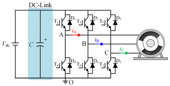
Figure 1.
Equivalent circuit of BLDCM system.
However, according to recent research [4,5,6], it is known that in harsh working environments and with an increasing usage time, the use of dc-link electrolytic capacitors can bring reliability issues to motor drive systems. Electrolytic capacitors are the most vulnerable components in motor drive systems. Therefore, effective monitoring of the life of dc-link electrolytic capacitors in motor drive systems is essential for the predictive maintenance of motor drive systems.
Regarding the dc-link capacitors in power electronic converters, existing articles have systematically summarized and classified their monitoring methods [7,8,9], which can generally be divided into offline methods, quasi-online methods, and real online methods. Although offline methods offer high monitoring accuracy, their application is limited due to the need to remove the capacitor from the system [10] or use additional measuring devices [11]. In contrast, quasi-online and online methods, which do not alter the normal state of the dc-link capacitor, have been widely applied in recent years.
The quasi-online method can generally be divided into two categories: one category utilizes the specific operating conditions of the system where the monitored capacitor is located to monitor the lifetime of capacitor [12,13,14,15,16,17,18,19]; the other category involves artificially creating special operating conditions for the system where the monitored capacitor is located for capacitor monitoring [20,21,22]. In articles [12,13], the dc-link capacitors of electric vehicles are taken as the monitoring objects, and corresponding capacitor lifetime monitoring methods are proposed. In article [12], capacitor monitoring is implemented by utilizing the condition where the dc-link capacitor discharges to the traction motor when the drive system of the electric vehicle is turned on or off. In article [13], to reduce the impact of electric vehicle operation on capacitor monitoring, the discharge curve of the dc-link capacitor to the motor windings after the electric vehicle has stopped is used to monitor the capacitor. In articles [14,15,16,17,18], some special operating conditions of trains are utilized to achieve capacitor monitoring. In article [14], capacitor monitoring is achieved by utilizing the condition where two dc-link capacitors discharge to the braking resistor after the main braking circuit opens during train operation. In article [15], voltage fluctuations on the dc-link during actual train operation are leveraged to calculate capacitance. By employing changes in the capacitor voltage and reconstructed capacitor current, this approach monitors capacitor lifetime. In articles [16,17,18], capacitor lifetime monitoring is implemented by utilizing the pre-charging process of the dc-link capacitor prior to train operation. In article [16], to address the drawbacks of high voltage sensor noise and low sampling rates in trains, an equivalent circuit for train pre-charging is first constructed based on the dc-link topology of trains. Capacitance is then calculated using an improved recursive extended least squares method applied to this circuit. In articles [17,18], based on the pre-charging model of a train, a three-stage iterative algorithm and the maximum likelihood method with Newton–Raphson iteration are respectively employed to estimate capacitor aging parameters. In article [19], the dc-link capacitor in solar inverters is targeted for monitoring. During the night when the solar inverter is not in operation, the inverter is modulated into an active power converter through a controller, and then low-order harmonic currents are injected into the grid side. The capacitance C and equivalent series resistance of the capacitor are then calculated.
The aforementioned studies focus on the first type of quasi-online method, while articles [20,21,22] focus on the second type of quasi-online method, that is, creating conditions that facilitate capacitor monitoring for the purpose of lifespan monitoring. In article [20], the load is artificially disconnected during normal converter operation, inducing a controlled rise in dc-link capacitor voltage to create optimal conditions for capacitor monitoring. In article [21], a charging vector is intermittently introduced during normal converter operation to charge the dc-link capacitor, inducing controlled voltage rise across the capacitor. The capacitance of the capacitor is then calculated using the change in capacitor voltage and the capacitor current. In article [22], capacitance is calculated using physical quantities, namely the output voltage and current of the rectifier, during the unloaded conditions of the load connected to the power factor correction converter. This method can be implemented in both continuous conduction mode and discontinuous conduction mode of the power factor correction converter.
The quasi-online method mentioned above can achieve high-precision capacitor monitoring. The first type of quasi-online method relies on the special operating conditions of the system where the capacitor to be monitored is located. The second type of quasi-online method requires the artificial creation of suitable operating conditions for capacitor monitoring, thereby introducing potential risks to the operation of the motor. The real-time online method can be implemented during the normal operation of the system where the capacitor to be monitored is located. In article [23], an ESR monitoring method is proposed, but the measurement of the root mean square requires the design of additional integrated circuits. In article [24], AC voltage components are injected into the dc-link to calculate the capacitance online through the power of the capacitor. However, voltage injection introduces additional risks to the operation of the motor. In article [25], a dc-link current sensor is used to obtain the capacitor current. The average capacitor power calculated from the current and voltage is used to estimate the ESR online, which requires an additional current sensor.
This paper utilizes a topology with a series switch on the dc-link. During the normal electric operation of the BLDCM, different control strategies are switched to charge the dc-link electrolytic capacitor. Since energy will only flow unidirectionally into the dc-link capacitor and can be stored in it, there will be no situation where the capacitor voltage exceeds the DC power supply voltage and the capacitor discharges immediately. In order to minimize the random errors of the three-phase current and duty cycle as much as possible, the capacitor monitoring window is fixed during the steady-state operation of the motor. Finally, the capacitance C of the dc-link electrolytic capacitor is calculated using the change in capacitor voltage and the capacitor current reconstructed from the three-phase currents of the motor, thereby achieving the purpose of monitoring the lifetime of the capacitor.
The rest of this paper is organized as follows: Section 2 introduces the equivalent model and aging characteristics of the monitoring object of this paper, namely the electrolytic capacitor. Section 3 introduces the topology introduced for capacitor monitoring and then elaborates on the operating mode of the BLDCM system with series-connected switches on the dc-link. Section 4 proposes a method for monitoring the life of the dc-link capacitor and designs a controller. Section 5 first introduces the hardware implementation of the experimental system and then fully demonstrates the feasibility and effectiveness of the capacitor monitoring method from three perspectives through experimental results and analysis. Section 6 concludes the paper.
2. Equivalent Model and Aging Characteristics of Electrolytic Capacitors
In order to conduct a detailed analysis of electrolytic capacitors, it is necessary to perform physical modeling of the simplified equivalent circuit of electrolytic capacitors. Figure 2 presents the widely used simplified equivalent model of electrolytic capacitors and their impedance characteristics. The simplified equivalent model of electrolytic capacitors consists of three parts: the equivalent series capacitance (ESC, hereinafter referred to as capacitance (C), the equivalent series resistance (ESR), and the equivalent series inductance (ESL). Since electrolytic capacitors on the dc-link are commonly used in power electronic converters, the value of ESL is relatively small and can generally be neglected.

Figure 2.
Equivalent model of electrolytic capacitor.
There are many factors that cause the aging and failure of electrolytic capacitors, such as mechanical stress, thermal stress, voltage stress, excessive current fluctuations, the humidity of the environment in which the electrolytic capacitors are located, and the level of manufacturing [26]. It has been reported that the evaporation of the electrolyte and chemical reactions within electrolytic capacitors are the main intrinsic causes of their failure. Their service life is primarily determined by the ambient temperature in which the electrolytic capacitors are placed. According to the Arrhenius 10-degree rule, for every 10 °C increase in the ambient temperature of the electrolytic capacitors, their service life will be shortened by about 50% [27,28].
During the aging process of electrolytic capacitors, the evaporation of the internal electrolyte and the continuous electrochemical reactions cause the ESR of the electrolytic capacitors to increase continuously. At the same time, the evaporation of the electrolyte leads to a continuous reduction in the contact area between the metal electrodes and the electrolyte, resulting in a continuous decrease in the capacitance value C. Generally, an electrolytic capacitor is considered to have failed and needs to be replaced in a timely manner when its ESR doubles or its capacitance drops by 20% of the initial capacitance value [29]. This is to prevent more serious consequences. In this paper, the capacitance C of the electrolytic capacitor is used as the monitored aging parameter. The aging and failure of the capacitor are determined by calculating the capacitance C in real time.
3. Operation Mode of BLDCM Systems with DC-Link Series Switches
Since this paper uses the charging curve of the dc-link capacitor to calculate its capacitance, thereby monitoring the lifetime of the electrolytic capacitor, the motor can charge the dc-link capacitor through the application of different control vectors by the inverter. However, to obtain the charging curve of the dc-link capacitor, it is necessary to ensure that during the capacitor charging period, the energy fed back from the motor to the dc-link can only flow into the capacitor and the capacitor does not accept any other energy. Moreover, the energy flowing into the capacitor should not be released immediately. Therefore, the diode D and the dc-link switch T7 shown in Figure 3 are introduced, which allows the charging curve of the dc-link capacitor to be obtained and thus facilitates capacitor monitoring.
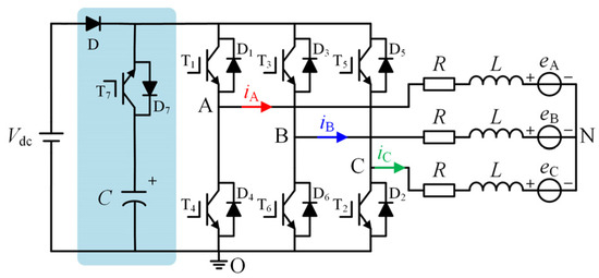
Figure 3.
The equivalent circuit of a brushless DC motor system with series capacitors in the switching tube.
The equivalent circuit of the BLDCM system with a series switch on the dc-link is shown in Figure 3. It mainly consists of four parts: the DC power supply Vdc, the series switch circuit on the dc-link, the three-phase inverter, and the BLDCM. The series switch circuit on the dc-link, as indicated by the blue shaded area, is composed of three parts: the dc-link diode D, the power switch T7, and the electrolytic capacitor C. Power switches T1–T7 in Figure 3 are Insulated Gate Bipolar Transistors (IGBTs), and D1–D7 are the antiparallel freewheeling diodes for power switches T1–T7.
Assuming that the three-phase stator windings of the BLDCM are symmetrical, the terminal voltage equations can be expressed as
where L and R are the equivalent phase inductance and equivalent phase resistance of the BLDCM, respectively. N is the neutral point of the motor. eA, eB, and eC are the phase electromotive forces (EMFs), namely the A, B, and C phases of the motor, respectively. iA, iB, and iC are the three-phase currents of the motor. The positive directions of the three-phase currents are indicated by the arrows in Figure 3.
To obtain the maximum driving torque, the BLDCM generally adopts a three-phase six-step control mode with two-phase conduction. The position information is obtained using Hall position sensors, and commutation is performed at every 60° electrical angle. Figure 4 shows the ideal back-electromotive force (EMF), ideal three-phase currents, corresponding Hall signals, and the sector positions of the motor for different conduction sectors. Here, θ represents the electrical angle of the motor. As can be seen from the figure, the motor is divided into six conduction sectors within a 360° electrical cycle. Therefore, in each conduction cycle, two phases are always in the conduction state, and one phase is in the floating state. Taking the A + B− conduction sector as an example for analysis, at this time, phase A and phase B are the conduction phases, which are the positive conduction phase and the negative conduction phase, respectively, and phase C is the floating phase.
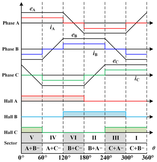
Figure 4.
The ideal back-EMFs, ideal three-phase current, and Hall signal correspondence diagram for the brushless DC motor.
Since the phase current of the motor is approximately constant during a conduction cycle, the voltage drop across the inductor is close to 0 and can be neglected. Assume that the motor is operating in the P + N− conduction sector at this moment. Therefore, from Equation (1), the line-to-line voltage UPN of the motor during conduction can be obtained as
where I = iP = −iN, E = eP = −eN, ke is the back-emf coefficient, and ω is the motor speed.
Considering the five common PWM modulation methods for BLDCM electric operation, there are three types of vectors applied to the six switches of the inverter: effective vector Ve, zero vector Vzx (x = 0, 1), and charging vector Vc. The equivalent circuit current paths corresponding to the three types of vectors in the inverter are shown in Figure 5. When the effective vector Ve is applied, the upper-bridge switch of the positive conduction phase and the lower-bridge switch of the negative conduction phase are turned on, as shown in Figure 5a. When the zero vector Vzx (x = 0, 1) is applied, either the upper-bridge switch of the positive conduction phase or the lower-bridge switch of the negative conduction phase is turned on, with the current paths shown in Figure 5b and Figure 5c, respectively. When the charging vector Vc is applied, all six switches of the three-phase inverter are turned off, as shown in Figure 5d.


Figure 5.
The current flow path diagram under different control vectors. (a) When the effective vector Ve is in effect. (b) When the zero vector Vz0 is in effect. (c) When the zero vector Vz1 is in effect. (d) When the charging vector Vc is in effect.
In the BLDCM system with a series switch on the dc-link, the DC power supply first charges the electrolytic capacitor through diodes D and D7. When the capacitor voltage ucap reaches the DC power supply voltage udc, ignoring the voltage drop across the diodes, the capacitor voltage will not be less than the DC power supply voltage udc. In this case, when the charging vector Vc is applied to the three-phase inverter, a situation may occur where the motor energy charges the dc-link, as shown in the equivalent circuit path diagram in Figure 5d. Due to the presence of the diode D in the series switch circuit on the dc-link, the energy fed back to the dc-link can only flow unidirectionally to the electrolytic capacitor C. Moreover, the turn-off of the dc-link IGBT allows the electrolytic capacitor to accept energy from the motor without immediate release, thereby causing an increase in the capacitor voltage.
Therefore, there are two equivalent circuits on the dc-link, as shown in Figure 6. In Figure 6a, the charging vector Vc is not used, and the DC power supply Vdc provides energy to the motor. As the charging vector Vc continuously charges the dc-link capacitor, the turn-on of the switch T7 will result in the equivalent circuit on the dc-link, as shown in Figure 6b, that is, the electrolytic capacitor provides energy to the motor until the capacitor voltage drops to the level of the DC power supply voltage.
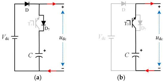
Figure 6.
DC-link equivalent circuit diagram. (a) When dc-link switch T7 is turned off, and (b) when dc-link switch T7 is turned on.
As can be seen in the above figure, by reasonably arranging the vector control strategy and the on–off switch of the dc-link switch T7, the increase and decrease in the dc-link electrolytic capacitor voltage can be achieved. This provides the prerequisite for calculating the capacitance C of the electrolytic capacitor and thus achieving the purpose of monitoring the lifetime of the capacitor.
4. Proposed Strategy
4.1. Capacitance Calculation Methods
Depending on whether the BLDCM drive system needs to perform capacitor monitoring, the control strategy of the motor is divided into two types: a normal operation state and a capacitor monitoring state.
When the motor is in the normal operation state, the dc-link switch T7 is kept on, and the DC power supply Vdc provides energy to the motor. The inverter is controlled using the two zero vectors Vzx, as shown in Figure 5a–c. Let the duty cycle of the effective vector Ve be d1, and the duty cycle of the zero vector Vzx is 1 − d1. The average input line voltage UPN can be expressed as follows:
where Udc is the average voltage of the DC power supply. The effective vector duty cycle d1 during the normal electric operation of the motor can be obtained from Equation (3) as follows:
When the motor drive system is in the capacitor monitoring state, the dc-link is divided into boost mode and buck mode. In boost mode, the dc-link switch T7 is first turned off, and the dc-link capacitor voltage increases. When it reaches a certain value, it enters buck mode, where the dc-link switch T7 is turned on. At this time, the electrolytic capacitor voltage is greater than the DC power supply voltage, and the electrolytic capacitor provides energy to the motor, causing the dc- link capacitor voltage to decrease. This cycle is repeated.
(1) Boost Mode: In this mode, the inverter is controlled using the two control vectors, the effective vector Ve and the charging vector Vc, as shown in Figure 5a,d. Let the duty cycle of the effective vector Ve be d2, and the duty cycle of the charging vector Vc is 1 − d2. Thus, the average input line-to-neutral voltage UPN of the motor can be obtained as follows:
where Ucap is the average capacitor voltage during each control cycle in the boost period. Using Equation (5), the effective vector duty cycle d2 of the motor in boost mode can be obtained:
(2) Buck Mode: In this mode, the inverter is controlled using the two control vectors, the effective vector Ve and the zero vector Vzx, as shown in Figure 5a–c. At this time, the dc-link electrolytic capacitor provides energy to the motor, as shown in Figure 6b. Let the duty cycle of the effective vector Ve in a control period be d3, and the duty cycle of the zero vector Vzx is 1 − d3. Thus, the average input line voltage UPN of the motor can be obtained as follows:
where Ucap is the average capacitor voltage during each control cycle in the buck period. Using Equation (7), the effective vector duty cycle d3 of the motor in boost mode can be obtained:
Since the average input line-to-neutral voltage Upn of the motor in Equations (3), (5) and (7) is between 0 and Udc, the normal speed regulation of the motor is ensured.
According to the law of Ohm, the capacitance C of the capacitor can be obtained from the charging current icap of the capacitor and the capacitor voltage ucap, as shown in the following equation:
where t2 − t1 is an estimated interval for capacitor monitoring, that is, a charging cycle included in the capacitor monitoring period. ucap(t2) − ucap(t1) is the change in capacitor voltage during the estimated interval. Since the capacitor current is always positive during charging, Equation (9) can rewrite the current integral as follows:
where ic_ave is the average charging current of the capacitor during the estimated interval. Combining the effective vector duty cycle d1 obtained from the controller, the average charging current of the capacitor ic_ave_Tci in the i-th control cycle can be solved as follows:
where iX_i (X = A, B, C) is the average value of the phase current of the motor in the conducting sector and is equal to the phase current of the motor since the method used in this paper is carried out under the steady-state condition of the motor. The values of S1, S2, and S3 in the equation are determined by the relationship between the three-phase currents of the motor and the capacitor charging current. Taking the B + C− conduction sector as an example for analysis, Figure 7 shows the charging current path of the motor in the B + C− conduction sector.
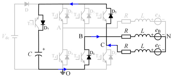
Figure 7.
The charging current path diagram of the motor in the B + C− conduction sector.
As shown in the figure above, when the motor operates within a specific conduction sector, the conduction phase of the three-phase windings in the motor remains constant throughout the charging vector activation period. At this time, the motor charges the dc-link electrolytic capacitor through the anti-parallel diode to form a new conduction path. The charging current is equal to the current of the positively conducting phase of the motor in the current sector. Therefore, the values of S1, S2, and S3 are as shown in Table 1.

Table 1.
S1, S2, and S3 values.
Assuming that an estimated interval t2 − t1 contains n control cycles in total, the average charging current ic_ave for the entire estimation window can be obtained as follows:
Substituting the above equation into Equation (10) yields the final formula for calculating the capacitance value, shown as follows:
In Equation (13), TC is a control period of the motor system.
From Equation (13), the capacitance calculation formula for the dc-link electrolytic capacitor can be obtained. The capacitance value of the electrolytic capacitor is calculated at the end of the charging phase. To further reduce the monitoring error, the arithmetic mean of 100 values is taken and then the capacitance value is output.
4.2. Controller Design Methods
The overall structure of the control block diagram of the method proposed in this paper is shown in Figure 8, which mainly consists of three parts: dual PI controllers, the control strategy switching and switch control module, and the capacitor monitoring module. Firstly, the three-phase currents of the motor are sensed by the current sensors. Then, the non-commutation current isel of the BLDCM is calculated in combination with the Hall signal from the Hall position sensor. At this time, the difference between the actual motor speed n, calculated from the Hall signal, and the reference speed n*, is input into the PI speed controller. Subsequently, the output of the PI speed controller and the non-commutation current isel are input into the PI current controller. Finally, according to the operating state of the motor, the duty cycle is output to control the inverter, thereby ensuring the stable operation of the motor.
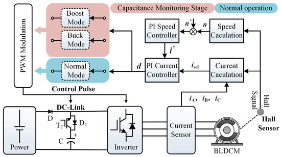
Figure 8.
The control block diagram of the proposed method.
The control strategy switching and switch control module mainly functions to switch the control strategy based on whether capacitor monitoring is needed and to generate the corresponding switch control signals. The motor control strategy is divided into two types based on whether capacitor monitoring is required, namely the capacitor monitoring state and the normal motor operation state. As mentioned above, when the motor does not need to monitor the dc-link electrolytic capacitor, the dc-link switch T7 remains in the on state, and the conventional PWM modulation method is used. When the dc-link electrolytic capacitor needs to be monitored, the controller issues a pulse signal to turn off the dc-link switch T7, switching to the modulation method for the capacitor monitoring state, which is described in detail above.
The capacitor monitoring module mainly includes the implementation method of capacitor monitoring. The flowchart of the capacitor monitoring method proposed in this paper is shown in Figure 9. When it is necessary to monitor the life of the dc-link electrolytic capacitor, the dc-link switch T7 is turned off, and the drive system switches to the boost control mode. The capacitor voltage increases. The capacitance value of the electrolytic capacitor is calculated based on the voltage change of the capacitor and the dc-link capacitor current reconstructed from the three-phase currents of the motor. The life of the capacitor is monitored through its capacitance value. After the voltage rises to a certain value, the dc-link switch T7 is turned on, and the drive system switches to the buck control mode. When the voltage drops to dc-link power supply voltage ucap, the drive system switches back to the boost mode. This cycle repeats, and the capacitance value is calculated once per cycle.
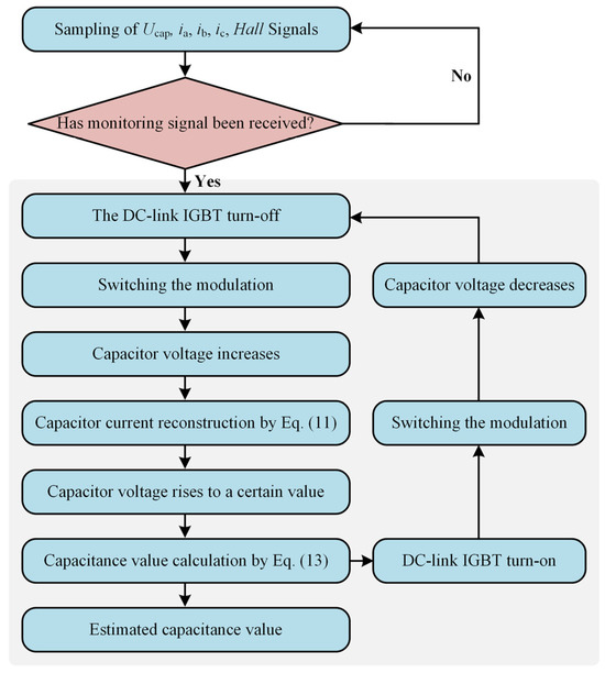
Figure 9.
The flowchart of the capacitor monitoring method.
5. Implementation and Experimental Results
To verify the feasibility of the method proposed in this paper, an experimental platform for the BLDCM system was built, as shown in Figure 10a. The two dc-link electrolytic capacitors used in the experiment are shown in Figure 10b. The controller of the experimental platform consists of a DSP (TMS320F28335) and an FPGA (EPIC6Q240C8), with a switching frequency of 10 kHz. The IGBT model used is FGL40N120. The voltage sensor used in the experiments of this paper is the LV25-P sensor produced by LEM Company in Geneva, Switzerland. The current sensor used is the LAH25-NP sensor produced by LEM Company in Geneva, Switzerland.

Figure 10.
A schematic diagram of the composition of the experimental platform. (a) A physical diagram of the built brushless DC motor system. (b) A physical diagram of the electrolytic capacitor.
The basic parameters of the BLDCM and the DC power supply used in the experimental platform are shown in Table 2. The experimental platform is powered by a Keysight RP7962A DC power supply, with a supply voltage Vdc = 220 V. During the experimental verification process, the motor load will be provided by the MAGTROL motor testing system. The capacitance values of the electrolytic capacitors selected for the dc-link of the motor are C1 = 90.1 μF and C2 = 262.2 μF. Since the capacitance values of aged electrolytic capacitors and healthy electrolytic capacitors do not differ significantly at high temperatures, capacitor monitoring is generally carried out in low-temperature environments. The experiments in this paper were conducted at room temperature.

Table 2.
BLDCM system parameters.
Figure 11 shows the experimental waveform of the dc-link electrolytic capacitor during the charging and discharging phases, with a capacitance value of 90.1 μF, a motor load torque TL of 0.45 N·m, and a speed n of 300 rpm. The figure shows the experimental waveforms from top to bottom as follows: the three-phase currents of the motor, the current of the dc-link capacitor, the capacitor voltage ucap, and the on–off signal S7 of the dc-link IGBT. It should be noted that the current of the dc-link capacitor is only used to prove that the capacitor is charging and discharging, and the charging and discharging currents can be reconstructed from the three-phase currents of the motor.
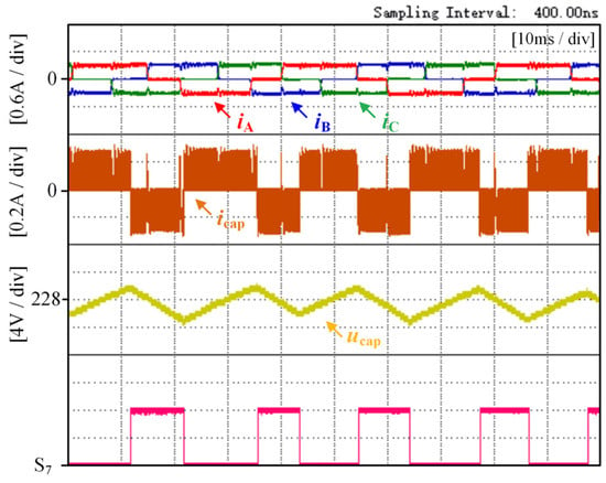
Figure 11.
Schematic diagram showing three-phase currents of motor, capacitor current, capacitor voltage, and dc-link IGBT on–off signal.
As can be seen from Figure 11, when the dc-link switch T7 is turned off, the dc-link capacitor voltage ucap begins to rise under the action of the charging vector Vc. Moreover, according to the waveform of the three-phase currents of the motor, it can be observed that there is no significant change in the motor during the voltage rising phase, which means that the voltage rise of the dc-link capacitor has a relatively small adverse effect on the normal operation of the motor. The stepwise rise of the capacitor voltage also proves that the capacitor voltage rises gradually under the action of multiple charging vectors, which confirms the correctness of the theoretical analysis in the previous section. The amplitude of the capacitor current is the same as that of the three-phase currents of the motor, so it can be reconstructed from the three-phase currents of the motor, as shown in Equation (11).
In order to analyze the effectiveness of the method proposed in this paper and to reduce the impact of random errors, experiments were conducted under three different conditions while the motor was operating in a steady state: with different values of dc-link electrolytic capacitors, under different motor loads, and at different motor speeds. These experiments were carried out to demonstrate the feasibility of the method. The capacitance values of the dc-link electrolytic capacitors were averaged after being calculated using Equation (13) and then output to the oscilloscope via a Digital-to-Analog Converter (DAC) chip for data acquisition.
5.1. Experimental Results and Analysis Under Different Capacitance Values
Figure 12 shows the experimental waveforms of the motor operating under the conditions of a load torque TL of 0.89 N·m and a speed n of 600 rpm, with electrolytic capacitors with capacitance values of 90.1 μF and 262.2 μF used on the dc-link, respectively. The experimental waveforms from top to bottom are the dc-link capacitor voltage ucap, the three-phase motor currents (iA, iB, and iC), the duty cycle d during motor operation (where d = d2 during the capacitor charging period and d = d3 during the capacitor discharging period), the on–off signal S7 of the dc-link switch T7, and the capacitance C of the dc-link electrolytic capacitor calculated using the method presented in this paper. The structure of the experimental waveforms will also be presented in this manner. From the three-phase current amplitude of 0.6 A in Figure 12, it can be seen that the motor is operating at TL = 0.89 N·m. However, since a 262.2 μF electrolytic capacitor is used on the dc-link in Figure 12b, the energy formula of the capacitor is as follows:
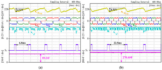
Figure 12.
The experimental waveform of the motor operating under the conditions of a load torque TL of 0.89 N·m and a speed n of 600 rpm. (a) The capacitance value on the dc-link is 90.1 μF, and (b) the capacitance value on the dc-link is 262.2 μF.
With the same load torque TL for the motor and a similar duty cycle for the charging vector, a larger electrolytic capacitor requires more control cycles to increase its voltage by the same amount compared to a smaller one. Therefore, as can be seen from the duration of the charging cycles in Figure 12a,b, one charging cycle in Figure 12b takes more time than that in Figure 12a. Moreover, from Equations (2) and (6), it can be determined that under the operating conditions of a load torque TL of 0.89 N·m and a speed n of 600 rpm, the effective vector duty cycle during the capacitor charging period is approximately 0.85, as shown in Figure 12a,b. It can be seen from the three-phase motor currents and the duty cycle that the duty cycle of the motor is approximately 1 during the commutation period.
Taking Figure 12a as an example, the change in capacitor voltage is 4.51 V, and the capacitor charging time lasts for 6.8 ms. The duty cycle can also be obtained in real time in the controller. By substituting the control period and the reconstructed capacitor current into Equation (9) in the controller, the capacitance value calculated for one charging cycle can be obtained. The capacitance values marked in the figures are the average values. From Figure 12a, it can be seen that the capacitance monitoring result is 89.2 μF, with an estimated error of 0.9%. As seen in Figure 12b, the capacitance monitoring result is 270.4 μF, with an estimated error of 3.1%. The capacitance monitoring error under both steady-state conditions is within 5%. Figure 12 shows the motor operating under steady-state conditions with constant load torque and speed. By changing the capacitance value of the dc-link electrolytic capacitor, it demonstrates that the method proposed in this paper can be effectively implemented for dc-link electrolytic capacitors with different capacitance values.
5.2. Experimental Results and Analysis Under Different Loads
The capacitance of the dc-link electrolytic capacitor was maintained and the motor speed was unchanged to demonstrate the effectiveness and feasibility of the method proposed in this paper under different load conditions. Figure 13 shows the experimental waveforms of the motor with a dc-link electrolytic capacitor with a capacitance of 90.1 μF and a motor speed n of 600 rpm. Figure 13a shows the experimental results under a motor load torque TL of 0.45 N·m, while Figure 13b presents the experimental data with a motor load torque TL of 0.89 N·m.
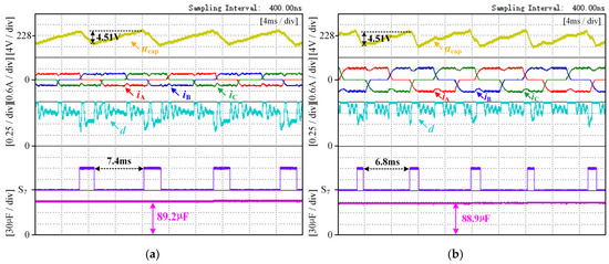
Figure 13.
Experimental waveform diagram with dc-link electrolytic capacitor value of 90.1 μF and motor speed of n 600 rpm. (a) Motor load torque TL = 0.45 N·m. (b) Motor load torque TL = 0.89 N·m.
Since the load torque TL is 0.45 N·m in Figure 13a, the amplitude of the three-phase currents is 0.3 A. In Figure 13b, with the load torque TL being 0.89 N·m, the amplitude of the three-phase currents is 0.6 A. Using Equations (2) and (6), it can be determined that under the operating conditions of a load torque TL of 0.45 N·m and a speed n of 600 rpm, the effective vector duty cycle during the capacitor charging period is approximately 0.78. Under the operating conditions of a load torque TL of 0.89 N·m and a speed n of 600 rpm, the effective vector duty cycle during the capacitor charging period is approximately 0.85. Although an increase in the load torque will increase the charging current, it will also result in a decrease in the duty cycle of the charging vector. Therefore, the charging times for the two cases are not significantly different.
As can be seen from Figure 13a, the calculated capacitance value of the electrolytic capacitor under this working condition is 89.2 μF, with an estimated error of 0.9%. As can be seen from Figure 13b, the calculated capacitance value of the electrolytic capacitor under this working condition is 88.9 μF, with an estimated error of 1.3%. The capacitance monitoring error under both steady-state conditions is within 5%. Figure 13 shows that the capacitance value of the dc-link electrolytic capacitor is constant. The motor operates under a condition of constant speed. By changing the load torque of the motor, the motor is placed in steady-state conditions under different load torques. This indicates that the method proposed in this paper can be effectively implemented for the motor under steady-state conditions with different load torques.
5.3. Experimental Results and Analysis Under Different Speeds
Similarly, by keeping the capacitance value of the DC-link electrolytic capacitor and the load of the motor constant, only the speed of the motor is changed. This can demonstrate the effectiveness and feasibility of the method when the motor operates at different speeds. Figure 14 shows the experimental waveforms when the capacitance value of the dc-link electrolytic capacitor is 90.1 μF and the motor load torque TL is 0.45 N·m. Figure 14a shows the experimental graph when the motor speed n is 300 rpm, and Figure 14b shows the experimental graph when the motor speed n is 600 rpm. Using Equations (2) and (6), the effective vector duty cycle of the capacitor charging period is solved to be approximately 0.67. This value corresponds to the motor operating at a load torque TL of 0.45 N·m and a speed n of 300 rpm. When the motor operates at TL = 0.45 N·m and n = 600 rpm, the duty cycle becomes approximately 0.78. These results are shown in Figure 14.
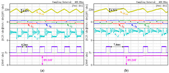
Figure 14.
An experimental waveform diagram with a dc-link electrolytic capacitor value of 90.1 μF and a motor load torque TL of 0.45 N·m. (a) The motor speed n = 300 rpm. (b) The motor speed n = 600 rpm.
As shown in Figure 14a, the capacitor voltage increased by 4.43 V in 4.2 ms, which is equivalent to 42 motor control cycles. As shown in Figure 14b, the capacitor voltage increased by 4.51 V in 7.4 ms, which is equivalent to 74 motor control cycles. Since the load torque TL is 0.45 N·m in both operating conditions, the charging current of the capacitor is the same, which is 0.3 A. However, when n = 300 rpm, the duty cycle of the charging vector is about 0.33, while when n = 600 rpm, the duty cycle of the charging vector is about 0.22. Therefore, Figure 14b, which has a slightly higher voltage increase, requires more control cycles than Figure 14a.
As can be seen from Figure 14, when the motor speed is 300 rpm, the calculated capacitance value is 89.1 μF with an error of 1.1%; when the motor speed is 600 rpm, the calculated capacitance value is 89.2 μF with an error of 0.9%. The capacitance monitoring error under both steady-state conditions is within 5%. Figure 14 shows that the capacitance value of the dc-link electrolytic capacitor remains constant. The motor operates under a condition of constant load torque. By changing the motor speed, the motor is placed in steady-state conditions at different speeds. This indicates that the method proposed in this paper can be effectively implemented for the motor under steady-state conditions with different speeds.
In summary, under steady-state conditions with constant motor load torque and speed, the monitoring method proposed in this paper is applicable to different dc-link electrolytic capacitors; with the dc-link capacitor remaining unchanged and with the motor speed kept constant, the proposed monitoring method is applicable under steady-state conditions with different motor load torques; and with the dc-link capacitor remaining unchanged and with the motor load torque kept constant, the proposed monitoring method is also applicable under steady-state conditions with different motor speeds. Therefore, the method proposed in this paper is applicable under steady-state conditions with different motor load torques and speeds, and it can accurately monitor different capacitance values of dc-link electrolytic capacitors under different steady-state conditions. And the capacitance monitoring error is within 5%.
It should be pointed out that steady-state operation is a common condition for motor operation, and the experimental results mentioned above were all obtained under the premise of the capacitor monitoring method proposed in this paper (the motor operates in steady-state condition). However, the dc-link electrolytic capacitor does not need continuous monitoring; it only requires periodic capacitor monitoring. When the capacitance value is found to have decayed by more than 20% of its initial value, the electrolytic capacitor is deemed to have failed and should be replaced in a timely manner.
5.4. Comparison of Proposed Method with Alternative Methods
The method proposed in this paper is used for the life monitoring of the dc-link capacitor in a BLDCM. The capacitor monitoring methods used in articles [20,21] and article [24] can be applied to the system of the capacitor monitored in this paper and can serve as alternative monitoring methods. The Table 3. provides a direct comparison of the capacitor monitoring methods in the three references with the method proposed in this paper in terms of accuracy and practicality. It should be noted that the comparison presented in this section is based on the results of those papers, and only a theoretical analysis and summary of their papers are provided.

Table 3.
A comparison of the proposed method with alternative methods in terms of accuracy and practicality.
Compared with alternative methods, the method proposed in this paper can be implemented during the electric operation of the motor and has a minimal impact on the normal operation of the motor. When the capacitance value is detected to have decayed by more than 20% of its initial value, the electrolytic capacitor is deemed to have failed and needs to be replaced in a timely manner. Therefore, theoretically, the precision of the capacitor monitoring method can be less than 20%. However, the precision of most current electrolytic capacitor life monitoring methods is below 5%. Therefore, the method proposed in this paper can effectively monitor the dc-link electrolytic capacitor.
It should be particularly pointed out that although the method proposed in this paper can be implemented during normal motor operation and can effectively monitor the capacitor’s life, it requires additional switches and diodes, and the monitoring accuracy needs further improvement.
6. Conclusions
This paper proposes a method for monitoring the life of the dc-link electrolytic capacitor in a BLDCM system powered by a direct current power supply. Firstly, the method introduces a dc-link structure with a series-connected switch on the dc-link. Subsequently, different motor control strategies are switched to charge the dc-link capacitor. Then, the capacitance of the electrolytic capacitor is calculated through its charging curve, enabling the monitoring of the life of the dc-link electrolytic capacitor. The advantage of the monitoring method proposed in this paper is that it can perform capacitor monitoring during the normal electric operation of the motor, with minimal dependence on the system where the monitored capacitor is located. By simply adding a switch and a diode, capacitor monitoring can be carried out, which results in a low cost and a simple algorithm. It is meaningful for improving the reliability of the motor system and realizing the preemptive protection of the power electronic converter. The experimental results show that the proposed method has a minor impact on the electric operation of the motor. The accuracy of the capacitance calculation is maintained within 5%, which can effectively monitor the life of the dc-link electrolytic capacitor. The main features of this paper are as follows:
(1) The proposed method can monitor the lifetime of the dc-link electrolytic capacitor during the normal electric operation of the motor without requiring the motor to be in a special condition or artificially creating conditions for capacitor monitoring.
(2) The capacitor monitoring process does not have negative impacts on the power electronic converter or the load carried by the motor, and it can be implemented multiple times.
(3) The topology introduced in this paper, which is composed of a diode T and switch T7, can monitor the capacitor during the steady-state operation of the motor. However, it also brings certain costs. The presence of the switch and the diode will cause some power losses, but these power losses are much smaller than those of the inverter and the motor.
(4) The capacitor monitoring method proposed in this paper can effectively monitor the lifespan of the dc-link electrolytic capacitor. However, in future work, it is necessary to conduct a detailed quantitative analysis of the impact of adverse factors such as sensor noise and the on–off delay of the switch in order to further improve the accuracy of capacitor monitoring.
(5) In this paper, the introduction of the dc-link diode D will block the regenerative braking energy feedback when the electric vehicle performs regenerative braking and charges the battery. In future research, a transistor can be used to replace the diode. The transistor can be turned on when the motor performs regenerative braking and charges the battery, and it can be kept off during capacitor monitoring and normal motor operation.
Author Contributions
Conceptualization, S.G. and X.L.; methodology, S.X.; software, Z.Q.; validation, Z.Q.; formal analysis, Z.L.; investigation, Z.L.; resources, X.L.; data curation, Z.Q.; writing—original draft preparation, Z.Q.; writing—review and editing, S.G. and X.L.; supervision, S.X.; project administration, X.L.; funding acquisition, X.L. All authors have read and agreed to the published version of the manuscript.
Funding
This research was funded by the National Natural Science Foundation of China under Grant 52477060, the Key Program of Tianjin Natural Science Foundation under Grant 24JCZDJC00250, and the Basic Scientific Research Institute Stability Support Project under Grant WDZC-2023-ZNKZ-01.
Data Availability Statement
The original contributions presented in this study are included in the article; further inquiries can be directed to the corresponding author.
Conflicts of Interest
The authors declare no conflicts of interest. The funders had no role in the design of the study; in the collection, analyses, or interpretation of data; in the writing of the manuscript; or in the decision to publish the results.
References
- Chen, W.; Wu, J.; Li, X.; Li, C. Overvoltage Avoidance Control Strategy for Braking Process of Brushless DC Motor Drives with Small DC-Link Capacitance. Actuators 2024, 13, 185. [Google Scholar] [CrossRef]
- Shukla, T.; Nikolovski, S. A Bridgeless Cuk-BB-Converter-Based BLDCM Drive for MEV Applications. Energies 2023, 16, 3747. [Google Scholar] [CrossRef]
- Chen, X.; Liu, G. Sensorless optimal commutation steady speed control method for a nonideal Back-EMF BLDC motor drive system including buck converter. IEEE Trans. Ind. Electron. 2020, 67, 6147–6157. [Google Scholar] [CrossRef]
- Kim, M.; Lee, K.; Yoon, J.; Lee, S.; Yoo, J. Condition Monitoring of DC Link Electrolytic Capacitors in Adjustable Speed Drives. In Proceedings of the 2007 IEEE Industry Applications Annual Meeting, New Orleans, LA, USA, 23–27 September 2007; pp. 237–243. [Google Scholar] [CrossRef]
- Song, Y.; Wang, B. Survey on Reliability of Power Electronic Systems. IEEE Trans. Power. Electron. 2013, 28, 591–604. [Google Scholar] [CrossRef]
- Peyghami, S.; Wang, Z.; Blaabjerg, F. A Guideline for Reliability Prediction in Power Electronic Converters. IEEE Trans. Power. Electron. 2013, 35, 10958–10968. [Google Scholar] [CrossRef]
- Zhao, Z.; Davari, P.; Lu, W.; Wang, H.; Blaabjerg, F. An Overview of Condition Monitoring Techniques for Capacitors in DC-Link Applications. IEEE Trans. Power. Electron. 2021, 36, 3692–3716. [Google Scholar] [CrossRef]
- Soliman, H.; Wang, H.; Blaabjerg, F. A Review of the Condition Monitoring of Capacitors in Power Electronic Converters. IEEE Trans. Ind. Appl. 2016, 52, 4976–4989. [Google Scholar] [CrossRef]
- Wang, H.; Blaabjerg, F. Reliability of Capacitors for DC-Link Applications in Power Electronic Converters—An Overview. IEEE Trans. Ind. Appl. 2014, 50, 3569–3578. [Google Scholar] [CrossRef]
- Amaral, A.M.R.; Cardoso, A.J.M. An experimental technique for estimating the aluminum electrolytic capacitor equivalent circuit, at high frequencies. In Proceedings of the 2005 IEEE International Conference on Industrial Technology, Hong Kong, China, 14–17 December 2005; pp. 86–91. [Google Scholar] [CrossRef]
- Amaral, A.M.R.; Cardoso, A.J.M. An Experimental Technique for Estimating the ESR and Reactance Intrinsic Values of Aluminum Electrolytic Capacitors. In Proceedings of the 2006 IEEE Instrumentation and Measurement Technology Conference Proceedings, Sorrento, Italy, 24–27 April 2006; pp. 1820–1825. [Google Scholar] [CrossRef]
- Kim, M.; Sul, S.K.; Lee, J. Condition monitoring of DC-link capacitors in drive system for electric vehicle. In Proceedings of the 2012 IEEE Vehicle Power and Propulsion Conference, Seoul, Republic of Korea, 9–12 October 2012; pp. 633–637. [Google Scholar] [CrossRef]
- Wei, X.; Yao, B.; Peng, Y.; Sun, Y.; Wang, K.; Wang, H. An Improved Discharge Profile-Based DC-Link Capacitance Estimation for Traction Inverter in Electric Vehicle Applications. IEEE Trans. Power. Electron. 2024, 39, 8696–8708. [Google Scholar] [CrossRef]
- Buiatti, G.; MartÍn-Ramos, J.; Amaral, A.; Dworakowski, P.; Cardoso, A. Condition Monitoring of Metallized Polypropylene Film Capacitors in Railway Power Trains. IEEE Trans. Instrum. Meas. 2009, 58, 3796–3805. [Google Scholar] [CrossRef]
- Dai, X.; Zhao, L.; Han, L.; Sun, Y.; Chen, J. A High-Accuracy Capacitor Condition Monitoring Scheme at Low Sample Frequency Based on Improved Current Reconstruction Method. IEEE J. Emerg. Sel. Top. Power Electron. 2024, 12, 2281–2291. [Google Scholar] [CrossRef]
- Wu, X.; Li, K.; Yu, T.; Cheng, S.; Huang, Y.; Hu, Y. A Capacitance Estimation Method for DC-Link Capacitors Based on Pre-Charging Model and Noise Evaluation. IEEE Trans. Ind. Electron. 2023, 70, 8477–8487. [Google Scholar] [CrossRef]
- Wu, X.; Li, K.; Tian, R.; Yin, H.; Yu, T.; Cheng, S. A Capacitance Estimation Method for DC-Link Capacitors in Railways Based on Precharging Model and Low Sampling Frequency. IEEE Trans. Power. Electron. 2024, 39, 1527–1537. [Google Scholar] [CrossRef]
- Wu, X.; Wang, D.; Li, K.; Zhuang, P.; Tan, X.; Chen, C. A Capacitance Estimation Method for DC-Link Capacitors in Rail Transit Based on Maximum Likelihood and Variable Convergence Factor. IEEE Trans. Ind. Electron 2025. [Google Scholar] [CrossRef]
- Agarwal, N.; Ahmad, M.; Anand, S. Quasi-Online Technique for Health Monitoring of Capacitor in Single-Phase Solar Inverter. IEEE Trans. Power. Electron. 2018, 33, 5283–5291. [Google Scholar] [CrossRef]
- Ghadrdan, M.; Abdi, B.; Peyghami, S.; Mokhtari, H.; Blaabjerg, F. On-Line Condition Monitoring System for DC-Link Capacitor of Back-to-Back Converters Using Large-Signal Transients. IEEE J. Emerg. Sel. Top. Power Electron. 2023, 11, 1132–1142. [Google Scholar] [CrossRef]
- Meng, T.; Zhang, P. An Online DC-Link Capacitance Estimation Method for Motor Drive Systems Based on an Intermittent Reverse-Charging Control Strategy. IEEE Trans. Power. Electron. 2023, 38, 2481–2492. [Google Scholar] [CrossRef]
- Zhao, Z.; Davari, P.; Lu, W.; Blaabjerg, F. Online DC-Link Capacitance Monitoring for Digital-Controlled Boost PFC Converters Without Additional Sampling Devices. IEEE Trans. Ind. Electron. 2023, 70, 907–920. [Google Scholar] [CrossRef]
- Aeloiza, E.; Kim, J.H. A Real Time Method to Estimate Electrolytic Capacitor Condition in PWM Adjustable Speed Drives and Uninterruptible Power Supplies. In Proceedings of the 2005 IEEE 36th Power Electronics Specialists Conference, Dresden, Germany, 16 June 2005; pp. 2867–2872. [Google Scholar] [CrossRef]
- Abo-Khalil, A.G.; Lee, D.C. DC-Link Capacitance Estimation in AC/DC/AC PWM Converters Using Voltage Injection. IEEE Trans. Ind. Appl. 2008, 44, 1631–1637. [Google Scholar] [CrossRef]
- Vogelsberger, M.A.; Wiesinger, T. Life-Cycle Monitoring and Voltage-Managing Unit for DC-Link Electrolytic Capacitors in PWM Converters. IEEE Trans. Power. Electron. 2011, 26, 493–503. [Google Scholar] [CrossRef]
- Gasperi, M. Life prediction modeling of bus capacitors in AC variable-frequency drives. IEEE Trans. Ind. Appl. 2005, 41, 1430–1435. [Google Scholar] [CrossRef]
- Wu, Y.; Du, X. A VEN Condition Monitoring Method of DC-Link Capacitors for Power Converters. IEEE Trans. Ind. Electron. 2019, 66, 1296–1306. [Google Scholar] [CrossRef]
- Chen, W.; Hui, S. Elimination of an Electrolytic Capacitor in AC/DC Light-Emitting Diode (LED) Driver With High Input Power Factor and Constant Output Current. IEEE Trans. Power. Electron. 2012, 27, 1598–1607. [Google Scholar] [CrossRef]
- Wang, Z.; Zhang, Y.; Wang, H.; Blaabjerg, F. A Reference Submodule Based Capacitor Condition Monitoring Method for Modular Multilevel Converters. IEEE Trans. Power. Electron. 2020, 35, 6691–6696. [Google Scholar] [CrossRef]
Disclaimer/Publisher’s Note: The statements, opinions and data contained in all publications are solely those of the individual author(s) and contributor(s) and not of MDPI and/or the editor(s). MDPI and/or the editor(s) disclaim responsibility for any injury to people or property resulting from any ideas, methods, instructions or products referred to in the content. |
© 2025 by the authors. Published by MDPI on behalf of the World Electric Vehicle Association. Licensee MDPI, Basel, Switzerland. This article is an open access article distributed under the terms and conditions of the Creative Commons Attribution (CC BY) license (https://creativecommons.org/licenses/by/4.0/).