1. Introduction
Hybrid electric vehicles combine the advantages of engines and electric motors, reducing energy consumption and improving the vehicle’s energy utilization efficiency through the switching of multiple operating modes. Before the power continuity problem of electric vehicles is completely solved, hybrid electric vehicles, equipped with multiple energy storage systems, have relatively low dependence on oil. In the face of global warming, oil consumption, and environmental pollution, a solution is proposed [
1,
2,
3]. Due to the combination of the engine and motor, a major feature of hybrid vehicles is that they bring both advantages and disadvantages. The response characteristics of the engine and the motor have significant differences, and it is necessary to maintain stable output of the power system during vehicle mode switching and driving to avoid sudden power changes [
4]. On the other hand, mode switching during driving conditions such as starting, accelerating, and uphill movement can cause vibration in the transmission system, which not only affects the driving smoothness and power of the vehicle, but may also affect the reliability of the system [
5]. A reasonable mode switching strategy is needed to avoid these problems. The mode switching strategy is one of the most important functions for hybrid vehicles, so research on mode switching control strategy for hybrid vehicles is of great significance. The MPC method has been widely applied in vehicle control, which provides a foundation for this research [
6,
7]. MPC has good robustness and practical application effects, ensuring that vehicles can achieve efficient and stable control effects under various conditions [
8]. During the mode switching process of hybrid vehicles, the system state includes both continuous dynamic variables such as engine speed and motor torque, as well as discrete logical variables such as clutch engagement status and power source start stop. This continuous discrete mixed characteristic forms a hybrid dynamic system with state jump characteristics, and the traditional MPC framework based on continuous differential equation modeling is difficult to fully describe such systems.
For this purpose, hybrid model predictive control uses a mixed logic dynamic (MLD) modeling framework to integrate discrete events and continuous dynamics into optimization problem solving, which is particularly suitable for handling multimodal characteristics during mode switching processes. By constructing a mixed integer programming model that includes Boolean and continuous variables, not only can the continuous state evolution of the power system be predicted, but discrete control decisions can also be optimized to ensure smoothness while maximizing energy efficiency. In the process of handling hybrid system optimization control problems, HMPC has gradually taken shape and been further developed. HMPC combines the ability of MPC to predict future system behavior, and extends it to address hybrid characteristics. It can simultaneously consider the dynamic constraints and operational limitations of the system, achieving optimal system performance within a predetermined time range. It has become an important tool for solving control problems of systems with hybrid dynamic characteristics.
Esfandyari et al. [
9] proposed a hybrid control system based on MPC and fuzzy logic for estimating the power state of lithium-ion batteries. The proposed estimation method was validated in the feedforward simulation model of HEV. The results indicate that this method can accurately estimate the power state of the battery pack while ensuring the safe operation of the battery. Karami Z et al. [
10] proposed a hybrid model predictive controller to ensure the stability of DC microgrids and improve the performance of DC-DC boost converters that interface with constant power loads in hybrid systems. The effectiveness of the proposed hybrid model predictive control was verified through comparative evaluation with discrete-time average model predictive control, continuous control set MPC, and traditional PI control. Significant contributions have been made in the fields of battery management and microgrid control, but their simplified models and limited scenarios make it difficult to directly adapt to the complex control requirements of hybrid mining dump trucks.
Honek et al. [
11] applied HMPC to the control of air–fuel ratio in gasoline engines, based on a nonlinear model to track the dynamic fuel mass flow reference values of the air and fuel paths in the cylinder, and then used the hybrid model for model predictive control, achieving good control results. Zhang Sheng [
12] addresses the energy management issues of hybrid electric vehicles by comprehensively considering multiple operating modes and states of the vehicle, including the operating states of the engine and electric motor, as well as the battery charging and discharging process, vehicle speed and acceleration requirements, etc. The optimization of power source output torque based on the HMPC strategy has improved the fuel economy of the vehicle. Jiang Dongdong [
13] adopted the HMPC strategy to optimize and control the energy management problem of hybrid electric vehicles, effectively improving fuel economy by controlling the vehicle’s power system. Currently, HMPC has made significant progress in the fields of air–fuel ratio control and energy management. However, its single-scenario focus and insufficient consideration of the limitations of dynamic impact and mechanical losses during mode switching make it difficult for it to meet the stringent requirements for dynamic coordination and reliable hybrid mining dump trucks.
Sirmatel et al. [
14] developed an innovative dynamic model for single-line bus systems which combines the processing capabilities of continuous and binary states. By precisely adjusting the intervals between buses, the model improves the overall operational efficiency of the bus system. The model also helps optimize vehicle operating speed and stopping strategies, further reducing energy consumption and operating costs. Chen Wuwei et al. [
15] developed a multi-mode switching strategy based on HMPC for the steering system of intelligent vehicles, proposing three different control modes: damping mode, hold mode, and lane changing mode. Each mode is tailored to specific driving needs or conditions to ensure flexibility and adaptability in steering control. Lin Cheng [
16] applied hybrid model predictive control theory to design a torque distribution lower-level controller for wheel drive electric vehicles which is used to enhance the stability of the vehicle under various driving conditions. This control strategy can adjust the output of each wheel hub motor to ensure that the vehicle remains stable in complex situations, effectively avoiding potential instability situations. Sun Xiaoqiang [
17] used the HMPC algorithm to adjust the height and attitude of the electronically controlled air suspension system (ECAS) on buses, in order to reduce the switching frequency of solenoid valves and accurately control the height of the vehicle. Through real vehicle experiments, it has been verified that the HMPC algorithm can not only achieve accurate control of vehicle height and optimized adjustment of posture, but also effectively avoid frequent switching of solenoid valve states. The existing HMPC research mainly focuses on passenger cars or fixed route bus systems, and does not cover the extreme working conditions of high load and frequent multi-mode switching of mining dump trucks.
In response to the extreme working conditions of high load and frequent multi-mode switching of mining dump trucks, this article reveals the essential contradiction of the mode switching process through system analysis: continuous dynamic parameters (such as engine speed and hydraulic pressure) are deeply coupled with discrete logic events (such as clutch start stop and transmission mode switching), and state transitions have a significant impact on system performance. To address the control challenge of hybrid systems, innovative research has introduced hybrid model predictive control (HMPC) into the field of mode switching. Based on the hybrid logic dynamics (MLD) model, a collaborative optimization framework for multi-mode hybrid systems has been constructed, integrating discrete logic variables and continuous dynamic equations to accurately describe the interaction mechanism between state transitions and dynamic evolution, achieving a balance between dynamic mutation suppression and energy loss minimization.
2. Modeling of Hybrid Mining Dump Truck
The hybrid system can provide more power and improve the acceleration performance of the vehicle. Based on the specific application scenario of the mining dump truck, the power split hybrid system is selected as the structural configuration of its power system. By covering the typical mode switching operation modes, system performance boundaries, and industry standard requirements, the actual working needs of hybrid mining dump trucks can be met, enhancing the scientificity of scene design and the generalization of conclusions. This chapter first analyzes the model of the hybrid system, and then establishes the hybrid transmission system model, power source model, hydraulic control model, clutch model, and vehicle longitudinal dynamics model to better understand the dynamic characteristics of the system. Through the modeling work in this chapter, it provides a basis for the subsequent research on the mode shifting process control of the hybrid system, so as to solve the mode shifting control problem in the subsequent simulation.
2.1. System Structure and Working Principle
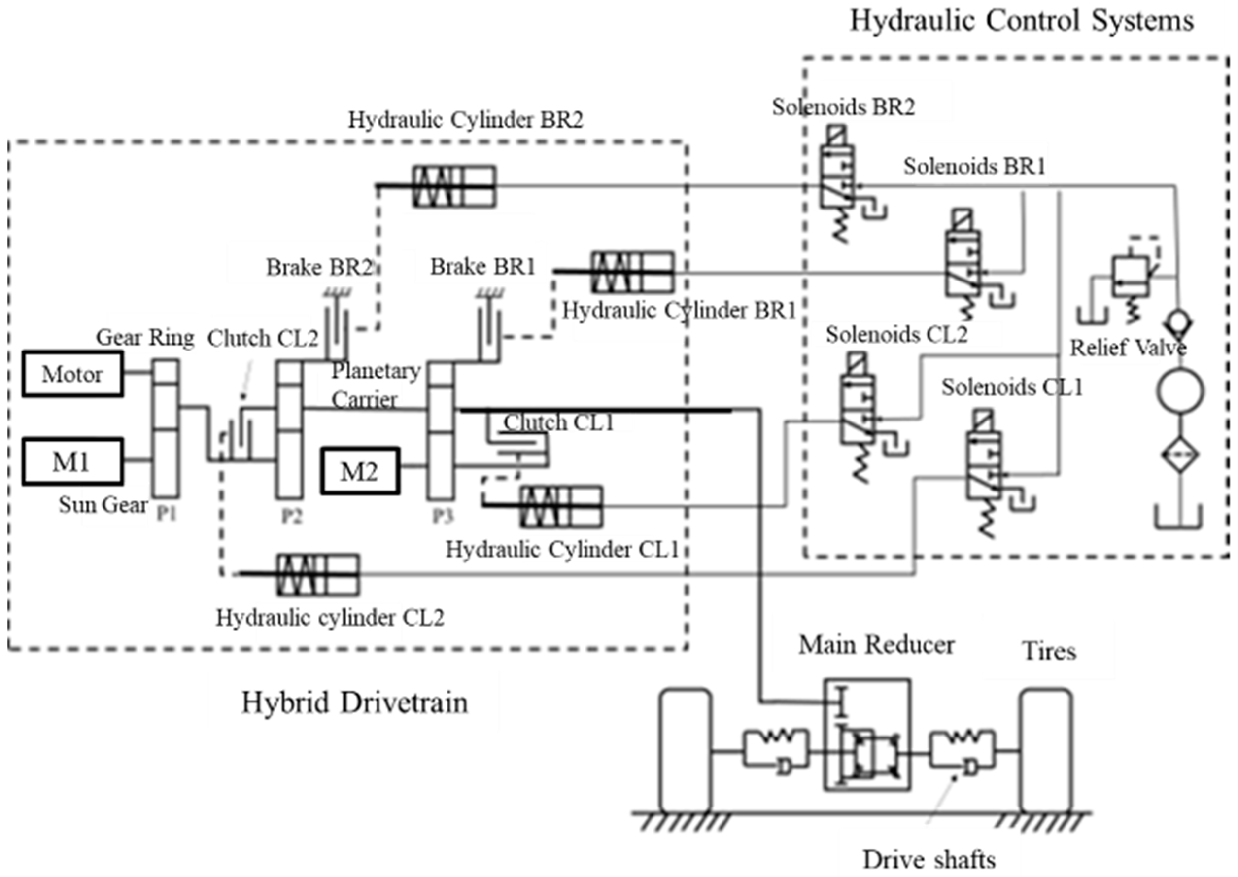
The hybrid transmission system selected in this paper is a power-split hybrid system with three rows of planetary gears. The power transmission system is composed of a diesel engine, two servomotors (M1, M2), coupled planetary gear sets and a hydraulic control system, as shown in
Figure 1. The motor can select the electric mode or power generation mode according to the actual demand, so it can also be expressed by M/G1 and M/G2. The system does not use a traditional transmission, but uses three coupled planetary gear sets (P1, P2, P3) and four clutch/brake configurations (CL1, CL2, BR1, BR2).
2.2. Dynamic Model of Planetary Gearing
The planetary gear is a complex transmission system. Its transmission process involves multiple components with more complex characteristics. Any component can be used as an input or output, and a variety of transmission ratios can be achieved by restricting the movement of some components. Through ingenious design, the planetary gear can flexibly select the input or output to meet specific work requirements. By restricting the movement of the planetary carrier, different transmission ratios can be achieved, providing more transmission options to adapt to different working conditions.
Based on the basic principle of gear transmission [
18], neglecting the elastic deformation and meshing clearance of gears and planetary carriers may lead to torque distribution errors under high-frequency vibration conditions; the dynamic relationship between the components in the planetary gear system can be derived, as shown in Equation (1). These equations can be used to describe the interaction between the various components and reveal the dynamic behavior of the mechanism under various operating conditions.
where
is the speed of the sun wheel, rad/s;
is the rotational speed of the planet carrier, rad/s;
is the speed of the ring gear, rad/s;
is the radius of the sun wheel, m;
is the radius of the ring gear.
The torque relationship between planetary gears is shown in Equation (2).
where
is the characteristic parameter of the planetary row (the ratio of the number of teeth of the ring gear and the ring gear),
is the torque of the ring gear, Nm;
is the planet carrier torque, Nm.
In vehicle operation, according to the different engagement and disengagement states of the clutch and brake in the planetary gear mechanism, the transmission system in this paper can be divided into six operation modes, as shown in
Table 1. Each mode corresponds to different operating conditions and can be shifted to different transmission modes according to different driving conditions.
When the hybrid transmission system is in Mode 1, it is in pure electric mode, it is combined with Clutch CL1. The M/G2 is directly connected to the output. The torque generated by it can be directly transmitted directly to the output side without passing through a planetary gear mechanism, which reduces the loss in the energy transfer process and is more efficient.
where
is the required torque, Nm;
is the engine output torque, Nm;
is the output torque of motor M/G2, Nm;
,
,
are the characteristic parameters of P1, P2, and P3. Based on the power requirements of hybrid mining dump trucks, the gear ratio is determined through theoretical calculations or optimized design to meet performance goals under different working modes,
,
, and
.
In the hybrid transmission system, when the system is shifted to Mode 2, it is a pure electric mode, and brake BR1 and the clutch CL1 are engaged. Unlike in Mode 1, in this mode, the planetary P3 gear plays a role in torque amplification, thus increasing the output torque of M/G2 and satisfying the demand for higher torque at the output side of the transmission.
When the hybrid transmission system is in Mode 3, it is in hybrid mode. Brake BR1 engages with brake BR2. In this mode, the output torque is composed of two sources. The first is the torque generated by the motor M/G2, which is amplified by the P3 planetary gear and acts on the output side. The second is the torque generated by the engine and motor M/G1, which is also transmitted to the output side through the action of the P1 and P2 planetary rows. The combination of these two sources of torque provides the total torque required at the gearbox output.
When the hybrid transmission system is in Mode 4, it is in hybrid mode. Brake BR2 and Clutch CL1 are combined. The difference from Mode 3 is that M/G2 is directly connected to the output without a planetary gear transmission.
When the hybrid transmission system is in Mode 5, it is in hybrid mode. Brake BR1 and Clutch CL2 are combined. In this mode, the output torque is also composed of two sources. Unlike Mode 3, the torque generated by the engine and motor M/G1 does not pass through the planetary row P1 and P2, and is directly applied to the output side.
When the hybrid drive system is in Mode 6, it is in hybrid mode. Clutch CL1 is engaged with Clutch CL2, and planet carrier P1 is directly connected to the output side, which reduces the power transmission path. At the same time, M/G2 is directly connected to the output side, which provides the driving force to the output shaft. Since the P1 planetary carrier and M/G2 are directly connected to the output side, this layout makes the engine and M/G2 more flexible in the speed range when providing power.
2.3. Hydraulic Control System Model
The hydraulic system achieves mode switching by adjusting the clutch pressure, and its dynamic characteristics directly affect the engagement speed of the clutch and the smoothness of torque transmission, accurately controlling the clutch pressure.
- (1)
Mathematical model of solenoid valve
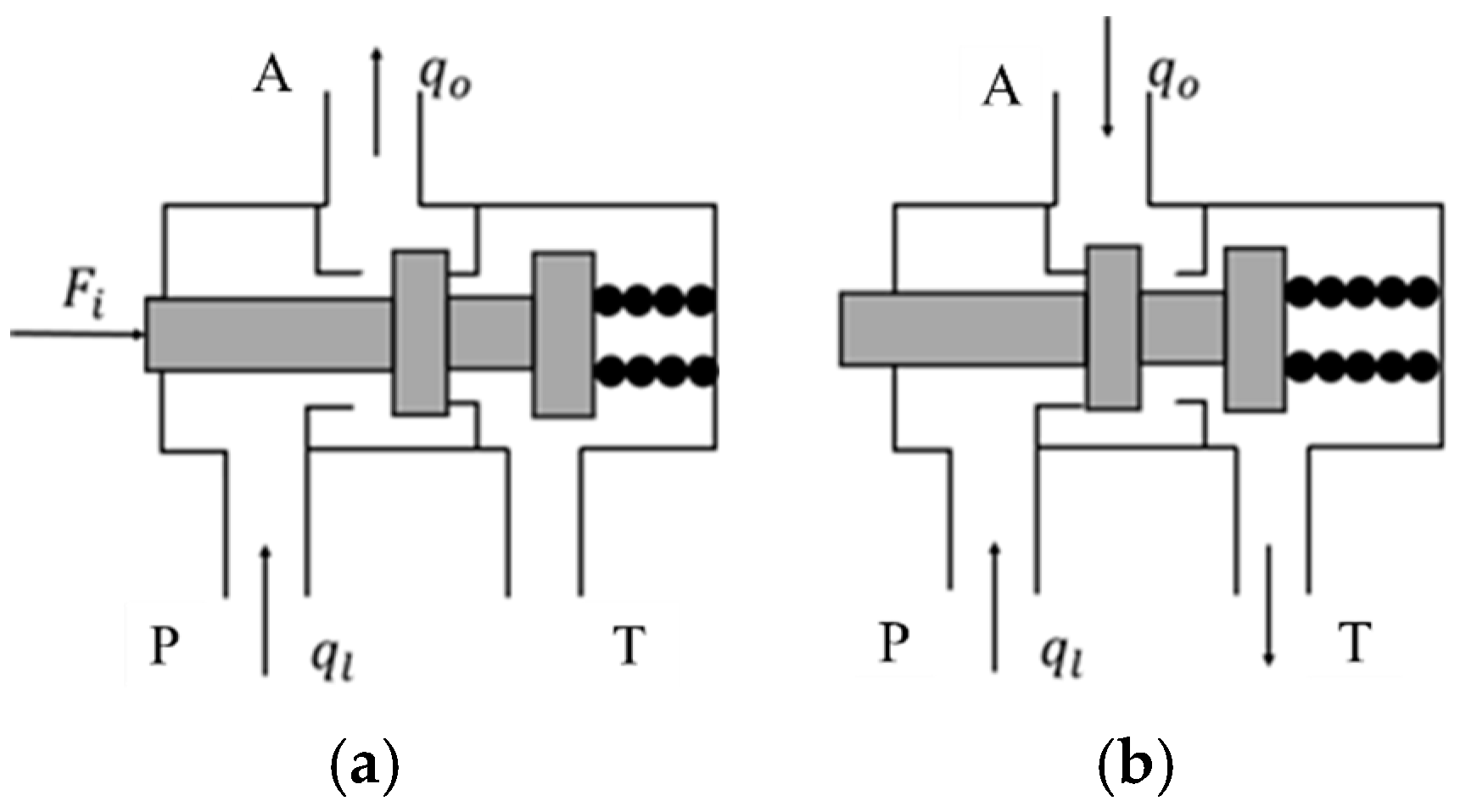
The mathematical model of proportional pressure solenoid valve is established by analytical method [
19], and its working principle is shown in
Figure 2. A port is the oil outlet, P port is the oil inlet, and T port is connected to the oil tank. The final mathematical model must be adjusted and verified in combination with the actual solenoid valve design and experimental data to ensure the accuracy and reliability of the model. In the actual modeling process, it is also necessary to refer to the relevant engineering manuals and standards, as well as experimental tests to obtain the necessary parameters.
The spool of the proportional pressure electromagnetic valve is subjected to feedback cavity pressure, spring elastic force and hydraulic force, among other forces. As a result, the following differential equations can be obtained:
where
is the force of the electromagnet acting on the slide valve when the proportional pressure solenoid valve is energized, N;
is the hydraulic pressure in the proportional pressure solenoid valve chamber, Pa;
is the area of the oil in the proportional pressure solenoid valve cavity acting on the solenoid valve core,
;
is the hydrodynamic force of oil in steady state, N;
is the mass of the solenoid valve, kg;
is the spool displacement of proportional pressure solenoid valve, m;
is the damping coefficient of oil,
;
is the viscous friction coefficient generated by the movement of the spool,
;
is the stiffness of the spring;
is the initial compression of the return spring of the proportional pressure solenoid valve, m. According to the principle that the inlet and outlet flow of the proportional pressure solenoid valve are equal, Neglecting the compressibility and viscosity temperature dependence of oil may lead to pressure prediction bias under high pressure or extreme temperatures, the flow balance equation can be derived as follows:
where
is the oil flow rate into the proportional pressure solenoid valve, L/min;
is the inflow flow in the clutch piston cylinder, L/min;
is the sum of the leakage flow throughout the valve body, L/min;
is the sum of the volume of the oil circuit in the clutch system and the volume of the clutch hydraulic cylinder,
;
is the first derivative of the pressure change with time after the clutch is filled with oil, Pa/s.
- (2)
Clutch hydraulic cylinder mathematical model
According to the movement of the piston during the engagement of the clutch master and slave actuators [
20], the equation of Equation (11) can be obtained as follows:
where
is the mass of the piston, kg;
is the initial displacement of the spring, m;
is the spring stiffness;
is the sum of the external forces on the piston, N;
is the displacement of the piston, m;
is the velocity of piston motion, m/s;
is the acceleration of piston motion,
.
The following Equation can be derived from the pressure generated by the oil flowing into the piston cylinder:
where
is the flow of oil into the piston cylinder, L/min;
is the action area of oil,
;
is the bulk modulus of elasticity of oil,
is the sum of the volume of the oil circuit and the piston cylinder at the initial position,
.
The pressure in the piston cylinder is determined by the intensity of the input current of the proportional pressure solenoid valve. The dynamic behavior of the proportional pressure solenoid valve can be simplified to a first-order system, as previously outlined in the literature [
21].
where
is the time constant of the solenoid valve;
is the gain of the solenoid valve;
is the current of the solenoid valve.
2.4. Friction Torque Model of Clutch
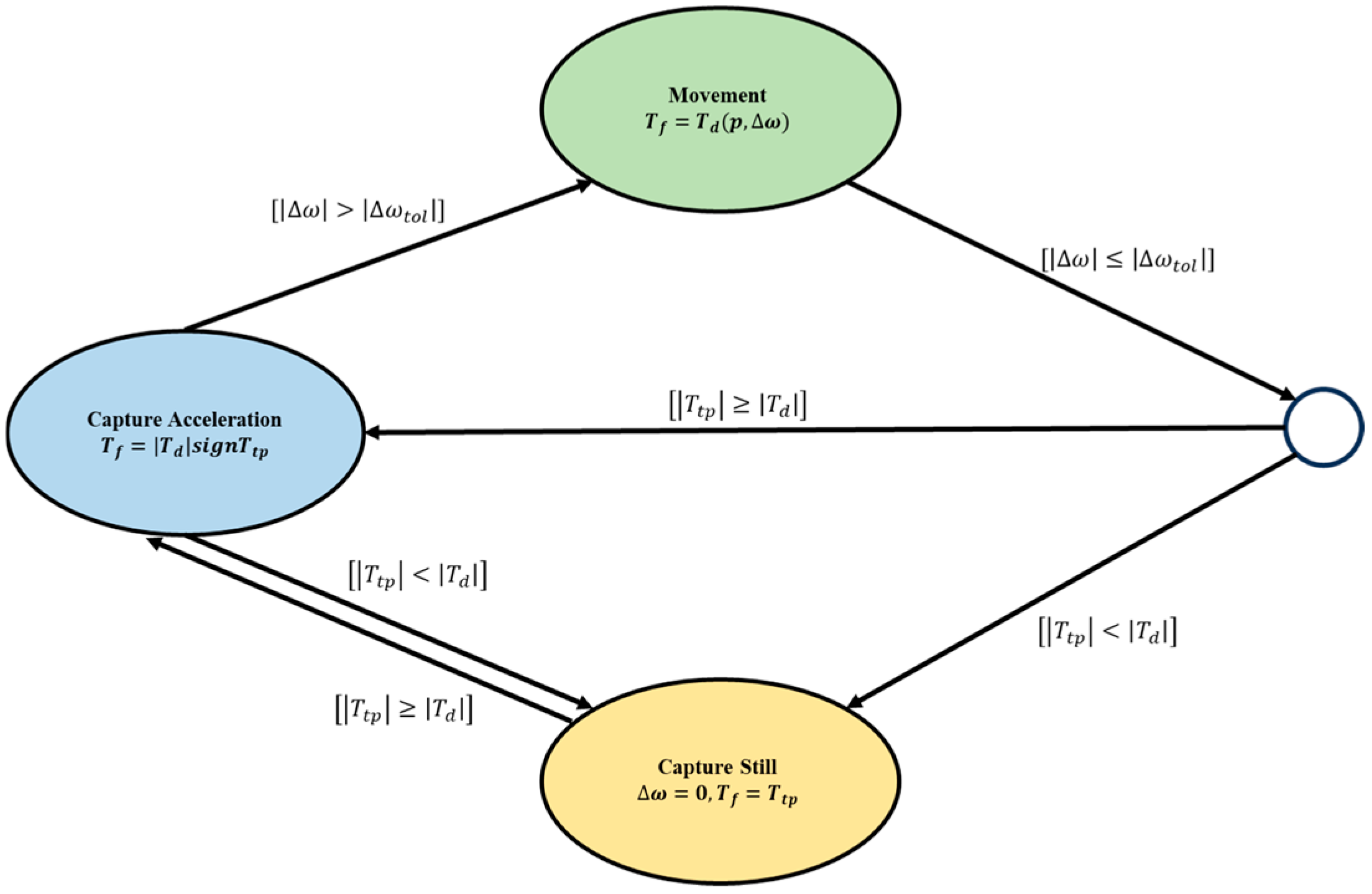
The clutch plays a role in power transmission and buffering during mode switching, and its friction characteristics directly affect sliding friction and impact. The operational mode of the clutch can be categorized into three distinct modes: motion mode, capture acceleration mode, and capture stationary mode. The conversion relationship between these three modes is illustrated in
Figure 3 [
22,
23].
signifies the friction torque generated by the contact surface when the two rotating parts rotate relatively [
24].
denotes the friction torque generated by the contact surface when the relative speed reaches zero.
represents the friction torque transmitted by the clutch, and
denotes the set threshold, with a value of 0.1 rad/s.
In the event that the clutch is operated in three distinct modes, the transmitted friction torque
is as follows:
where
is the captured acceleration torque,
;
is the captured standstill torque,
.
2.5. Vehicle Longitudinal Dynamics Modeling
During the driving process, the vehicle dynamics converts the output of the transmission system into actual motion, directly affecting acceleration and driving smoothness. In addition to the driving force, the vehicle is subjected to various forms of resistance while in motion. These resistances include rolling resistance
, air resistance
, ramp resistance
, and acceleration resistance
, which can be attributed to the power output element, such as an engine or an electric motor, from which the vehicle derives its motive force. The equation for the vehicle’s travel is as follows:
where
;
;
;
.
Prior to and following the mode transition, the vehicle’s acceleration capability is significantly constrained. Consequently, the resistance to acceleration during mode transition can be estimated as negligible. Concurrently, the duration of the mode transition is brief, and the rate of change in the gradient of the roadway is minimal over a relatively short interval. This allows for the approximation of ramp resistance as well. Therefore, during the mode transition process, the external load moment on the wheel is shown below.
3. Mode Switching Control Strategy Based on HMPC
The hybrid transmission is a paradigmatic hybrid process, wherein the clutch operates in multiple operating modes during the mode switching process. The MPC algorithm is incapable of comprehensively describing this mode switching process of the hybrid system. Consequently, the hybrid model is employed to more comprehensively describe the mode switching process of the hybrid mining dump truck. This chapter provides a comprehensive overview of the classification of various hybrid system models. The Mixed Logical Dynamical (MLD) model, which integrates continuous and discrete variables, offers a more comprehensive description of system behavior. This paper employs the MLD model to construct the hybrid part of the model for mode switching, and the hybrid model predictive controller is designed based on the MLD model.
3.1. Mode Switching Quality Evaluation Index
- (1)
Shift Shock Intensity
Hybrid drivetrains facilitate seamless and uninterrupted transitions between various drive modes, a commendable objective in mode switching. However, in practice, the presence of rotational inertia in transmission components and other drive elements inevitably results in a disruptive shock during mode transition. The magnitude of this shock is primarily influenced by the vehicle’s longitudinal acceleration and its rate of change. This analysis does not consider changes in the vehicle’s acceleration in the transverse and vertical directions, such as those produced by steering or road surface unevenness [
25]. The expression for the degree of impact is given by:
where
is the rotational speed of the output shaft of the hybrid drivetrain,
,
is the main deceleration ratio, and
is the radius of the wheels,
. When the degree of impact is greater than 0, it means that the vehicle impact is positive, the increase in acceleration leads to the occupant leaning back. This phenomenon is particularly evident during periods of rapid acceleration. When the impact degree is less than 0, the vehicle’s impact is negative, leading to a reduction in acceleration that results in the occupant leaning forward and a decline in vehicle comfort.
- (2)
Friction Work During Gear Shifting
The relative velocity difference between the master and slave plates of the clutch friction pair leads to sliding friction and thus sliding work, which not only causes energy loss but also reduces the service life of the components. Consequently, the magnitude of sliding friction work is employed as a metric to assess the quality of the mode switching process within a hybrid drivetrain.
where
is the starting moment of mode switching,
;
is the ending moment of mode switching, s;
is the friction torque generated by the clutch, Nm;
is the rotation speed of the active part of the clutch, r/min;
is the rotation speed of the slave part of the clutch, r/min.
The present study focuses on the inertial phase control during the switching process from mode 6 to mode 5. The rotational speed difference between the master and slave plates of brake BR1 is controlled (referred to as the rotational speed of brake BR1). The
also plays an important role in the mode switching process; therefore, the state equation of the system is shown as follows:
3.2. Reference Trajectory
The mode switching process should be characterized by optimal smoothness and minimal slip losses. A reduction in the slip loss of the clutch can be achieved by ensuring that the mode switching time is brief and that the relative speed of the brake/clutch is adequately regulated during the mode switching process. To mitigate the impact of this transition, it is essential that the master and slave plates of the clutch satisfy the no-shock condition at the instant of synchronization. That is to say, the rotational acceleration of the clutch input must be equal to the rotational acceleration of the output [
26]. This condition ensures a seamless and undisturbed transmission of power, thereby reducing the transmission shock.
In order to improve the quality of the vehicle mode switching process, it is necessary to design a reasonable reference trajectory and complete the mode switching within the expected time; At the end of the mode switch, the clutch rotation acceleration is zero; At the beginning of mode switching, the rotational acceleration of the clutch should be minimized to avoid saturation of the control input;
On the basis of meeting these conditions, the control strategy during the clutch engagement process should achieve the following two objectives: the clutch speed should track the expected trajectory well; Minimize the impact during mode switching as much as possible and improve the quality of mode switching.
In order to meet the various requirements for mode switching quality.. There are numerous methods to realize such a trajectory; among these methods, the use of a cubic polynomial in time to construct this trajectory is a common and effective strategy [
27]. This approach is delineated in Equation (20), while the derivative of this function is elucidated in Equation (21).
where
is the target rotational speed of brake BR1, rad/s;
is the rotational speed of brake BR1 at the beginning of the inertial phase, rad/s;
is the mode switching start time, s;
is the end time, s;
is the target angular acceleration, rad/s
2.
3.3. Cost Function
The mode switching control strategy is predicated on the coordination of the timing and impact of the switching process, with the objective of enhancing the performance of mode switching in hybrid vehicles. The objective is to ensure that the rotational speed of brake BR2 aligns seamlessly with the pre-established trajectory, exhibiting both smoothness and precision. Ensuring the dynamics and smoothness of the hybrid vehicle throughout the switching process is also imperative. The reference sequence for the clutch speed is as follows.
where
. Therefore, the problem of optimal control of the clutch during the hybrid drivetrain mode can be described by the following Equation (23).
where
Matrix
is the mode switching time that maximizes the expected mode switching process, while
limits the impact of mode switching. By adjusting matrices
and
, the conflicting control requirements during mode switching can be effectively balanced. The adjustment of these weight matrices not only affects the performance and efficiency of the system, but also directly relates to the dynamic stability of the clutch system and the quality of mode switching.
It is imperative to ensure that the speed of brake BR1 is seamlessly aligned with the desired trajectory. Moreover, the mode switching process should be executed with fluidity and without any disruptions, adhering to the stipulated timeframe. It is essential to maintain the amplitude of the control quantity within acceptable limits to mitigate shocks during the mode shifting of the hybrid system.
4. Mode Switching Process HMPC Design
4.1. MLD Model Construction
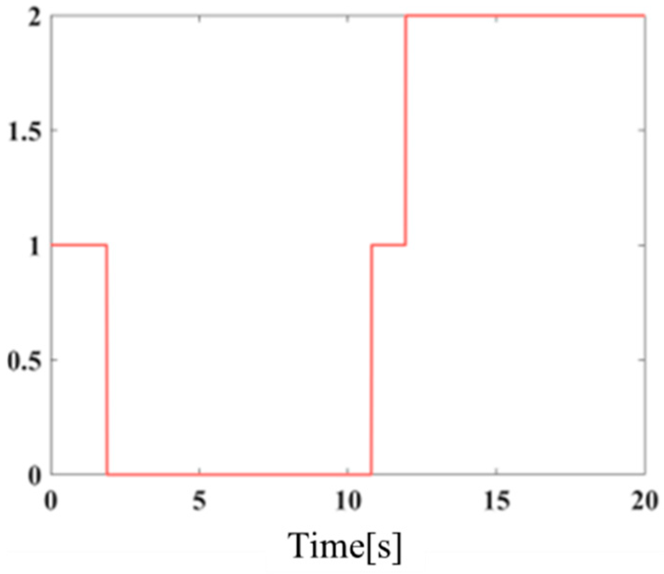
The hybrid mining dump truck’s mode switching process involves a brake binding process that is divided into three typical discrete operating modes, as illustrated in
Figure 4. The process of switching between modes is a typical mixing process. The behavior of the mixing dynamics in the hybrid transmission mode switching process is analyzed, and the MLD model is established for the system by combining the system dynamics model and the HYEDEL modeling specification. This is performed in the following steps.
- (1)
Defining system variables and parameters
The system state variables of the MLD model in the hybrid transmission mode switching process contain both continuous and discrete variables, among which the rotational speed
of the brake BR1 and the pressure
are continuous variables, and the discrete variable is
, which denotes brake BR1 in different operating modes; the system control variable is the current
of brake BR1. The rotational speed
of the brake BR1 is the key index of the system’s control performance, so
is selected as the output variable. The specific form of the system parameters is as follows:
- (2)
Defining auxiliary variables
The utilization of auxiliary variables has been demonstrated to facilitate the comprehension and management of complex expressions by rendering the constraints of the system more lucid and intuitive. For the above system, three auxiliary discrete variables
are introduced.
Introducing auxiliary continuous variables
,
- (3)
The continuous variable update equation is defined.
Due to the inherent discrete-time nature of the MLD model, the continuous state variables in the system must be discretized to obtain Equation (31).
The continuous-state variable update equation actually used for system MLD modeling is as follows:
As demonstrated by the aforementioned formulas, the standard MLD model can be constructed by employing the HYSDEL language. The utilization of the MLD model as the prediction model of MPC enables the construction of a mixed-model predictive controller for the control of mode switching processes in hybrid mining dump trucks.
4.2. Predictive Controller Design for Hybrid Systems Based on MLD Modeling
The optimal control optimization problem for the entire system can be expressed as follows by combining the MLD model and the MPC algorithm, which were previously established.
where
,
,
,
,
were given in
Section 2, and in order to facilitate the optimization solution, the following matrices
,
are defined:
In accordance with the defined vectors and the constructed MLD model, the prediction of the system’s output equations for subsequent steps is feasible, as demonstrated in the following equation:
Substituting Equation (37) into Equation (36) yields the following expression for the system’s objective function:
where
The constraint can be written as .
This can be further written as
Equation (39) can be further written as follows:
formula
.
According to the mathematical analysis previously presented, the optimization solution problem is converted into a standard mixed integer quadratic programming (MIQP) problem, as indicated by the following mathematical expression:
The above MIQP problem is solved online at each sampling moment, and the first element of the solved will is extracted for the controlled system.
5. Control System Simulation Analysis
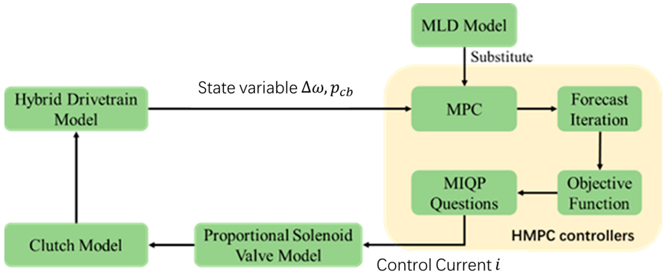
The HMPC algorithm is implemented using MATLAB/SimulinkR2023a software to explore the control effect of HMPC and combine it with the hybrid drivetrain model for control simulation. The overall simulation framework is depicted in
Figure 5. In this framework, the prediction model of MPC is substituted with the MLD model. At any given sampling moment, the MLD model acquires the state variables such as speed and the pressure of brake BR1 from the system model for prediction iterations. Subsequently, the MLD model is integrated with the objective function, thereby converting the optimization problem into a MIQP problem for resolution, and outputting the optimal control current. The control current, in turn, regulates the rotational speed of the brake BR1 by modulating the pressure of the hydraulic cylinder BR1, thereby enhancing the performance of the mode switching process. The brake strategy enables continuous monitoring of the mode switching process of the hybrid mining dump truck, facilitating precise control of the vehicle powertrain mode switching and enhancing its quality.
In evaluating the application and effectiveness of HMPC and MPC in the mode switching process, the primary concern is the ability of these two control strategies to enhance the mode switching performance of the hybrid drivetrain. Secondly, a notable disparity in computational complexity exists between the two approaches when addressing the mode switching problem in hybrid powertrains. The MPC algorithm enhances the quality of mode switching in the hybrid powertrain; however, it necessitates a more extended computation time. The HMPC employs the MLD model of the hybrid system as the prediction model of the MPC algorithm. However, the limitation of the MLD model in modeling nonlinear components necessitates a sequential process of nonlinear component processing followed by the construction of the MLD model, with the objective of minimizing control time.
Sensitivity analysis plays a crucial role in predictive control strategies, playing an indispensable role in optimizing control effects, improving system robustness, and enhancing decision-making scientificity [
28,
29]. On the basis of model predictive control, hybrid model predictive control is used for optimization, and sensitivity analysis is conducted by comparing parameters such as prediction time domain. In the context of the simulation, the step size has been set to 20, as illustrated in
Table 2. This table presents a comparative analysis of the simulation time between HMPC and MPC and EC under various prediction time domains. The results indicate that the simulation time of the hybrid model predictive control (HMPC) decreases by approximately 27% in comparison with that of MPC. It is evident that as the prediction trial time domain increases, the efficacy of HMPC becomes more pronounced. The simulation time of HMPC decreases by approximately 35% compared with that of topable control, owing to the real-time calculation of the weight matrix. HMPC enhances the quality of mode switching and significantly reduces computation time while ensuring the switching effect, thereby improving the real-time and robustness of the control process. This makes HMPC more suitable for mode switching in hybrid drivetrain systems.
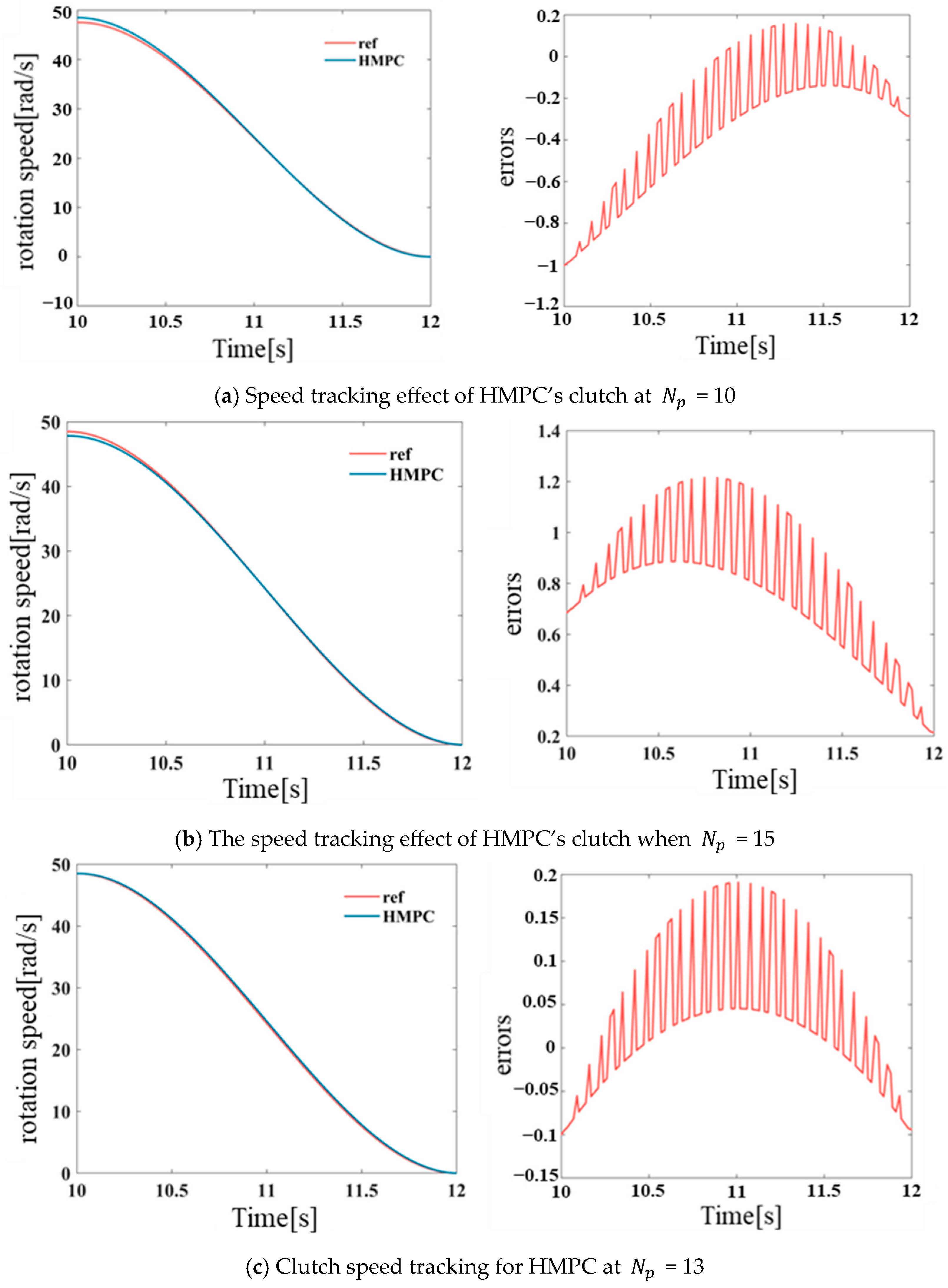
As illustrated in
Figure 6, the rotational speed tracking capability of brake BR1 on the reference trajectory is demonstrated under various HMPC prediction time domains. Subsequent to the execution of repeated tests on distinct prediction time domains, it was ascertained that when the prediction time domain is set to 13, brake BR1 exhibits the optimal tracking capability on the reference trajectory. This results in the minimization of impact degree and sliding friction work generated during mode switching. Consequently, simulation and analysis are conducted for the HMPC prediction time domain of 13.
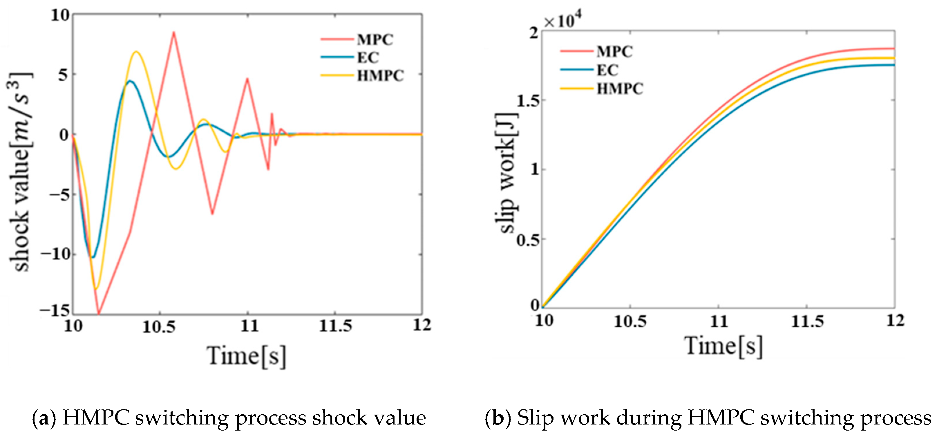
As shown in
Figure 7, a comparison of the impact degree and slip work between HMPC and MPC and EC in the hybrid mode switching process is demonstrated. The simulation results indicate that the impact degree of the hybrid mining dump truck in the mode switching process based on HMPC is less than 13
, and the slip work is approximately 19,000
J. In comparison with the traditional MPC, the impact degree and slip work of HMPC in the mode switching process are reduced, although they are slightly higher than they are under other forms of control. As illustrated in
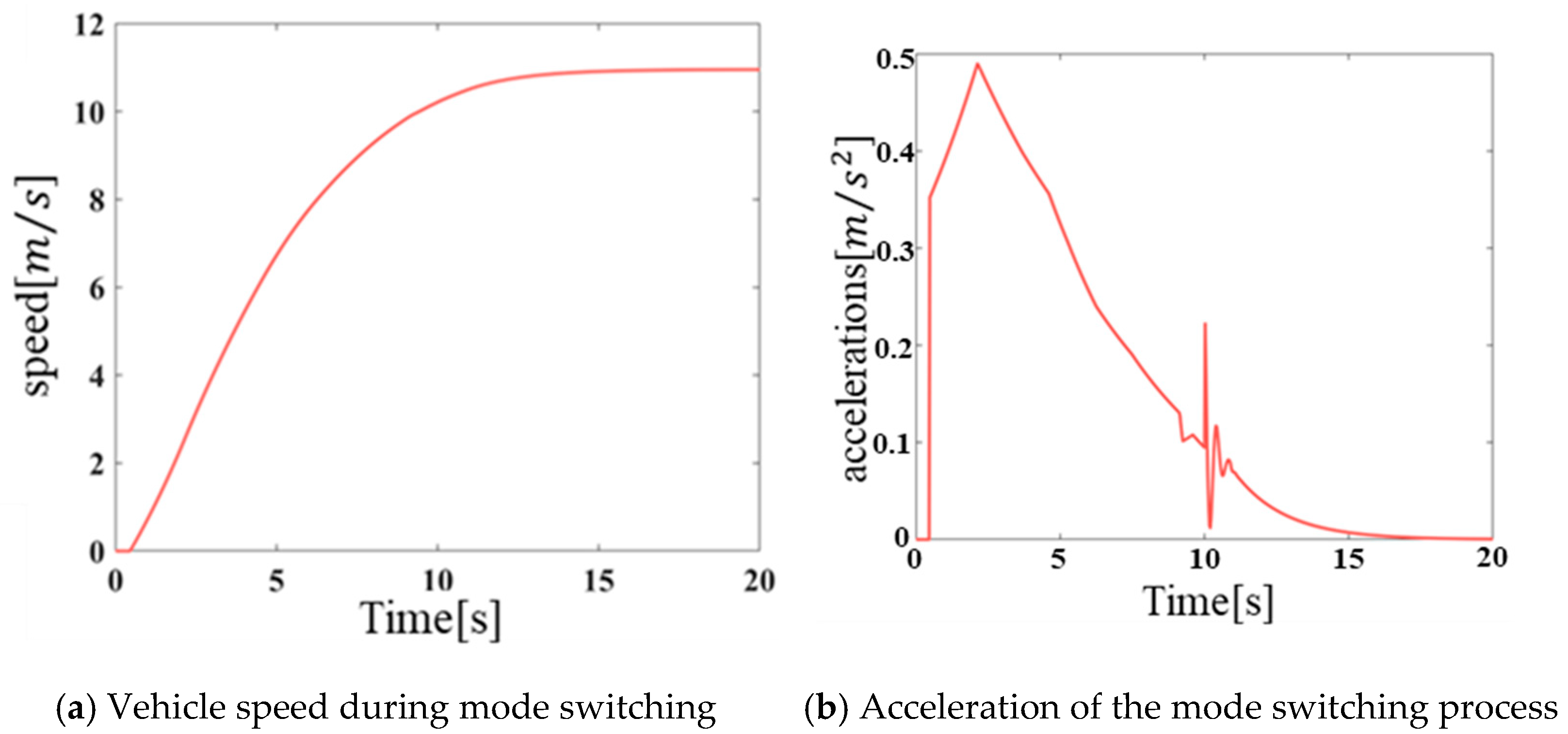
Figure 8, the speed and acceleration of the hybrid mining dump truck during the entire simulation process are relatively smooth, As shown in
Figure 8b, torque fluctuations and jumps occur during the clutch switching process at 10 s. According to international standards for mechanical vibration and passenger comfort, the peak acceleration must be less than 3.5
; the acceleration changes during the mode switching process are within a reasonable range, thereby meeting the performance requirements of the vehicle.
In summary, the impact and sliding power generated by HMPC during the mode switching process of hybrid mining dump trucks were reduced compared to those generated by MPC, but are slightly higher than that generated by extensible control. However, the simulation time of HMPC decreased by about 35% compared to that under extensible control and by about 27% compared to that under MPC. The reduction in simulation time indicates that HMPC significantly reduces algorithm complexity through the compact expression of the MLD model and the mixed integer optimization pruning strategy. This creates computational resource redundancy for handling more complex multi-mode hybrid systems. HMPC can significantly shorten simulation times while improving vehicle smoothness and reducing sliding friction during mode switching.
6. Conclusions
Hybrid transmissions are a hybrid process with clutches in different operating modes during mode switching. This paper provides a detailed description of the classification of different hybrid system models. The hybrid logic dynamic model integrates continuous and discrete variables, thereby facilitating a more comprehensive description of the system’s behavior. Consequently, the MLD model is selected to represent the hybrid component of mode switching, encompassing the definition of system variables and parameters, auxiliary variables, continuous variables to update the equations, and the subsequent utilization of HYSDEL to construct the standard MLD model.
In consideration of the hybrid characteristics of the hybrid drivetrain during the mode switching process, the established MLD model of the hybrid system is utilized as a prediction model in the MPC algorithm to optimize the mode switching process. The established hybrid model predictive controller is simulated, and different prediction time domains are selected to simulate the mode switching process of the hybrid mining dump truck. The speed tracking effect of brake BR1 under different prediction time domains is compared to obtain the optimal prediction time domain. An analysis of the performance of the mode switching process reveals that the vehicle’s impact during mode switching, as determined by the high-order Markov process model (HMPC), is less than 15 . Additionally, the slip work is approximately 19,000 J. It is observed that the simulation time is reduced by approximately 27% in comparison with that under MPC, and by approximately 35% in comparison with that under topological control.
Therefore, the HMPC algorithm has the potential to enhance the real time of the control process, thereby improving the system’s adaptability to varying working conditions and demand changes. The HMPC framework is based on hybrid system modeling, decoupling the continuous dynamics and discrete logic of the dynamical system. This modular design enables it to flexibly adapt to hybrid power systems of different configurations. It reduces the real time and enhances the robustness of the control process, and is more suitable for mode switching in hybrid drivetrains.
In the current research, the proposed hybrid model predictive control strategy has shown certain advantages in the mode switching control of hybrid mining dump trucks, but further analysis is needed in terms of uncertainty propagation. The hydraulic system and vehicle dynamics parameters are affected by multiple factors and have uncertainty, but the effects of load changes and sensor measurement noise interference have not been fully studied. After considering the propagation of these uncertainties, further research is needed on the trade-off between real-time performance and robustness, as well as the adaptability of HMPC strategies to multi-mode switching scenarios.


