Article

Stiffness Optimization for Hybrid Electric Vehicle Powertrain Mounting System in the Context of NSGA II for Vibration Decoupling and Dynamic Reaction Minimization

1
School of Mechanical and Electrical Engineering, Zhengzhou University of Light Industry, Zhengzhou 450002, China
2
Henan Hengfa Technology Co., Ltd., Xinxiang 453400, China
*
Author to whom correspondence should be addressed.
World Electr. Veh. J. 2025, 16(3), 131; https://doi.org/10.3390/wevj16030131
Submission received: 2 January 2025 / Revised: 21 February 2025 / Accepted: 25 February 2025 / Published: 27 February 2025

Abstract

:
In order to solve the problem of the insufficient vibration isolation performance of passenger cars in the suspension matching process, the six-degree-of-freedom (6-DOF) model, including three translational (x, y, z) and three rotational (roll, pitch, yaw) degrees of freedom, is established to comprehensively analyze the dynamic behavior of the powertrain mounting system. A 6-DOF dynamic model was established to analyze the decoupling rate and frequency distribution in its inherent characteristics, calculate the dynamic reaction of the suspension system, set the decoupling rate and the dynamic reaction of the suspension as optimization objectives, and use the NSGA II (Non-dominated Sorting Genetic Algorithm II) optimization algorithm to optimize the stiffness of the suspension. The 6-DOF decoupling of the whole suspension system is optimized and the dynamic reaction transmitted to the body is minimized. At the same time, this ensures that each suspension has enough static load support stiffness, and that its static deformation and amplitude are within the limit allowed under various working conditions, avoiding premature fatigue damage. The vibration isolation capability of the optimized system has been significantly improved, and the centroid acceleration has been significantly reduced under start–stop and road excitation conditions. The optimization method was effectively verified. Compared with existing studies focusing on single-objective optimization, the proposed NSGA II-based approach achieves a 93.4% decoupling rate in the critical Rx direction (vs. 59% pre-optimization) and reduces dynamic reaction forces by 8.3% (from 193 N to 177 N), demonstrating superior engineering applicability compared with traditional methods. Finally, the robustness analysis of the optimized stiffness met the requirements of production and manufacturing, indicating that the improvement of the decoupling rate of the suspension system and the optimization of the dynamic reaction force can effectively improve the vibration isolation performance, thereby improving the ride comfort of the vehicle.

1. Introduction

The NVH (noise, vibration, harshness) performance of a vehicle has an important impact on the ride comfort and market competitiveness of the vehicle [1]. As one of the main vibration sources of the vehicle, the excitation generated in the working process of the powertrain is transmitted to the body through the suspension system, and then it causes structural vibration and interior noise [2,3]. Therefore, the design of the mounting system plays a crucial role in the optimization of the vibration isolation performance of the powertrain. The powertrain mounting system not only needs to support and limit the powertrain, but also needs to have a good vibration isolation effect to reduce the transmission of engine vibration to the body [4]. However, under conditions such as frequent engine start–stop and complex road excitation, the vibration transmission is still high, which seriously affects ride comfort [5]. Therefore, the research on the optimal design of the powertrain mounting system has important engineering application value.
At present, for the optimization design of the automotive powertrain mounting system, domestic and foreign scholars have proposed a variety of methods, mainly including the energy decoupling method [6,7], Torque Roll Axis decoupling method [8,9,10], and optimization method based on vibration response or support reaction minimization [11]. Among them, the energy decoupling method is usually combined with the natural frequency of the suspension system to further improve the vibration isolation performance of the system. Shangguan Wenbin et al. introduced the concept of the torque axis and established the vibration equation of the suspension system in the torque axis coordinate system [12]. Shen et al. adopted the energy decoupling method to optimize the design of the powertrain mounting system [13]. Tang et al. took the decoupling rate and natural frequency distribution as optimization objectives and used the genetic algorithm to optimize the stiffness of the suspension system [14]. Based on the application of the energy decoupling method, Huijie et al. further improved the vibration isolation performance of the suspension system by rationally distributing the natural frequency of the system [15]. Fan et al. applied mathematical optimization technology for the first time in the design of the suspension system, selecting the natural frequency and modal decoupling rate of the suspension system as the objective function, and the stiffness and installation position as the design variables. The optimization design results significantly reduced the vibration coupling degree between each degree of freedom. At the same time, this ensured that the natural frequency distribution was within the expected range [16].
In addition, Liu et al. studied the powertrain mounting system under idle conditions, and effectively reduced the degree of vibration transmission to the body by optimizing the mounting position of the mounting system. They proposed that the engine idling excitation frequency should be less than 2 times the first-order bending mode frequency of the body, and that the lower the value, the better [17]. Jeong et al. proposed the minimum response design method, which broke the traditional idea of targeting the rigid body mode of the powertrain, and optimized the mounting parameters by minimizing the response force at the mounting point and the vibration response at the seat under idle conditions [18,19]. Tang et al. focused on the decoupling design of the powertrain suspension system, and significantly improved the vibration decoupling performance of the powertrain by optimizing the mounting position of the suspension system [20]. Liang et al. [21] further proposed a suspension optimization strategy that is closer to engineering applications, and extra consideration was given to the maximum allowable deformation of the powertrain under static or quasi-static forces, thus improving the reliability of the design of the suspension system. Xin et al. established a 6-DOF dynamics model based on large passenger cars, optimized the position of the engine mount through decoupling technology and transmission force minimization, and significantly reduced the vibration level of vehicles [22]. Mo et al. further discussed the influence of frame flexibility on suspension performance, and quantitatively analyzed the contribution of the frame or subframe flexibility mode to powertrain dynamic response by using finite element analysis and experimental modal testing [23]. Traditional optimization methods are unable to satisfy various objective functions well and lack robust analysis of optimized parameters. Therefore, the NSGA II method is adopted in this paper for multi-objective optimization, which is a more efficient approach than the traditional algorithm, and the optimization design results are compared with those obtained before optimization.
Based on the above research status, this paper takes the powertrain mounting system as the research object, proposes a multi-objective optimization design method, comprehensively considers the vibration and noise performance requirements, and improves the vibration isolation performance of the whole system by optimizing the stiffness value of the mounting system. Compared to existing studies focusing on single-objective optimization or limited decoupling directions, this work proposes a novel multi-objective framework combining NSGA II with robustness analysis. The proposed method achieves a 93.4% decoupling rate in the critical Rx direction (vs. 59% pre-optimization) and reduces the dynamic reaction forces by 8.3% (from 193 N to 177 N), demonstrating superior engineering applicability. Unlike previous studies that primarily focused on single-direction decoupling or static stiffness adjustments, this work introduces a comprehensive approach that simultaneously optimizes six degrees of freedom and integrates Monte Carlo-based robustness validation, ensuring both performance improvement and practical applicability in the context of real-world uncertainties.

2. Performance Analysis of Powertrain Mounting System

2.1. Dynamic Modeling

In order to further study the inherent characteristics of the powertrain mounting system of hybrid electric vehicles and analyze its vibration response characteristics under transient conditions (such as engine start–stop) and steady-state conditions (such as road excitation), so as to improve the vibration isolation performance of the whole vehicle, this paper regards the powertrain as a rigid body and establishes a 6-degree-of-freedom dynamic model. Compared with common 2-DOF or 3-DOF models, 6-DOF models can more comprehensively describe the motion state of the powertrain in space, including three translation directions (longitudinal, transverse, and vertical) and three rotation directions (roll, pitch, and yaw). This modeling method is of great significance for accurately reflecting the vibration transmission characteristics between the powertrain and the vehicle body under actual working conditions.
In this paper, the vibration differential equation of the system is derived by Lagrange method, the translation and rotation displacement of the powertrain are selected as generalized coordinates, and the generalized force expression of the system is constructed by considering the elastic force, damping force, and external exciting force. Based on this model, the following three aspects of research are carried out in this paper: (1) intrinsic characteristic analysis, which involves identifying the resonant frequency range of the system; (2) transient response analysis, which is carried out to evaluate the dynamic response of the engine under conditions such as start and stop; and (3) steady-state response analysis, in which the vibration isolation performance under steady-state conditions such as road excitation is studied.
On this basis, by optimizing the stiffness and damping parameters of the suspension system, the vibration isolation effect of the system is improved. The introduction of the 6-DOF model not only improves the accuracy of the system analysis, but also captures the multidimensional vibration behavior of the powertrain under complex excitation conditions, so as to provide more comprehensive data support and a theoretical basis for the optimal design of the suspension system.
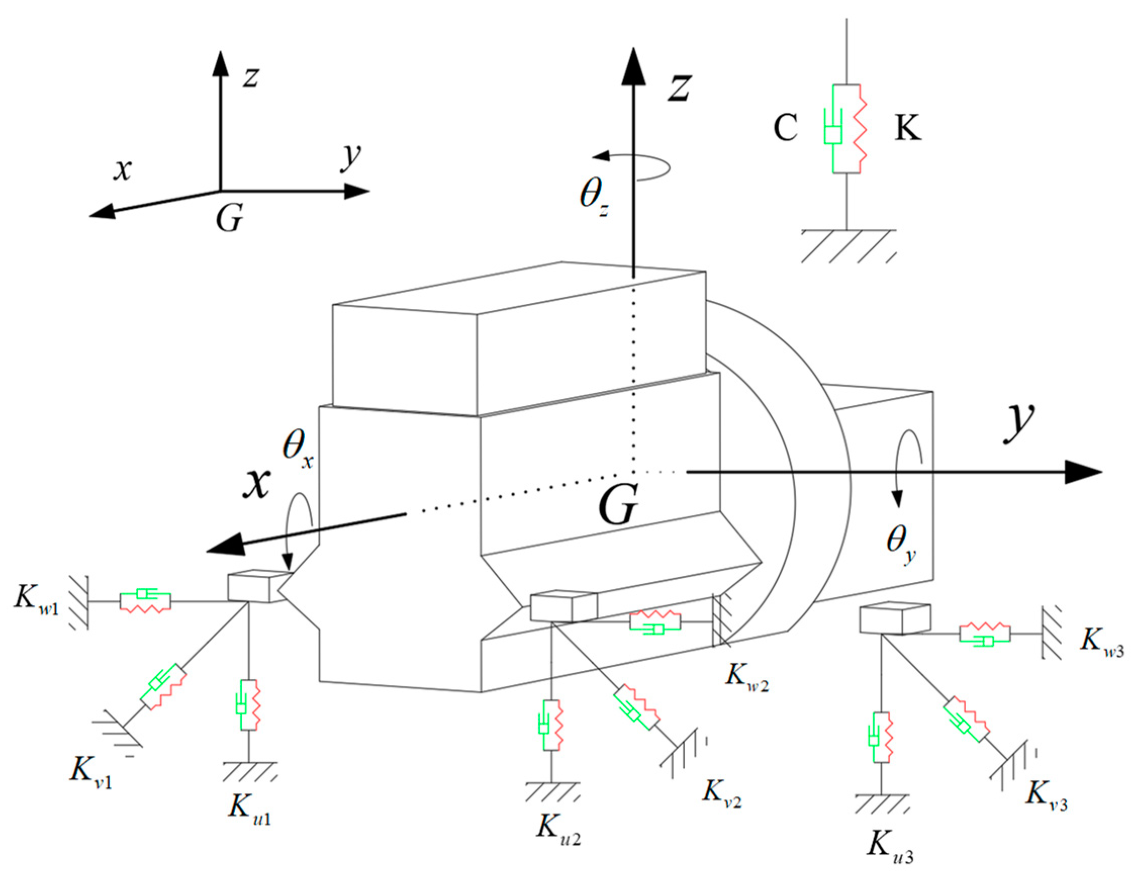
The powertrain mounting system usually adopts a 3-point arrangement or a 4-point arrangement, and the engine layout is divided into two types: horizontal and vertical. The suspension system studied in this paper is a 3-point horizontal arrangement. Since the vibration natural frequency of the powertrain mounting system is generally lower than 30 Hz, the engine and transmission assembly and the frame are usually regarded as absolute rigid bodies, and each mounting is simplified into elastic damping elements in three vertical directions along the space, ignoring the torsional elastic effect between the support elements. Therefore, the powertrain mount system can be equivalent to a spatial 6-DOF vibration system, as shown in Figure 1, below.
In this system, the origin represents the position of the center of mass of the powertrain at rest. The associated parameters Kui, Kvi, and Kwi for the ith suspension represent the spindle stiffness corresponding to the u, v, and w directions of the elastic spindle of the rubber suspension, respectively. The freedom of motion of a rigid body consists of three linear displacements (longitudinal x, transverse y, vertical z) and rotations around three axes (roll angle θ x pitch angle θ y , and yaw angle θ z ).
Let the generalized displacement vector of the powertrain mounting system be q :
q = x y z θ x θ y θ z T
The generalized displacement vector q includes three translational displacements (Cartesian coordinates x , y , z ) and three rotational angles (Euler angles θ x , θ y , θ z ), representing the rigid-body motion of the powertrain in 6-DOF space [22].
The vibration equation of the powertrain mounting system is
M q ¨ + C q ˙ + K q = F t
where M is the system mass matrix; C is the system damping matrix; K is the stiffness matrix of the system. The mass matrix M and damping matrix C are constant under small vibration assumptions, while the stiffness matrix K is the primary optimization variable. F ( t ) is the exciting force; q ¨ = ( x ¨ , y ¨ , z ¨ , θ x , θ y , θ z ) T is six generalized acceleration vectors. The vector q ( t ) explicitly depends on time t, governed by the dynamic interaction between inertial, damping, and stiffness forces.
In the design of powertrain mounting systems, the installation position and angle are usually considered in the early stage of design, along with structural layout, manufacturing process, performance requirements, and other factors, so they are difficult to change significantly in practical engineering applications. Therefore, the optimal design of the suspension system mainly focuses on the adjustment of the stiffness matrix, and improves the vibration isolation performance of the system by changing the stiffness characteristics of the suspension. This method can not only effectively improve the decoupling degree of the system in theory, but also provide a feasible optimization scheme in engineering practice. Therefore, the stiffness matrix is derived in detail in order to realize vibration decoupling and performance optimization of the suspension system.

2.2. Derivation of Stiffness Matrix K

According to the mechanical analysis, after the suspension is moved and rotated, the values of the deformation caused by the stiffness direction of the three main axes of the ith suspension are Δ u i , Δ v i Δ w i . Consequently, the potential energy of the system on the elastic main axes u , v , w of the rubber suspension is
U = 1 2 i = 1 n K ω i Δ u i 2 + K i i Δ v i 2 + K w i Δ w i 2
Equation (3) is derived from the potential energy analysis of elastic deformation, following the Lagrangian mechanics principles [10]. The stiffness matrix formulation (Equation (5)) aligns with the methodology proposed by Hu et al. [10] for multi-axis decoupling.
Equation (3) is decomposed:
U = 1 2 q T i = 1 n E i T × B i T × D i × B i × E i q
Therefore, the stiffness matrix is
K = i = 1 n E i T × B i T × D i × B i × E
where D i K u i 0 0 0 K v i 0 0 0 K w i , E i 100 010 001   0 z i y i z i 0 y i y i x i 0 ,   x i , y i , z i , are the centroid coordinates; B i = c o s α 1 i c o s β 1 i c o s γ 1 i c o s α 2 i c o s β 2 i c o s γ 2 i c o s α 3 i c o s β 3 i c o s γ 3 i , α i ,   β i , γ i ( i = 1 ,   2 ,   3 ) , are the angle between the suspension elastic spindle coordinate system and the vehicle coordinate system. Matrix B i is the direction cosine matrix, where c o s α k i , c o s β k i , and c o s γ k i define the orientation of the i th mount’s elastic axes relative to the vehicle coordinate system.
Because adjusting the mounting position and angle usually involves high design and manufacturing costs, optimizing the stiffness of the suspension can be achieved by adjusting the material characteristics or the internal structure of the suspension without changing the existing structural layout. This method is not only low in cost, but also easy to implement, and has significant advantages in engineering applications. Therefore, the research focus of this paper is to improve the vibration isolation performance by optimizing the suspension stiffness parameters, so as to achieve significant improvement in the system performance.

2.3. Energy Decoupling Method

Energy decoupling is a widely used method in the design of mounting parameters. The method assumes that the system is in the state of small vibration (ignoring the damping effect), and optimizes the vibration isolation performance of the system through reasonable configuration of the stiffness matrix. The six-degree-of-freedom linear free vibration differential equation of powertrain mounting system can be expressed as
M q ¨ + K q = 0
Equation (2) describes the forced vibration of the system under general excitation, while Equation (6) focuses on free vibration analysis by omitting damping effects, which is essential for energy decoupling studies.
For Equation (6), let the theoretical solution be
q = X i sin ω i t + α
where   X i is the amplitude of the theoretical solution; α is the phase angle.
Bringing this into Equation (6), we can obtain
K X i = ω i 2 M X i
K ω 2 M = 0
where ω is the natural frequency of the system.
The circular frequency and mode of vibration of the suspension system can be obtained from Equation (7). When the suspension system vibrates at the i order, the percentage T p k i of the total energy of the suspension system distributed at the k generalized degrees of freedom (representing the degree of decoupling) is
T p k i = T k T m a x i = i = 1 6 φ i l φ i k m k l i = 1 6 i = 1 6 φ i l φ i k m k l × 100 %
where m k l is the k th column l element of [ M ] ; φ i is the i order principal mode of the system; ( φ i ) k and ( φ i ) l are the k th and l th elements of   φ i respectively.

2.4. Suspension Dynamic Reaction Calculation

The dynamic reaction force of the suspension system refers to the reaction force transmitted to the frame or body through the suspension system when the powertrain is vibrating or under external excitation. This force comes from the excitation force and torque generated by the engine during operation, and is transmitted to the frame or body by the suspension system. It is a direct response to the body imposed by the suspension system in the process of supporting and constraining the powertrain, and also a direct reflection of the vibration isolation and support performance of the suspension system. The magnitude and direction of the dynamic reaction directly affect the vibration comfort and driving stability of the vehicle body, so optimizing the dynamic reaction is an important step to improve the NVH performance of the vehicle in the design of the suspension system.
Under idle conditions, the vibration differential equation of the engine mounting system is as follows:
[ M ] q ¨ + [ C ] q ˙ + [ K ] q = F e
where F e represents the harmonic exciting force vector received by the system under idle conditions.
In the calculation process for suspension dynamic reaction and centroid acceleration, the system damping matrix has a great influence on the calculation results, which cannot be ignored.
The steady-state solution of the system under forced vibration is
q = [ K ] ω 2 [ M ] + j ω [ C ] 1 F e
The dynamic reaction { f i } transmitted by the i th suspension to the body can be expressed as
f i = [ k i ] [ k i ] [ r i ] q
where [ k i ] is the ith stiffness matrix suspended in the global coordinate system; [ r i ] is the antisymmetric matrix of the i th suspension position coordinates.
The sum of the dynamic reaction force transmitted by the suspension system to the body under idle condition is
F = i = 1 n f x i 2 + f y i 2 + f z i 2
where f x i , f y i , f z i   are the three components of the dynamic reaction of the i th suspension under idle conditions.

2.5. Natural Characteristic Calculation

The calculation of natural frequency and decoupling ratio of powertrain mounting system is based on the data for mounting stiffness, mounting angle, mounting position, and inertia parameters of powertrain. These key parameters can be obtained by relevant testing means, and the initial data are shown in Table 1, Table 2 and Table 3. In the test, the mounting angle of the suspension was 0°, and all three suspensions were placed horizontally. In addition, the powertrain suspension of the model studied in this paper is made of rubber material, and its stiffness/dynamic ratio is 1.4 [24].
According to the above theoretical calculation, the natural frequencies and decoupling rates of each order of the prime powertrain mounting system can be obtained, as shown in Table 4, below.
The data in Table 4 show that the decoupling rate of the prime powertrain mounting system in the X direction is only 77%, and the coupling with the Y direction is serious. The decoupling rate for Rx direction is only 59.1%, and the coupling with Rz direction is serious. The decoupling rate for Ry direction is only 75.2%, and the coupling with X direction is serious. The decoupling rate for Rz direction is only 55.4%, and the coupling with Rx direction is serious. Only the decoupling rates of Y and Z, which are 99.7% and 96.3%, meet the design requirements. According to the above analysis, the decoupling rate for the four directions in the original 6-DOF system is low, and there is serious coupling with other directions, which will lead to excessively wide resonance band and slow vibration energy attenuation, thus affecting the vibration isolation performance of the entire suspension system. Therefore, the original suspension system must be optimized.

3. Optimal Design

3.1. Optimization Variable

In order to reduce the resonance band of the powertrain mounting system and reduce the dynamic force transmitted by the engine to the frame through the mounting system, the optimization objective of this study was to decouple and minimize the dynamic force transmitted to the body by the 6-DOF. The input excitation form of dynamic reaction is sine wave, whose frequency is equal to the idle frequency of the engine, and acts on the rotational freedom of the torque shaft of the powertrain, so as to more accurately simulate the vibration force transmitted by the powertrain to the body under the idling condition of the engine.
Although the decoupling rate of the suspension system in the main direction (Z direction) and rotation direction (Ry direction) reached a relatively ideal level, the decoupling rate and vibration isolation performance in other directions still have large room for optimization. The stiffness of the mounting system is a key factor affecting the vibration and noise of the vehicle, and it determines the vibration isolation ability of the vibration transmission path. Since the mounting position and angle of the powertrain mount were fixed in the design stage, further changes may increase the design and manufacturing costs, so the anisotropic principal stiffness of the rubber mount k i ( i = 1 , 2 , , n ) is used as an optimization design variable, where n represents the value of suspension stiffness. For the three-point suspension layout, each suspension has stiffness in three directions, forming a total of nine design variables. By adjusting these nine design variables, we can optimize the vibration isolation performance of the mount system and reduce the transmission of vibration, which significantly improves the ride comfort and NVH performance of the vehicle.

3.2. Constraint Condition

The power of the model studied in this paper is always a hybrid engine. The speed of the engine under idle conditions is 1400 r/min, and the corresponding excitation frequency is 46.7 Hz. When the natural frequency of the system is less than 1/ 2 of the excitation frequency, the vibration isolation effect can be achieved, the lower limit should be above the tire frequency and between the frame mode frequencies, and the suspension cannot be too soft for the engine mounting system, which generally requires more than 4 Hz. Therefore, the natural frequency of the mounting system ranges from 4.00 to 17.00 Hz. The suspension system is arranged horizontally. In the vehicle coordinate system, the suspension rotates around the crankshaft in the R Y Y   direction, and the R Y Y direction and the Z direction are the key directions of the transverse TRA (torque roll axis) arrangement. Requirements: 8 Hz ≤ R Y Y   direction mode ≤ 12 Hz, 8 Hz ≤ Z direction mode ≤ 11 Hz.
The constraint function is
4.00 f i , i = 1 , 2 6 17.00 8.00 f z 11.00 8.00 f R Y Y 12.00
where f i is the first 6 mode frequencies of the suspension system, and f z and f r y y are the mode frequencies of the main direction, Z and R Y Y , respectively.
At the same time, the static load displacement of the suspension system is considered, because the static load is mainly borne by the left and right suspension, so the static load displacement of the left and right suspension is required to not exceed 6 mm.
U s t U s t m a x
where U s t is the static load displacement of suspension, and U s t m a x is the maximum static load displacement of suspension.

3.3. Optimization Objective

3.3.1. The Decoupling Rate Is the Largest

The objective function is to achieve the maximum decoupling rate of 6 degrees of freedom of the suspension system. The suspension system is optimized and the multi-objective optimization is transformed into single-objective optimization. The optimization objective function is
m i n g k i = i = 1 6 α i 1 T p i 2 , 0 < α i < 1
where g ( k i ) is the decoupled optimization objective function of the suspension system; T p i is the energy percentage on each degree of freedom; α i is the influence factor.

3.3.2. The Dynamic Reaction Is Minimal

Under idle conditions, the vibration differential equation of the engine mounting system is as follows:
M q ¨ + K q = F e
where F e is a simple harmonic exciting force vector.
The steady-state solution U of the system is
U = i n v ( K ω 2 M ) F e
The dynamic reaction f i transmitted by the i suspension to the body is
f i = k i k i r i U
where k i is the stiffness matrix of the i th suspension; r i is the antisymmetric matrix of the i th suspended position coordinates.
The total dynamic reaction F transmitted by the suspension system to the body under idle condition is
F = i = 1 n f x i 2 + f y i 2 + f z i 2
In the formula, f x i , f y i , f z i   are the 3 components of the i suspended dynamic reaction under idle condition, where the dynamic reaction components f x i , f y i , and f z i can be expressed in terms of suspension stiffness and displacement:
f x i = k x i Δ x i , f y i = k y i Δ y i , f z i = k z i Δ z i
The optimization objective is the minimum dynamic reaction F :
m i n F = m i n i = 1 n ( k x i Δ x i ) 2 + ( k y i Δ y i ) 2 + ( k z i Δ z i ) 2
The smaller the F -value, the better the vibration isolation performance of the suspension system. This optimization method does not impose specific numerical constraints on the stiffness, but only aims at reducing the transmitted dynamic reaction, so as to maximize the vibration isolation effect in the design.

3.4. NSGA II Optimization Algorithm

The energy decoupling and functional relationship between mathematical model and mounting parameters of automotive powertrain mounting system are complex, and there are many local optimal solutions. When solving this kind of problem, the traditional algorithm easily falls into the local optimal solution, but the optimization process is stagnant, and NSGA II algorithm can solve this problem well. Its characteristics include non-dominant sorting, congestion calculation, elite strategy, etc., and its advantages are reflected in the need for no preset weight, good convergence and diversity, and strong adaptability and expansibility. It is an efficient, stable, and widely used multi-objective optimization algorithm, especially suitable for multi-objective and multi-constraint complex optimization problems. Moreover, the optimization calculation is carried out while taking into account the calculation efficiency, which greatly improves the optimization efficiency.
The second generation of non-inferior sorting genetic algorithm (NSGA II) is an efficient multi-objective optimization algorithm, which is widely used in various complex optimization problems. By using this algorithm to optimize the dynamic stiffness of three-point suspension with 6 degrees of freedom, the diversity and convergence of optimization results can be ensured effectively. The optimization process is shown in Figure 2.
NSGA II (non-dominated sorting genetic algorithm) is widely used in solving multi-objective uncertain optimization problems. Its core mechanism includes non-dominated sorting and congestion calculation, which are used to cross, mutate, and iteratively obtain Pareto solution set. The Pareto solution set is shown in Figure 3.
In particular, fast non-dominated sorting divides populations by goals to form Pareto frontiers, while the optimal populations form the final Pareto solution set. The aim of the crowding calculation is to evaluate the distribution of solution sets by measuring the distance between adjacent solutions, and then determine the priority of individual selection.
This adaptive adjustment mechanism can flexibly adjust the intensity of crossover and variation according to the change of population congestion, enhance the global search ability of the algorithm, improve the convergence speed of local optimal solutions, and ensure the diversity and accuracy of Pareto solution set.

4. Comparison Before and After Optimization

4.1. Decoupling Rate Comparison

Table 5 shows the comparison of the stiffness of each suspension before and after optimization.
The data in Table 6 and Table 7 show that the X-direction decoupling rate increased from 76.9% to 96.9% after optimization. The RX direction decoupling rate increased from 59% to 93.4%. The decoupling rate in the RY direction increased from 75.2% to 94%. The decoupling rate in the RZ direction increased from 55.4% to 87.8%, and the decoupling rates in the Y and Z directions were basically unchanged, meeting the actual requirements of the project. The decoupling rate of the powertrain mounting system greatly improved after the genetic algorithm optimization, effectively shortening the resonance band and making the vibration energy decay rapidly. The total dynamic reaction was also reduced, from 193 N to 177 N, and the vibration isolation performance improved.

4.2. Frequency Response Comparison

In hybrid models, start–stop conditions and road excitation conditions are the key conditions to evaluate the performance of the powertrain mount system. Because the engine starts and stops frequently, the vibration caused by the transient excitation is relatively strong, and these vibrations are easily transmitted to the body through the mounting system, consequently affecting the ride comfort and noise, vibration, and comfort (NVH) performance of the vehicle. Especially at the moment of start and stop, the acceleration of the powertrain centroid changes greatly, which requires the mounting system to have higher dynamic vibration isolation performance to effectively inhibit the transmission of bad vibration. On the other hand, the road excitation condition reflects the vibration encountered by the vehicle in the actual driving process. Random vertical vibration excitation may cause coupling vibration between the powertrain and the body structure, which also poses an important test to the vibration isolation performance of the suspension system.
The torque around the crankshaft torsion direction was applied to the powertrain to stimulate 100 N·m, and the powertrain translation and rotation amplitude–frequency characteristics were obtained, as shown in Figure 4 and Figure 5 [7].
In this paper, a simulation analysis was carried out under these two working conditions. The acceleration response amplitude diagram of the system at different frequencies shows the acceleration response of the mounting system to different excitation frequencies in the frequency range of 0–30 Hz, which is used to analyze the vibration isolation characteristics of the system in the low-frequency band. In the 6-DOF acceleration frequency domain analysis diagram of the powertrain centroid position under start–stop conditions, the acceleration response of the powertrain in the 6-DOF (three translation, three rotation) direction under start–stop conditions is compared and analyzed, and the dynamic vibration isolation performance and optimization effect of the system under transient excitation are evaluated. The comparison diagram for the two working conditions before and after optimization is as follows:
The amplitude approaches zero at low frequencies (0–5 Hz) due to the system’s natural frequency range (4–17 Hz), where vibration isolation becomes effective when the excitation frequencies exceed 2 times the natural frequency.
Through NSGA II optimization, the NVH performance of the suspension system is effectively improved with the goal of maximizing the decoupling rate. Based on the input torque of 100 N in the simulation model, the acceleration response of the powertrain centroid is judged to determine the optimization effect. Under the transient start–stop torque excitation condition, the powertrain mass center X, Y, Z translational acceleration peak value ranges from 0.71 m/s, 0.025 m/s, and 0.067 m/s to 0.08 m/s, 0.11 m/s, and 0.017 m/s. The peak rotational acceleration values of the powertrain center of mass, RX, RY, and RZ, decreased from 0.92 m/s, 7.2 m/s, and 1.34 m/s to 0.38 m/s, 3.45 m/s, and 0.57 m/s, respectively. Both the translational acceleration and the angular displacement acceleration were effectively reduced, and the overall NVH performance of the vehicle was improved.

4.3. Robustness Analysis

Robustness analysis plays a key role in the optimization of the suspension system. Its purpose is to evaluate the impact of the suspension parameters on the vibration isolation performance of the system when there are uncertainties in the actual working conditions (such as manufacturing errors, material property fluctuations, and environmental changes). In this paper, the Monte Carlo method is used for the robustness analysis. By introducing random perturbations to key parameters such as suspension stiffness and calculating a large number of random simulation samples, the performance changes of the optimized suspension system under different disturbance conditions were statistically analyzed. This method can effectively evaluate the performance stability of the optimization scheme under uncertain factors, and ensure that the suspension system can maintain a high vibration isolation effect in the complex and changing actual use environment, so as to improve the reliability of the powertrain suspension system and the NVH performance of the vehicle.
The following table shows the normal distribution statistics for the energy decoupling of the optimized suspension system. In engineering design, it is generally required that the change rate of the objective function does not exceed 5%, that is, the ratio of standard deviation to the mean value should be less than 5%. In the randomized test 1000 of the optimized suspension system, the maximum change rate of the six-way decoupling rate was 4.98%, which meets the requirements of robustness. The Monte Carlo simulation (1000 samples) confirmed that the optimized system maintains a coefficient of variation below 5% for all decoupling rates (Table 8), ensuring robustness against manufacturing uncertainties.

5. Conclusions

This paper focuses on the optimization research on powertrain rubber mounting systems for hybrid electric vehicles.
(1) Aiming at the lack of vibration isolation performance of the suspension system, a six-degree-of-freedom dynamic model of the suspension system was established, and the decoupling rate and dynamic reaction were taken as the optimization objectives.
(2) By adjusting the suspension stiffness, the vibration isolation performance and vibration decoupling effect of the system were improved. Before optimization, the decoupling rate of the system was 59%, and after optimization, it increased to 93.4%. The dynamic reaction decreased from 193 N to 177 N. Next, the Monte Carlo method was used to analyze the robustness of the optimized mounting system, and its stability in the actual manufacturing and use environment was verified.
(3) MATLAB2023b programming was used to apply road excitation and start–stop excitation in the torsion direction around the crankshaft to the model to investigate the translational center of mass and angular acceleration of the powertrain before and after optimization. The experimental results show that the optimized suspension system reduces the vibration transmitted by the powertrain to the body and improves the NVH performance of the whole vehicle.
This study provides an effective optimization method and a theoretical basis for the design of a hybrid vehicle suspension system by applying a multi-objective optimization algorithm.

Author Contributions

Z.F., Conceptualization and Methodolog; Q.L., Writing—original draft; L.Y., Writing—review & editing; X.H., Project administration and Funding acquisition. All authors have read and agreed to the published version of the manuscript.

Funding

This research is supported by Science and Technique Research Project of Henan Province (Grant No. 222102240116), the Plan of Key Research Projects of Higher Education of Henan Province (Grant No. 24A460024), and the Science and Technology Open Cooperation Project of Henan Academy of Sciences (Grant No. 220907016). These financial supports are gratefully acknowledged.

Institutional Review Board Statement

Not applicable.

Informed Consent Statement

Not applicable.

Data Availability Statement

The original contributions presented in this study are included in the article. Further inquiries can be directed to the corresponding author.

Conflicts of Interest

Xiaojuan Hu is an employee of Henan Hengfa Technology Co., Ltd. The remaining authors declare that the research was conducted in the absence of any commercial or financial relationships that could be construed as a potential conflict of interest.

References

  1. Shui, Y.; Wen, H.; Zhao, J.; Wu, Y.; Huang, H. Optimization of Vehicle Powertrain Mounting System Based on Generalized Inverse Cascade Method under Uncertainty. Appl. Sci. 2023, 13, 7615. [Google Scholar] [CrossRef]
  2. Wu, Y.; Zhao, D.; Peng, J.; Xiang, X.; Huang, H. Hybrid Electric Vehicle Powertrain Mounting System Optimization Based on Cross-Industry Standard Process for Data Mining. Electronics 2024, 13, 1117. [Google Scholar] [CrossRef]
  3. Zhou, H.; Liu, H.; Gao, P.; Xiang, C.-L. Optimization design and performance analysis of vehicle powertrain mounting system. Chin. J. Mech. Eng. 2018, 31, 31. [Google Scholar] [CrossRef]
  4. Cai, B.; Shangguan, W.B.; Lü, H. An efficient analysis and optimization method for the powertrain mounting system with hybrid random and interval uncertainties. Eng. Optim. 2019, 52, 1522–1541. [Google Scholar] [CrossRef]
  5. Xu, X.; Su, C.; Dong, P.; Liu, Y.; Wang, S. Optimization design of powertrain mounting system considering vibration analysis of multi-excitation. Adv. Mech. Eng. 2018, 10, 1687814018788246. [Google Scholar] [CrossRef]
  6. Guo, R.; Gao, J.; Wei, X. Influence of hydraulic engine mounts on engine shake based on full vehicle model. Vibroeng. Procedia 2016, 10, 376–381. [Google Scholar]
  7. Le, V.Q. Comparing the performance of suspension system of semi-trailer truck with two air suspension systems. Vibroeng. Procedia 2017, 14, 220–226. [Google Scholar] [CrossRef]
  8. Le, X.L.; Le, V.Q.; Bui, V.C. Study on the influence of bus suspension parameters on ride comfort. Vibroeng. Procedia 2018, 21, 77–82. [Google Scholar]
  9. Zheng, L.-F.; Wang, T.; Li, G.-X. Vibration and noise analysis of heavy-duty trucks based on powertrain lightweighting. J. Vibroeng. 2017, 19, 4573–4590. [Google Scholar] [CrossRef]
  10. Hu, J.F.; Singh, R. Improved torque roll axis decoupling axiom for a powertrain mounting system in the presence of a compliant base. J. Sound Vib. 2012, 331, 1498–1518. [Google Scholar] [CrossRef]
  11. Kolte, S.U.; Neihguk, D.; Prasad, A.; Rawte, S.; Gondhalekar, A. A Particle Swarm Optimization Tool for Decoupling Automotive Powertrain Torque Roll Axis; SAE Technical Paper; SAE International: Warrendale, PA, USA, 2014. [Google Scholar]
  12. Duan, X.W.; Li, Y.N.; Zhang, L.; Deng, Z.X. Multi-objective optimization for a MR engine mount based on NSGA II algorithm. Zhendong Yu Chongji/J. Vib. Shock 2014, 33, 191–196+202. [Google Scholar]
  13. Shen, B.S.; Zhang, M.J.; Jin, J.J. Optimization of a commercial vehicle powertrain mounting system based on new rubber mounts. J. Vibroeng. 2024, 26, 383–400. [Google Scholar] [CrossRef]
  14. Tang, X.; Wang, P.; Zhou, X. Optimization of a commercial vehicle powertrain mount system. J. Vib. Wave 2021, 100, 24. [Google Scholar]
  15. Huijie, Z.; Huirong, H.; Zhiping, G. Analysis and optimization design of six degrees of freedom engine mount system. J. Vib. Eng. 2019, 32, 801–810. [Google Scholar]
  16. Fan, R.-L.; Zhang, C.-Y.; Fei, Z.-N.; Qu, S.-J.; Shao, J.-Y.; Song, P.-J. Equivalent Stiffness and Equivalent Position for Torque Strut Mount in Powertrain Mounting System. SAE Int. J. Engines 2018, 11, 311–320. [Google Scholar] [CrossRef]
  17. Liu, Q.; Bai, G.D.; Liu, Z.H.; Bai, X.X.; Du, H.; Chen, P.; Qian, L.J. Magnetorheological semi-active mount system for engines: Prototyping and testing. Proc. Inst. Mech. Eng. Part D J. Automob. Eng. 2020, 234, 3081–3094. [Google Scholar] [CrossRef]
  18. Endur, P.; Tun, B. Design sensitivity and optimization of powertrain mount system design parameters for rigid body modes and kinetic energy distributions. J. Braz. Soc. Mech. Sci. Eng. 2020, 42, 486. [Google Scholar] [CrossRef]
  19. Jeong, T.; Singh, R. Analytical Methods of Decoupling the Automotive Engine Torque Roll Axis. J. Sound Vib. 2000, 234, 85–114. [Google Scholar] [CrossRef]
  20. Tang, X.; Zhang, D.; Liu, T.; Khajepour, A.; Yu, H.; Wang, H. Research on the energy control of a dual-motor hybrid vehicle during engine start-stop process. Energy 2019, 166, 1181–1193. [Google Scholar] [CrossRef]
  21. Liang, J.; Zhang, D.; Wang, S. Vibration characteristic analysis of single-cylinder two-stroke engine and mounting system optimization design. Sci. Prog. 2020, 103, 0036850420930631. [Google Scholar] [CrossRef] [PubMed]
  22. Xin, F.-L.; Qian, L.-J.; Du, H.-P.; Li, W.-H. Multi-objective robust optimization design for powertrain mount system of electric vehicles. J. Low Freq. Noise Vib. Act. Control 2017, 36, 243–260. [Google Scholar] [CrossRef]
  23. Mo, S.; Chen, K.; Zhang, Y.; Zhou, Y.; Lyu, L.; Yao, B.; Zhang, W. Research on Rigid-Flexible Coupling Nonlinear Dynamics of Light Commercial Vehicle Considering Frame Flexibility. Int. J. Non-Linear Mech. 2025, 170, 104949. [Google Scholar] [CrossRef]
  24. Chen, L.; Bao, Y.; Pan, X.; Duan, X. Editing method for accelerative fatigue test spectrum of a rubber isolator. J. Vib. Shock 2012, 17, 12–16. [Google Scholar]
Figure 1. Dynamics model of powertrain mounting system.
Wevj 16 00131 g001
Figure 2. NSGAII optimization algorithm flow.
Wevj 16 00131 g002
Figure 3. Pareto solution set.
Wevj 16 00131 g003
Figure 4. Optimized front and rear powertrain centroid translational acceleration under start–stop excitation.
Wevj 16 00131 g004
Figure 5. Optimized front and rear powertrain centroid rotation acceleration under start–stop excitation.
Wevj 16 00131 g005
Table 1. Spindle stiffness of suspension system.
Stiffness Dynamic Stiffness (N/mm) Static Stiffness (N/mm)
XYZXYZ
Left mounting2807328020052200
Right mounting2808629820061.4213
Down mounting213132141529410
Table 2. Inertia parameters of powertrain mounting system.
Quality m/kg J x x J y y J z z J x y J y z J z x Unit
247.01718.41810.08616.779−1.874−0.147−0.296kg·m2
Table 3. Powertrain mount elastic center coordinates.
StiffnessXYZMounting Angle
Left mounting−151.5−486.2282.2
Right mounting−261.3492.9265.7
Down mounting13.86−75.88−231.96
Table 4. Mount system natural frequency and decoupling rate.
Mounting System 6 Degrees of FreedomXYZ R X X R Y Y R Z Z
Modal distribution (Hz)8.12145.41957.635815.210310.941314.6211
Decoupling rate/%76.98200.02281.42290.598219.73781.2363
0.029599.71980.00570.15650.02350.0649
2.22660.007196.36760.67370.06430.6606
0.12880.02171.129759.09940.401239.2192
20.4744−0.00021.0642−0.158275.24283.3769
0.15870.22870.009839.63034.530455.4421
Total dynamic reaction (N)193
Table 5. Stiffness comparison between front and rear suspension before and after optimization.
Suspension StiffnessRaw Stiffness (N/mm)Optimal Stiffness (N/mm)
k u 1 280227
k v 1 7368
k w 1 280334
k u 2 280224
k v 2 8680
k w 2 298238
k u 3 213253
k v 3 132122
k w 3 1412
Table 6. Optimization of the natural frequency and decoupling ratio of the rear mount system.
Mounting System Six Degrees of FreedomXYZ R X X R Y Y R Z Z
Modal distribution (Hz)8.12145.41957.635815.210310.941314.6211
Decoupling rate/%96.97260.01920.05570.05491.55571.3420
0.033299.65310.00010.06990.02360.2201
0.08980.000199.66970.02400.21610.0003
−0.00820.01560.035293.36730.11666.4735
2.10390.00100.2374−0.403893.91364.1479
0.80860.31110.00206.88774.174487.8162
Total dynamic reaction (N)177
Table 7. Decoupling rate comparison.
The Number of Modal OrdersVibration DirectionEnergy Distribution/(%)
Before optimizationPost-optimization
1X76.996.9
2Y99.799.7
3Z96.399.6
4RX5993.4
5RY75.294
6RZ55.487.8
Table 8. Normal distribution statistics of energy decoupling rate of suspension system.
Decoupling DirectionExEyEzErxEryErz
Mean value96.5899.5798.4693.0892.1789.54
Standard deviation2.031.743.184.644.554.03
Coefficient of variation2.10%1.75%3.23%4.98%4.93%4.50%
Disclaimer/Publisher’s Note: The statements, opinions and data contained in all publications are solely those of the individual author(s) and contributor(s) and not of MDPI and/or the editor(s). MDPI and/or the editor(s) disclaim responsibility for any injury to people or property resulting from any ideas, methods, instructions or products referred to in the content.

