1. Introduction
In order to solve the problem that electric forklifts are prone to rollover when turning, a coordinated control strategy for anti-rollover of electric forklifts was proposed. Forklifts have short wheelbases and short track widths, large steering wheel turning angles, and their center of mass position is constantly changing due to the load being handled, making them prone to rollover accidents. Forklift accidents caused by forklift rollovers account for as much as 42% [
1]. Therefore, it is particularly important to study the anti-rollover control of forklifts.
In recent years, experts and scholars have conducted in-depth research on the lateral stability and rollover prevention control of road vehicles. However, there are relatively few studies on the rollover prevention control of forklifts. Therefore, analyzing the rollover stability and rollover prevention control strategy of road vehicles has important reference significance for research on the rollover prevention control of forklifts. Ghazali [
2] used model predictive control to design active steering anti-rollover and path-following integrated control, effectively solving the multi-objective constraint optimization problem, aiming to reduce the vehicle’s lateral acceleration and improve the vehicle’s lateral stability. Termous [
3] proposed an anti-rollover coordinated control strategy based on the coordination among active steering, differential braking and active suspension systems. When the controller detects the risk of rollover, the proposed control strategy can effectively reduce the risk of rollover. Akar [
4] focused on how the lateral load transfer rate (LTR) as a rollover factor reflects the tendency of a vehicle to roll over during vehicle driving. Considering the time-varying nature and limitations of the traditional lateral load transfer rate (LTR), Zong C [
5] proposed a dynamic LTR bus anti-rollover control strategy based on the three-degree-of-freedom model of the bus, which effectively improved the rollover stability of the bus. Qi B [
6] proposed a vehicle stability evaluation index by calculating the vehicle instability energy threshold and the vehicle’s real-time instability energy and designed a differential drive sliding mode controller to greatly improve the active safety of electric vehicles. Zhang L [
7] analyzed the instability mechanism of hub motor vehicles and proposed a chassis coordinated control method for body yaw and roll stability that integrates differential drive, active steering and active suspension to improve the vehicle’s lateral stability control effect.
As to how to effectively improve the lateral stability of forklifts, researchers have conducted some research on forklift anti-rollover. RINCHI [
8] established an electric forklift model based on MATLAB 2022a/Simulink and estimated the center of gravity of the forklift loaded with goods through load sensors and ramp recognition sensors to determine whether the projection of the center of gravity on the driving plane is within the safe area. The stability of the forklift is ensured by limiting the maximum speed and acceleration of the electric wheel. Felez [
9] studied the pitch motion of an automatically guided forklift to analyze the stability conditions of the vehicle and designed an anti-rollover controller based on model predictive control, but it is unknown whether it is applicable to counterbalanced forklifts. Rebelle [
10] established a dynamic model of a forklift and verified the model. They used the model to analyze the common and critical driving situations of a forklift in a rollover accident. Tao [
11] proposed a lateral stability control system with the forklift’s sideslip angle and yaw angular velocity as the desired control targets, adopted a drive torque coordinated distribution control strategy, and solved the forklift’s steering stability problem caused by lateral local loads. Xia G [
12] proposed a rollover prevention hierarchical control method based on a T-S fuzzy neural network, which used a neural network to judge the motion state of the forklift and controlled it based on the lateral load transfer rate (LTR). Kasahara [
13] studied the effect of changes in the center of gravity on the roll of a forklift, designed a test model with a measurable center of gravity, and studied the lateral stability of the forklift when turning by calculating the LTR. Zhang Z [
14] considered the influence of cargo lifting on the synthetic center of gravity during the forklift turning process, and established a vehicle model including cargo weight and cargo-lifting speed. Based on this model, a lateral stability controller based on a simplified chaotic particle swarm algorithm was designed, and active steering and differential braking were used to jointly control the forklift. Xia G [
15] analyzed the motion state of all-terrain forklifts on different road surfaces, proposed the roll stability indices HR-LTR and SR-LTR considering different road surfaces, and established an anti-roll control strategy based on road surface recognition. Zhang Y [
16] studied the influence of forklift structural parameters and road roughness excitation on forklift roll dynamics and discussed the rationality of evaluating the vehicle roll state by LTR.
Among the existing rollover prevention control strategies, the lateral load transfer rate is a commonly used indicator for judging vehicle stability. It has the characteristics of high real-time performance and strong universality, but its value is affected by the accuracy of sensor measurement and there is no clear standard for determining the threshold [
17,
18,
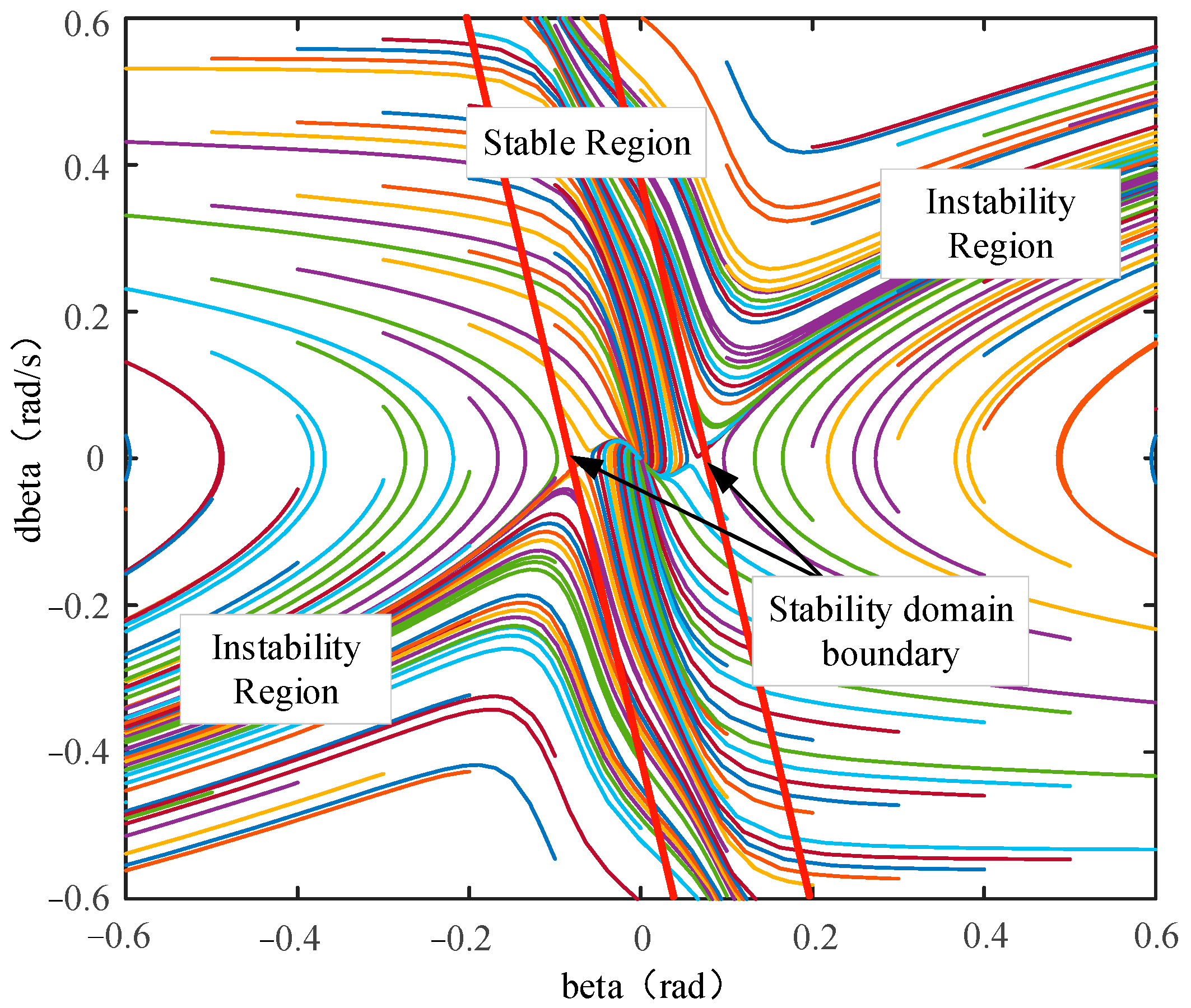
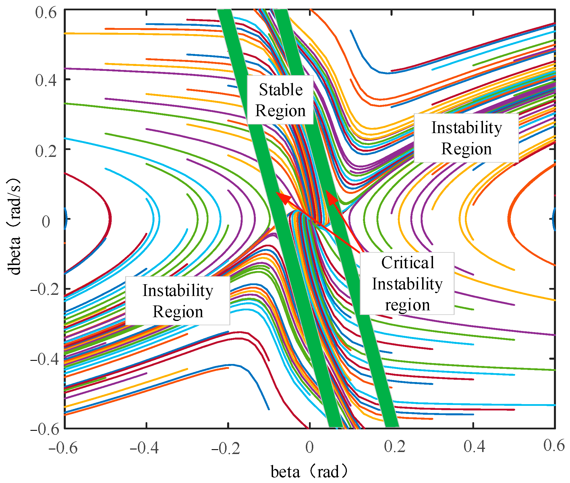
19]. The phase plane method is less affected by the accuracy of sensor measurement and does not need to consider the threshold value. It can judge the stability of the forklift more accurately [
20]. In order to further improve the stability of electric forklifts, in addition to relying on accurate judgment of forklift stability, anti-rollover control methods must be adopted, such as anti-rollover cylinders, active steering and differential braking. Anti-rollover cylinders have good control effects, but the forklift structure is complex and difficult to control [
21]. Active steering improves vehicle stability by applying additional steering angles to the steering wheels, but the control function will fail when the tire lateral force is saturated. Differential braking uses the tire longitudinal force to generate additional yaw torque to improve vehicle stability under extreme conditions, but it will affect the driving speed [
22]. Active steering and differential braking coordinated control can reasonably and fully utilize tire lateral force and longitudinal force, combining the advantages of both to achieve vehicle stability control. In the anti-rollover coordinated control strategy of electric forklifts, the phase plane area division method is adopted to solve the problem of forklift stability judgment; considering the problem that active steering and differential braking are insufficient to control separately, an active steering and differential braking coordinated control strategy is designed. Finally, the effectiveness of this control strategy is verified by simulation.
The main contributions of this paper include:
- (1)
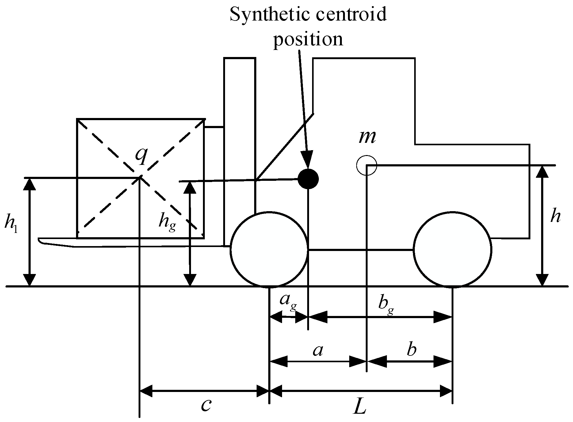
In order to explore the impact of cargo on the forklift’s center of mass, a synthetic center of mass position model was constructed.
- (2)
In order to judge the stability of forklifts, the phase plane area division method was adopted.
- (3)
Considering the problem of insufficient control of active steering and differential braking alone, a coordinated control strategy of active steering and differential braking was designed.
4. Rollover Prevention Coordinated Control Strategy
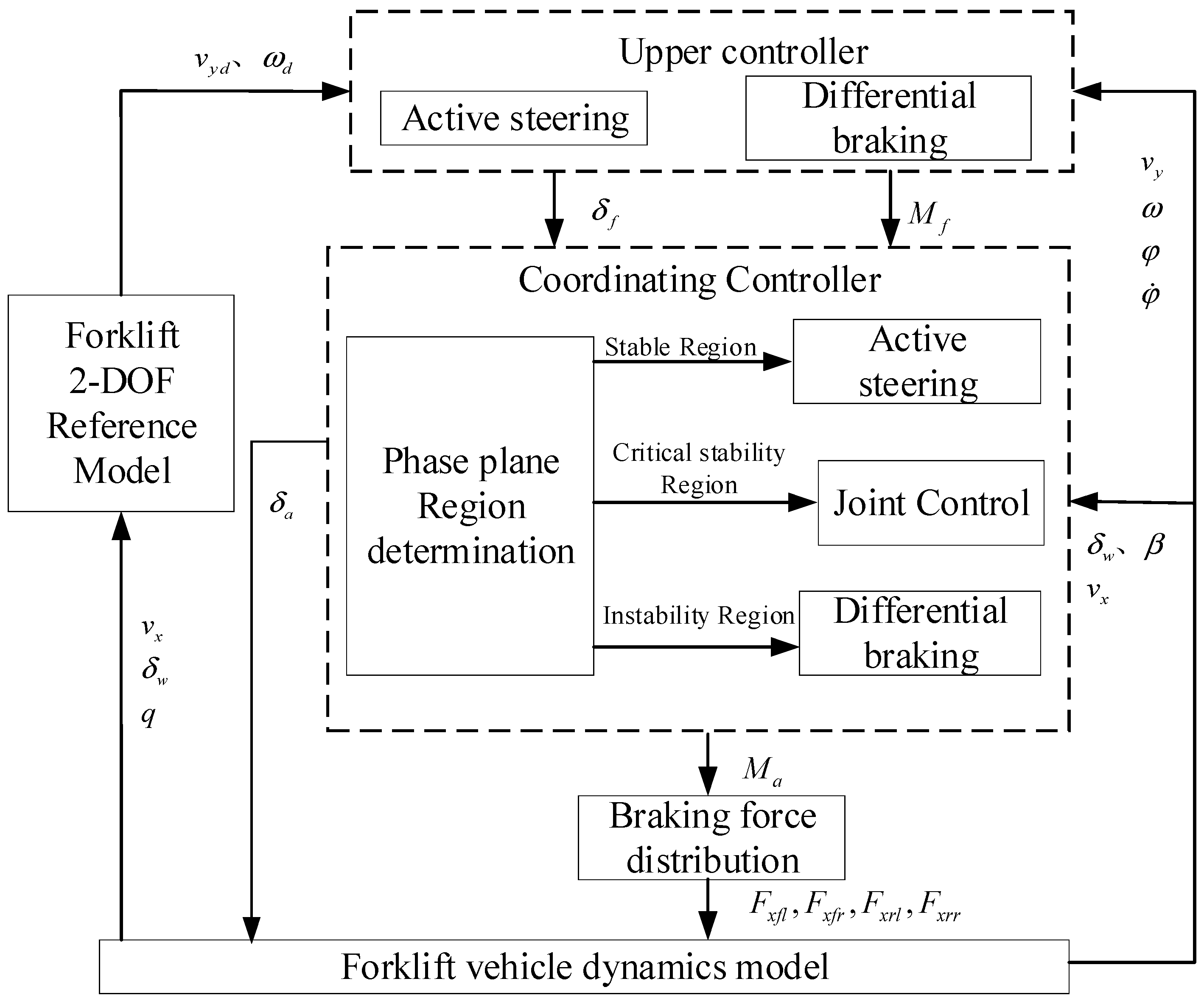
The anti-rollover coordinated control strategy for electric forklifts consists of an upper controller, a coordinated controller, and a braking force distribution controller, and the structure is shown in
Figure 8. The rear wheel steering angle, current vehicle speed, and cargo mass information are calculated by the two-degree-of-freedom model of the forklift to obtain the expected yaw rate and center of mass slip angle. The active steering fuzzy PID controller in the upper controller determines the additional rear wheel steering angle based on the difference between the body roll angle and the expected value and its rate of change; the differential braking MPC controller makes the actual center of mass slip angle, yaw rate, and body roll angle change with the expected value to determine the required additional yaw moment. Then, the coordinated controller determines the control weight coefficients of the active steering controller and the differential braking controller in different control domains. In the stable domain, active steering control is adopted; in the critical stability domain, active steering and differential braking joint control are adopted, and as the degree of instability of the forklift increases, the weight coefficient of the differential braking control action gradually increases; in the instability domain, only differential braking control is adopted. The braking force distribution controller applies braking force to different wheels according to the additional yaw moment to improve the anti-rollover ability of the forklift when turning.
4.1. Upper Controller
The upper controller consists of two parts: the active steering fuzzy PID controller determines the additional rear wheel steering angle, and the differential braking MPC controller determines the additional yaw moment.
4.1.1. Active Steering Fuzzy PID Controller
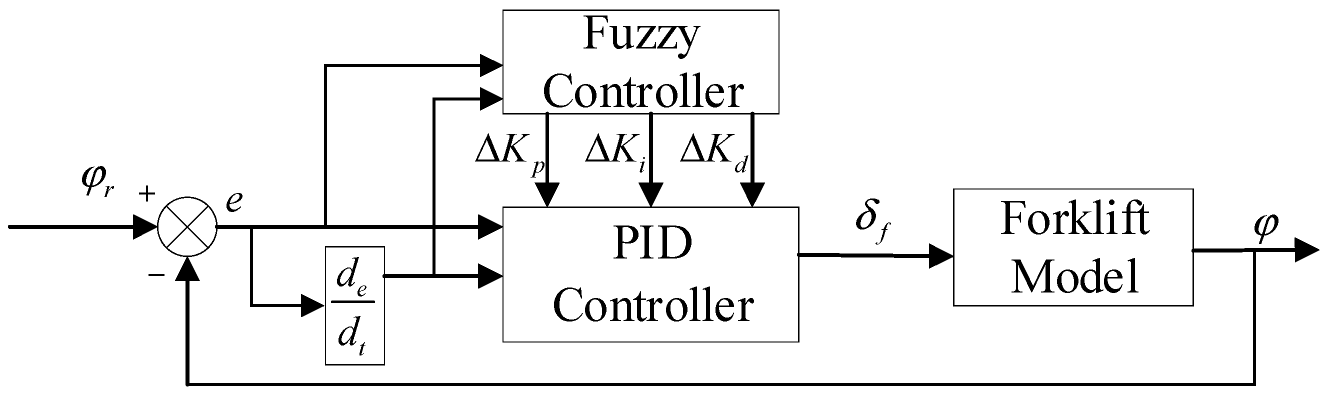
The fuzzy PID algorithm has good robustness and does not rely on mathematical models. Fuzzy rules designed based on expert experience can achieve good control effects. The difference
e in the expected value of the body roll angle and the difference change rate
ec are used as the input of the fuzzy PID controller, and the active steering rear wheel angle is used as the output. The control structure of the fuzzy PID is shown in
Figure 9. The PID controller parameters
are adjusted according to the results of fuzzy reasoning. The parameter values of the PID controller are determined as 300, 14, and 10, through simulation experiments.
The domain of error
e and the error change rate
ec is set to [−3,3]. The fuzzy quantities corresponding to the input changes
e and
ec are
E and
EC, and the fuzzy subsets are {NB, NM, NS, ZO, PS, PM, PB}. The definitions of each element of the fuzzy subset are NB (negative large), NM (negative medium), NS (negative small), ZO (almost zero), PS (positive small), PM (positive medium), and PB (positive large). Δ
Kp, Δ
Ki, Δ
Kd domains are set to [−3,3], [−6,6] and [−1,1], respectively, and the fuzzy subsets are {NB,NM,NS,ZO,PS,PM,PB}.
Table 2 is the fuzzy rule table.
4.1.2. Differential Braking MPC Controller
MPC is a commonly used optimal control method, particularly suitable for solving optimization problems with constraints. It can optimize the control law in real time to adapt to the dynamic change. In vehicle control, state constraints and actuator constraints are often present, making MPC widely used in vehicle stability control [
27].
According to the forklift vehicle model, the state variable
is selected, the control variable
, and the forklift model without control is obtained as follows:
For the convenience of writing, let
,
; then, the following formula is obtained:
The state equation of the forklift with differential braking control can be expressed as follows:
Subtracting Equations (27) and (31) above, we obtain the state equation:
Simplifying Equation (32), we can obtain the forklift state space equation used for model predictive control:
Discretization is performed to obtain the state space equation of the discrete state:
where
;
;
;
k is the current sampling time;
k + 1 is the next sampling time; I is the unit matrix;
is the sampling period.
When performing model predictive control, we hope that the controlled output is infinitely close to the expected value. Therefore, the control increment can be used as the state quantity of the objective function, and the objective function can be written as follows:
where
is the control output prediction sequence;
is the control output reference sequence;
is the output error and control increment error weight matrix;
is the predict the value at time k + i based on the sampling information at time
k;
is the control amount and control increment at time
k + i.In control, it is necessary to add constraints to the control quantity, control increment and output quantity:
Considering the system constraints, the following optimization problem is solved in each step:
4.2. Coordinating Controller
In order to achieve a good control effect and ensure the coordinated operation of the two controllers, the weight coefficient is introduced to control the two controllers. In the stable domain, due to the small yaw moment required, active steering control is adopted to ensure the driving speed of the forklift. In the critical stable domain, active steering and differential braking are used for joint control. As the instability of the forklift increases, the weight coefficient of differential braking control gradually increases. At this time, in the unstable domain, a large yaw moment is required to ensure the safe driving of the vehicle. Only differential braking control is used. At this time, the relationship between the differential braking weight coefficient and the control area is shown in
Figure 10.
According to the above analysis, the additional rear wheel steering angle and additional yaw moment after coordinated control distribution can be obtained as follows:
4.3. Brake Force Distributor
The additional yaw moment is independent of the lateral force of the braked wheel and is only generated by the wheel braking force. Therefore, a braking force distribution controller is needed to distribute the braking force required by each wheel, correct the forklift posture, and improve the forklift stability [
28]. The selection rules for the differential brake wheel are shown in
Table 3.
If the two wheels on the right side of the forklift are braked, according to
Figure 3, the following is obtained:
where
represent the braking force of the right front and rear wheels, respectively.
When the wheel is not locked, the wheel braking force is approximately proportional to its vertical load. In order to make full use of the road adhesion conditions, the braking force can be dynamically distributed in real time according to the following formula.
Similarly, the braking force on the left wheel is also distributed in the above manner.
5. Simulation Analysis
In order to verify the effectiveness of this control strategy for forklift anti-rollover control, a Matlab/Simulink simulation model was built with a 3T electric forklift as a reference. The main parameters of electric forklifts are shown in
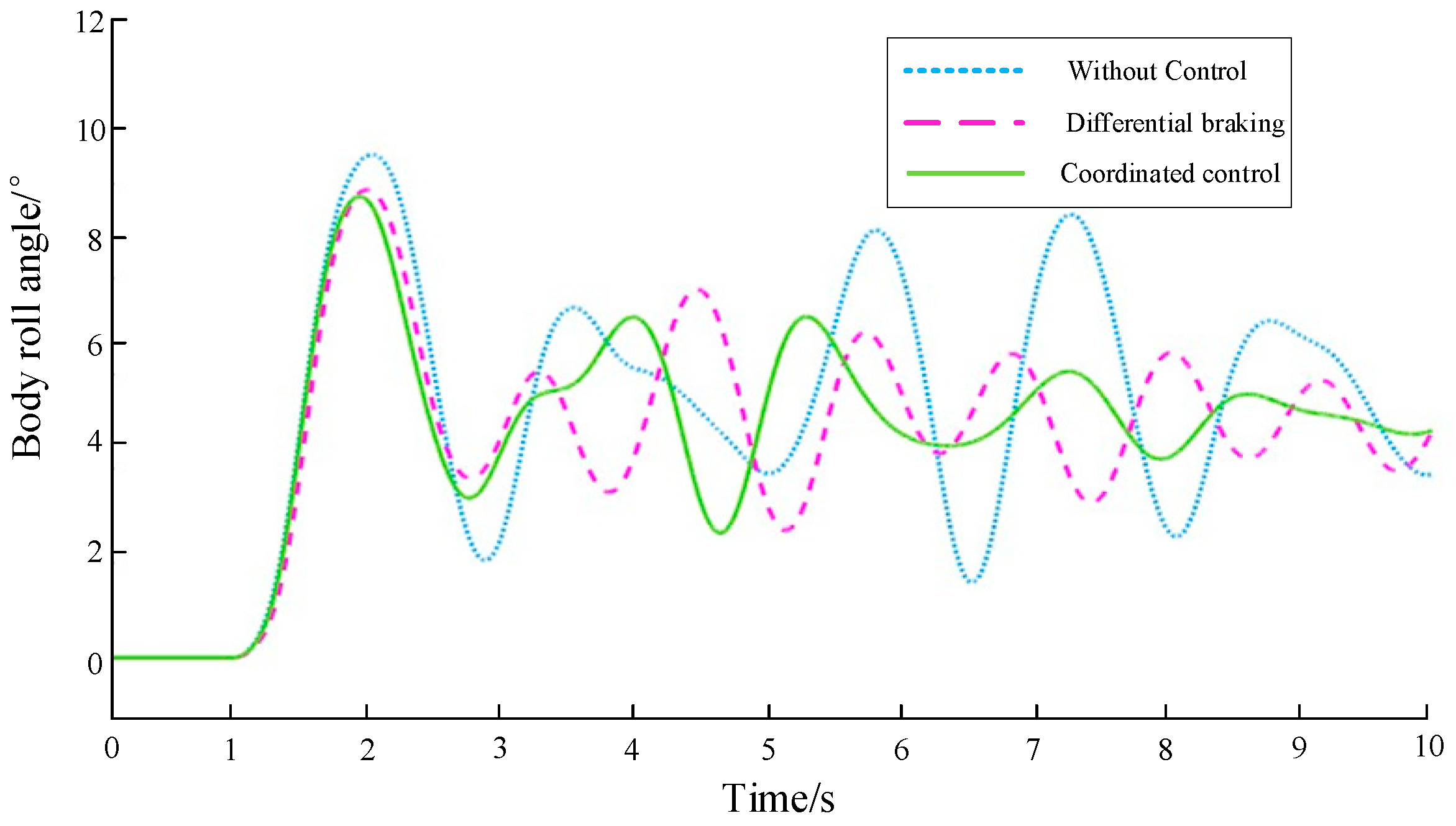
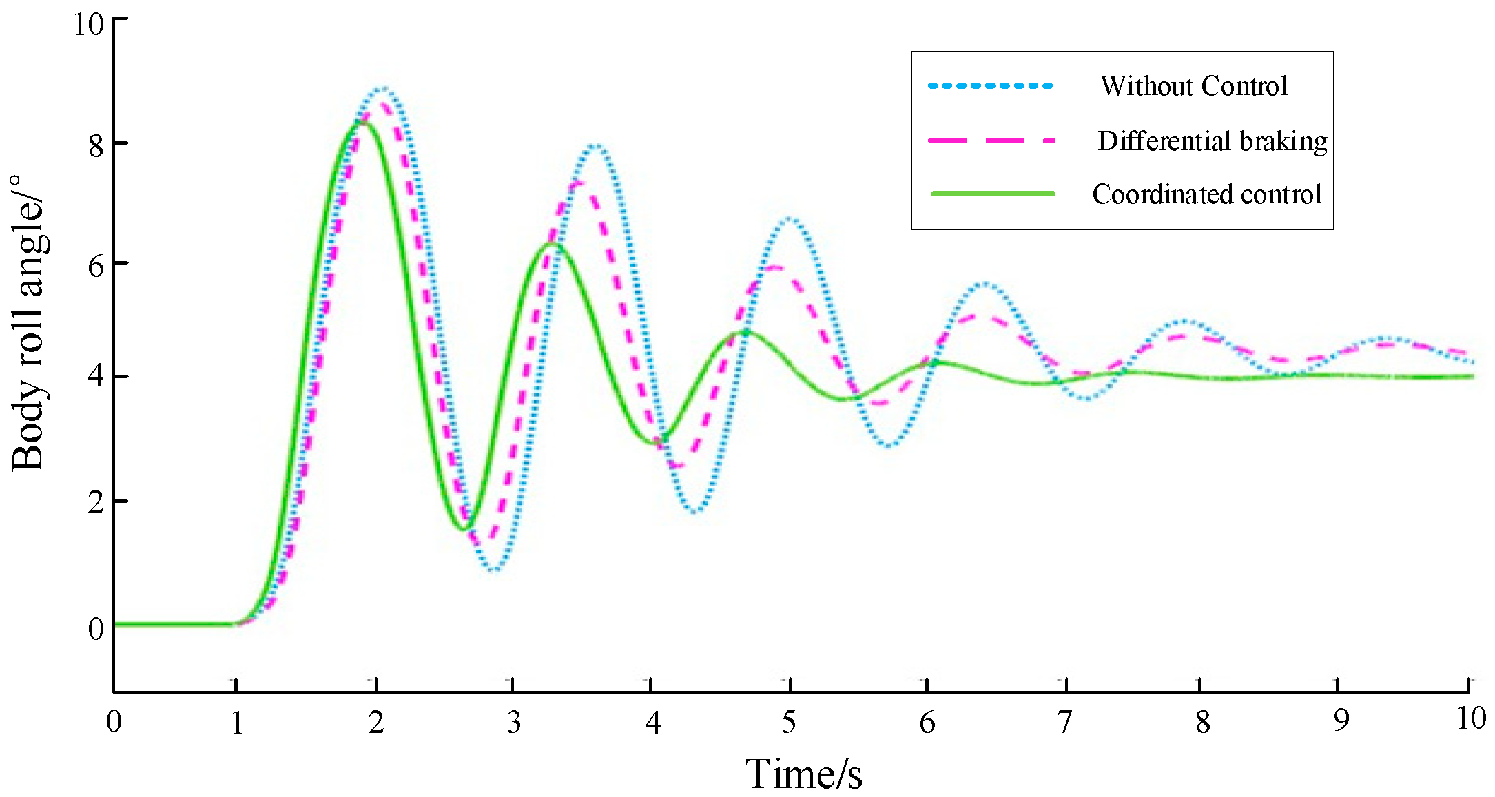
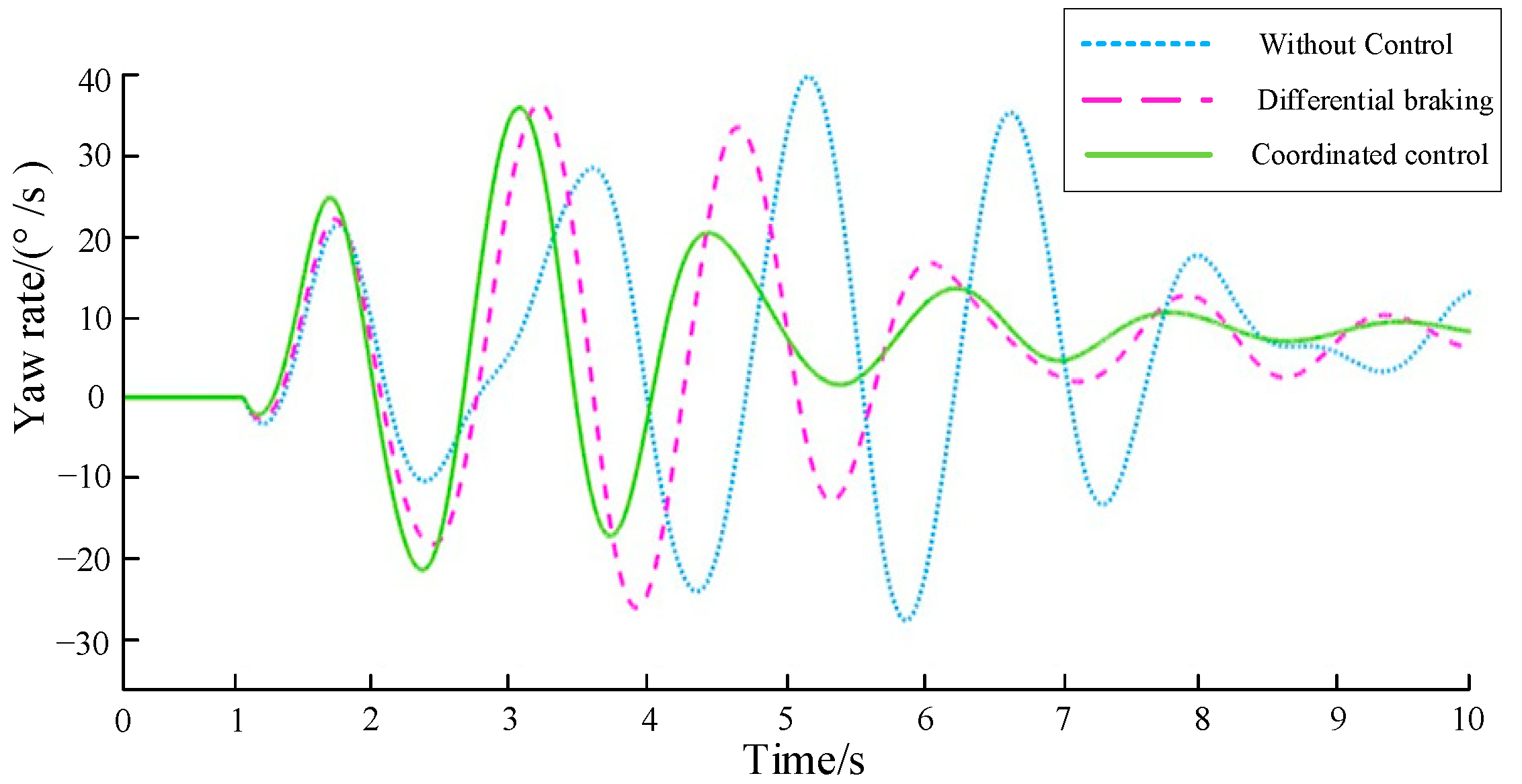
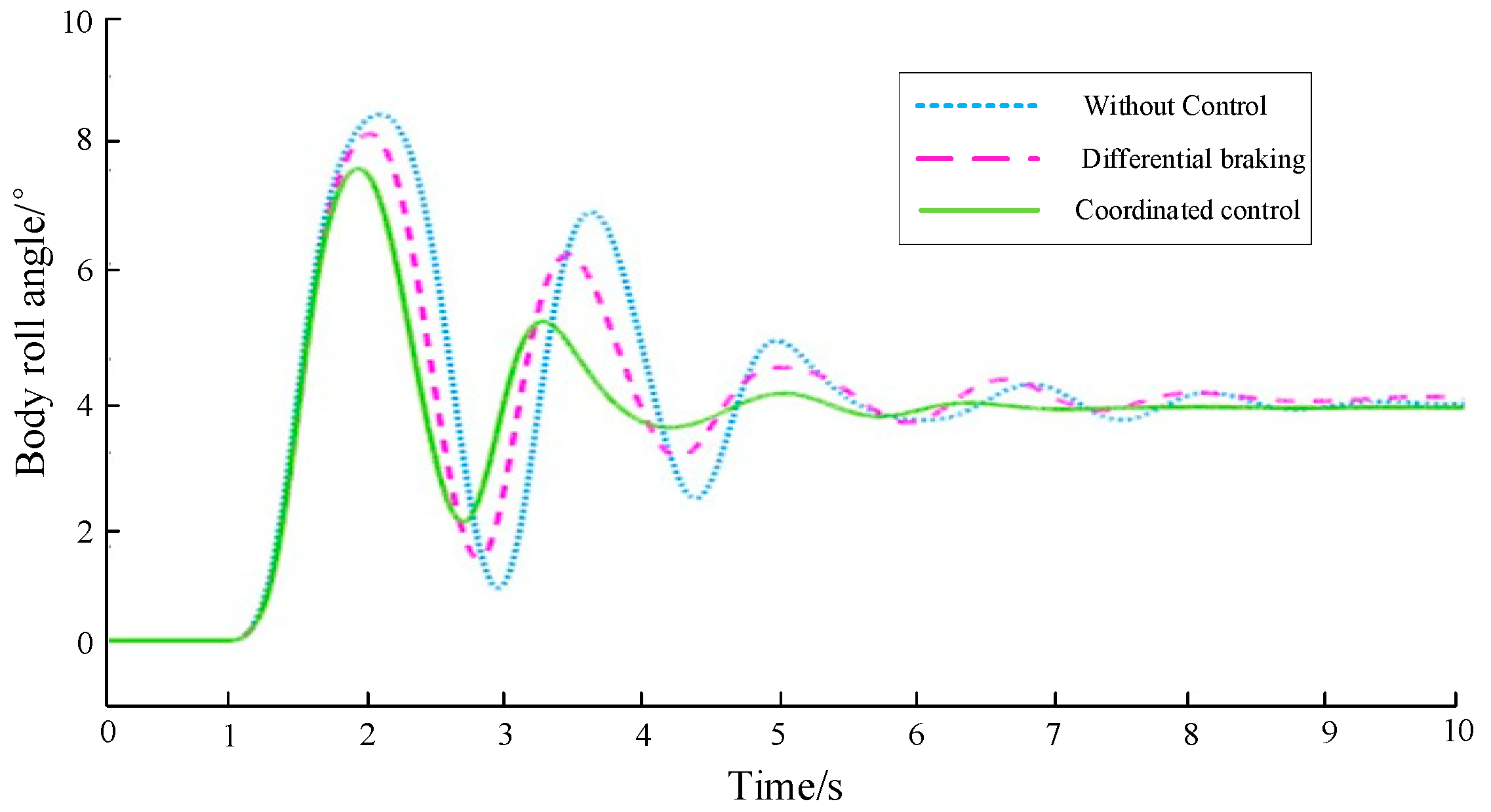
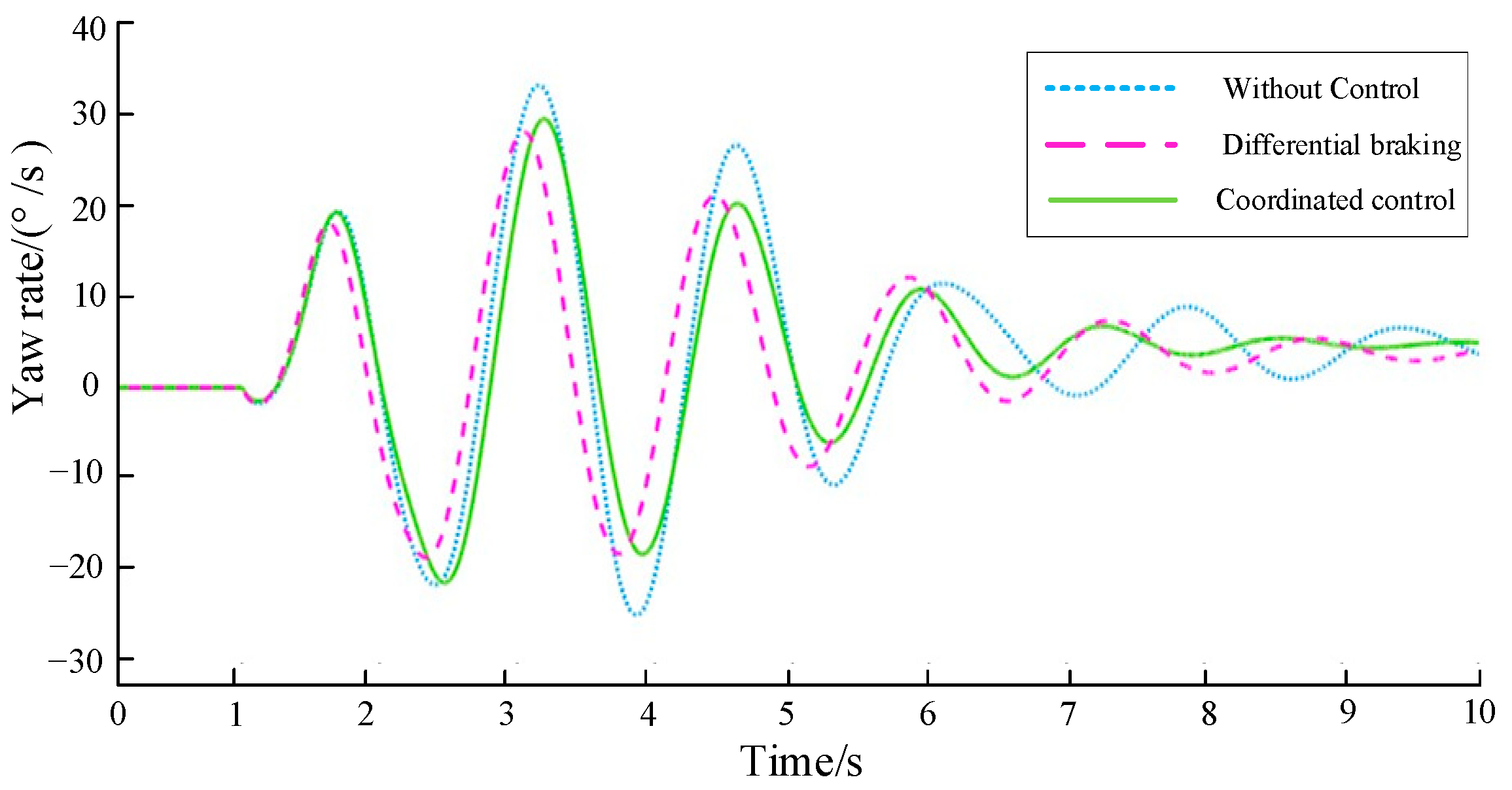
Table 4. Using the typical working condition of angular step steering, the steering wheel was turned from the initial state of 0° to 250° at a constant speed within 1 s. The forklift speed was 15 km/h. The three states of the forklift, namely, empty, half-loaded, and fully loaded, were analyzed, and the roll angle and yaw angular velocity of the forklift body were compared under no control, differential braking control, and coordinated control. The simulation results are shown in
Figure 11,
Figure 12,
Figure 13,
Figure 14,
Figure 15 and
Figure 16. At the same time, the peak value and stable time are compared and analyzed, as shown in
Table 5,
Table 6,
Table 7 and
Table 8.
Through simulation analysis, it can be seen that, under no-load conditions, when there is no control, the roll angle and yaw rate of the forklift body increase sharply, and are in a large-amplitude oscillation state without a trend of stabilization. Under differential braking control and coordinated control, the fluctuation in these two parameters is significantly reduced. In particular, the coordinated control has a better effect. The peak values of the body roll angle and yaw rate are controlled within 8.8° and 46°/s, with the maximum improvement of 11.7% and 26.1%, respectively, and the body roll angle and yaw rate quickly reach a stable state. Under half-load conditions, the peak values of the body roll angle and yaw rate under coordinated control are controlled within 8.2° and 35°/s, which is better than the no-control state and differential braking control, with the maximum improvement of 10.5% and 14.3%, respectively, and the maximum reduction in stabilization time is 30.3% and 22.4%, respectively. Under full-load conditions, the peak values of the body roll angle and yaw rate under coordinated control are controlled within 7.6° and 29°/s, with maximum improvements of 9.5% and 14.7%, respectively, and the maximum reductions in stabilization time are 33.5% and 20.2%, respectively. Although the yaw rate under coordinated control is slightly higher than that without control within 2 to 3 s, its peak value is still lower than that without control.
6. Conclusions
In the coordinated control strategy for electric forklift rollover prevention, the phase plane area division method is used to judge the stability of the forklift; considering the problem of insufficient control of active steering and differential braking alone, the coordinated control strategy of active steering and differential braking is designed. Taking a 3T electric forklift as a reference, a MATLAB/Simulink simulation model is built for verification. When unloaded, the peak values of the body roll angle and yaw angular velocity under coordinated control are reduced by 11.7% and 26.1%, respectively compared with those without control, and the stable state is reached quickly; when half-loaded, the peak values of the body roll angle and yaw angular velocity under coordinated control are reduced by 10.5% and 14.3%, respectively, compared with those without control, and the stable speed is increased by 30.3% and 22.4%, respectively; when fully loaded, the peak values of the body roll angle and yaw angular velocity under coordinated control are reduced by 9.5% and 14.7% compared with those without control, and the stable speed is increased by 33.5% and 20.2%, respectively. The simulation results show that this control strategy greatly reduces the risk of rollover when the forklift is turning, and further improves the stability of the forklift. Therefore, it is recommended to introduce an anti-rollover control system based on sensor fusion in future forklift products to monitor the center of mass position and posture changes of the forklift in real time and prevent rollover through active control strategies. At the same time, the chassis design of the forklift should be optimized and the center of mass height should be lowered. The combination of the two can further improve the overall stability of the forklift.
However, there are still some issues that are not discussed in depth in this paper. For example, the working condition set in this paper is that the forklift is driving on an ideal horizontal road surface, which does not take into account the situation of driving on a slope. In addition, this paper only considers the impact of the cargo on the center of mass position in the longitudinal and vertical directions, while, in reality, the mass distribution of the cargo is uneven, which will affect the center of mass position of the forklift in the lateral direction. This will be considered in future research to improve the effect of the ideas explored in this paper.


