Article

Fuzzy Control with Modified Fireworks Algorithm for Fuel Cell Commercial Vehicle Seat Suspension

by
Nannan Jiang
1 and
Xiaoliang Chen
2,*
1
School of Mechanical Engineering, Henan Institute of Technology, Xinxiang 453003, China
2
School of Vehicle and Traffic Engineering, Henan Institute of Technology, Xinxiang 453003, China
*
Author to whom correspondence should be addressed.
World Electr. Veh. J. 2025, 16(10), 585; https://doi.org/10.3390/wevj16100585
Submission received: 21 September 2025 / Revised: 12 October 2025 / Accepted: 14 October 2025 / Published: 17 October 2025
(This article belongs to the Section Propulsion Systems and Components)

Abstract

Enhancing ride comfort and vibration control performance is a critical requirement for fuel cell commercial vehicles (FCCVs). This study develops a semi-active seat suspension control strategy that integrates a fuzzy logic controller with a Modified Fireworks Algorithm (MFWA) to systematically optimize fuzzy parameters. A seven-degree-of-freedom (7-DOF) half-vehicle model, including the magnetorheological damper (MRD)-based seat suspension system, is established in MATLAB/Simulink to evaluate the methodology under both random and bump road excitations. In addition, a hardware-in-the-loop (HIL) experimental validation was conducted, confirming the real-time feasibility and effectiveness of the proposed controller. Comparative simulations are conducted against passive suspension (comprising elastic and damping elements) and conventional PID control. Results show that the proposed MFWA-FL approach significantly improves ride comfort, reducing vertical acceleration of the human body by up to 49.29% and seat suspension dynamic deflection by 12.50% under C-Class road excitation compared with the passive system. Under bump excitations, vertical acceleration is reduced by 43.03% and suspension deflection by 11.76%. These improvements effectively suppress vertical vibrations, minimize the risk of suspension bottoming, and highlight the potential of intelligent optimization-based control for enhancing FCCV reliability and passenger comfort.

1. Introduction

In recent years, the rapid development of fuel cell technologies has accelerated the adoption of fuel cell commercial vehicles (FCCVs) in the transportation sector [1,2,3]. FCCVs have attracted attention as a clean alternative to conventional diesel-powered trucks and buses due to their zero-emission performance and relatively long driving range compared with battery electric vehicles [4,5,6]. However, ride comfort and vibration control remain major challenges. The additional mass and packaging requirements of fuel cell stacks, hydrogen storage systems, and related components increase the overall vehicle weight and alter its dynamic characteristics, which directly affect suspension performance. Excessive vibrations not only reduce ride comfort but also pose risks to the reliability of on-board components, particularly for commercial vehicles operating under long-haul and heavy-duty conditions [7,8,9].
To address these issues, researchers have devoted considerable effort to improving suspension systems for both conventional and new energy vehicles [10,11,12]. Among them, seat suspension systems have received increasing interest since they play a direct role in isolating occupants from road-induced vibrations [13,14,15]. A typical seat suspension system mainly consists of elastic elements and damping components. However, most FCCVs still rely solely on the seat cushion for vibration isolation without a dedicated suspension system. Traditional passive seat suspensions, although simple and reliable, cannot adapt to varying road and load conditions, resulting in compromised vibration isolation performance [16]. Active suspensions, on the other hand, can achieve superior ride comfort by applying external energy, but their complexity and high energy consumption hinder large-scale application in commercial vehicles [17]. Consequently, semi-active suspension systems, particularly those using magnetorheological dampers (MRDs), have emerged as a promising solution due to their low power requirement, fast response, and mechanical simplicity [18,19,20].
The performance of semi-active suspensions largely depends on controller design [21]. Various control strategies have been proposed, including Linear Quadratic Gaussian (LQG) control [22], H control [23], PID control [24], and their variants [25]. More recently, intelligent controllers have attracted attention due to their ability to cope with system non-linearity and parameter uncertainties. Among them, fuzzy logic (FL) control has been widely applied in vehicle suspension systems [26,27,28]. It offers advantages in managing ill-defined, nonlinear, and uncertain systems by embedding expert knowledge directly into the control design [29]. Moreover, FL controllers have demonstrated effective suppression of vibrations caused by unpredictable road disturbances [30].
However, FL controller performance is highly sensitive to the definition of membership functions and fuzzy rules [31]. Improper parameter tuning may lead to sub-optimal vibration suppression and even system instability [32]. Since these parameters are often selected empirically, optimization techniques are essential for systematic improvement. Several optimization-based approaches, such as Genetic Algorithms (GAs) [33], Particle Swarm Optimization (PSO) [34], and Ant Colony Optimization (ACO) [35], have been proposed to tune FL controllers. Advanced optimization algorithms thus provide new opportunities to enhance controller effectiveness. This study contributes to this area by exploring the integration of intelligent optimization methods with fuzzy logic control for improved suspension performance.
In particular, metaheuristic algorithms inspired by natural phenomena have recently gained popularity in suspension control [36]. Florea et al. [37] applied multi-objective evolutionary algorithms to seat suspension models, significantly improving comfort and safety. Algorithms such as PSO [38], Artificial Bee Colony (ABC) [39], and Cuckoo Search (CSA) [40] have also successfully optimized suspension controller parameters. The Fireworks Algorithm (FWA), proposed by Tan and Zhu [41], is recognized as an effective global optimization method. FWA simulates the explosion process of fireworks, balancing exploration and exploitation during the search, and offers high convergence speed and global search capability suitable for nonlinear and discontinuous problems [42,43,44].
Despite its potential, conventional FWA may be trapped in local optima or have limited convergence accuracy in highly complex problems [45]. Modified versions of FWA, which incorporate adaptive explosion amplitude, hybridization with other algorithms, or scout strategies, have been developed to address these issues [46,47,48]. These improvements enhance optimization performance, suggesting that a Modified Fireworks Algorithm (MFWA) can be effectively combined with fuzzy logic controllers for vehicle suspension systems.
Motivated by these developments, this study proposes a semi-active seat suspension strategy that integrates an MFWA with an FL controller for FCCVs. The MFWA-FL control strategy systematically optimizes fuzzy parameters to improve vibration suppression and ride comfort under stochastic road excitations. A seven-degree-of-freedom half-vehicle model of an FCCV is established in MATLAB/Simulink to evaluate the method. Comparative simulations with passive suspension and conventional PID control demonstrate the superiority of the MFWA-FL approach in reducing vertical acceleration and suspension deflection. Furthermore, a hardware-in-the-loop (HIL) experimental validation was conducted to confirm the real-time feasibility and effectiveness of the proposed controller.
The main contributions of this work are: (1) developing a semi-active seat suspension model for FCCVs that considers both vehicle dynamics and occupant comfort; (2) designing a fuzzy logic controller with parameters systematically tuned by the MFWA; and (3) comprehensively evaluating the proposed method under different road excitations, showing significant improvements in ride comfort compared to benchmark systems. Simulation results indicate that the MFWA-FL controller reduces human vertical acceleration by up to 49.29% and seat suspension deflection by 12.50% under C-Class road excitation and by 43.03% and 11.76% under bump excitation. These findings highlight the potential of the MFWA-FL approach to effectively suppress vibrations and enhance ride comfort and reliability in FCCVs.
The remainder of this paper is organized as follows. Section 2 describes the dynamic modeling of the FCCV seat suspension system. Section 3 presents the proposed MFWA-FL control strategy. Section 4 discusses simulation results and performance comparisons. Section 5 concludes the paper.

2. Vehicle Model and Semi-Active Suspension Modeling

2.1. Vehicle Model

The fuel cell commercial vehicle is modeled as a multi-body dynamic system consisting of the front, middle, and rear axles, chassis, cab, fuel cell, hydrogen storage tanks, electric motor and transmission, power battery, DC/DC converter, and the seat suspension system. Using the lumped-mass method, the full vehicle is simplified into a seven-degree-of-freedom (7-DOF) half-car model that incorporates the seat suspension system, tires, and chassis suspension system, as illustrated in Figure 1. The model primarily captures the vertical motion of the front axle, the vertical and pitch motions of the equalizer suspension, the vertical and pitch motions of the vehicle body, and the vertical motions of the seat and the human body.
Using Newton’s second law, the mathematical equation can be described as follows:
m tf z ¨ uf + c tf z ˙ uf z ˙ f + k tf z uf z f c sf z ˙ sf z ˙ uf k sf z sf z uf = 0
m tr 1 + m tr 2 z ¨ tr + c tr 1 z ˙ tr 1 z ˙ r 1 + k tr 1 z tr 1 z r 1 + c tr 2 z ˙ tr 2 z ˙ r 2 + k tr 2 z tr 2 z r 2 c sr z ˙ sr z ˙ tr k sr z sr z tr = 0
I tr θ ¨ tr c tr 1 z ˙ tr 1 z ˙ r 1 l r 1 k tr 1 z tr 1 z r 1 l r 1 + c tr 2 z ˙ tr 2 z ˙ r 2 l r 2 + k tr 2 z tr 2 z r 2 l r 2 = 0
m s z ¨ s + c sf z ˙ sf z ˙ uf + k sf z sf z uf + c sr z ˙ sr z ˙ tr + k sr z sr z tr k seat z seat z v F MRD = 0
I s θ ¨ s c sf z ˙ sf z ˙ uf l f k sf z sf z uf l f + c sr z ˙ sr z ˙ tr l r + k sr z sr z tr l r + k seat z seat z v l b + F MRD l b = 0
m seat z ¨ seat + k seat z seat z v + F MRD c c z ˙ b z ˙ seat k c z b z seat = 0
m b z ¨ b + c c z ˙ b z ˙ seat + k c z b z seat = 0
During normal driving conditions, the vehicle body pitch angle θs and the equalizer suspension pitch angle θtr are typically small and can be approximated as follows:
sin θ s θ s
sin θ tr θ tr
Therefore, the absolute displacements at the connections between the vehicle body and the axles, as well as at the interfaces of the middle and rear suspensions and the seat with the cab, can be approximated as follows:
z sf = z s l f sin θ s z s l f θ s
z sr = z s + l r sin θ s z s + l r θ s
z tr 1 = z tr l r 1 sin θ tr z tr l r 1 θ tr
z tr 2 = z tr + l r 2 sin θ tr z tr + l r 2 θ tr
z v = z s l b sin θ s z s l b θ s
Let the state vector X = [x1 x2 x3 x4 x5 x6 x7 x8 x9 x10 x11 x12 x13 x14]T = [ z uf   z tr   θ tr   z s   θ s   z seat   z b   z ˙ uf   z ˙ tr   θ ˙ tr   z ˙ s   θ ˙ s   z ˙ seat   z ˙ b ]T, with the control input U = F MRD .
The disturbance vector W = w 1   w 2   w 3   w 4   w 5   w 6 T = z f   z r 1   z r 2   z ˙ f   z ˙ r 1   z ˙ r 2 T .
The motion differential equations of the 7-DOF half-vehicle model can be transformed into the system state-space equations as follows:
X ˙ = A X + B U + E W Y = C X
where Y = y 1   y 2   y 3   y 4 T = z b z v   z seat z v   z b   z ¨ b T is the system output vector, A is the system matrix, B is the control matrix, C is the output matrix, and E is the disturbance matrix. The matrices A, B, E, and C of the 7-DOF half-car state-space model can be found in Appendix A.
The parameters of the 7-DOF vehicle system are listed in Table 1.

2.2. MRD Modeling

MRDs exhibit pronounced nonlinear hysteretic behavior, which can be described using various hysteresis models, ranging from relatively simple ones, such as the Bingham, Dahl, and Sigmoid models, to more sophisticated approaches, including the Bouc–Wen model, phenomenological models, and neural network-based models [49,50,51]. Although model accuracy generally improves with increasing complexity, overly complex models may complicate controller design and demand higher computational resources. In this study, the Bouc–Wen model is adopted due to its favorable balance between modeling accuracy and complexity, enabling an effective representation of the nonlinear hysteresis characteristics of the MRD. Figure 2 illustrates how the hysteresis effect in the MRD is captured using this model. The damping force of the MRD can be determined as follows [52]:
F MRD = C 0 a + C 0 b ϕ z ˙ def + k 0 z def + α a + α b ϕ ω
ω ˙ = ρ z ˙ def ω β z ˙ def ω + λ z ˙ def
where FMRD represents the control force of the MRD; ϕ denotes the input voltage required to generate the MRD control force; zdef = zseatzv is the damper deflection assumed to be measured and z ˙ def = z ˙ seat z ˙ v is the deflection velocity, which can be directly computed from zdef; ω is the internal state variable; k0 is the linear spring stiffness; αa is the stiffness of ω; αb is the stiffness of ω influenced by ϕ ; C0a is the viscous damping coefficient; C0b is the viscous damping coefficient influenced by v; and ρ , β, and λ are the positive parameters characterizing the shape and size of the hysteresis loop. The Bouc–Wen model parameters are listed in Table 2.
According to Equation (16), the mathematical expression for the MRD control voltage is given as follows:
ϕ = F MRD C 0 a z ˙ seat z ˙ v k 0 z seat z v α a ω d C 0 b z ˙ seat z ˙ v + α b ω
where d(·) designates the following preload dead zone function:
d C 0 b z ˙ seat z ˙ v + α b ω   = C 0 b z ˙ seat z ˙ v + α b ω   if   C 0 b z ˙ seat z ˙ v + α b ω σ σ sgn C 0 b z ˙ seat z ˙ v + α b ω   if   C 0 b z ˙ seat z ˙ v + α b ω < σ
for some threshold σ > 0.

3. Modified Fireworks Algorithm and Fuzzy Controller Design

3.1. Modified Fireworks Algorithm

(1)
Fireworks Algorithm
The Fireworks Algorithm (FWA) is a nature-inspired metaheuristic optimization method that simulates the explosion of fireworks in the sky. The detonation process of fireworks is interpreted as a search through the solution space, where each firework and its sparks represent a candidate solution within that space.
The Fireworks Algorithm mainly consists of an explosion operator, a mutation operator, and a selection strategy [54]. As a key component of the algorithm, the explosion operator determines the intensity of the firework explosion and the number of sparks generated. For the i-th firework xi, its explosion amplitude Ai and the number of sparks Si generated are defined as follows:
A i = A ^ f x i f min   + ε i = 1 N f x i f min   + ε
S i = M f max   f x i + ε i = 1 N f max   f x i + ε
where A ^ and M are constants that control the explosion amplitude of the fireworks and the number of sparks generated, respectively. Fmin and fmax represent the minimum and maximum fitness values within the firework population at the current iteration. ε is a small constant provided by the computer to prevent division by zero. N denotes the total number of fireworks, and f x i is the fitness function.
To ensure an appropriate number of sparks are generated after each firework explosion, the number of sparks is constrained as follows:
S ^ i = round a M S i < a M round b M S i > b M ,   a < b < 1 round S i   otherwise
where a and b are constants and round( ) denotes the rounding function.
In the k-th dimension, the displacement Δ x ξ k generated by firework x ξ is calculated as follows:
Δ x ξ k = x ξ k + rand 0 , A ξ
where k denotes the dimension and rand 0 , A i represents a uniformly distributed random number within the amplitude range up to A i .
In the FWA, a Gaussian mutation operator is introduced to enhance the diversity of the candidate solution population. The position of the i-th spark in the k-th dimension after Gaussian mutation is calculated as follows:
x ^ i k = x i k × Gauss 0 , 1
where Gauss(0,1) denotes a Gaussian random number with a mean of 0 and a variance of 1.
During the firework explosion process, the explosion amplitude may extend beyond the feasible search space, producing out-of-bounds sparks. Typically, a modulo-based mapping rule is used to project these sparks back into the feasible domain:
x i k = x min k + x i k % x max k x min k
where x min k and x max k represent the lower and upper bounds in the k-th dimension, respectively, and % denotes the modulo operation.
At the end of each iteration, to retain the best solution while maintaining population diversity for the next generation, the FWA preserves the optimal individual and selects the remaining N − 1 individuals using a roulette-wheel strategy based on their distances. The Euclidean distance formula and the selection probability for the remaining N − 1 individuals are given by
R x i = j = 1 K d x i , x j = j = 1 K x i x j
p x i = R x i j K R x j
where d ( x i , x j ) represents the Euclidean distance between any two points x i and x j , R ( x i ) denotes the sum of distances from an individual to all other individuals x i , and K is the set of positions of sparks generated by the explosion operator and Gaussian mutation.
(2)
Modified Fireworks Algorithm
The FWA tends to converge toward the origin, which allows it to perform well on optimization problems where the global optimum is located near the origin [46]. To enhance its convergence behavior, the MFWA adjusts the explosion amplitude and mutation operators, thereby improving overall search performance.
The explosion amplitude balances the global and local search capabilities of the algorithm. As the number of iterations increases, the amplitude gradually decreases, allowing the MFWA to initially perform extensive global exploration and subsequently focus on refined local search. Fireworks with lower fitness values produce larger explosion amplitudes, promoting broader exploration and aiding in escaping local optima, whereas those with higher fitness values generate smaller amplitudes, enhancing exploitation and enabling more precise local search. The explosion amplitude A ^ is related to the displacement Ai, but in the standard FWA, a fixed Ai is used, which makes the algorithm prone to getting trapped in local optima. To address this, a novel dynamic adaptive explosion amplitude function is proposed:
A ^ = R μ + 0.6 R μ sin π 2 t T max 2 T max + π
where t denotes the current iteration number, Tmax is the maximum number of iterations, and R μ is an explosion amplitude factor related to the feasible search space. The setting rule for R μ is as follows [43]:
R max = 0.02 U k L k R min = 0.005 U k L k R μ = R max + R min 2
where Uk and Lk are the upper boundary and lower boundary, respectively, and Rmax and Rmin are the upper and lower limits for A ^ , respectively. Through iteration, A ^ can dynamically and randomly explore the search space, preventing premature convergence to local minima while ensuring sufficient progress to locate promising local optima.
To prevent the FWA from becoming trapped in local optima, a Cauchy mutation operator, capable of generating wider-range random variations, is introduced and alternated with the Gaussian mutation operator. In the early stages of iteration, the Cauchy mutation produces broadly dispersed sparks to facilitate escaping local optima, while in later stages, the Gaussian mutation refines the search around promising regions to accurately approach the global optimum.
x ^ i k = x i k × Cauchy 1 , 0 rand 0 , 1 1 t T max x i k × Gauss 0 , 1   otherwise
where rand(0,1) denotes a random number uniformly distributed in the interval (0,1) and Cauchy(1,0) represents a random number drawn from the standard Cauchy distribution.
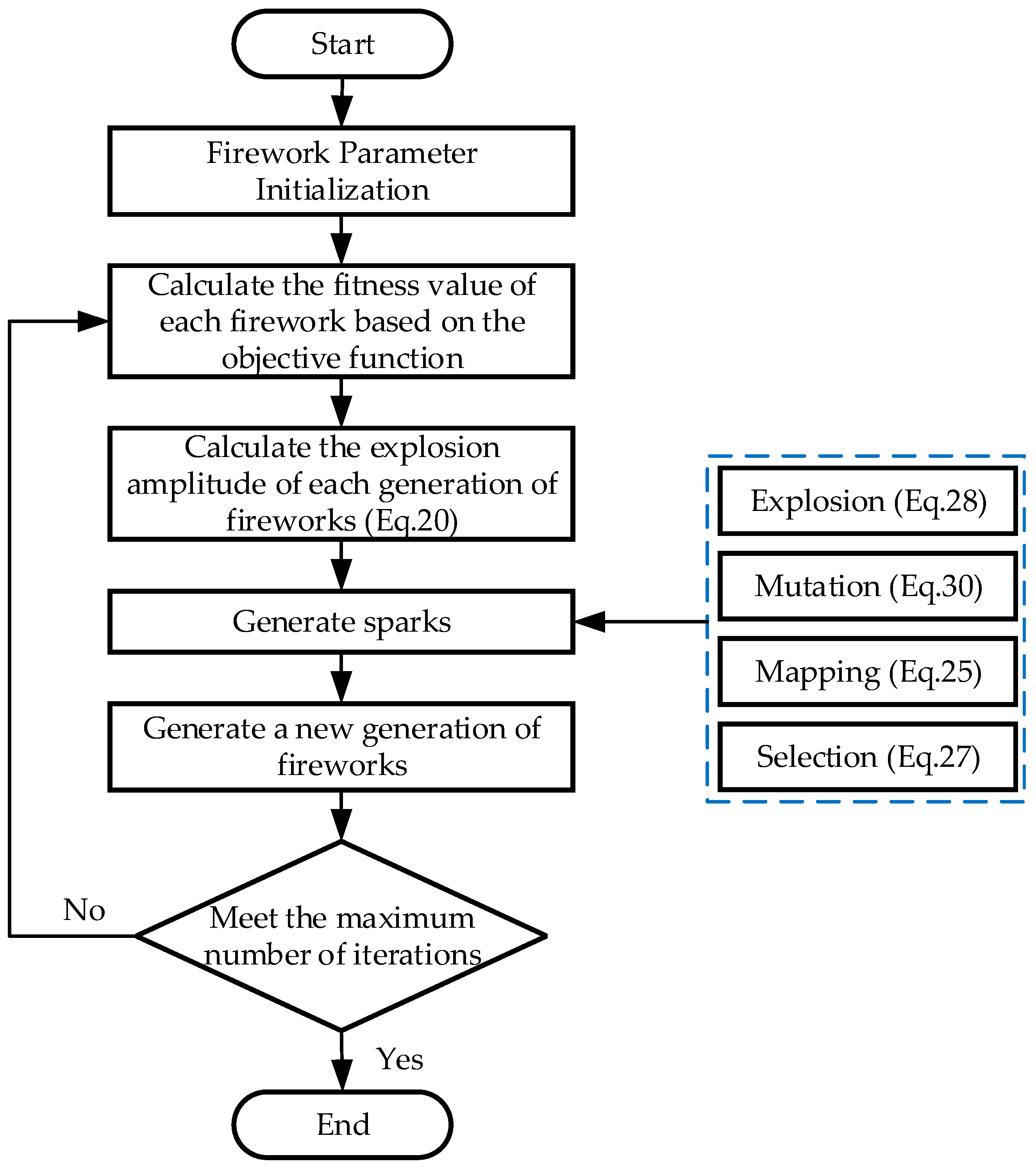
The operating mechanism of the MFWA procedure and overview parameter is depicted in Figure 3.
In this study, to improve the ride comfort of the seat suspension system, the mean squared error (MSE) of the human body vertical acceleration was defined as the objective function. To meet the desired control performance, this objective was evaluated and optimized using an evolutionary algorithm. The objective function is expressed as follows:
min J = 1 N k = 1 N a k 2
where N is the total number of sampling points and ak is the vertical acceleration of the human body at the k-th time step obtained from the simulation.
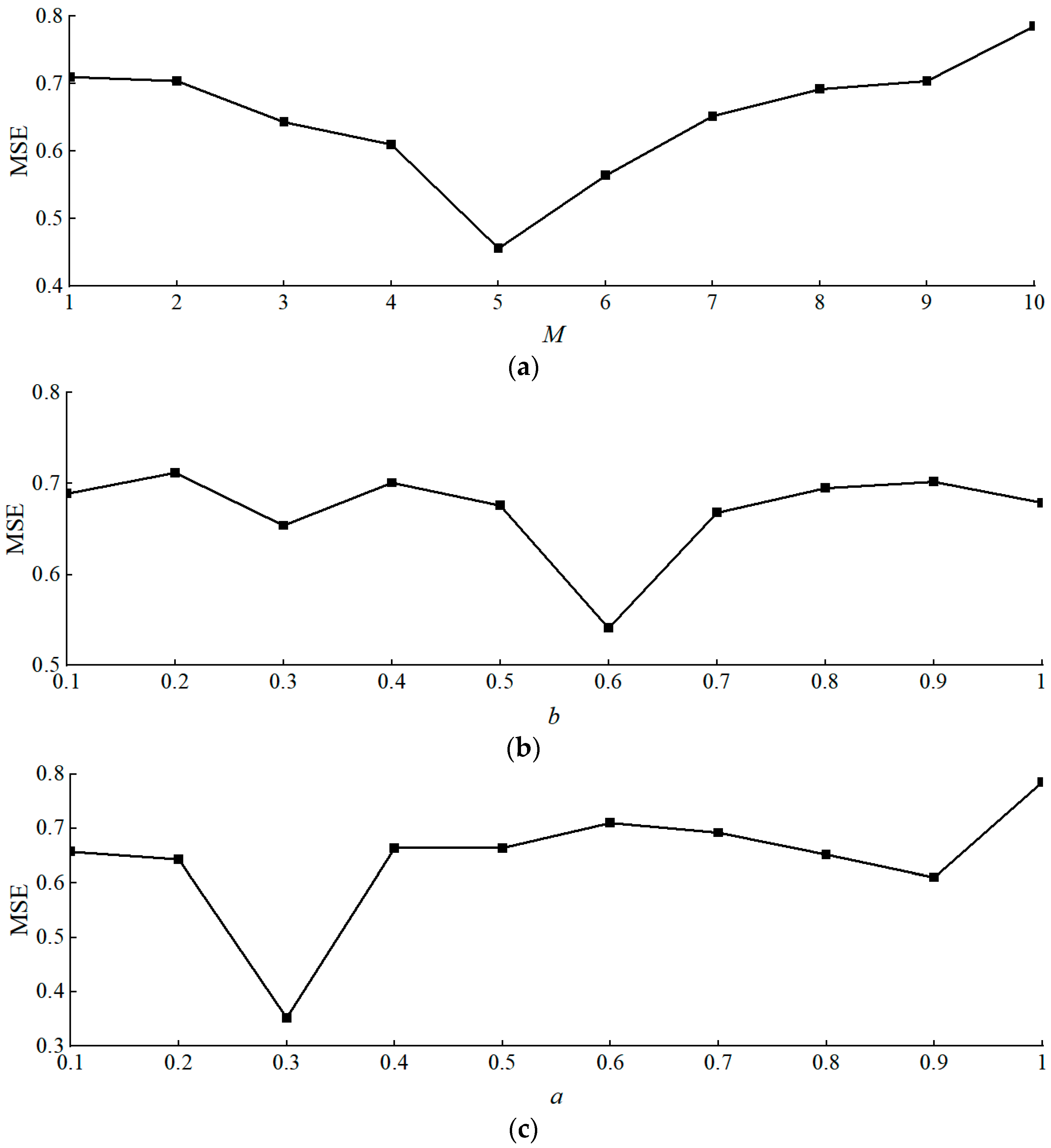
The algorithms’ parameters are set as follows: the population size N is 50, maximum iteration Tmax = 100, and dimension k = 3. The number of variation sparks is 5. Figure 4 presents the sensitivity analysis used to identify the optimal MFWA parameters M, a, and b based on the lowest MSE values. An overview of these parameters is provided in Table 3. The comparison between MFWA and in-house benchmark algorithms, such as Genetic Algorithm, Ant Colony Optimization, Particle Swarm Optimization, and Differential Evolution, is presented in Ref. [46]. MFWA demonstrates superior convergence speed and global search capability.

3.2. Fuzzy Logic Controller

A two-dimensional fuzzy logic controller (FLC) is employed, where the input variables of the FLC system are the human body acceleration z ¨ b and the relative velocity v rel = z ˙ seat z ˙ v of the seat suspension system, and the output variable is the required damping force Fc of the MRD. To restrict the variables within the range [−1, 1], the acceleration z ¨ b , relative velocity v rel , and output Fc are normalized as follows:
e c = 1 , 1 < z ¨ s / z ¨ s , max z ¨ s z ¨ s , max , 1 z ¨ s / z ¨ s , max 1 1 , z ¨ s / z ¨ s , max < 1
e = 1 , 1 < v rel / v rel , max v rel v rel , max , 1 v rel / v rel , max 1 1 , v rel / v rel , max < 1
u = 1 , 1 < F c / F c , max F c F c , max , 1 F c / F c , max 1 1 , F c / F c , max < 1
where z ¨ b , max , v rel , max and F c , max are the normalization factors.
For the normalized variables e, ec, and u, seven fuzzy subsets {NB NM NS ZE PS PM PB} are defined over their respective domains to represent the fuzzified states of the inputs and output. Gaussian membership functions are used for all input and output variables.
The design principle of the FLC fuzzy rules is as follows: when the human body acceleration and the relative velocity of the seat suspension move in the same direction, the MRD damping coefficient is set to its maximum, and the required damping force dissipates the greatest amount of energy from the suspension system; conversely, when the acceleration of the human–seat mass and the relative velocity of the seat suspension move in opposite directions, the MRD damping coefficient is minimized and the input current is set to zero, effectively rendering the suspension system equivalent to a passive system. The FLC rules are presented in Table 4.
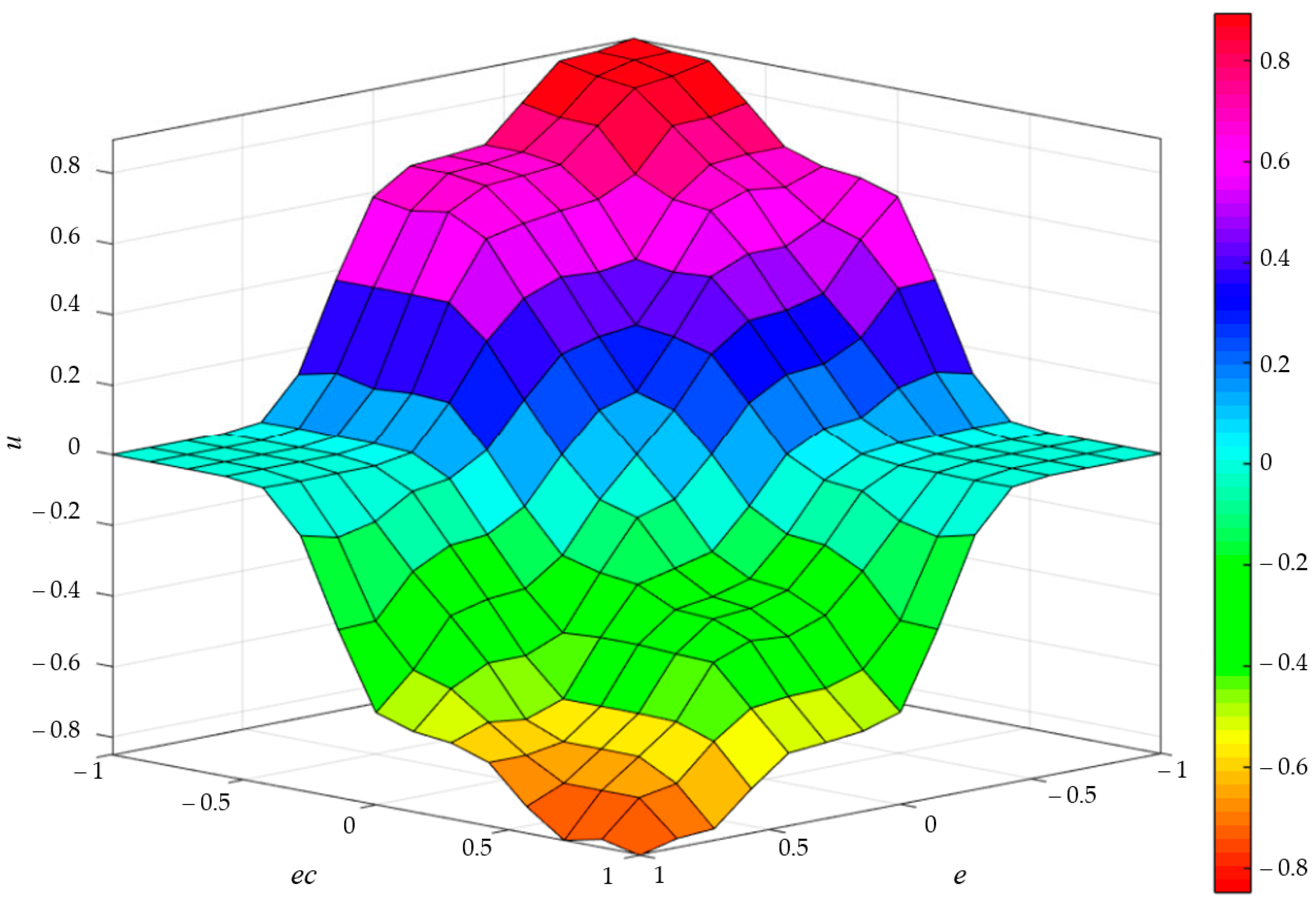
The established fuzzy control rules are processed using the Mamdani fuzzy inference method for logical reasoning and decision-making. The resulting control rule surface is shown in Figure 5. As illustrated, the T1 FLC rules exhibit a gradient distribution, indicating that the fuzzification mapping between the two-dimensional fuzzy system’s inputs and output performs effectively. The centroid method is employed to defuzzify the fuzzy output set, yielding precise values for the required damping force.

3.3. MFWA-FL CONTROL

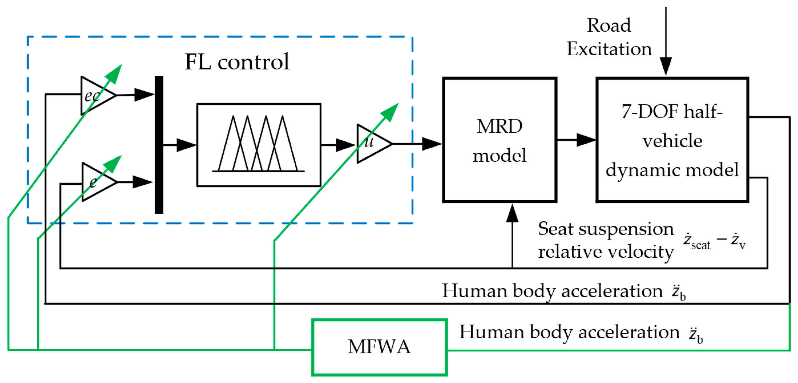
The MFWA-FL control is applied to the 7-DOF half-vehicle dynamic model integrated with a semi-active seat suspension system, as shown in Figure 6. When the vehicle encounters road disturbances, the fuzzy controller adjusts the MRD’s required damping force based on the relative velocity of the seat suspension and the human body acceleration obtained from the 7-DOF model. The MRD model then calculates the control voltage ϕ using Equation (18) and determines the actual damping force according to Equation (16), thereby controlling the MRD within the 7-DOF half-vehicle model and achieving vibration attenuation of the semi-active seat suspension system. MFWA optimizes the selection of the human acceleration gain ec, seat suspension relative velocity gain e, and demanded damping force gain coefficient u in the fuzzy controller throughout the entire fuzzy control process based on the principle of minimizing the root mean square error.

4. Simulation Results and Analysis

A 7-DOF dynamic model of a fuel cell commercial vehicle (FCCV) was developed in MATLAB/Simulink under random road excitation. Simulations were performed under both random and bump road conditions to analyze human vertical acceleration and dynamic deflection of seat suspension. Experimental tests under sinusoidal excitation were conducted to validate the simulation results and verify the practical effectiveness of the proposed MFWA-FL control strategy.
Simulations were performed using a fixed-step ode3 (Bogacki–Shampine) solver with a sampling time of 0.001 s. The control loop executed every 0.001 s, corresponding to the real-time controller cycle (1 kHz). The controller ran for 10 s under random road excitation and 15 s under bump excitation. The computations were executed on a system with an Intel Core i9-14900KF @ 3.20 GHz CPU(Intel Corporation, Santa Clara, CA, USA), 32 GB RAM(Lenovo Group Limited, Beijing, China), and an NVIDIA GeForce RTX 4060 (8 GB) GPU(NVIDIA Corporation, Santa Clara, CA, USA) running 64-bit Windows 10(Microsoft Corporation, Redmond, WA, USA).
To evaluate computational efficiency, the average execution time per control cycle was estimated using the MATLAB/Simulink Profiler. The PID controller required approximately 0.12 ms per cycle, while the MFWA-FL controller required about 0.37 ms per cycle due to the additional fuzzy inference and optimization computations. Both controllers operated well within the 1 ms sampling period, confirming the real-time feasibility of the proposed method.
In addition, the memory requirements of the MFWA optimization module were analyzed. The fuzzy rule base, optimization population, and control parameters occupied approximately 2.8 MB of memory during simulation, compared with 0.6 MB for the PID controller. This additional demand remains well within the capacity of common embedded control units (8–16 MB RAM), indicating that the MFWA-FL strategy is both computationally and memory efficient for real-time implementation.

4.1. Random Road Excitation

The time-domain expression of the random road excitation is given as
z ˙ r ( t ) = 2 π f 0 v z r ( t ) + 2 π n 0 G z r n 0 v w ( t )
where f0 = 0.01 Hz is the lower cut-off frequency, G z r n 0 is the road roughness coefficient of C-class road surface, v = 15 m/s is the vehicle speed, w ( t ) is standard Gaussian white noise with a zero mean and a unit power spectral density, and n0 = 0.1 m−1 is the reference spatial frequency. During the MATLAB/Simulink simulations, a consistent random road excitation signal was generated using a fixed noise sequence (seed = 23,341). This signal was applied to all evaluated control strategies, including passive, PID, and MFWA-FL control, enabling a fair and repeatable comparison of their performance.
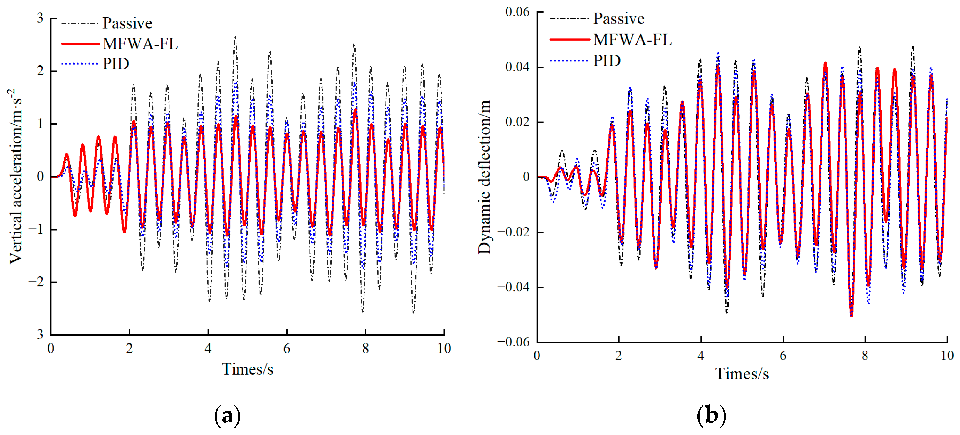
The time-domain responses of human vertical vibration and seat suspension dynamic deflection under C-class road excitation are shown in Figure 7. The RMS values and percentage improvements relative to the passive system are summarized in Table 5. As shown in the results, both PID and MFWA-FL controls improve vibration performance, while the MFWA-FL controller achieves a more significant reduction in vertical acceleration. Compared with the passive suspension, the MFWA-FL control reduces human vertical acceleration by 49.29%, representing a 27.98% improvement over PID control.
According to ISO 2631-1 vibration comfort standards [55], both the passive and PID-controlled systems are classified as “very uncomfortable” under C-class road conditions, whereas the MFWA-FL control achieves a “fairly uncomfortable” level, indicating improved comfort.
For seat suspension dynamic deflection, the proposed control strategy effectively reduces the peak value, achieving a 12.50% reduction compared with the passive system and 8.7% relative to PID control. This reduction decreases the likelihood of suspension bottoming and further enhances ride comfort. As shown in Figure 7a, the MFWA-FL control performs slightly worse than PID control during the first 2 s due to its higher computational complexity; however, it demonstrates superior adaptability and stability thereafter. Overall, the MFWA-FL controller significantly enhances ride comfort and stability for the 7-DOF vehicle model.
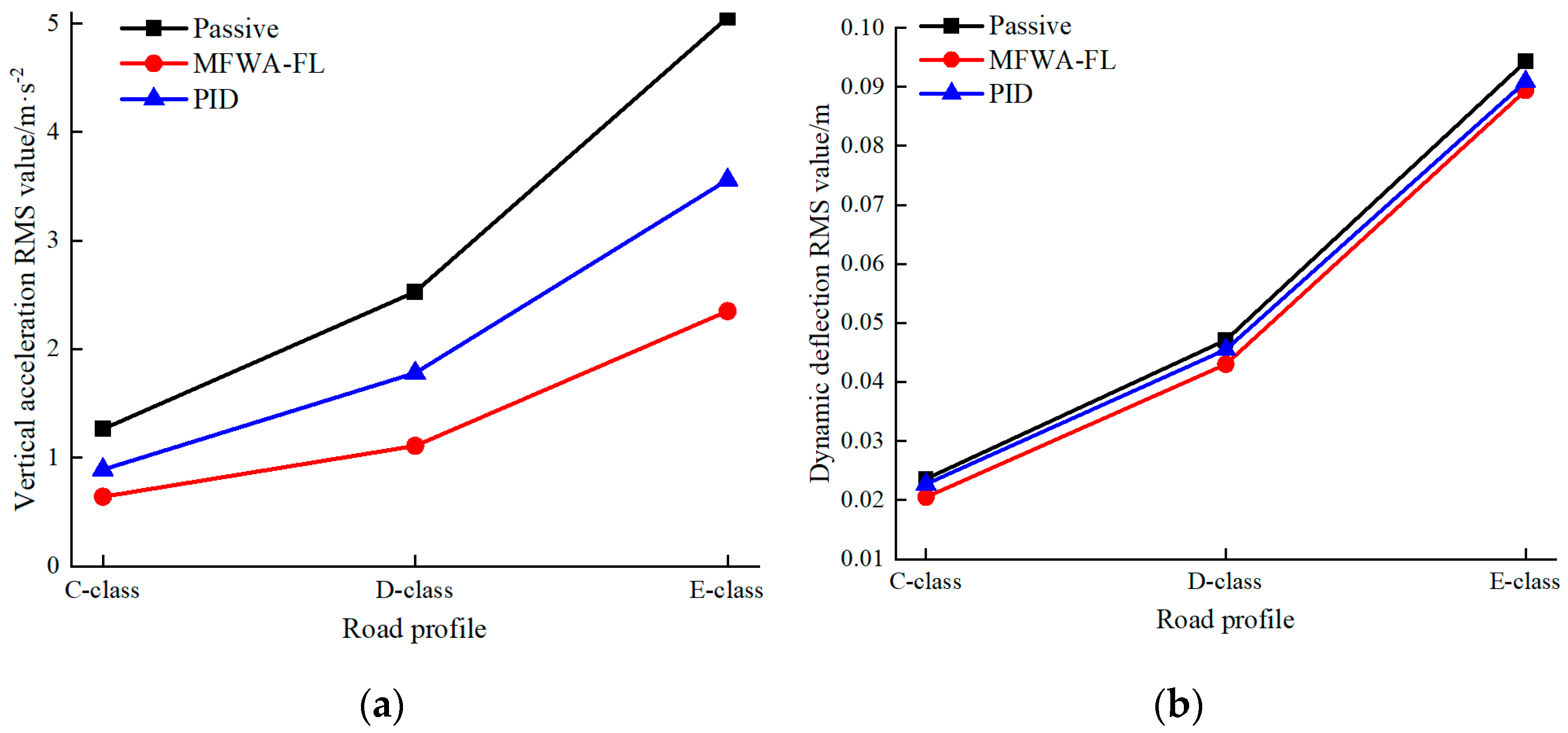
Figure 8 shows the RMS responses of human vertical acceleration and seat suspension dynamic deflection under C-, D-, and E-class random road excitations. As road roughness increases, both RMS values rise, indicating reduced ride comfort. The passive suspension system exhibits the largest increase, highlighting its poor adaptability to rougher road conditions. For human vertical acceleration, the MFWA-FL controller outperforms the PID controller, showing slower growth as road roughness worsens and thus providing better vibration suppression and improved comfort.
Regarding the RMS of seat suspension dynamic deflection, the MFWA-FL control slightly outperforms PID control and shows a clear improvement over the passive system. It effectively reduces deflection amplitude and minimizes the risk of suspension bottoming. Overall, as road irregularities intensify, the MFWA-FL controller maintains lower vibration and deflection levels, enhancing both ride comfort and system stability.
To evaluate the robustness of the proposed control strategy, a sensitivity analysis was performed by varying the human body mass across five levels (45 kg, 50 kg, 55 kg, 60 kg, and 65 kg), corresponding to 5/7 of the average human mass. The simulations were carried out on a C-class random road profile at a vehicle speed of 15 m/s. As illustrated in Figure 9, the MFWA-FL controller consistently achieves superior vibration suppression compared with the PID controller and the passive one across all body mass levels. With increasing body mass, the passive system shows slight improvement due to inertia effects; however, its performance still remains considerably inferior to that of the MFWA-FL and PID control strategies. These results confirm that the MFWA-FL controller maintains strong robustness to variations in human body mass, ensuring reliable vibration attenuation under diverse occupant conditions.

4.2. Bump Road Excitation

When an FCCV passes over speed bumps, potholes, or other road impacts, the road surface exerts a transient impact excitation on the vehicle system. The mathematical model of the bump road excitation is expressed as:
z r ( t ) = A 2 1 cos 2 π v L t , 0 t L v 0 , t > L v
where A = 0.05 m is the height of the bump, L = 0.8 m is the length of the bump, and the vehicle forward velocity as v = 5.6 m/s.
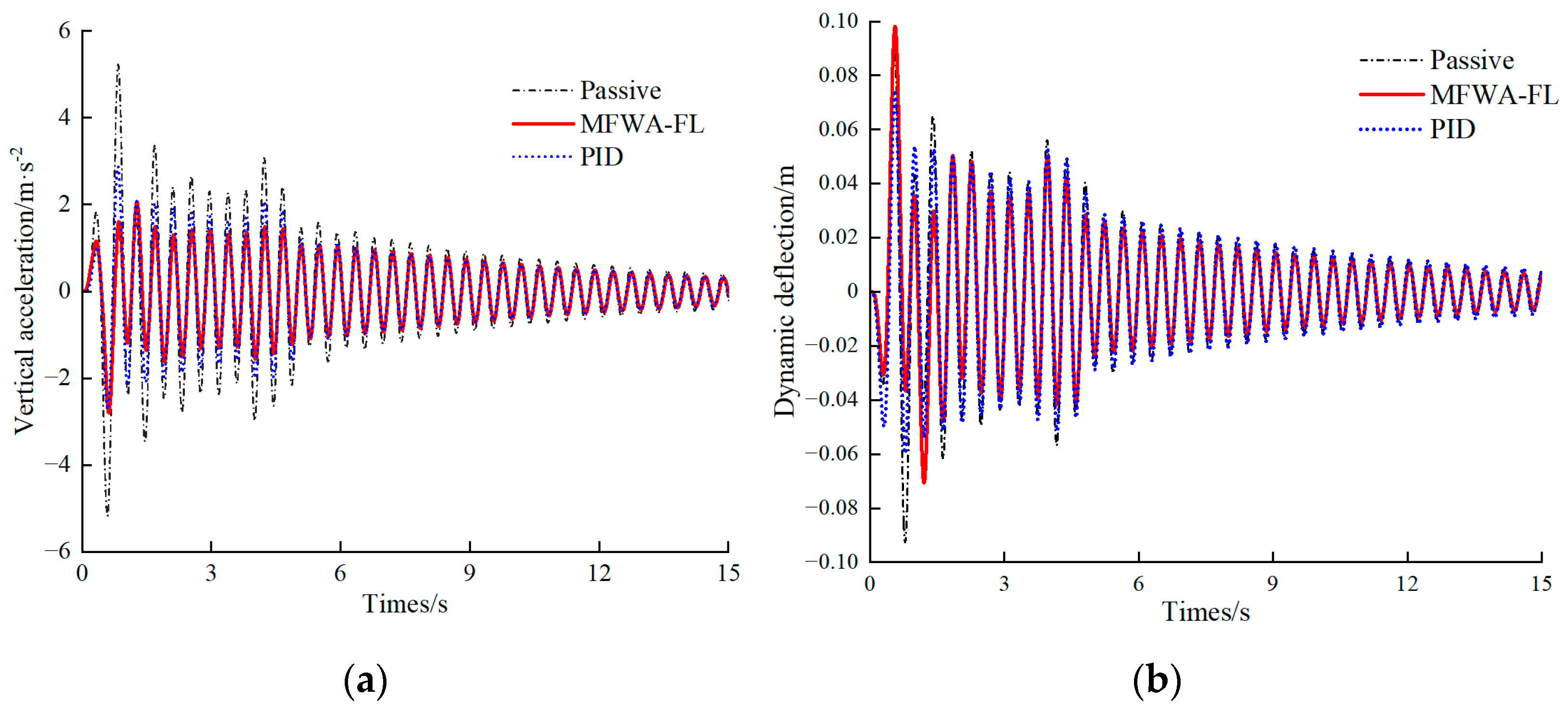
The time-domain responses and statistical characteristics of the 7-DOF half-vehicle model with the integrated semi-active seat suspension under bump road excitation are shown in Figure 10 and Table 6. As shown in Figure 10a, the MFWA-FL controller effectively suppressed human vertical vibration acceleration, achieving better attenuation performance compared with PID control.
As presented in Figure 10b, a short peak occurred around 1 s under MFWA-FL control, which slightly increased seat suspension deflection and the likelihood of bottoming. Nevertheless, the overall stability and convergence performance remained superior. According to Table 6, MFWA-FL control reduced the RMS value of human vertical acceleration by 43.03% compared with the passive system and by 16.48% relative to PID control. The RMS of seat suspension dynamic deflection was also reduced by 11.76% and 6.25% compared with the passive and PID systems, respectively. These results confirm that the MFWA-FL control effectively decreased vertical vibration acceleration, minimized the risk of suspension bottoming, and further improved ride comfort.

4.3. Experimental Validation

The proposed seat suspension and controller were experimentally validated using the setup shown in Figure 11. The seat was mounted on a vibration table (ES-50WLS3-445, Suzhou Dongling Vibration Test Instrument Co., Ltd., Suzhou, China) capable of generating controlled sinusoidal motion. Tri-axial acceleration sensors (1A314E, Jiangsu Donghua Testing Technology Co., Ltd., Taizhou, China) were attached to the upper and lower seat plates to measure vibration responses. The sensors have an axial sensitivity of 98 mV/g, a measurement range of ±50 g, a frequency range of 0.5–7000 Hz, and a resolution of 0.0005 g. All accelerometers were zero-calibrated before each trial to ensure accurate measurements.
The proposed controller was executed on a Links-RT real-time target machine, with a CPU model LINKS-C3U-SBC-01 (Intel T7500 dual-core processor, 2.2 GHz, 2 GB RAM, 300 GB hard disk; Intel Corporation, Santa Clara, CA, USA), running the VxWorks real-time operating system. Control signals from the Links-RT platform regulated the MRD current through its driver. A sinusoidal excitation with an amplitude of 0.025 m and frequency of 2 Hz was applied, with a human body mass of 75 kg. Each test condition was repeated three times to ensure repeatability and reliability. When the MRD current was set to 0 A, the system operated as a passive seat suspension. The effectiveness of the proposed control strategy was assessed by analyzing the vertical acceleration of the human body and the dynamic deflection of the seat suspension.
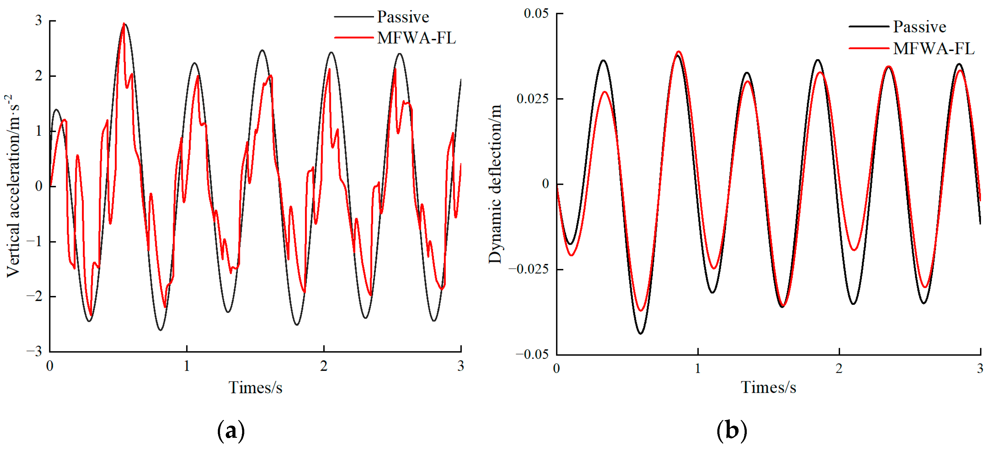
Figure 12 illustrates the time-domain responses of human vertical acceleration and seat suspension dynamic deflection under sinusoidal excitation. As shown in Figure 12a, the passive seat system exhibits asymmetric acceleration due to structural Coulomb friction damping. The proposed MFWA-FL controlled suspension reduces the peak-to-peak acceleration by approximately 14.08%. Figure 12b indicates a slight decrease in dynamic deflection, with more noticeable improvement during the damper rebound stroke.
Table 7 presents the RMS values of the experimental and simulated responses for vertical acceleration and dynamic deflection. Compared with the passive system, the MFWA-FL control reduces the experimental RMS vertical acceleration by 38.87% and the dynamic deflection by 9.52%, demonstrating improved ride comfort and vibration isolation. The simulated vertical acceleration under MFWA-FL control shows excellent agreement with the experimental data, yielding an RMS error of 2.23%, much lower than that of the passive system (6.78%). Similarly, the dynamic deflection exhibits good consistency between simulation and experiment, with an RMS error of 5.26% compared to 9.52% for the passive system. These results confirm that the proposed simulation model accurately represents the real dynamic behavior of the seat suspension system.
A control delay of approximately 0.015 s was observed, which primarily arises from sensor acquisition and filtering (~0.004 s), controller computation (~0.006 s), and MRD actuator response (~0.005 s). The control loop operated at a sampling frequency of 100 Hz, selected because the dominant vibration frequencies of the seat–suspension–driver system lie below 20 Hz. According to the Nyquist criterion, this frequency provides sufficient bandwidth to capture the relevant dynamics while ensuring real-time feasibility on the embedded controller. It should be noted that this validation was conducted in a hardware-in-the-loop (HIL) environment, where the observed delay is closely related to the controller’s processing speed. In real vehicle applications, additional latency may occur due to electromagnetic interference, mechanical hysteresis of the actuator, and signal transmission through the Electronic Control Unit (ECU). Nevertheless, such delays are typically of the same order of magnitude and have a limited effect on overall control performance when properly compensated.

5. Conclusions

In this study, a 7-DOF half-vehicle model of an FCCV was established, including the MRD-based seat suspension, tires, and chassis suspension. Human vertical acceleration and seat suspension dynamic deflection were used as evaluation metrics to assess the performance of the proposed MFWA-FL control strategy, which was compared with PID control and a passive suspension system. Simulation results show that under both random and bump road excitations, the MFWA-FL controller effectively reduces vertical acceleration and suspension deflection, outperforming PID and passive systems. Notably, the proposed control strategy mitigates vertical vibrations, improving ride comfort by over 40% compared with the passive system.
Experimental validation using a semi-active seat suspension test rig under sinusoidal excitation further confirmed the simulation results. The MFWA-FL controller effectively reduced human vertical acceleration and seat suspension deflection, demonstrating its practical effectiveness and potential for real-world application in FCCVs.
To fully validate the controller’s readiness for practical deployment, future work will pursue implementation in a full-scale vehicle. This will entail seamless integration with the vehicle ECU, extensive evaluation under real driving conditions, and a thorough investigation of the impacts of actuator dynamics, electromagnetic interference, and occupant variability. This transition beyond HIL and test rig environments is crucial for demonstrating the controller’s robustness and effectiveness in genuine FCCV applications.

Author Contributions

Conceptualization, X.C. and N.J.; methodology, N.J.; software, X.C.; validation, X.C.; investigation, N.J.; resources, X.C.; data curation, N.J.; writing—original draft preparation, X.C.; writing—review and editing, N.J.; visualization, N.J.; supervision, N.J.; project administration, N.J.; funding acquisition, N.J. All authors have read and agreed to the published version of the manuscript.

Funding

This research was funded by the Education Department of Henan Province, China, through the Henan Provincial Key Research Projects for Colleges and Universities (Grant Nos. 25A460022 and 25B460010), and by the Henan Institute of Technology, China, through the Henan Institute of Technology High-level Talent Startup Funding Project (Grant No. KQ2419).

Data Availability Statement

The data that support the fundings of this study are available from the corresponding author upon reasonable request.

Conflicts of Interest

The authors declare no conflicts of interest.

Abbreviations

The following abbreviations are used in this manuscript:
ABCArtificial Bee Colony
ACOAnt Colony Optimization
CSACuckoo Search
ECUElectronic Control Unit
FCCVsFuel cell commercial vehicles
FLFuzzy logic
FLCFuzzy logic controller
FWAFireworks Algorithm
GAsGenetic Algorithms
HILHardware in the loop
LQGLinear Quadratic Gaussian
MFWAModified Fireworks Algorithm
MRDMagnetorheological damper
MSEMean squared error
PIDProportional–Integral–Derivative
PSOParticle Swarm Optimization
7-DOFSeven-degree-of-freedom

Appendix A

Let A = A 11 A 12 A 21 A 22 , B = B 1 B 2 , and E = E 1 E 2 ; then
A 11 = 0 0 0 0 0 0 0 0 0 0 0 0 0 0 0 0 0 0 0 0 0 0 0 0 0 0 0 0 0 0 0 0 0 0 0 0 0 0 0 0 0 0 0 0 0 0 0 0 0 ,   A 12 = 1 0 0 0 0 0 0 0 1 0 0 0 0 0 0 0 1 0 0 0 0 0 0 0 1 0 0 0 0 0 0 0 1 0 0 0 0 0 0 0 1 0 0 0 0 0 0 0 1 ,
A 21 = k tf + k sf m tf 0 0 k sf m tf k sf l f m tf 0 0 0 k tr 1 + k tr 2 + k sr m tr 1 + m tr 2 k tr 1 l r 1 k tr 2 l r 2 m tr 1 + m tr 2 k sr m tr 1 + m tr 2 k sr l r m tr 1 + m tr 2 0 0 0 k tr 1 l r 1 k tr 2 l r 2 I tr k tr 1 l r 1 2 + k tr 2 l r 2 2 I tr 0 0 0 0 k sf m s k sr m s 0 k sf + k sr + k seat m s k sf l f k sr l r + k seat l b m s k seat m s 0 k sf l f I s k sr l r I s 0 k sf l f k sr l r + k seat l b I s k sf l f 2 + k sr l r 2 + k seat l b 2 I s k seat l b I s 0 0 0 0 k seat m seat k seat l b m seat k seat + k c m seat k c m seat 0 0 0 0 0 k c m b k c m b ,
A 22 = c tf + c sf m tf 0 0 c sf m tf c sf l f m tf 0 0 0 c tr 1 + c tr 2 + c sr m tr 1 + m tr 2 c tr 1 l r 1 c tr 2 l r 2 m tr 1 + m tr 2 c sr m tr 1 + m tr 2 c sr l r m tr 1 + m tr 2 0 0 0 c tr 1 l r 1 c tr 2 l r 2 I tr c tr 1 l r 1 2 + c tr 2 l r 2 2 I tr 0 0 0 0 c sf m s c sr m s 0 c sf + c sr m s c sf l f c sr l r m s 0 0 c sf l f I s c sr l r I s 0 c sf l f c sr l r I s c sf l f 2 + c sr l r 2 I s 0 0 0 0 0 0 0 c c m seat c c m seat 0 0 0 0 0 c c m b c c m b ,
E 1 = 0 0 0 0 0 0 0 0 0 0 0 0 0 0 0 0 0 0 0 0 0 0 0 0 0 0 0 0 0 0 0 0 0 0 0 0 0 0 0 0 0 0 ,   E 2 = k tf m tf 0 0 c tf m tf 0 0 0 k tr 1 m tr 1 + m tr 2 k tr 2 m tr 1 + m tr 2 0 c tr 1 m tr 1 + m tr 2 c tr 2 m tr 1 + m tr 2 0 k tr 1 l r 1 I tr k tr 2 l r 2 I tr 0 c tr 1 l r 1 I tr c tr 2 l r 2 I tr 0 0 0 0 0 0 0 0 0 0 0 0 0 0 0 0 0 0 0 0 0 0 0 0 ,
C = 0 0 0 1 l b 0 1 0 0 0 0 0 0 0 0 0 0 1 l b 1 0 0 0 0 0 0 0 0 0 0 0 0 0 0 1 0 0 0 0 0 0 0 0 0 0 0 0 k c m b k c m b 0 0 0 0 0 c c m b c c m b .

References

  1. Albatayneh, A.; Juaidi, A.; Jaradat, M.; Manzano-Agugliaro, F. Future of electric and hydrogen cars and trucks: An overview. Energies 2023, 16, 3230. [Google Scholar] [CrossRef]
  2. Jokela, T.; Kim, B.; Gao, B.; Wellers, M.; Peng, Z. A review of fuel cell technology for commercial vehicle applications. Int. J. Heavy Veh. Syst. 2021, 28, 650–678. [Google Scholar] [CrossRef]
  3. Kast, J.; Vijayagopal, R.; Gangloff, J.J.; Marcinkoski, J. Clean commercial transportation: Medium and heavy duty fuel cell electric trucks. Int. J. Hydrog. Energy 2017, 42, 4508–4517. [Google Scholar] [CrossRef]
  4. Togun, H.; Basem, A.; Abdulrazzaq, T.; Biswas, N.; Abed, A.M.; dhabab, J.M.; Chattopadhyay, A.; Slimi, K.; Paul, D.; Barmavatu, P.; et al. Development and comparative analysis between battery electric vehicles (BEV) and fuel cell electric vehicles (FCEV). Appl. Energy 2025, 388, 125726–125741. [Google Scholar] [CrossRef]
  5. Douadi, O.; Ravi, R.; Faqir, M.; Balasubramanian, D.; Kale, U.; Kilikevičius, A. A study on zero-emission vehicle technologies: Comparing hydrogen fuel cell and battery electric solutions for decarbonization of transportation. Therm. Sci. Eng. Prog. 2025, 66, 103990–104015. [Google Scholar] [CrossRef]
  6. Hebala, A.; Abdelkader, M.I.; Ibrahim, R.A. Comparative analysis of energy consumption and performance metrics in fuel cell, battery, and hybrid electric vehicles under varying wind and road conditions. Technologies 2025, 13, 150. [Google Scholar] [CrossRef]
  7. Li, Y.; Dai, L.; Guo, Z.; Chi, M. Carbody abnormal lateral vibration failure of high–speed train induced by the coupling factor of the wheel re–profiling method and excessive rail wear. Eng. Fail. Anal. 2024, 160, 108170–108186. [Google Scholar] [CrossRef]
  8. Metered, H.; Ibrahim, I.M. Vibration mitigation of commercial vehicle active tandem axle suspension system. SAE Int. J. Commer. Veh. 2022, 15, 275–288. [Google Scholar] [CrossRef]
  9. Sureshkumar, G.; Kumaraswamidhas, L.A.; Pham, D. Optimization of structural parameters through objective-evaluation of ride comfort in a heavy-duty commercial vehicle. Cogent Eng. 2020, 7, 1743408. [Google Scholar] [CrossRef]
  10. Lv, X.; Ji, Y.; Zhao, H.; Zhang, J.; Zhang, G.; Zhang, L. Research review of a vehicle energy-regenerative suspension system. Energies 2020, 13, 441. [Google Scholar] [CrossRef]
  11. Long, G.; Ding, F.; Zhang, N.; Zhang, J.; Qin, A. Regenerative active suspension system with residual energy for in-wheel motor driven electric vehicle. Appl. Energy 2020, 260, 114180–114197. [Google Scholar] [CrossRef]
  12. Atindana, V.A.; Xu, X.; Kwaku, N.J.; Akayeti, A.; Jiang, X. A novel semi-active control of an integrated chassis and seat quasi-zero stiffness suspension system for off-road vehicles. J. Vib. Control 2024, 30, 5536–5559. [Google Scholar] [CrossRef]
  13. Qiu, C.; Liu, X.; Shen, Y. Improvement of the vehicle seat suspension system incorporating the mechatronic inerter element. World Electr. Veh. J. 2023, 14, 29. [Google Scholar] [CrossRef]
  14. Zha, J.; Nguyen, V.; Su, B.; Jiao, R.; Ni, D. Performance of the seat suspension system using negative stiffness structure on improving the driver’s ride comfort. SAE Int. J. Veh. Dyn. Stab. NVH 2022, 6, 135–146. [Google Scholar] [CrossRef]
  15. Chen, X.; Wang, Z.; Shi, H.; Jiang, N.; Zhao, S.; Qiu, Y.; Liu, Q. Review of agricultural machinery seat semi-active suspension systems for ride comfort. Machines 2025, 13, 246. [Google Scholar] [CrossRef]
  16. Li, P.; Dong, X.; Ran, J.; Fei, Z.; Wu, L.; Xu, D. Performance evaluation of a novel semi-active absorption and isolation co-control strategy with magnetorheological seat suspension for commercial vehicle. Smart Mater. Struct. 2024, 33, 105016–105029. [Google Scholar] [CrossRef]
  17. Yan, S.; Sun, W.; Gao, H. Vibration suppression for motor-driven uncertain active suspensions with hard constraints and analysis of energy consumption. IEEE Trans. Syst. Man Cybern. Syst. 2022, 52, 618–630. [Google Scholar] [CrossRef]
  18. Maciejewski, I.; Pecolt, S.; Blazejewski, A.; Jereczek, B.; Glowinski, S.; Krzyzynski, T. Energy harvesting effectiveness of an active horizontal seat suspension under random vibration of varying intensity. Mech. Syst. Signal Process. 2025, 237, 113000–113021. [Google Scholar] [CrossRef]
  19. Čerškus, A.; Šešok, N.; Bučinskas, V. Implementation of lookup tables for different optimization strategies of semi-active car suspension system. J. Vibroeng. 2025, 27, 497–524. [Google Scholar] [CrossRef]
  20. Feng, H.; Zhou, Y.; Li, S.; Cheng, G.; Ma, S.; Li, Y. Adaptive backstepping control with time-delay compensation for MR-damper-based vehicle seat suspension. Actuators 2025, 14, 178. [Google Scholar] [CrossRef]
  21. Shi, X.; Li, H.; Fu, K. Design of a direct current controller for magnetorheological semi-active suspensions with nonlinear constraints. Proc. Inst. Mech. Eng. Part D J. Automob. Eng. 2024, 239, 3266–3277. [Google Scholar] [CrossRef]
  22. Ahn, D.V.; Kim, K.; Oh, J.; Seo, J.; Lee, J.W.; Park, Y.J. Optimal control of semi-active suspension for agricultural tractors using linear quadratic gaussian control. Sensors 2023, 23, 6474. [Google Scholar] [CrossRef]
  23. Ding, R.; Wang, P.; Li, A.; Wang, R.; Sun, D.; Xu, K. H control and experimental study of MR semi-active suspension with actuator response delay. Metrol. Meas. Syst. 2024, 31, 797–812. [Google Scholar] [CrossRef]
  24. Samaroo, K.; Awan, A.W.; Islam, S. Semi-active suspension design for an in-wheel-motor-driven electric vehicle using a dynamic vibration-absorbing structure and PID-controlled magnetorheological damper. Machines 2025, 13, 47. [Google Scholar] [CrossRef]
  25. Zhang, K.; As’arry, A.; Zhu, L.; Hairuddin, A.A.; Hassan, M.K.; Md Zain, M.Z. Enhancing ride comfort of semi-active suspension through collaboration control using dung beetle optimizer optimized Fuzzy PID controller. Adv. Mech. Eng. 2025, 17, 1–14. [Google Scholar] [CrossRef]
  26. Sun, Y.; Qiang, H.; Wang, L.; Ji, W.; Mardani, A. A fuzzy-logic-system-based cooperative control for the multielectromagnets suspension system of maglev trains with experimental verification. IEEE Trans. Fuzzy Syst. 2023, 31, 3411–3422. [Google Scholar] [CrossRef]
  27. Fang, Y.; Bai, R. Adaptive fuzzy sensor failure compensation for active suspension systems with multiple sensor failures. Syst. Sci. Control Eng. 2021, 10, 229–240. [Google Scholar] [CrossRef]
  28. Hsiao, C.-Y.; Wang, Y.-H. Evaluation of ride comfort for active suspension system based on self-tuning fuzzy sliding mode control. Int. J. Control Autom. Syst. 2022, 20, 1131–1141. [Google Scholar] [CrossRef]
  29. Chen, L.; Wang, Q.; Hu, C. Adaptive fuzzy command filtered backstepping control for uncertain pure-feedback systems. ISA Trans. 2022, 129, 204–213. [Google Scholar] [CrossRef]
  30. Soudani, M.S.; Aouiche, A.; Ghanai, M.; Chafaa, K. Advanced active suspension control: A three-input fuzzy logic approach with jerk feedback for enhanced performance and robustness. Measurement 2024, 229, 114326–114347. [Google Scholar] [CrossRef]
  31. Zhang, X.; Chen, D.; Mi, J. Fuzzy decision rule-based online classification algorithm in fuzzy formal decision contexts. IEEE Trans. Fuzzy Syst. 2023, 31, 3263–3277. [Google Scholar] [CrossRef]
  32. Tayyebi, S. An adaptive fuzzy sliding mode control under model uncertainties and disturbances: Second-order non-linear system. J. Braz. Soc. Mech. Sci. 2021, 43, 533–543. [Google Scholar] [CrossRef]
  33. Brás, G.; Silva, A.M.; Wanner, E.F. A genetic algorithm for rule extraction in fuzzy adaptive learning control networks. Genet. Program. Evolvable Mach. 2024, 25, 1–14. [Google Scholar] [CrossRef]
  34. Singh, N.; Sharma, A.K.; Tiwari, M.; Jasiński, M.; Leonowicz, Z.; Rusek, S.; Gono, R. Robust control of SEDCM by fuzzy-PSO. Electronics 2023, 12, 355. [Google Scholar] [CrossRef]
  35. Mao, J. Optimizing enterprise marketing project portfolios using fuzzy ant colony optimization. Int. J. Comput. Commun. Control 2024, 19, 1–14. [Google Scholar] [CrossRef]
  36. Nitish; Singh, A.K. Design of enhanced active suspension system with metaheuristic-based LQG control and ANFIS-based actuation. Mech. Based Des. Struct. Mach. 2025, 53, 6196–6227. [Google Scholar] [CrossRef]
  37. Florea, A.; Cofaru, I.; Patrausanu, A.; Cofaru, N.; Fiore, U. Superposition of populations in multi-objective evolutionary optimization of car suspensions. Eng. Appl. Artif. Intel. 2023, 126, 107026–107040. [Google Scholar] [CrossRef]
  38. Ma, K.; Zhang, Y.; Ren, C.; Chen, Y.; Zhou, P.; Chen, Y. Effect of time-delay feedback control on vehicle seat vibration reduction and suspension performance. J. Low Freq. Noise Vib. Act. Control 2022, 41, 1214–1233. [Google Scholar] [CrossRef]
  39. Abdul Zahra, A.K.; Abdalla, T.Y. Design of fuzzy super twisting sliding mode control scheme for unknown full vehicle active suspension systems using an artificial bee colony optimization algorithm. Asian J. Control 2020, 23, 1966–1981. [Google Scholar] [CrossRef]
  40. He, S.; Chen, K.; Xu, E.; Wang, W.; Jiang, Z.; Chiementin, X. Commercial vehicle ride comfort optimization based on intelligent algorithms and nonlinear damping. Shock Vib. 2019, 2019, 2973190. [Google Scholar] [CrossRef]
  41. Chen, Y.; Li, L.; Zhao, X.; Xiao, J.; Wu, Q.; Tan, Y. Simplified hybrid fireworks algorithm. Knowl.-Based Syst. 2019, 173, 128–139. [Google Scholar] [CrossRef]
  42. Wei, W.; Ouyang, H.; Zhang, C.; Li, S.; Fu, L.; Gao, L. Dynamic collaborative fireworks algorithm and its applications in robust pole assignment optimization. Appl Soft Comput 2021, 100, 106999–110717. [Google Scholar] [CrossRef]
  43. Lei, K.; Wu, Y. Dynamic multi-swarm competitive fireworks algorithm for global optimization and engineering constraint problems. Int. J. Uncertain. Fuzziness Knowl.-Based Syst. 2023, 31, 619–648. [Google Scholar] [CrossRef]
  44. Aleardi, M.; Pierini, S.; Sajeva, A. Assessing the performances of recent global search algorithms using analytic objective functions and seismic optimization problems. Geophysics 2019, 84, R767–R781. [Google Scholar] [CrossRef]
  45. Gholizadeh, S.; Milany, A. An improved fireworks algorithm for discrete sizing optimization of steel skeletal structures. Eng. Optim. 2018, 50, 1829–1849. [Google Scholar] [CrossRef]
  46. Wei, W.; Ouyang, H.; Li, S.; Zhao, X.; Zou, D. A modified fireworks algorithm with dynamic search interval based on closed-loop control. Math. Comput. Simul. 2022, 200, 329–360. [Google Scholar] [CrossRef]
  47. Yadav, A.M.; Tripathi, K.N.; Sharma, S.C. An enhanced multi-objective fireworks algorithm for task scheduling in fog computing environment. Clust. Comput. 2021, 25, 983–998. [Google Scholar] [CrossRef]
  48. Yang, C.; Liu, K.; Jiao, X.; Wang, W.; Chen, R.; You, S. An adaptive firework algorithm optimization-based intelligent energy management strategy for plug-in hybrid electric vehicles. Energy 2022, 239, 122120–122135. [Google Scholar] [CrossRef]
  49. Zhang, Y.; Luo, T.; Guo, J.; Li, X. Study on the dual-segment arctangent model of magnetorheological damper (MRD). Smart Mater. Struct. 2024, 34, 15024–015038. [Google Scholar] [CrossRef]
  50. Steven Diaz-Choque, C.; Felix-Herran, L.C.; Galluzzi, R.; Cespi, R.; Lozoya-Santos, J.D.J.; Ramirez-Mendoza, R.A. Adaptive control strategy for automotive magnetorheological dampers based on artificial neural networks. IEEE Access 2025, 13, 60455–60469. [Google Scholar] [CrossRef]
  51. Jin, Z.; Yang, F.; Rui, X.; Jiang, M.; Wang, J. Design, modeling, and vibration control of a damper based on magnetorheological fluid and elastomer. Actuators 2024, 13, 241. [Google Scholar] [CrossRef]
  52. El Majdoub, K.; Ghani, D.; Giri, F.; Chaoui, F.Z. Adaptive semi-active suspension of quarter-vehicle with magnetorheological damper. J. Dyn. Syst. Meas. Control 2015, 137, 021010. [Google Scholar] [CrossRef]
  53. Phu, D.X.; An, J.-H.; Choi, S.-B. A novel adaptive PID controller with application to vibration control of a semi-active vehicle seat suspension. Appl. Sci. 2017, 7, 1055. [Google Scholar] [CrossRef]
  54. Meng, X.; Tan, Y. Multi-guiding spark fireworks algorithm: Solving multimodal functions by multiple guiding sparks in fireworks algorithm. Swarm Evol. Comput. 2024, 85, 101458. [Google Scholar] [CrossRef]
  55. ISO 2631-1:1997; Mechanical vibration and shock — Evaluation of human exposure to whole-body vibration — Part 1: General requirements. International Organization for Standardization: Geneva, Switzerland, 1997.
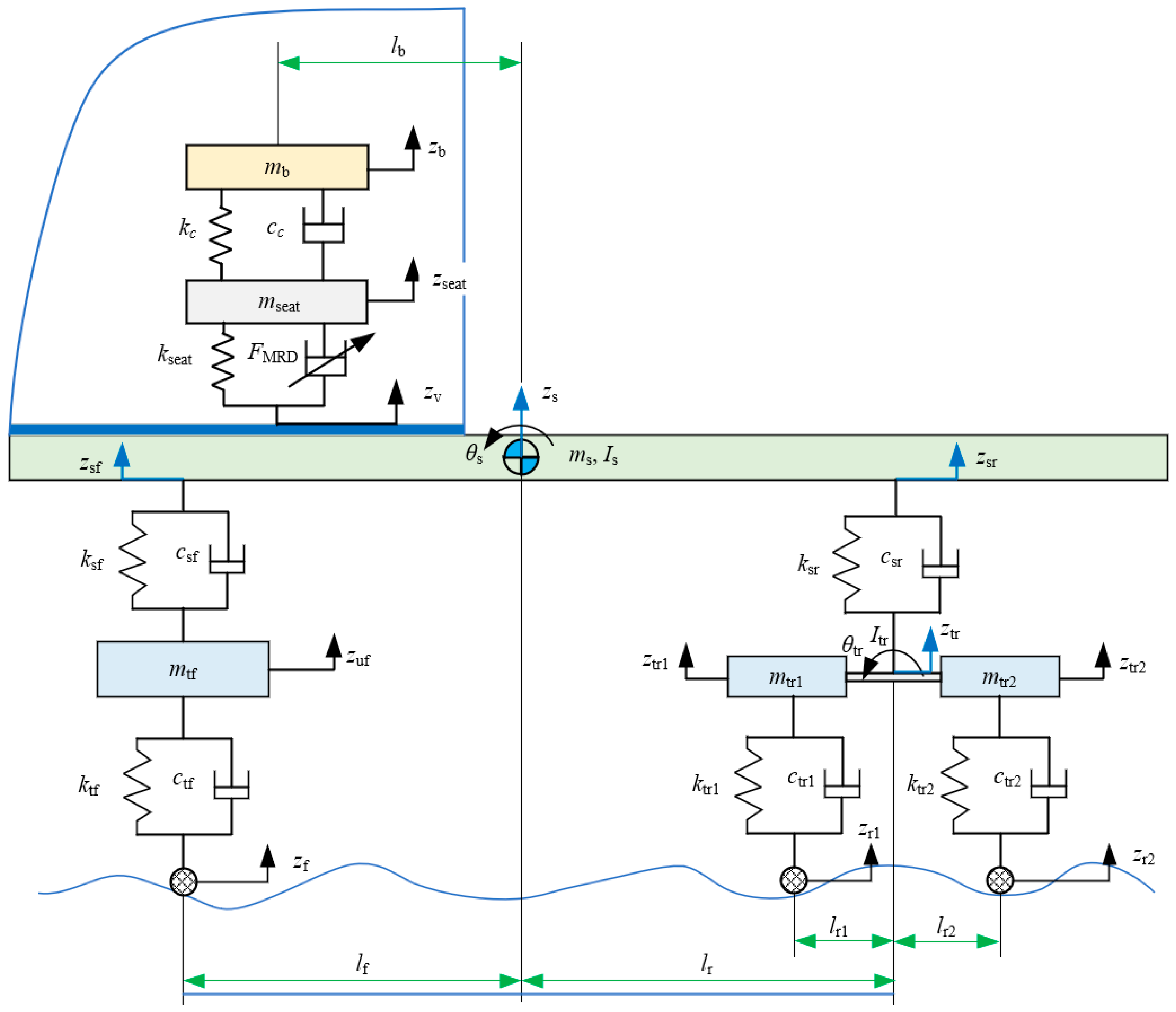
Figure 1. 7-DOF half-car model.
Wevj 16 00585 g001
Figure 2. Bouc–Wen model for MRD.
Wevj 16 00585 g002
Figure 3. The operating mechanism of MFWA procedure.
Wevj 16 00585 g003
Figure 4. Sensitivity analysis for MFWA parameters: (a) spark number M; (b) hiven constant b; and (c) given constant a.
Wevj 16 00585 g004
Figure 5. Fuzzy control surface of the T1FLC system.
Wevj 16 00585 g005
Figure 6. Schematic diagram of the MFWA-FL control system.
Wevj 16 00585 g006
Figure 7. Time-domain response under C-class road excitation: (a) vertical acceleration of human body; (b) dynamic deflection of seat suspension.
Wevj 16 00585 g007
Figure 8. Time-domain response under different classes of random road excitation: (a) vertical acceleration RMS value of human body; (b) dynamic deflection RMS value of seat suspension.
Wevj 16 00585 g008
Figure 9. Time-domain responses of the seat suspension system under C-class random road excitation with varying human body masses: (a) vertical acceleration RMS value of human body; (b) dynamic deflection RMS value of seat suspension.
Wevj 16 00585 g009
Figure 10. Time-domain response under bump road excitation: (a) vertical acceleration of human body; (b) dynamic deflection of seat suspension.
Wevj 16 00585 g010
Figure 11. Semi-active seat suspension test rig.
Wevj 16 00585 g011
Figure 12. Experimentally validated simulation results: (a) Vertical acceleration of human body; (b) Dynamic deflection of seat suspension.
Wevj 16 00585 g012
Table 1. Parameters of the 7-DOF vehicle system.
ParametersValueDescription
mtf565 kgFront axle mass
mtr1495 kgMiddle axle mass
mtr2495 kgRear axle mass
ms7800 kgVehicle body mass
mseat28 kgSeat mass
mb55 kg5/7 human body mass
Is5885 kg·m2Vehicle body moment of inertia
Itr35 kg·m2Equalizer suspension moment of inertia
ktf1,000,000 N·m−1Front axle tire stiffness
ktr11,000,000 N·m−1Middle axle tire stiffness
ktr21,000,000 N·m−1Rear axle tire stiffness
ksf7,345,000 N·m−1Front suspension spring stiffness
ksr20,560,000 N·m−1Rear suspension spring stiffness
kseat4600 N·m−1Seat suspension spring stiffness
kc90,000 N·m−1Seat cushion stiffness
ctf1000 N·s·m−1Front axle tire damping
ctr11000 N·s·m−1Middle axle tire damping
ctr21000 N·s·m−1Rear axle tire damping
csf4564 N·s·m−1Front suspension damper damping
csr66,885 N·s·m−1Rear suspension damper damping
cc2500 N·s·m−1Seat cushion damping
lf2.318 mDistance from front axle to vehicle body center of gravity
lr3.782 mDistance from equalizer suspension center to vehicle body center of gravity
lr10.86 mDistance from middle axle to equalizer suspension center
lr20.86 mDistance from rear axle to equalizer suspension center
lb1.335 mDistance from seat center to vehicle body center of gravity
Table 2. Parameter numerical values of the Bouc–Wen model [53].
ParametersValueDescription
k00 N·m−1Linear spring stiffness
C0a990 N·s·m−1Viscous damping coefficient
C0b3095 N·s·m−1·V−1 Viscous damping coefficient influenced by ϕ
αa545 N·m−1Stiffness of ω
αb620 N·m−1Stiffness of ω influenced by v
λ4Positive parameter of hysteresis loop
ρ48Positive parameter of hysteresis loop
β48Positive parameter of hysteresis loop
Table 3. MFWA parameters.
Parameter NameValueParameter NameValue
Population, N50Spark number, M5
Iteration, Tmax100Given constant, a0.3
Dimension, k3Given constant, b0.6
Variation spark number, B5
Table 4. Fuzzy control rules of FLC.
uec
NBNMNSZEPSPMPB
eNBPBPBPMPMZEZEZE
NMPBPBPMPSZEZEZE
NSPMPMPSPSZEZEZE
ZEPMPMPSZENSNSNM
PSZEZEZENSNSNSNM
PMZEZEZENSNMNMNB
PBZEZEZENMNMNBNB
Table 5. RMS values and percentage improvement for parameter of interest under C-class road excitation.
IndexPassiveMFWA-FLPID
Vertical acceleration (m/s2)1.264 (benchmark)0.641 (49.29%)0.890 (29.59%)
Dynamic deflection (m)0.024 (benchmark)0.021 (12.50%)0.023 (4.17%)
Table 6. RMS values and percentage improvement for parameter of interest under bump road excitation.
IndexPassiveMFWA-FLPID
Vertical acceleration (m/s2)0.925(benchmark)0.527(43.03%)0.631(31.78%)
Dynamic deflection (m)0.017(benchmark)0.015(11.76%)0.016(5.88%)
Table 7. RMS values of experiment and simulation.
IndexVertical acceleration (m/s2)Dynamic Deflection (m)
PassiveMFWA-FLPassiveMFWA-FL
Experiment1.6811.0780.0210.019
simulation1.7951.0540.0230.018
Disclaimer/Publisher’s Note: The statements, opinions and data contained in all publications are solely those of the individual author(s) and contributor(s) and not of MDPI and/or the editor(s). MDPI and/or the editor(s) disclaim responsibility for any injury to people or property resulting from any ideas, methods, instructions or products referred to in the content.