Abstract
To resolve the inherent coupling conflict between trajectory tracking and lateral stability in distributed electric drive buses, this paper proposes a hierarchical cooperative control framework. A simplified two-degree-of-freedom (2-DOF) vehicle model is first established, and kinematically derived reference states for stable motion are computed. At the upper level, a model predictive controller (MPC) generates real-time steering commands while explicitly minimizing lateral tracking error. At the lower level, a proportional integral derivative (PID)-based roll moment controller and a linear quadratic regulator (LQR)-based direct yaw moment controller are designed, with four-wheel torque distribution achieved via quadratic programming subject to friction circle and vertical load constraints. Co-simulation results using TruckSim and MATLAB/Simulink demonstrate that, during high-speed single-lane-change maneuvers, peak lateral error is reduced by 11.59–18.09%, and root-mean-square (RMS) error by 8.67–14.77%. Under medium-speed double-lane-change conditions, corresponding reductions of 3.85–12.16% and 4.48–11.33% are achieved, respectively. These results fully validate the effectiveness of the proposed strategy. Compared with the existing MPC–direct yaw moment control (DYC) decoupled control framework, the coordinated control strategy proposed in this paper achieves the optimal trade-off between trajectory tracking and lateral stability while maintaining the quadratic programming solution delay below 0.5 milliseconds.
1. Introduction
Driven by the accelerating electrification, intelligence, and connectivity of road transport, electric buses accounted for 47% of new urban bus sales in 2023 (International Energy Agency, 2024), necessitating advanced control strategies for safety-critical maneuvers. Compared with the traditional centralized power configuration, distributed electric drive buses can independently arrange high-power-density motors at four-wheel hubs or wheel edges to achieve torque vectoring and energy recovery, and are regarded as the core technical path for the next generation of green buses. Yet the attendant surge in control dimensionality exacerbates the inherent conflict between tracking precision and lateral stability. High-floor buses with a low center of gravity, extended wheelbase, and high passenger payload exhibit pronounced nonlinear dynamics and large inertias, while the millisecond-scale transients and the time-varying adhesion envelope of the tires can readily precipitate path deviation, wheel slip, or even rollover. Consequently, achieving coordinated tracking stability control under extreme scenarios—wet surfaces, sharp curves, obstacle avoidance, and emergency lane changes—has become the decisive bottleneck to the large-scale deployment and safe operation of distributed electric drive buses.
A large number of scholars have conducted extensive research in the fields of trajectory tracking and lateral stability control. Reference [1] proposed a linear quadratic regulator (LQR) path-tracking control strategy that integrates preview proportional–integral–derivative (PID) compensation and fuzzy weight adjustment. By adjusting the weights online based on vehicle speed, it aims to balance tracking accuracy and stability under different operating conditions. However, this method relies on a two-degree-of-freedom (2-DOF) vehicle model and does not consider the nonlinearity of tires and load transfer. It is prone to mismatch in extreme conditions; the fuzzy rules are subjective, the adjustable range of weights is narrow, and there is a lack of robust verification for parameter perturbations, execution delays, and sensor noise. Moreover, the comparison benchmark is single, resulting in insufficient adaptability and reliability. Reference [2] developed a “top-level–upper-level–lower-level” non-singular fast terminal sliding mode control (NFTSMC) for lateral force–moment control: the upper level makes rapid decisions based on a 2-DOF model, and the lower level allocates the four-wheel force moments using weighted least squares. The simulation results significantly reduced the error of the center’s side-slip angle. However, it still relies on a linear model, and it is prone to mismatch under extreme conditions. The sliding-mode boundary layer and weight coefficients need to be manually calibrated, and it is difficult to balance dither and robustness. The allocation layer only considers longitudinal forces and ignores the dynamics of the electric motor, lacking a lateral comparison with algorithms such as model predictive control (MPC) and showing insufficient verification in harsh scenarios, with engineering adaptability yet to be verified. Reference [3] adopts a 25-segment segmented affine lateral steering model and combines bifurcation criteria to switch between extreme operating conditions. The upper layer synchronously optimizes the steering angle and the four-wheel braking force through mixed integer linear programming, while the lower layer uses a linear MPC to track the slip rate. The processor-in-loop test shows a significant reduction in path error. However, the segmented fitting ignores the longitudinal–lateral coupling and load transfer, the tube convex hull is overly conservative, and the processor-in-loop time is not clearly defined. The fixed slope model at the lower layer fails in the combined slip condition, and the bifurcation threshold and weights are completely dependent on offline tuning and cannot adapt to adhesion mutations or mass changes online. The engineering robustness is still insufficient. Reference [4] identified the intention of cornering by using the steering wheel angle and its rate of change, and online-adjusted the stability factor to obtain the lateral displacement expectation; the upper-level model predicts the control by adding moments, and the lower-level quadratic programming divides the vertical load into forces for each wheel, with double-line simulation showing that the peak drop of the steering wheel is 25%, and the lateral displacement tracking is better than the 2-DOF model. However, the stability factor and weights are offline-calibrated and cannot adapt to vehicle speed or sudden changes in adhesion. The quadratic programming only divides the longitudinal force, ignoring the longitudinal-side coupling and lag; compared with only the linear 2-DOF model, it has not been compared with mainstream algorithms, and the limit robustness needs to be verified. Reference [5] proposed a four-wheel steering and dynamic roll moment hierarchical integrated control scheme: the upper layer fuzzy rules output the rear wheel steering angle and roll moment, while the lower layer performs quadratic programming to distribute the four-wheel torques. The simulation results show that the roll tracking performance is superior to that of independent control; however, all parameters are offline-calibrated, there is no longitudinal–lateral coupling, and there is no comparison with mainstream algorithms. Reference [6] proposed a longitudinal–lateral force hierarchical coordinated control for the front-wheel differential steering distributed electric vehicle: The upper layer outputs the required longitudinal and lateral forces and torques through a sliding mode, while the lower layer aims to minimize the tire load rate and distributes the longitudinal and lateral forces of all four wheels within the eight-sided adhesion linear constraint using quadratic programming (QP). The high-speed dual-steering line simulation shows that the maximum errors of the center of mass side-slip angle and yaw rate from the reference values are reduced to 0.0002 rad and 0.01 rad/s, respectively. However, the sliding mode surface coefficient and boundary layer require offline calibration, lacking adaptability to the road adhesion coefficient and vehicle speed; QP uses a fixed eight-sided approximation of the adhesion ellipse, with a conservative limit zone and without considering execution lag; the reference model is a linear 2-DOF model, not covering load transfer and tire nonlinearity, and the robustness verification of the real vehicle is insufficient. Reference [7] focused on the scenario of high-speed overtaking. It planned a three-stage trajectory of lane change–constant speed–lane change, and calculated the expected yaw rate based on the path curvature and vehicle speed in real time. The upper layer adopts a multi-objective MPC with an extension set for online allocation of trajectory accuracy and lateral stability weights. The lower layer solves the incremental steering angle of the front wheels. The simulation shows that the lateral position error decreases by 38% and the yaw error drops by 25%. However, the algorithm relies on a linear 2-DOF prediction model and does not consider the nonlinearity of tires, longitudinal-side coupling, and execution lag; the extension weights are determined only by the empirical boundary of the eigenvector plane, lacking adaptability to disturbances such as sudden changes in the road adhesion coefficient or crosswind. The QP only outputs the steering angle of a single wheel and does not coordinate with the braking torque, and the robustness verification under extreme conditions is insufficient.
The above research results generally rely on linear 2-DOF models, offline calibration of weights/slide surface coefficients, ignoring the nonlinearity of the tires, load transfer, and execution lag and are prone to mismatching under sudden adhesion changes or parameter perturbations, only allocating longitudinal forces, lacking longitudinal-side coupling, and not being compared with mainstream algorithms in the transverse direction, etc. [8]. This paper takes the distributed electric drive bus as the research object and proposes a hierarchical collaborative control architecture, achieving an online solution under the condition of multiple actuators’ limits [9]. The upper layer uses an MPC to design the trajectory tracking strategy and establishes a vehicle trajectory-tracking lateral error model, generating a reference trajectory that takes into account lateral stability in real time; the lower layer makes decisions on the roll moment based on a PID controller, and simultaneously makes decisions on the yaw moment based on an LQR controller [10]. In addition, the friction circle constraint and the quadratic programming of vertical load achieve the allocation of four-wheel torque vectors, mapping the yaw moment demand into the torque vectors of the four-wheel motors. Through dynamic coordination, the real-time optimal trade-off between trajectory error and stability indicators is achieved [11]. The control process is shown in Figure 1.
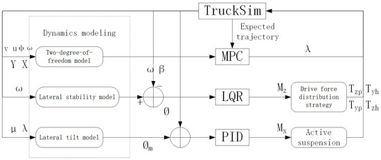
Figure 1.
Control process diagram of distributed electric drive bus.
2. Modeling of Distributed Electric Drive Bus
2.1. Vehicle Dynamic Model
To develop the trajectory-tracking and lateral stability controller for the distributed electric drive bus, a reduced-order dynamic model was established under the following simplifications [12]:
- (1)
- Operation is confined to the linear tire regime; longitudinal–lateral tire force coupling is neglected;
- (2)
- The road is assumed flat, and all vertical dynamics are disregarded;
- (3)
- To reduce model complexity, tire rolling resistance and aerodynamic drag are assumed negligible at low-to-moderate speeds.
Following these simplifications, the distributed electric drive bus is represented by the 2-DOF planar model illustrated in Figure 2.
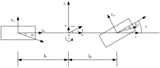
Figure 2.
Two-degree-of-freedom model.
Based on the foregoing model, the governing dynamic equations for the distributed electric drive bus—expressed in the vehicle-fixed x (longitudinal), y (lateral), and z (yaw) axes—are as follows:
where represents the total vehicle mass; is the rotational inertia of the vehicle around the z-axis; is the rotation angle of the front wheels; is the yaw angle of the vehicle; and are the distances from the center of gravity to the front and rear axles, respectively; and are the longitudinal forces exerted by the front and rear tires, respectively; and and are the lateral forces exerted by the front and rear tires, respectively [13].
Provided that tires operate within their linear regime, the force–slip relationship is linearized as
where and represent the longitudinal stiffness of the front and rear wheels of the vehicle; and represent the slip rates of the front and rear wheels; and represent the lateral stiffness of the front and rear wheels of the vehicle; and and represent the lateral deflection angles of the front and rear wheels of the vehicle [14].
Under the small-front-wheel-angle assumption, substituting Equation (2) into Equation (1) yields the reduced-order vehicle dynamics model:
The state variables are selected as , and the control variable as [15].
The above equations can be expressed in the form of state-space equations as follows:
2.2. Vehicle Lateral Stability Model
To achieve synchronous trajectory tracking and lateral stability, the controller needs to use a real-time quantifiable stability indicator as the reference benchmark. The yaw rate and the camber angle of the center of gravity can directly represent the lateral stability state of the vehicle. Therefore, a corresponding stability model must be established to analytically derive the reference values of these two parameters, providing a clear target for the stability controller [16].
When the additional yaw moment is involved, the 2-DOF lateral dynamics model of the vehicle is as follows:
where , , , and represents the additional yawing moment. Symbols follow the same notation as in Equation (1) unless otherwise specified [17].
The steady-state lateral angular velocity of the distributed electric drive bus is as follows:
Furthermore, When the tires reach the adhesion limit, they will enter the nonlinear region, causing the vehicle to lose stability. The limit value of the yaw rate is related to the adhesion coefficient, gravitational acceleration, and vehicle speed. Therefore, the reference yaw rate is constrained by the road adhesion limit as follows:
where represents the road adhesion coefficient, and represents the gravitational acceleration [18].
Then the final reference yaw rate is
Based on the stability criterion, the control objective is to ensure that the center of mass deflection angle remains zero throughout the entire process:
Taking into account the road adhesion limit and structural safety, the lateral offset angle of the center of gravity of the distributed electric drive bus should meet the following requirements:
Then the final reference centroid deflection angle is as follows:
2.3. Hub Motor Model
The hub motor eliminates the need for power transmission devices such as a gearbox, enabling it to directly transfer the output torque to the wheels [19]. The accuracy of the motor model directly affects the output of the wheel torque [20]. Since the motor itself is not the main focus of this study, this paper selects a permanent magnet synchronous motor as the drive motor for the distributed electric drive vehicle and uses the parameters of an existing motor for simulation. The basic parameters of the motor are shown in Table 1.

Table 1.
Basic parameters of the motor.
The hub motor dynamics are approximated by a second-order transfer function:
where represents the motor characteristic parameters, and represents the Laplacian operator [21].
3. Design of Trajectory Tracking Controller Based on MPC
Since the model predictive controller designed by Equation (4) has strong nonlinear characteristics, the nonlinear formulation results in high computational burden, challenging real-time implementation, which is not conducive to the rapid response of the controller [22]. Therefore, it is necessary to linearize the state-scalculationnd adopt a linear time-varying model predictive controller to improve the calculation efficiency and real-time performance.
Linearization proceeds as follows:
where represents the state matrix, indicating the partial derivatives of the system state with respect to the state variables; is the control matrix, representing the partial derivatives of the system state with respect to the control input; and is the output matrix, used to extract the output variables of the system.
The continuous-time state-space equation of the form (13) is linearized and then discretized:
where represents the discretized state matrix; represents the discretized control matrix; and represents the sampling time, which indicates the time interval for discretization.
In order to avoid the situation where there is no feasible solution during the solution process, the control increment is introduced instead of the control quantity :
Thus, the state equation of the prediction model becomes
where ; ; ; ; .
The prediction output equation of the system is as follows:
This equation is used to predict the output of the system at future times, facilitating the optimization of control inputs.
The control objective of the layered MPC is to enable the controlled intelligent vehicle to track the reference optimal value with the smallest possible deviation as quickly and smoothly as possible. Weight matrices penalize lateral deviation, yaw rate error, and control effort and relax hard constraints:
where represents the prediction time domain; represents the control time domain; represents the reference output quantity; and represents the weight matrix; and represents the weight coefficient; and represents the relaxation factor added to prevent the solution from failing.
The above control objectives and constraints were transformed into a quadratic programming problem for the solution:
where represents the optimized real symmetric matrix; k is the linear term vector; A and b are the coefficient matrix and column vector of the inequality constraints; and and represent the lower and upper limits of the control variables. The weight matrices and R are tuned via a grid-search method to minimize the integral of squared lateral error (ISE) under ISO 3888-2 maneuvers [23].
4. Design of the Lateral Stability Controller
This paper mainly studies the coordinated control of trajectory tracking and lateral stability for distributed electric drive buses. It is necessary to analyze the vehicle’s roll, pitch, and yaw motion characteristics. Among them, the lateral stability control of the vehicle is mainly reflected in the roll and yaw aspects. To achieve the stability control of distributed electric drive buses, corresponding additional yaw moments and active steering angles should be determined based on the real-time state of the vehicle.
4.1. Design of the Active Roll Control System
4.1.1. Expected Roll Angle
Current research on active anti-roll control technology for vehicles has mainly focused on two-wheel vehicles. In general, drivers will choose to increase the roll angle to utilize the component force of the vehicle and their own gravity to balance the centrifugal force exerted on the vehicle body during high-speed steering. However, for four-wheel vehicles, the structure is complex, and the actuators will limit the roll angle of the vehicle body. Therefore, a three-degree-of-freedom roll dynamics model for distributed electric drive buses needs to be established, as shown in Figure 3.
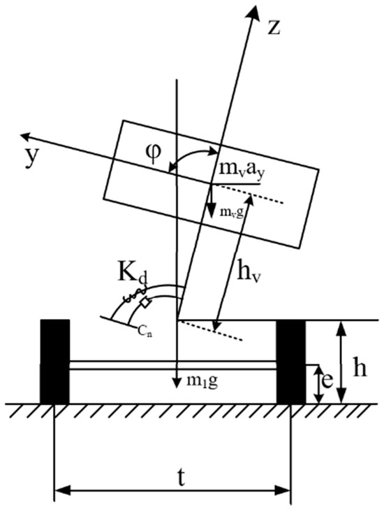
Figure 3.
A three-degree-of-freedom vehicle model considering roll motion.
The lateral roll dynamic equation of the sprung mass can be expressed as follows:
where represents the equivalent lateral stiffness of the suspension; represents the equivalent lateral damping coefficient; and represents the sprung mass.
Based on the vehicle roll motion equation, the body roll moment is generated by the body centrifugal force and the body center of gravity offset, denoted as and . The calculation equation of the body roll moment can be expressed as
where represents the side-torsion moment caused by the centrifugal force of the vehicle body; and represents the side-torsion moment caused by the deviation of the vehicle body’s center of gravity.
If the vehicle body is tilted inward towards the curve by the active suspension, the vehicle’s center of mass will deviate from the side-slip center, thereby generating an additional moment that is opposite to the side-slip moment caused by centrifugal force. This additional moment can effectively reduce the total side-slip moment of the vehicle, thereby improving the vehicle’s side-slip condition and achieving the vehicle’s anti-side-slip function.
Suppose that during the vehicle’s turning process, the vehicle body is only subjected to centripetal force, and the side-slip angle is small. At this time, if the resultant force in the y-direction is zero, then the expected side-slip angle equation for the two-wheeled vehicle can be expressed as
When applied to four-wheel vehicles, the turning radius is expressed in terms of vehicle speed and wheel angle, while taking into account the limitations of the vehicle’s actuators. The expected roll angle of the vehicle is usually within the range of to . Therefore, the following equation can be obtained:
where represents the stability factor, denotes the under-steer gradient [rad/(m·s−2)]; and is the expected body roll angle coefficient, which is related to the suspension structure limitations.
The center of gravity of the distributed electric drive bus is located at a higher position, with a large mass and volume, and the wheel spacing is relatively narrow compared to the vehicle height. Therefore, it has a lower rollover stability. During the trajectory-tracking process, when the vehicle performs roll and lateral movements, the vertical load is prone to undergo lateral transfer, which leads to rollover accidents. The lateral load transfer rate can precisely describe the vehicle’s roll state. In order to predict the vehicle’s rollover state and adjust the vehicle’s body posture in advance through vertical control to achieve stable driving, this paper takes the lateral load transfer rate as the judgment index for the rollover state of the distributed electric drive bus and predicts the numerical value of the lateral load transfer rate through the vehicle’s dynamic state.
The equation for the lateral load transfer rate is as follows:
where and represent the vertical loads of the left and right tires of the vehicle, respectively, and represents the lateral-load transfer rate.
4.1.2. Design of the Lateral Tilting Moment Controller
An active roll controller for vehicles is designed based on PID. When the vehicle enters a curve, a gyroscope measures the vehicle’s roll angle in real time and compares it with the preset target roll angle to generate an error signal, and the PID controller computes the required roll moment, which is then applied via the suspension actuator to the sprung mass and unsprung mass through the suspension actuator. By continuously adjusting the suspension moment, the centrifugal moment and the active roll moment are dynamically balanced, thereby significantly improving the roll stability of the vehicle during the turning process.
The performance of the controller is usually evaluated by response speed, steady-state error, and peak response. The PID gains are tuned using the Ziegler–Nichols method, followed by fine-tuning via MATLAB/Simulink’s PID tuner toolbox: first, a sufficiently large proportional coefficient is taken to enable the system to quickly approach the target; then, the integral coefficient is added to eliminate residual errors and suppress low-frequency oscillations; and finally, the differential coefficient is supplemented to weaken overshoot and high-frequency jitter, further enhancing stability. As shown in Figure 4, the active roll control system takes vehicle speed and front-wheel angle as inputs, and the actual roll angle as the output: the lateral sway angle velocity and lateral displacement output by the 2-DOF steering model drive the three-degree-of-freedom roll model, obtaining ; the deviation of from the desired roll angle is sent to the PID controller, and the controller generates the active roll moment according to Equation (26) and feeds it back to the three-degree-of-freedom roll model to achieve closed-loop regulation.
where represents the difference between the actual roll angle and the desired roll angle.
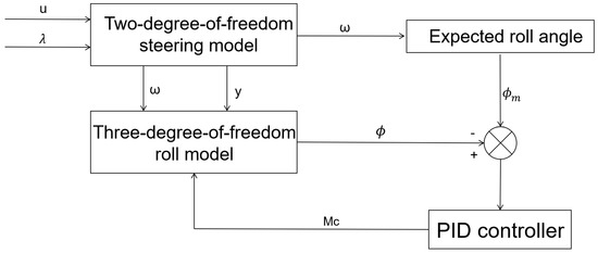
Figure 4.
Active roll control system block diagram.
4.2. Design of the Lateral Moment Controller
4.2.1. Additional Yaw Moment Decision
Under extreme operating conditions, distributed electric drive buses are highly prone to lateral skidding and instability, causing the center of gravity’s lateral deflection angle and yaw angular velocity to deviate from the ideal trajectory. Therefore, an anti-yaw moment controller based on LQR is designed to calculate the additional anti-yaw moment that needs to be applied to rapidly restore the two key state variables to their ideal values and ensure the stable operation of the vehicle. The objective function is designed as follows:
where ; ; and and are weight matrices.
The core of LQR controller design lies in determining the optimal control quantity, which must satisfy the following relationship:
where represents the optimal control quantity; and is the corresponding optimal state feedback gain matrix.
The calculation method of is as follows:
Matrix is obtained by solving the algebraic Riccati equation:
4.2.2. Drive Force Distribution Strategy
The additional yaw moment and the total driving moment of the distributed electric drive bus need to be achieved through the driving force or braking force at the wheel ends. Therefore, a wheel-end driving force distribution strategy needs to be formulated to ensure that the additional yaw moment and the total driving moment can be well realized. This paper adopts an optimization allocation strategy based on vertical load. Under any driving conditions, it first evaluates the transfer of front and rear axle loads according to the friction ellipse constraint and then couples the total longitudinal force with the additional yaw moment and distributes them to each hub motor according to the real-time axle load ratio. Thus, within the limit of not exceeding the tire adhesion limit, the upper-level control instructions can be accurately executed, and the vehicle stability can be maintained. Future work will benchmark the proposed QP against first-order methods (e.g., ADMM) to achieve sub-5 ms solver latency for real-time deployment.
The equations for the vertical loads on the front and rear axles are as follows:
where represents the road adhesion coefficient; represents the longitudinal acceleration of the vehicle; and and represent the vertical loads on the front and rear axles, respectively.
The attachment of both the front and rear axles must simultaneously meet the following requirements:
When the hub motor outputs an additional yaw moment, the relationship between the longitudinal forces of the four wheels and the moment is as follows:
where represents the wheel spacing.
By combining Equations (32) and (33), the equations for the required driving torques of each hub motor can be obtained as follows:
where represents the effective rolling radius of the tire.
Furthermore, the maximum friction force of the road surface and the limitations of the hub motor itself are as follows:
where represents the actual output torque of the hub motor; is the vertical load of the corresponding wheel; and is the peak torque of the hub motor.
5. Simulation Analysis
A joint simulation platform was established based on Trucksim and Matlab/Simulink to verify the effectiveness of the coordinated control of trajectory tracking and lateral stability. Some vehicle parameters used in the simulation are shown in Table 2. The total mass of this bus is 10,700 kg, and its yaw moment of inertia is 30,782 kg·m2. This value is basically consistent with the converted values in references [24,25] and the verification model of TtuckSim, and it meets the scaling law of similar vehicle models.

Table 2.
Vehicle parameters.
5.1. High-Speed Single-Mode Line Simulation Analysis
When a distributed electric drive bus cruising at 100 km·h−1 on a high-friction () concrete or asphalt highway detects an obstacle, it must execute an emergency avoidance maneuver or rapid lane change. To reproduce this scenario, a 10 s high-speed single-lane-change simulation is performed.
Figure 5a indicates that the vehicle can effectively follow the reference path, with the maximum lateral offset value being approximately 0.8 m. Moreover, the trajectory after control is more accurate than that of the vehicle without control. Figure 5b shows the demanded additional yaw moment, which remains within ±11 kN·m and is entirely realized through coordinated motor drive/brake torques. The front-wheel steer angle, plotted in Figure 5c, executes a −10° step for 2 s before returning smoothly to neutral, achieving a steady-state lateral acceleration of 0.6 g without overshoot. Figure 5d indicates that the lateral error peaks at 0.8 m, settles to 0.6 m, and decays to zero within 7 s, confirming high tracking fidelity. Torque allocation in Figure 5e respects the motor limits; the front hub motors consistently deliver larger absolute torques than the rear motors on the same side, demonstrating effective exploitation of available tire grip and an enlarged stability margin. Table 3 summarizes the gains: the stability controller reduces peak lateral-error metrics by 11.59–18.09% and the root mean square value (RMS) values by 8.67–14.77%. Each simulation was repeated 10 times under identical conditions; the reported metrics represent the mean ± standard deviation.
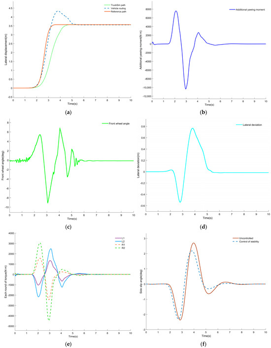
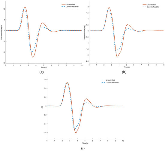
Figure 5.
Simulation results of high-speed single-turn line: (a) comparison of vehicle trajectory; (b) decision on additional yaw moment; (c) front-wheel angle; (d) lateral deviation; (e) torque distribution of each wheel; (f) comparison of center of mass camber angle; (g) comparison of yaw rate; (h) comparison of roll angle; (i) LTR comparison.

Table 3.
High-speed single-channel simulation optimization rate.
5.2. Simulation Analysis of Medium-Speed Dual-Shift Lines
Compared with the high-speed single-lane change, the 60 km·h−1 double-lane-change evaluates low-speed agility and passenger comfort. When a distributed electric drive bus traveling on a main carriageway encounters debris dropped by a preceding vehicle or any other hazard, an evasive maneuver is required. This scenario is replicated by a 12 s double-lane-change simulation at 60 km·h−1 on a high-friction () concrete/asphalt surface.
Figure 6a confirms that the vehicle is able to accurately follow the reference path, and the trajectory of the vehicle under control is more precise than that of the vehicle without control. The demanded additional yaw moment, as shown in Figure 6b, lies within ±16 kN·m, staying below the motor peak torque limit and ensuring stable operation. Figure 6c presents the front-wheel steer angle, which is commanded as a ±6° sinusoid to execute two lane changes in 2 s; the response is free of overshoot and smoothly returns to zero, maintaining a straight-ahead attitude. Figure 6d records a peak lateral deviation of ±0.08 m, with the vehicle completing the sinusoidal trajectory within 10 s and returning to the lane center without oscillation, demonstrating precise path tracking and body control. Torque allocation in Figure 6e remains within motor capability; the front hub motors consistently deliver larger absolute torques than the rear motors on the same axle, maximizing tire utilization and enlarging the stability margin. Table 4 summarizes the gains: maximum lateral metrics are reduced by 3.85–12.16% and RMS values by 4.48–11.33% after stability control.
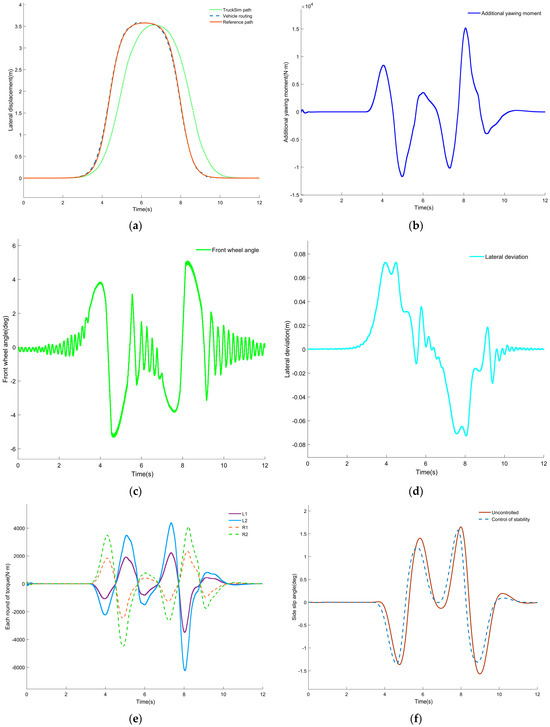
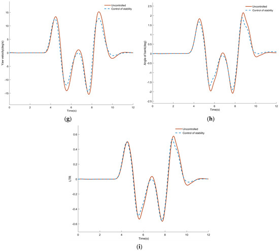
Figure 6.
Simulation results of medium-speed dual-shift line: (a) comparison of vehicle trajectory; (b) decision on additional yaw moment; (c) front-wheel angle; (d) lateral deviation; (e) torque distribution of each wheel; (f) comparison of center of mass camber angle; (g) comparison of yaw rate; (h) comparison of roll angle; (i) LTR comparison.

Table 4.
Medium-speed dual-shift line simulation optimization rate.
6. Conclusions
Based on the design of distributed electric drive buses, a coordinated control method was developed to enhance the trajectory tracking performance and lateral stability of the vehicle. The lateral stability of the vehicle was analyzed. Firstly, a trajectory-tracking controller was established to reduce the lateral error between the vehicle and the reference trajectory. Then, an active roll controller based on PID was designed, and a yaw moment controller based on LQR was also designed to make decisions on the additional yaw moment and the distribution of driving force. Finally, in the joint simulation platform of TruckSim and Matlab/Simulink, a simulated scene section was set up to verify the control method through simulation. The simulation verification results show that
- (1)
- The designed trajectory-tracking controller has a lateral deviation of approximately 22.9% in the high-speed single-shift-line operation condition and about 2.29% in the medium-speed double-shift-line operation condition. The control effect is quite good.
- (2)
- The designed stability controller makes decisions on additional yaw moments based on different operating conditions. Under the high-speed single-shift-line condition, the maximum value optimization ranges from 11.59% to 18.09%, while the root mean square value optimization ranges from 8.67% to 14.77%. Under the medium-speed double-shift-line condition, the maximum value optimization ranges from 3.85% to 12.16%, and the root mean square value optimization ranges from 4.48% to 11.33%. The control effect of the stability controller is quite good.
- (3)
- It has certain guiding significance for improving the trajectory tracking ability and lateral stability of distributed electric drive buses under extreme working conditions.
Author Contributions
Conceptualization, Y.H. and X.Z.; methodology, Y.H. and W.T.; software, Y.H.; validation, Y.H., X.Z. and T.H.; formal analysis, Y.H.; investigation, Y.H.; resources, Y.H.; data curation, Y.H. and W.T.; writing—original draft preparation, Y.H.; writing—review and editing, Y.H. and X.Z.; visualization, Y.H.; supervision, Y.H. and T.H.; project administration and funding acquisition, T.H. All authors have read and agreed to the published version of the manuscript.
Funding
This research was funded by the Innovation Fund Project of the Hubei Provincial Key Laboratory of Automotive Power Transmission and Electronic Control, grant number 2015XTZX0425.
Data Availability Statement
The original contributions presented in the study are included in the article, further inquiries can be directed at the corresponding author.
Conflicts of Interest
The authors declare no conflicts of interest.
References
- Hu, J.; Zhong, X.K.; Chen, R.N.; Zhu, L.L.; Xu, W.C.; Zhang, M.C. Intelligent vehicle path-tracking control based on fuzzy LQR. Automot. Eng. 2022, 44, 17–25+43. [Google Scholar]
- Zhang, Y.X.; Zhao, X.; Ma, J.; Wang, X.L.; Hu, Y.Q. Stability control of distributed-drive electric vehicles based on NFTSMC. J. Automot. Saf. Energy 2023, 14, 212–223. [Google Scholar]
- Lin, C.; Liang, S.; Gong, X.L.; Yu, X.; Wang, B.W. Integrated dynamics control for distributed-drive electric vehicles under extreme conditions. Automot. Eng. 2022, 44, 1372–1385. [Google Scholar]
- Du, Y.L.; Wang, X.Y.; Han, Z.L.; Wang, S.F.; Yang, J.S. Yaw stability control of distributed-drive EVs considering steering intention. J. Chongqing Univ. Technol. (Nat. Sci.) 2022, 36, 101–108. [Google Scholar]
- Li, G.; Zhang, X.; Lu, L.X. Integrated four-wheel steering and yaw-moment control for distributed-drive EVs. J. Chongqing Univ. Technol. 2023, 37, 19–28. [Google Scholar]
- Tian, J.; Zhang, C.T. Coordinated longitudinal–lateral force control for differential-steering vehicles with distributed drive. J. Chongqing Univ. Technol. (Nat. Sci.) 2022, 36, 21–30. [Google Scholar]
- Zhang, Z.Y.; Long, K.; Du, R.H.; Huang, C.X. Coordinated trajectory-tracking control for autonomous vehicles during high-speed overtaking. Automot. Eng. 2021, 43, 995–1004. [Google Scholar]
- Tang, Z.Y.; Liu, H.O.; Xue, M.X.; Chen, H.Y.; Gong, X.J.; Tao, J.F. MPC-MFAC-based trajectory tracking control for dual-motor unmanned tracked vehicles. Acta Armamentarii 2023, 44, 129–139. [Google Scholar]
- Huang, Y.G.; Luo, W.G.; Lan, H.L. Adaptive pre-aim control of driverless vehicle path tracking based on a SSA-BP neural network. World Electr. Veh. J. 2022, 13, 55. [Google Scholar] [CrossRef]
- Huang, K.Q.; Wen, S.C. Model predictive control for electric vehicle handling stability based on phase plane. Automot. Technol. 2023, 12, 47–53. [Google Scholar]
- Fu, X.; Yang, F.J.; Huang, B.; He, Z.Q.; Pei, B. Coordinated control of active rear steering and four-wheel-independent-drive vehicles. J. Jiangsu Univ. (Nat. Sci. Ed.) 2021, 42, 497–505. [Google Scholar]
- Qiu, X.; Wu, X.Y.; Chen, Z.K.; Wu, X.J. Multi-objective integrated control of active front steering and active anti-roll bar considering state estimation. Mech. Sci. Technol. 2022, 41, 386–393. [Google Scholar]
- Peng, H.N.; Tang, M.H.; Zha, Q.W.; Wang, C.; Wang, W.D. Trajectory-planning optimization for connected and automated vehicles based on inverse reinforcement learning. J. Beijing Inst. Technol. 2023, 43, 820–831. [Google Scholar]
- Lei, L.L.; Zhang, T. Longitudinal following control of intelligent vehicle platoon based on fuzzy MPC. J. Jiangsu Univ. (Nat. Sci. Ed.) 2022, 43, 394–399+430. [Google Scholar]
- Liang, Z.; Chen, Y.; Zhao, J. Real-time parameter updating and path-following control for autonomous vehicles on slope roads. Int. J. Control. Autom. Syst. 2022, 20, 2178–2190. [Google Scholar] [CrossRef]
- Jeong, D.; Choi, S.B. Tracking control using model predictive control with Laguerre functions and pole optimization. IEEE Trans. Intell. Transp. Syst. 2022, 23, 20652–20663. [Google Scholar] [CrossRef]
- Li, S.Q.; Yan, X.W.; Jin, L.T. Yaw stability control strategy for distributed-drive electric vehicles. J. Chongqing Univ. Technol. (Nat. Sci.) 2021, 35, 65–73. [Google Scholar]
- Jazar, R.N. Vehicle Dynamics: Theory and Application, 2nd ed.; Springer: New York, NY, USA, 2014; pp. 195–210. [Google Scholar]
- He, Y.X. Design of Variable Configuration and Cooperative Handling Control for Wheeled Mobile Robots. Ph.D. Thesis, Beijing University of Posts and Telecommunications, Beijing, China, 2023. [Google Scholar]
- Zhang, L.P.; Mu, J.H.; Wang, J.T.; Zhang, J.D.; Zhu, J.J. Robust predictive path-tracking control for corner-modular intelligent electric vehicles. China J. Highw. Transp. 2024, 37, 241–254. [Google Scholar]
- Li, S.; Wang, X.; Cui, G.; Lu, X.; Zhang, B. Yaw and lateral stability control based on predicted trend of stable state of the vehicle. Veh. Syst. Dyn. 2023, 61, 111–127. [Google Scholar] [CrossRef]
- Li, R.; Xiang, C.L.; Wang, C.; Fan, J.J.; Liu, C.L. Robust adaptive trajectory-tracking control for autonomous tracked vehicles. Acta Armamentarii 2021, 42, 1128–1137. [Google Scholar]
- ISO 3888-2:2011; Passenger Cars—Test Track for a Severe Lane-Change Manoeuvre—Part 2: Obstacle Avoidance. International Organization for Standardization: Geneva, Switzerland, 2011.
- Li, W.L.; Zhou, W.; Zhao, Y.K.; Zhao, L. Study on safety and compatibility of controllability and stability test and square for large bus. In Proceedings of the 4th International Conference on Sustainable Energy and Environmental Engineering (ICSEEE 2015), Shenzhen, China, 20–21 December 2015; Atlantis Press: Beijing, China, 2016; pp. 667–672. [Google Scholar]
- Sun, X.Q.; Wang, Y.J.; Cai, Y.F.; Chen, L. An adaptive nonsingular fast terminal sliding mode control for yaw stability control of bus based on STI tire model. Chin. J. Mech. Eng. 2021, 34, 79. [Google Scholar] [CrossRef]
Disclaimer/Publisher’s Note: The statements, opinions and data contained in all publications are solely those of the individual author(s) and contributor(s) and not of MDPI and/or the editor(s). MDPI and/or the editor(s) disclaim responsibility for any injury to people or property resulting from any ideas, methods, instructions or products referred to in the content. |
© 2025 by the authors. Published by MDPI on behalf of the World Electric Vehicle Association. Licensee MDPI, Basel, Switzerland. This article is an open access article distributed under the terms and conditions of the Creative Commons Attribution (CC BY) license (https://creativecommons.org/licenses/by/4.0/).