1. Introduction
High-frequency transformers used in multi-port converters are essential in the design and operation of advanced electrical systems, as they allow efficient and flexible management of multiple power flows [
1,
2]. These transformers are particularly crucial in applications such as Triple Active Bridge (TAB) converters, where the integration of multiple power sources and bi-directional transfer is imperative [
3,
4]. However, operating at high frequencies and in fast switching situations presents considerable challenges due to the generation of harmonics in the current and voltage signals measured at the transformer windings and output ports, which can compromise both component performance and lifetime [
5,
6].
In the context of power converters, harmonics are additional frequency components superimposed on the primary signal, which can cause distortions in current and voltage signals if not adequately controlled. While harmonics are often associated with signal distortion in traditional power systems, in converters, they are inherent components of switching operations, although their reduction is desirable to minimize associated losses. These distortions negatively impact conversion efficiency, increase power losses, and induce thermal stress in low-power transformers, thereby reducing the system’s long-term reliability [
7,
8,
9,
10]. In TAB converters that operate with multiple sources, these harmonics can be amplified, generating electromagnetic interference (EMI) and affecting compatibility with other electronic devices [
11,
12,
13,
14].
The generation of harmonics in multi-port converters is primarily due to the inherent nature of the switching signals (such as square and triangular waveforms), rather than the high switching frequency itself. High switching frequencies shift harmonic frequencies to higher ranges without necessarily increasing their amplitudes. On the other hand, rapid switching, characterized by the nanosecond-scale transitions of the switches, may introduce high-frequency noise but is not the primary source of harmonic generation. This distinction is essential, as the modulation and control techniques under study are designed to address harmonic components related to switching operations at the fundamental frequency, not to mitigate high-frequency noise from fast switching events.
The optimization of TAB converters significantly relies on harmonic analysis and control. The generalized harmonic approximation (GHA) technique is employed to model the instantaneous currents in the transformer windings, facilitating an accurate assessment of switching currents that contribute to device losses. This research identifies key factors influencing harmonic generation, including the parasitic capacitance of the switches, the parasitic inductance (often referred to as leakage inductance) of the transformer, switching frequency, and phase shifts within and between the full bridges [
15,
16,
17]. When these parameters are optimally regulated, they enable zero voltage switching (ZVS) operation, which reduces switching losses and enhances overall system performance by minimizing both harmonic distortion and EMI.
In addition to converter design and modulation methods, recent research has highlighted the role of intelligent control and predictive energy management in further improving efficiency. For example, Zhang et al. (2024) proposed a real-time global optimal energy management strategy for connected plug-in hybrid electric vehicles based on traffic flow information [
18]. Although such approaches fall outside the scope of this paper, they are complementary to modulation-based methods. In this work, the focus is placed on comparing SPS and DPS modulation strategies in TAB converters to assess their impact on harmonic performance and efficiency.
This paper examines the characterization and reduction in harmonics produced in multi-port transformers used in TAB converters, with a particular focus on harmonics in the currents and voltages at the windings and output ports. Harmonic generation in these transformers is influenced by magnetic coupling between the windings, core properties, and the configuration of the connected sources. A thorough investigation is conducted to analyze how variations in switching conditions, such as high frequencies and load configurations, impact harmonic distribution and amplitude. Additionally, control and design solutions are evaluated to reduce harmonic distortion, thereby improving converter performance [
19,
20,
21,
22].
The objective of this analysis is to simulate the steady-state functioning of the TAB converter and accurately predict the transformer winding currents and bridge voltages using a frequency-domain method grounded in the GHA. The application of Single-Phase Shift (SPS) and Dual-Phase Shift (DPS) control techniques on the TAB converter is thoroughly examined through two case studies: the first involves two loads at the output, and the second uses two input sources. The entire theoretical analysis is experimentally validated at a frequency of 10 kHz, with an input voltage of 110 V and an output voltage ranging from 100 V to 150 V.
2. Description of the Triple Active Bridge (TAB) Converter
TAB converter is an advanced power converter that enables bidirectional power transfer among multiple ports. This design incorporates H-bridges and a high-frequency transformer, optimizing the regulation of power distribution to the connected loads. This section analyzes two case studies: the first involving two output ports (Case I) and the second comprising two input sources and one output port (Case II).
TAB is characterized by its bidirectional power transfer capabilities, allowing power to flow in both directions among its three ports. This feature makes it an ideal choice for applications requiring the integration of various power sources or energy storage systems. The system utilizes phase modulation techniques among the bridges for precise power flow control. The implementation of zero voltage switching (ZVS) minimizes switching losses, thus enhancing system efficiency. However, ZVS operation can produce harmonics in the currents and voltages at the transformer windings and output ports, which may affect signal quality and require harmonic mitigation strategies.
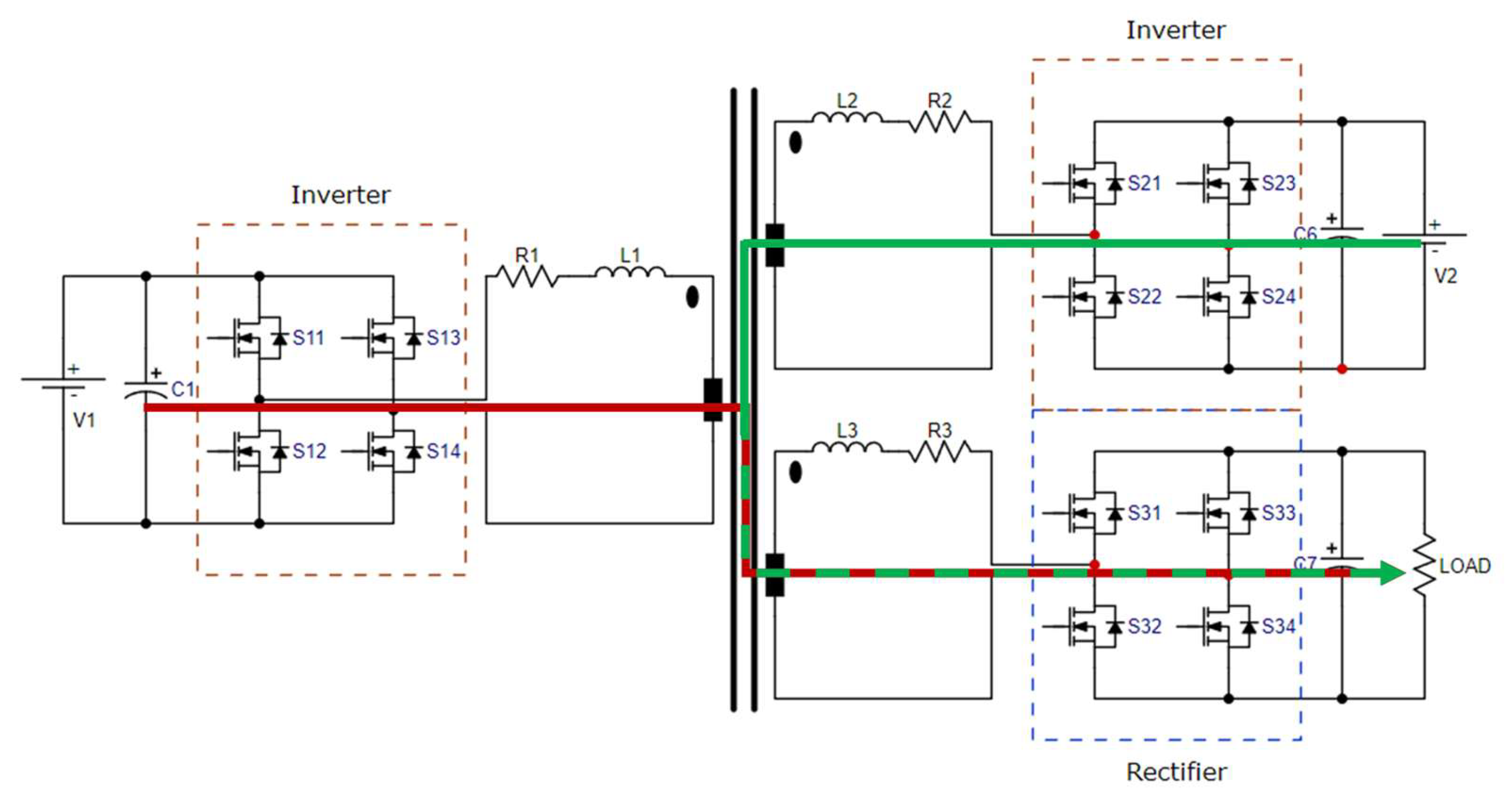
Figure 1 illustrates the TAB as depicted in Case I. On the left side of the figure is the inverter, comprising an H-bridge with switches designated
,
,
and
. This bridge transforms the direct current input signal
into a high-frequency alternating signal, which is transmitted to the high-frequency transformer positioned at the center of the diagram. This transformer comprises three windings facilitating energy distribution to the two rectifiers. Each rectifier, positioned on the right side of the figure, contains an H-bridge (
and
, whose purpose is to convert the alternating signal from the transformer into direct current, powering the two output loads linked to each rectifier.
Conversely,
Figure 2 depicts Case II, in which power allocation to the load is facilitated by the input sources
and
. The switching of the MOSFETs in the inverter stage facilitates energy transmission via the three-winding high-frequency transformer to the rectifier, thereby providing power regulation to the load. This converter is extensively utilized in high-energy efficiency applications, including smart grids, electric vehicles, and energy storage systems, owing to its versatility and capacity to efficiently manage diverse energy sources and loads.
Table 1 provides a comprehensive summary of the essential data and specifications for the design of a TAB converter. This information is crucial for modeling the converter’s behavior and understanding its performance under various operating conditions.
Modeling is a vital procedure that enables the mathematical representation of converter behavior, allowing for the investigation of its performance across diverse scenarios. In this context, the GHA method is employed to decompose the intricate waveforms produced by the converter into their harmonic constituents. This research facilitates a deeper comprehension of the impact of harmonics on signal quality and system losses.
Utilizing GHA enables the optimization of converter design, enhancing its efficiency and reliability. This technique aids in identifying distortions and facilitates the implementation of suitable strategies to alleviate them. Thus, the data displayed in the table are essential for guaranteeing the efficient and dependable functioning of the converter in real applications.
3. Mathematical Modeling of TAB
Figure 3 illustrates a comparison between the two modulation methods used in this article, the Single-Phase Shift (SPS) and the Dual-Phase Shift (DPS). In the SPS, the signals
,
, and
are phase-shifted by their designated angles (
and
) in relation to a reference signal while preserving a constant time
with power control executed only by the modulation of the phase shift among the signals. DPS introduces an extra modulation parameter (
) that modifies the pulse duration with the same
.
Table 2 highlights a comparison between simple SPS and DPS modulation strategies for the regulation of multi-port power converters. SPS provides one degree of freedom, restricted to altering the phase shift between signals, while DPS enables two degrees of freedom by manipulating both the phase shift and the pulse width, yielding enhanced control. Although SPS exhibits high efficiency, DPS can achieve superior efficiency due to its advanced capability to optimize power flow and reduce losses. Ultimately, regarding load control, SPS demonstrates less flexibility than DPS, which provides more adaptable control, making it suitable for more complex scenarios.
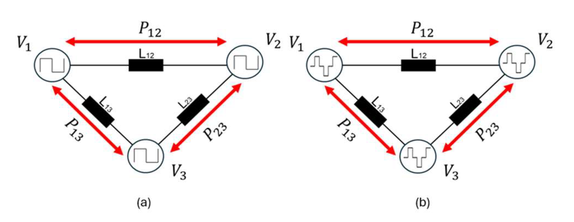
Figure 4 illustrates the power transfer under different modulation strategies. In
Figure 4a, the Single-Phase Shift (SPS) technique results in a single power flow degree of freedom, which can lead to higher circulating currents and increased harmonic content. In contrast,
Figure 4b shows the Dual-Phase Shift (DPS) modulation, where the additional control variable allows better distribution of power among the ports, reducing harmonic distortion and improving efficiency.
This diagram illustrates the three ports , and interconnected by link inductors , , and , facilitating the mathematical modeling of power transmission among the ports. The red arrows denote the power flow among the ports , and , regulated by phase modulation techniques, which are crucial for analyzing the converter’s dynamic behavior. The link inductors play a vital role in the modeling process as they formulate the equations that characterize the interaction of the bridges and the inductance losses, influencing the efficiency and harmonics of the system. SPS regulates power flow through a single-phase angle, whereas dual-phase DPS facilitates improved control across dual angles, enhancing the model for better power transfer and harmonic mitigation. The delta connection approach effectively represents converter behavior in practical scenarios, allowing for an accurate investigation of variables influencing efficiency and output signal quality.
To mathematically represent the delta connection seen in
Figure 4, it is essential to elucidate the interaction of the three inductances
,
and
. In this type of connection, each inductance is located between two voltage nodes, and the interaction between the three delta elements affects the current flow and the voltages at each port.
For sources with SPS modulation technique, the voltages are defined as (1), (2), and (3).
For sources with DPS modulation technique, the voltages are defined as (4), (5), and (6).
Assuming that
,
and
are the voltages at the corresponding nodes, and
,
,
are the currents in the inductances
,
and
, respectively, the following can be written as (7), (8) and (9).
In a delta configuration, the current at each node is the sum of the currents entering or leaving that node. Consequently, if consider each current
as flowing unidirectionally between two nodes, the currents at each node (
) must adhere to (10), (11) and (12).
These equations define Kirchhoff’s current laws for each node in the delta configuration, wherein the total current at each node equals the aggregate of the currents traversing the inductances linked to that node.
Using Equations (7)–(12), the system of differential equations that describe the behavior of the system can be represented by (13), (14) and (15).
These differential equations facilitate the simulation of the current dynamics in each inductance based on the voltage differentials between nodes. This model accurately demonstrates how the system operates under SPS or DPS phase modulation techniques. Specifically, these techniques alter the phase differences between nodes, subsequently impacting the currents in each inductance.
4. GHA-Based Modeling
In the TAB, each port produces high-frequency square signals that encompass high-frequency components resulting from fast switching cycles and implemented modulation algorithms. These signals are decomposed in the frequency domain using Fourier series. For a port
i with a square output voltage of amplitude
and a duty cycle
, the voltage can be expressed as a Fourier series:
where
n is the index of the harmonics (1, 3, 5,…), as only odd harmonics are present in a square wave.
is the amplitude of the
nth-harmonic, dependent on the duty cycle
and the voltage amplitude
. ω = 2π
f is the angular frequency of the fundamental signal.
The amplitude of the first harmonic (
) is the most significant and is calculated as (16).
The analysis of the power transfer between two ports
i and
j is carried out by examining the fundamental harmonics of the voltages at both ports. The instantaneous power
of the fundamental harmonic between ports
i and
j using SPS modulation technique is expressed as (17).
where
is the coupling inductance between the ports.
=
is the relative phase angle between the voltages of ports
i and
j.
For a DPS control approach, the transferred power can be represented by (18).
where
D is the duty cycle.
In DPS control methods, the transferred power becomes essential. Comparing the power transfer equations in SPS and DPS reveals that both regulate power flow in the TAB by altering the phase angle. However, DPS incorporates the duty cycle as an additional variable, enhancing the precision and efficacy of the control. In SPS, the phase angle solely dictates the transmitted power, simplifying the process but complicating harmonic regulation and decreasing efficiency during load fluctuations. Conversely, DPS allows modifications to both the phase angle and duty cycle, significantly reducing higher harmonics, minimizing losses, and enhancing overall system efficiency. DPS proves to be more adaptable, making it superior in high-frequency and variable-load scenarios where power management and efficiency are critical, while SPS is better in simpler systems and stable operational conditions.
The power transferred to each load in SPS in Case I is described by (19) and (20).
Due to SPS employing a constant duty cycle and phase adjustment as the sole control parameter, the transmitted power waveform displays square wave characteristics, resulting in a sequence of odd harmonics, specifically components at frequencies of , , , etc., where represents the fundamental operating frequency (10 kHz). The primary harmonic frequencies will occur at 10 kHz, 30 kHz, 50 kHz, etc.
The existence of higher harmonics in SPS negatively affects the system by producing additional conduction losses, particularly in power components such as transformers and MOSFETs, due to the extra currents generated at these frequencies. Moreover, the energy spent on these harmonics does not contribute to the usable power, thus decreasing overall system efficiency. Additionally, these harmonics modify the output waveform at loads and , introducing additional ripples that diminish signal quality.
Conversely, the power delivered to the load in Case II is determined by (21) and (22).
Since there are two input sources in Case II, the interference between their harmonics increases, resulting in intermodulation products that degrade the output signal. This harmonic interaction causes additional losses and reduces efficiency, as the energy in the higher harmonics does not directly contribute to the useful power at the load.
In both cases, DPS facilitates the regulation of power flow by adjusting both the phase angle and duty cycle at each port. In Case I, DPS mitigates greater harmonics and associated losses, enhancing power transmission efficiency and yielding cleaner, more stable output at the load terminals. In Case II, DPS is beneficial since it reduces harmonic interference among the sources, thereby decreasing intermodulation products and improving signal at the load.
In a dual-source system, each source produces its own harmonic series. When both sources are out of phase by an angle
ϕ, the resultant signal at the load includes the harmonic contributions from both sources. The aggregate signal may be expressed by (23)
5. Results and Discussion
This section evaluates the TAB converter under the two operating cases defined in Section II: Case I (one input source and two loads) and Case II (two input sources and one load). Both SPS and DPS modulation strategies are examined, with results obtained through detailed MATLAB/Simulink (v. 2024b) simulations and experimental measurements on a laboratory prototype. The analysis focuses on current waveforms, harmonic spectra, THD, and efficiency, providing a comprehensive comparison that addresses the reviewer’s concerns.
All simulations were carried out in MATLAB/Simulink with the Simscape Power Systems toolbox. The solver used was ode23tb (stiff/TR-BDF2) with a fixed step of 1 µs, sufficient to capture switching transients at the operating frequency of 10 kHz. Each run lasted 200 ms to ensure steady-state behavior before data extraction. The converter model included three full-bridge stages with SiC MOSFETs, a three-winding high-frequency transformer, and 220 µF DC-link capacitors at each port.
Phase shift modulation was implemented through dedicated control blocks that allowed switching between SPS and DPS. Measurement subsystems were integrated to record transformer currents, port voltages, harmonic spectra (via FFT blocks), and instantaneous powers. Efficiency was computed.
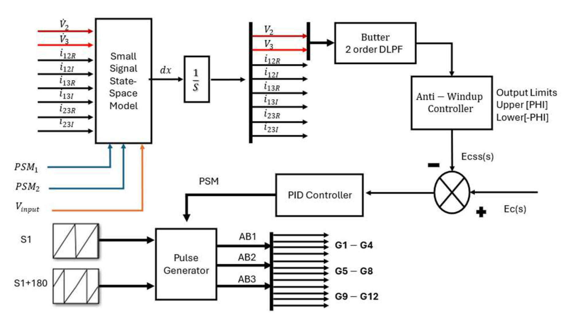
Figure 5 shows the simulation block diagram, including the small-signal state-space model, PID-based controller, and pulse-generation stage. This diagram clarifies the structure of the simulated environment, addressing the reviewer’s request for a more explicit description of the simulation setup.
To validate the simulation results, a Triple Active Bridge (TAB) laboratory prototype was implemented. The prototype consists of three full-bridge converters based on SiC MOSFET modules (C2M0080120D), a three-winding high-frequency transformer built with N87 ferrite core material and a turns ratio of 32:32:32, and DC-link capacitors of 220 µF at each port. The control signals were generated using a Texas Instruments DSP controller (TMS320F28379D LaunchPad) Texas Instruments 12500 TI Blvd., Dallas, Texas 75243, USA, programmed to implement both SPS and DPS modulation strategies.
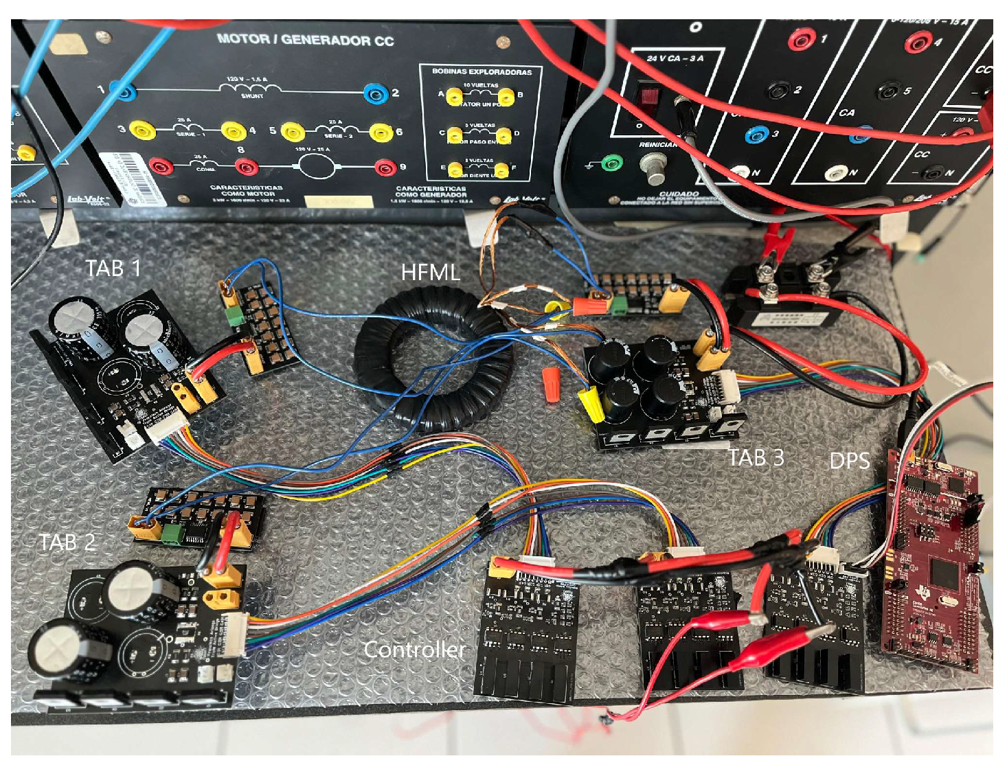
The experimental setup is illustrated in
Figure 6, where the power stage, control board, transformer, and measurement instruments can be identified. A Tektronix DPO oscilloscope with LEM current probes was used to capture the voltage and current waveforms. The prototype was operated at 10 kHz switching frequency under resistive and electronic load conditions, with a nominal DC bus voltage of 120 V per port.
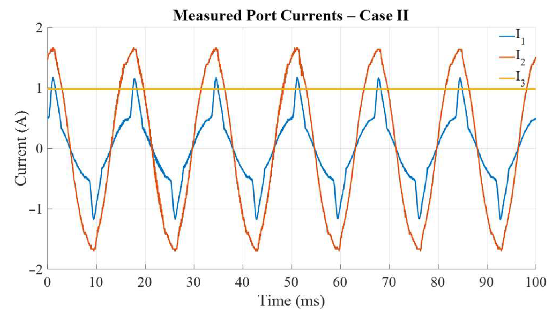
Figure 7 shows the measured port currents corresponding to Case II. In this configuration, one input port is connected to an AC source (rectified), while the second input is supplied by a regulated DC source. The third port corresponds to the load, implemented through a DC bus connected to an inverter stage. The experimental results demonstrate that under SPS modulation, circulating currents appear between the input sources, increasing harmonic content and reducing efficiency. By contrast, DPS modulation mitigates these circulating components, achieving smoother current waveforms, improved current sharing, and higher efficiency.
In Case I, the TAB converter operates with one input source supplying two output loads through the high-frequency transformer.
Figure 8 compares the input current waveforms under SPS and DPS modulation. The SPS current shows sharper transitions and higher peaks, while the DPS waveform appears smoother and with reduced distortion. This qualitative observation suggests that DPS reduces harmonic content and improves current quality.
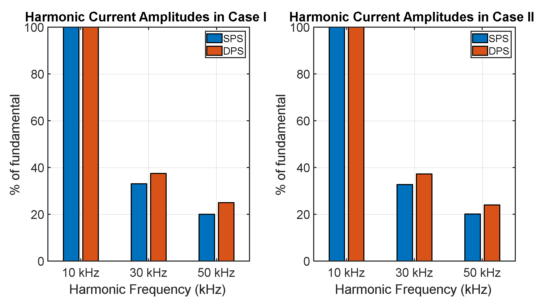
Figure 9 presents the corresponding harmonic spectra of the input current. For SPS, the spectrum is dominated by the third and fifth harmonics, leading to a total harmonic distortion (THD) of approximately 30%. Under DPS, these components are notably reduced, achieving a THD close to 15%. This corresponds to a relative reduction of nearly 50% in THD, demonstrating the effectiveness of DPS in mitigating harmonics. The improvement in waveform quality is consistent with the smoother current profiles observed in
Figure 8.
Finally,
Figure 10 summarizes the transferred power and efficiency obtained for this case. With SPS, the converter delivers 92 W at an efficiency of 81%, whereas DPS achieves similar transferred power with an efficiency of 85%. This efficiency gain of about four percentage points is attributed to the reduction in conduction losses due to lower RMS current and reduced harmonic content. Overall, the Case I results confirm that DPS outperforms SPS in both harmonic performance and efficiency, validating its advantage in one-source, two-load operation.
In Case II, the TAB converter operates with two input sources supplying a single load. This configuration is relevant for hybrid renewable-grid systems or dual-source energy storage applications, where power must be shared between two ports while maintaining stable delivery to the load. The performance under SPS and DPS modulation strategies is compared in terms of current quality, harmonic content, and efficiency.
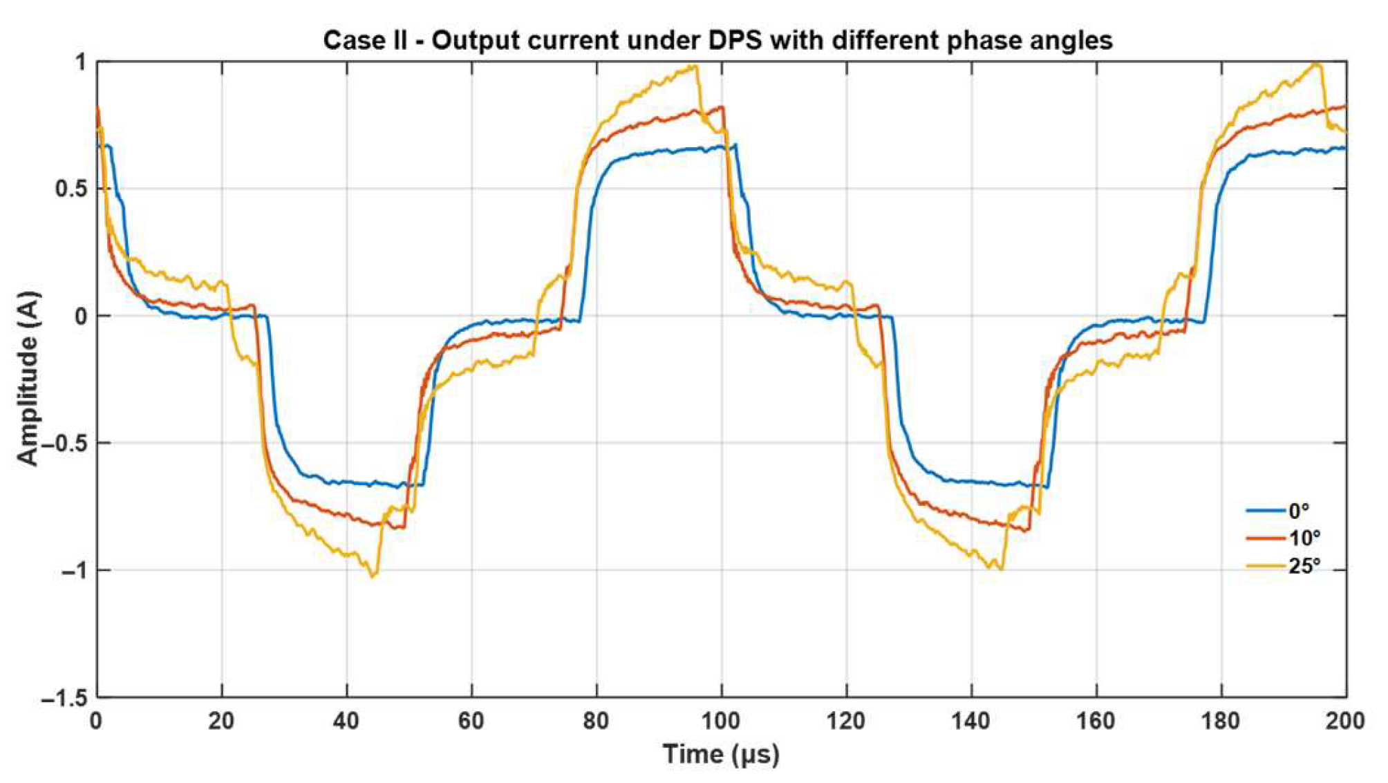
Figure 11 presents the output current waveforms obtained under DPS modulation with different intra-bridge phase angles (0°, 10°, and 25°). As the phase angle increases, the current profile becomes more distorted and peak values rise, highlighting the trade-off between controllability and harmonic distortion. In particular, 0° is equivalent to the SPS condition, whereas larger angles values correspond to full DPS operation.
It is important to clarify three complementary aspects of the reported results. First, the nominal efficiency of 85% indicated in
Table 1 refers to the design-level expectation of the converter under idealized conditions, whereas
Figure 10 and
Figure 11 present simulated and experimental efficiencies under specific operating points, which explains the slight differences between the tabulated and graphical values. Second, in
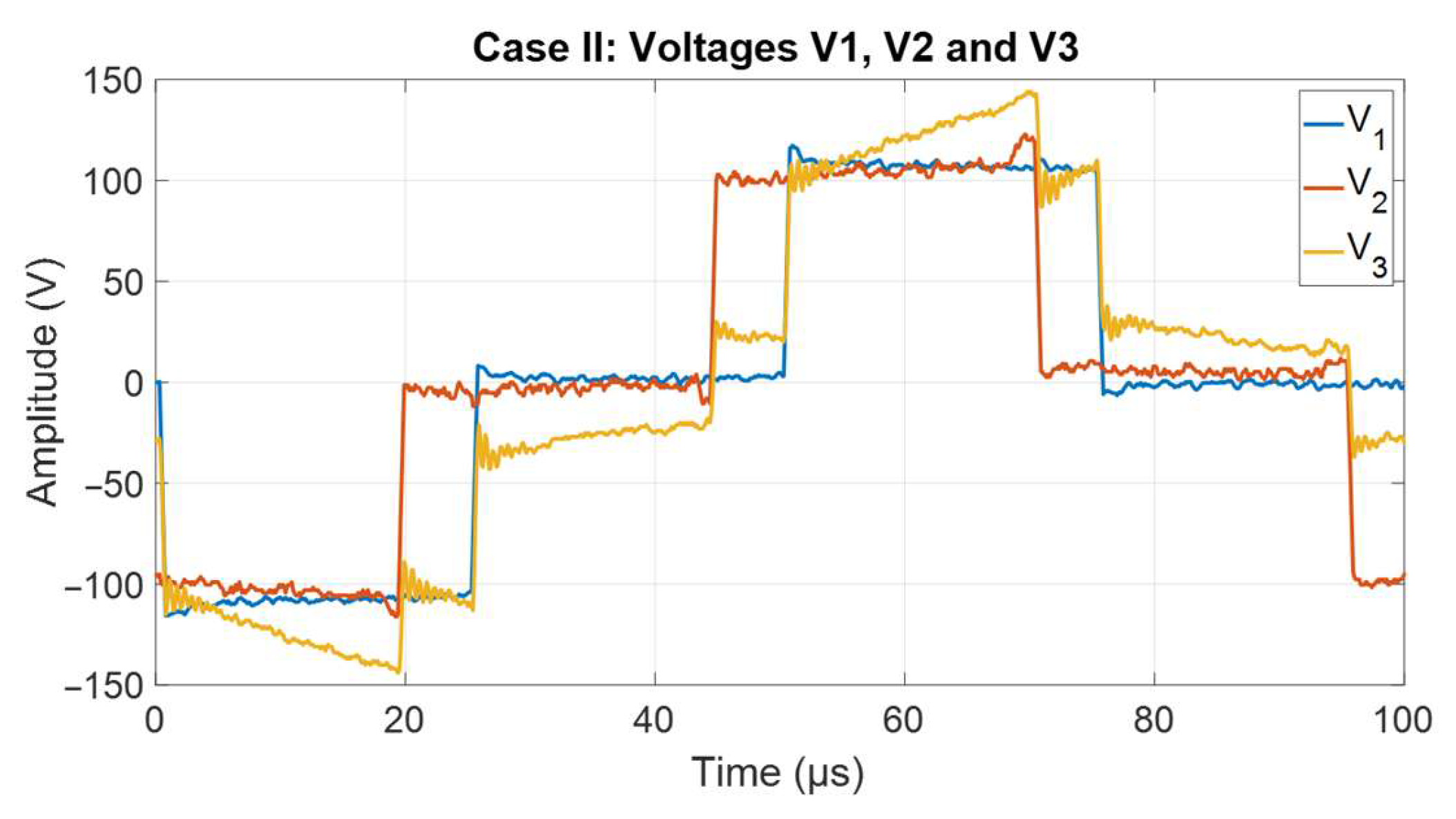
Figure 12,
and
correspond to the input source port voltages and
represents the load port voltage; the stepped profiles reflect the phase shift modulation of the TAB converter. Finally, the variation in the intra-bridge phase angle in
Figure 10 is intended to emulate changes in power-sharing and dynamic load conditions while keeping the system at nominal load, thereby illustrating the flexibility of DPS to mitigate distortion under non-ideal operating scenarios.
Figure 12 illustrates the port voltages during Case II operation. Here,
and
correspond to the two input sources, while
represents the load port. The stepped waveforms confirm the correct phase shift operation of the TAB converter, with the modulation angle determining the timing of each transition. The results validate that DPS not only improves current quality but also stabilizes the voltage delivered to the load.
Finally, the efficiency comparison in
Figure 10 shows that SPS achieves 79% efficiency at 95 W transferred power, while DPS increases the efficiency to 87% with nearly the same power. The experimental prototype confirms this trend, although absolute values are slightly lower due to non-idealities such as parasitic resistances and switching losses. Overall, the results demonstrate that DPS provides clear advantages in Case II by reducing harmonic distortion, balancing the input port currents, and improving conversion efficiency.
A comparison between Case I and Case II highlights consistent advantages of DPS over SPS across both operating modes of the TAB converter. In Case I (one source feeding two loads), DPS reduced the THD from approximately 30% to 15% and improved efficiency from 81% to 85%, ensuring a smoother distribution of power between the load ports. In Case II (two sources supplying one load), similar trends were observed, with DPS lowering THD from 28% to 16% and raising efficiency from 79% to 87%. Moreover, DPS facilitated better current sharing between the input sources, which is essential in dual-source applications. These results confirm that the additional control freedom offered by DPS consistently enhances harmonic performance, reduces conduction losses, and increases efficiency in both converter configurations, reinforcing its suitability for renewable integration, electric vehicle charging, and multi-source DC microgrids.
Beyond electrical performance, the harmonic reduction achieved with DPS also has important thermal implications. Higher harmonic currents lead to additional conduction and core losses, which translate into increased heating of passive components and energy storage systems. In electric vehicle charging infrastructures, uncontrolled harmonic currents have been shown to accelerate transformer aging and elevate thermal stress on power electronics (see [
23]). By reducing total harmonic distortion by nearly 50% compared to SPS, the DPS strategy not only enhances efficiency but also mitigates thermal risks, improving system reliability and longevity.
6. Conclusions
This study has presented a comparative analysis of efficiency and harmonic generation in multiport converters using two modulation techniques: SPS and DPS. Through simulations and theoretical analysis, it has been demonstrated that the DPS technique provides significant advantages in reducing harmonics and improving system efficiency compared to SPS.
The results indicate that in both analyzed cases, DPS effectively reduces harmonic amplitudes, particularly at the fundamental frequency, thereby minimizing harmonic distortion and enhancing output signal quality. This is clearly shown in
Figure 8 and
Figure 9, where DPS exhibits lower harmonic current amplitudes and higher efficiency in both operating configurations. The reduced distortion achieved by DPS contributes to a decrease in power losses, which translates into improved overall system efficiency. Specifically, in Case II, DPS achieves an efficiency of 87%, outperforming SPS in both study cases.
Additionally, the comparison of transferred power between the modulation techniques shows that DPS enables higher power transfer, reaching values up to 95 W in Case II. This behavior suggests that DPS is more suitable for applications requiring precise and adaptable power regulation, such as renewable energy systems, smart grids, and electric vehicles.

