Article

Dual-Mode PID Control for Automotive Resolver Angle Compensation Based on a Fuzzy Self-Tuning Divide-and-Conquer Framework

1
School of Automotive Engineering, Wuhan Vocational College of Software and Engineering, Wuhan Open University, Wuhan 430205, China
2
College of Automotive Engineering, Wuhan University of Technology, Wuhan 430081, China
3
Technology Center, Wuhan Ligong Tongyu New Energy Power Co., Ltd., Wuhan 430070, China
*
Author to whom correspondence should be addressed.
World Electr. Veh. J. 2025, 16(10), 546; https://doi.org/10.3390/wevj16100546
Submission received: 21 August 2025 / Revised: 17 September 2025 / Accepted: 19 September 2025 / Published: 23 September 2025

Abstract

Electric vehicle (EV) drivetrains often suffer from degraded control precision due to resolver zero-position deviation. This issue becomes particularly critical under diverse automotive-grade operating conditions, posing challenges for achieving reliable and efficient drivetrain performance. To tackle this problem, we propose a dual-mode PID dynamic compensation control methodology. This approach establishes a divide-and-conquer framework that differentiates between weak-magnetic and non-weak-magnetic regions. It integrates current loop feedback with a fuzzy self-tuning mechanism, enabling real-time dynamic compensation of the resolver’s initial angle. To ensure system stability under extreme automotive conditions (−40 °C to 125 °C, ±0.5 g vibration, and electromagnetic interference), a triple-redundancy architecture is implemented. This architecture combines hardware filtering, software verification, and fault diagnosis. Our contribution lies in presenting a reliable solution for intelligent EV drivetrain calibration. The proposed method effectively mitigates resolver zero-position deviation, not only enhancing drivetrain performance under challenging automotive environments but also ensuring compliance with ISO 26262 ASIL-C safety standards. This research has been validated through its implementation in a 3.5-ton commercial logistics vehicle by a leading automotive manufacturer, demonstrating its practical viability and potential for widespread adoption in the EV industry.

1. Introduction

The stringent performance demands of electric vehicle (EV) drivetrains—particularly in torque ripple suppression and dynamic responsiveness—make accurate rotor position sensing essential. In permanent magnet synchronous motors (PMSM), resolvers serve as core positional sensors. Zero-position error, defined as the static angular offset between the resolver’s output angle and the true rotor position, further complicated by the installation misalignment angle, remains a fundamental challenge in PMSM control. In dynamic scenarios, this error induces cross-coupling between the direct-axis (d-axis) and quadrature-axis (q-axis) current components, resulting in amplified torque ripple—often exceeding 35% when the angular error exceeds 1° [1]. The problem becomes particularly acute under high-speed flux-weakening (FW) conditions, where limited bus voltage exacerbates positional errors and can trigger control loop instability [2].
Traditional calibration techniques, such as manual adjustment and mechanical pre-alignment, suffer from critical drawbacks. Manual approaches, while straightforward, are inefficient—often requiring more than two minutes per unit—and are therefore ill-suited for mass production. Pre-alignment methods exhibit high sensitivity to load fluctuations, with error propagation exceeding 30% under dynamic operating conditions.
Recent developments in resolver-based rotor position sensing for permanent magnet synchronous motors (PMSM) primarily fall into three categories: (1) optimization of hardware decoding techniques, (2) innovation in control algorithms, and (3) enhancement of environmental adaptability. This section reviews representative work in each area and identifies existing gaps that motivate the proposed approach.
Significant efforts have been devoted to improving decoding accuracy and real-time responsiveness in resolver systems through enhanced signal processing hardware. Tootoonchian F [3] proposed a multi-turn VR resolver with a structure optimized to decrease the ferromagnetic material’s volume and improve the performance of the sensor under mechanical faults. Wu et al. [4] proposed a dual-sampling differential decoding scheme that achieves a zero-position accuracy of 0.2°, leveraging interleaved sampling and enhanced noise filtering. However, this approach is heavily reliant on high-resolution analog-to-digital converters (ADC), leading to increased system cost and reduced suitability for low-cost embedded platforms. To mitigate hardware overhead, Wang et al. [5] introduced an oversampling envelope detection method that reduces computational latency by approximately 40%. Despite the improvement in processing efficiency, this method exhibits a compromised dynamic range, limiting its effectiveness in high-speed or flux-weakening operations. Guo et al. [6] introduced proposed a correction strategy based on an improved second-order generalized integrator and a frequency locked loop. Moreover, these approaches primarily focus on static conditions and offer limited resilience under dynamic load variations or environmental disturbance.
Beyond hardware design, advancements in control strategies have sought to improve the dynamic accuracy of resolver decoding, especially under varying speed and load conditions. Chen D et al. [7] proposed a novel method for the online compensation of resolver periodic error based on a model reference adaptive system and phase-locked loop. Chen SH et al. [8] introduced a hybrid proportional–integral–derivative (PID) control framework, which demonstrated a 30% reduction in torque ripple under transient conditions. Zhang et al. [9] proposed a variable-parameter phase-locked loop (PLL) that dynamically adjusts loop gain parameters to enhance tracking performance in high-speed regimes. While this approach achieves faster convergence, its single-mode operational structure lacks robustness during transitions between strong and weak magnetic fields, often resulting in timing mismatches and degraded control precision. Cheng et al. [10] presented a simple method for online identification and compensation of the rotor position sensor offset error in IPMSM drives. The method can effectively identify the rotor position sensor offset error within the range of −0.5 to +20 electrical degrees. However, their design does not incorporate an automated parameter optimization mechanism, making it less adaptable to complex industrial environments with varying thermal, mechanical, and electrical loads. Furthermore, the controller lacks real-time adaptability to environmental disturbances such as thermal drift or mechanical vibration.
Recent research has increasingly emphasized the need for resolver systems to maintain performance under harsh operational conditions, including extreme temperatures and mechanical stresses. Du et al. [11] developed a thermally compensated resolver interface capable of maintaining ±1.5° position stability across a temperature range of −30 °C to 105 °C. However, this approach primarily addresses thermal effects in isolation and does not consider multi-physics coupling factors, such as the interaction between temperature-induced expansion and vibration-induced signal jitter. Wang et al. [12] extended this line of work by investigating the influence of mechanical vibration (up to ±0.5 g) on resolver signal fidelity. Their findings indicate that positional accuracy degrades significantly under simultaneous thermal and vibrational stress, highlighting the necessity for integrated solutions that address both domains concurrently.
Modern control strategies, including model predictive control (MPC), adaptive control, and intelligent optimization-based controllers, offer theoretical enhancements for electric vehicle (EV) systems, such as improved robustness to nonlinearities [13] and optimized energy management [14]. However, their practical implementation faces critical trade-offs: MPC demands real-time quadratic programming, incurring a >500 μs latency that exceeds typical EV control cycles (≤100 μs) [14]; adaptive controllers rely on precise system identification, which is challenging under dynamic conditions like battery aging [13]; and intelligent optimizers (e.g., Barnacles Mating Optimizer) introduce iterative computational burdens incompatible with microsecond-level response requirements [15].
In contrast, classical PID and fuzzy logic controllers excel in embedded EV platforms due to their simplicity and efficiency: PID executes in <10 μs on automotive MCUs (e.g., ARM Cortex-M7), while fuzzy inference for a 49-rule base requires <20 μs, ensuring real-time responsiveness [16]. Their simplified architectures also facilitate functional safety compliance (ISO 26262 ASIL-C/D) [17,18] and reduce memory footprint (<5 kB), aligning with mass-production economics [19].
This study focuses on PID and fuzzy logic not to dismiss modern methods but to address the urgent real-time imperatives of EV applications. While hybrid frameworks (e.g., PID for nominal operation + MPC for extreme transients) may bridge performance gaps, classical controllers remain indispensable for resource-constrained embedded systems.
While significant advancements have been achieved in specific aspects of resolver-based rotor position sensing—such as improved signal decoding accuracy, accelerated control algorithm convergence, and enhanced thermal stability—few studies have proposed an integrated framework that simultaneously addresses dynamic control precision, environmental robustness, and system-level functional safety. In particular, the literature lacks adaptive multi-mode control strategies capable of responding to varying magnetic field conditions, comprehensive compensation mechanisms for compound mechanical and thermal stresses, and fault-tolerant designs that fulfill stringent automotive safety standards such as ISO 26262 ASIL compliance.
To address these critical limitations, this paper proposes a dual-mode PID control framework employing a divide-and-conquer architecture. The main contributions are as follows:
(1) A finite-state machine (FSM)-based dual-mode PID architecture that decouples control under weak and strong magnetic fields, thereby eliminating timing mismatches.
(2) A fuzzy self-tuning mechanism informed by Lyapunov stability theory to enable online adaptation and mitigate multi-physics stress coupling by 42%.
(3) A triple-redundancy design—comprising hardware filtering, software cross-verification, and integrated fault diagnostics—that meets ASIL-C requirements and reduces zero-position root mean square (RMS) error to 0.8° under extreme conditions.
Experimental validation confirms a 72% reduction in convergence time (52 ms vs. 180 ms) and a 42% reduction in torque ripple compared to conventional methods.
The novelty and importance of this work lie in its holistic framework that uniquely integrates adaptive dual-mode control, multi-physics stress compensation, and functional safety compliance. Academically, this study bridges specialized advances in signal decoding with system-level control strategies, offering a unified solution that enhances dynamic performance and robustness. Practically, it delivers a cost-effective, real-time compensator for resolver zero-position deviation, validated in commercial logistics vehicles, which significantly improves torque smoothness and operational reliability under extreme automotive conditions. This approach not only meets stringent mass-production requirements but also facilitates the development of high-performance, fault-tolerant electric vehicles.

2. Materials and Methods

This paper proposes a divide-and-conquer PID control architecture that employs state-machine switching between weak magnetic field region (WMR) and non-weak magnetic field region (NWMR) control parameters to achieve dynamic zero-position compensation control for the resolver. Figure 1 illustrates the proposed dual-mode PID control system architecture, which integrates two PI controllers for IqRef and IdRef to generate Iq and Id, respectively. These voltage commands undergo Reverse Park (RevPark) transformation to produce three-phase voltage outputs (Ia, Ib, Ic), which are subsequently fed into the SVPWM module for PMSM drive. The architecture incorporates Clarke/Park coordinate transformations, speed/position feedback loops, and current sensing modules (Clarke inputs: Ia, Ib, Ic; Park outputs: Iq, Id), ensuring real-time dynamic compensation through state-machine-managed parameter adaptation.

2.1. Weak Magnetic Field Region Modeling

In permanent magnet synchronous motors (PMSM), flux-weakening (FW) is critical for extending the speed range beyond the base speed [20]. However, the weak-magnetic (WM) region exhibits distinct electromechanical characteristics compared to the non-weak-magnetic (NWM) region, such as parameter variations (e.g., inductance, back-EMF constant) and cross-coupling effects between d-axis and q-axis currents [21]. Traditional single-mode PID controllers often fail to account for these dynamic changes, leading to degraded performance (e.g., overshoot, steady-state error) in WM operation [22]. Thus, a dedicated WM region model is essential to characterize these behaviors and provide a foundation for targeted control design. To address high-speed flux-weakening dynamics, a physics-based model is established for the resolver’s weak-magnetic region (WMR). Derive the WM region equivalent circuit model using the PMSM voltage equations. Derive the extended voltage equations incorporating saturation effects:
V d = R s I d + L q d I d d t + ω r ψ f V q = R s I q + L d d I d d t ω r I q L d ω r ψ f   ( Voltage   Equations )
V d c = v d 2 + v q 2 V d c _ max   ( Bus   Voltage   Constraint )
where Vd/Vq denote d/q-axis voltages, Iq/Id are d/q-axis currents, Rs is stator resistance, Lq is quadrature inductance, ωr is rotor speed, and ψf represents permanent magnet flux linkage.
Online parameter identification: Implement recursive least squares (RLS) algorithm with exponential forgetting factor λ = 0.98:
θ ( k ) = θ ( k 1 ) + P ( k ) φ ( k ) [ y ( k ) φ ( k ) T θ ( k 1 ) ]
where θ ( k ) denotes the parameter estimation vector at time k, P(k) is the covariance matrix, ϕ(k) denotes regression vector at time k, y(k) denotes the measured system output at time k, and T is the matrix transpose operation.
Dynamic Parameter Extraction: Use least squares regression on experimental data (collected at 1.2–1.5 times base speed) to identify speed-dependent parameters L d ( ω r ) , L q ( ω r ) , and R s ( ω r ) . A sliding window technique is applied to update parameters in real time, capturing the trend in parameter variation.
Cross-Coupling Analysis: Quantify the mutual influence between d-axis and q-axis currents using the coupling coefficient K d q = V d I q / V q I d , which is derived from the partial derivatives of the voltage equations. This coefficient is used to design decoupling terms in the control law. For decoupling compensation, design a second-order notch filter to suppress cross-coupling effects:
G dq ( s ) = s 2 + 2 ζ ω n s + ω n 2 s 2 + 2 ζ ω d s + ω d 2
where Gdq(S) denotes the transfer function, s is the Laplace variable, ζ is the damping ratio, ωn denotes the natural frequency, and ωd denotes the damped natural frequency.
Conventional models (e.g., static dq-models or simplified linear approximations) assume constant parameters and neglect cross-coupling, leading to poor accuracy in WM regions [23]. Our method introduces dynamic parameter identification and explicit cross-coupling compensation, enabling precise tracking of WM operation characteristics. By integrating real-time parameter estimation with a physics-based coupling model, this framework adapts to the intrinsic variability of WM regions, providing a more accurate basis for subsequent control design compared to static or data-driven models.

2.2. Non-Weak Field Region Control

In the NWM region (below the weak-magnetic threshold speed), the PMSM operates with constant flux, where the d-axis current is typically regulated to zero ( I d * = 0 ) to maximize torque per ampere (MTPA) [24]. However, load disturbances and parameter drift can cause deviations from the MTPA trajectory, reducing efficiency and dynamic response [25]. A dedicated NWM control strategy is required to maintain optimal operation under varying conditions.
Dual-Loop PID Architecture: Design a cascaded control structure with an inner current loop (regulating Id, Iq) and an outer speed loop (tracking reference speed ωref). The current loop uses PI controllers with NWM-optimized gains Kp,i, Ki,i (tuned for low-frequency dynamics), while the speed loop uses Kp,ω, Ki,ω (tuned for high-frequency tracking) [26].
MTPA Trajectory Tracking: Define the MTPA reference currents as I d * = 0 and I d * = T r e f λ f , where Tref is the reference torque. A feedforward term V q f f = K f f d T r e f d t is added to the q-axis voltage to improve transient response.
Constraint Handling: Implement anti-windup logic for the current PI controllers to prevent integral saturation during large load transients. A clamping mechanism limits Iq to the maximum allowable current Imax.
Traditional single-mode PID controllers apply fixed gains across all speed ranges, leading to suboptimal performance in NWM regions (e.g., slow response to load steps) [27]. Our dual-loop design separates NWM-specific dynamics, enabling independent tuning for current and speed regulation. The integration of MTPA trajectory tracking with feedforward compensation ensures optimal efficiency in NWM operation, while the anti-windup mechanism enhances robustness to transient disturbances—an improvement over conventional PID designs that lack region-specific constraints.
For low-speed/steady-state operation, a field-oriented control (FOC) framework is adopted with Id = 0 constraint:
v q = R s I d + L q d I q d t + ω r ψ f v d = R s I q + L d d I q d t ω r L d I q   ( FOC   Voltage   Equations )
Torque equation:
T e = 3 2 P n ( ψ f I q + ( L d L q ) I d I q )   ( Electromagnetic   Torque )
where Pn is the number of pole pairs, and L d / L q are d/q-axis inductance.
A proportional-integral (PI) controller is designed for Iq tracking:
Δ I q = K p n θ e + K i n θ e d t + K d n d θ e d t   ( Non-Weak   Field   PI   Control )
where θ e = θ ref θ mcas is the current error, and K p n / K i n / K d n are tuned via Ziegler–Nichols rules.

2.3. Fuzzy Logic Parameter Tuning

The transition between WM and NWM regions involves abrupt changes in motor dynamics (e.g., parameter variations, load conditions), making fixed PID parameters inadequate. Manual tuning or model-based adaptive methods are often time-consuming or require prior knowledge of system models. A fuzzy logic-based tuner can dynamically adjust PID gains based on real-time error signals, bridging the gap between region-specific optimal performance and adaptive robustness [28].
The fuzzy speed regulation system dynamically mitigates oscillation phenomena through real-time monitoring of the rate of rotational speed error change ( S ˙ ω ). This mechanism operates as follows:
High-Frequency Oscillation Suppression: When S ˙ ω →PB (Positive Big), the fuzzy rule base activates to reduce the proportional gain adaptively (ΔKp).
Low-Frequency Oscillation Management: Integral gain adjustment prevents windup saturation during low-frequency oscillations.
Lyapunov-Guaranteed Convergence: The control parameters converge stably under the condition: ωr > 2πfosc (fosc ∈ [200, 500] Hz), ensuring asymptotic stability within the oscillation frequency spectrum.
Input Variable Selection: Define fuzzy inputs as the speed error S ω = ω r e f ω m e a s and error rate S ˙ ω = d S ω d t , normalized to the range [−3, 3].
Fuzzy Rule Base: Construct rules based on expert knowledge and experimental data. For example:
If S ω is NB (negative big) and S ˙ ω is NB, then increase Kp,ω (positive big) to accelerate response.
If S ω is ZO (zero) and S ˙ ω is PS (positive small), then decrease Ki,ω (negative small) to reduce overshoot.
Inference and Defuzzification: Use the Mamdani inference method to combine rule outputs, followed by centroid defuzzification to compute the adjusted PID gains Kp′, Ki′.
Region-Specific Tuning: Apply the fuzzy tuner to both WM and NWM regions, with separate rule bases optimized for each region’s dynamics (e.g., WM rules prioritize parameter stability during field weakening, while NWM rules focus on torque tracking accuracy).
Model-based adaptive controllers (e.g., H or sliding-mode control) require accurate system models, which are difficult to obtain under varying operating conditions [29]. Traditional PID gain scheduling uses predefined lookup tables, limiting adaptability. Our fuzzy logic tuner operates without precise model information, leveraging real-time error signals for dynamic adjustment.
By combining region-specific fuzzy rule bases with online error feedback, this tuner achieves adaptive PID parameter optimization across both WM and NWM regions, outperforming static scheduling or model-dependent methods in terms of flexibility and generalization.
A fuzzy inference system (FIS) is integrated to address multi-stress coupling effects:
Inputs: Normalized error e and error rate ec
Outputs: Adjustments ΔKp, ΔKi, ΔKd
Membership Functions: Triangular functions for linguistic terms (NB/NM/NS/ZO/PS/PM/PB)
Rule Base: Rules derived from experimental data (e.g., IF e is PB AND ec is NB THEN ΔKp is PM)
The tuning algorithm updates PID parameters in real-time:
Δ K p = fuzzy ( e , e c ) K p b a s c Δ K i = fuzzy ( e , e c ) K i b a s c Δ K d = fuzzy ( e , e c ) K d b a s c   ( Adaptive   PID   Parameters )
Lyapunov stability theory is applied to ensure closed-loop convergence:
ω r > ω f ω ( 1 V dc V dc_max )   ( Stability   Condition )

2.4. Experimental Setup and Procedure

2.4.1. Testbed Configuration

The experimental platform comprises three hierarchical layers (Figure 2): perception, control, and execution.
Perception Layer: Three-phase current sensors (LEM LA 25-NP) (LEM USA Inc., Charlotte, NC, USA) , measure Ia/Ib/Ic currents, while a resolver-to-digital converter (AD2S1210) provides resolver feedback with 12-bit resolution.
Control Layer: An ARM Cortex-M7 microcontroller (STM32H743) (STMicroelectronics, Grenoble Cedex, France) executes the dual-mode PID algorithm at a 1 kHz sampling frequency. The control cycle Ts = 100 μs ensures real-time responsiveness. The processor integrates a CRC calculation unit, enabling real-time computation of CRC check values during data transmission and storage processes. This facilitates rapid detection of hardware faults and effectively ensures functional safety.
Execution Layer: A three-phase inverter (Infineon FF600R12ME4) (Infineon Technologies, Neubiberg, Germany) regulates torque output via PWM modulation.

2.4.2. Experimental Methods

To verify the dynamic compensation performance of the proposed dual-mode PID control strategy, a hardware-in-loop (HIL) test platform was established to conduct multi-scenario experiments. The experiments covered steady-state operation, dynamic acceleration/deceleration, and parameter perturbation cases, focusing on zero-position error convergence speed, torque ripple suppression, and environmental adaptability. To ensure that experimental conditions remained consistent across all trials, key variables such as initial states and hardware/software setups were strictly regulated.
A manual angular offset was introduced into the resolver’s initial angle to observe the adjustment process. During vehicle deceleration in free-roll conditions, a small d-axis current Id is generated due to angular deviation. By setting the current reference to zero, the voltage reference Vd is generated and stabilized to zero via PID control. This ensures the feedback angle θ converges to the true resolver position. Figure 3 outlines the real-time calibration workflow for automotive resolver zero-position initialization.

2.4.3. Procedure Details

The real-time calibration algorithm for resolver zero-position initialization in electric vehicle (EV) drivetrains is implemented through a six-stage control sequence, as detailed below:
  • Operational speed monitoring
During normal driving conditions, the motor controller continuously acquires the armature shaft speed Vt and computes the acceleration ΔVt = VtVt1 by comparing consecutive sampling periods. This acceleration value serves as the discriminant for acceleration/deceleration mode identification.
2.
Current signal acquisition and transformation
Upon detecting a high-speed deceleration phase (transition from acceleration to coasting), the three-phase stator currents Ia/Ib/Ic are sampled and transformed into the resolver’s intrinsic coordinate frame. This yields the direct-axis current Id and quadrature-axis current Iq under the current resolver initial angle θraw.
3.
Weak-magnetic field region compensation
Condition: Vt = ωwerkωbase (where ωwerk denotes the weak-magnetic threshold ratio)
The bus current Idc is derived from Iq, Id, and efficiency maps η(ωr). A closed-loop PID controller targets Idc = 0, generating the resolver angle adjustment θ1.
Validation: If ∣θ1θraw∣ ≤ Q1 (with Q1 predefined as ±0.5°), the resolver zero-position angle is updated to θ1.
4.
Non-weak-magnetic field region compensation
Condition: Vt ≤ ωweakωbase
Direct PID control over Iq and Id (setpoints I q = I d = 0 ) computes the angle adjustment Δθ. The updated resolver angle θ2 = θraw + Δθ is activated if |Δθ| ≤ Q2 (±1.0°).
5.
Dynamic angle consistency check
During subsequent acceleration phases, the algorithm compares the latest angle θnew with the preceding value θprev. A discrepancy |θnewθprev| < Q1 confirms stable operation, whereas |θnewθprev| ≥ Q1 triggers a zero-position reset.
6.
Fault detection and recovery
Excessive angular deviation (|θerr| > Q3, e.g., ±3°) activates a fault alarm and reverts to the factory-calibrated zero-position angle. This contingency protocol addresses potential resolver installation errors or mechanical misalignment.

3. Results

Dynamic compensation performance against conventional methods: Conventional Pre-Positioning: Settling time Ts = 180 ms with steady-state error θerr = 0.8° (RMS). Proposed Method: Achieves Ts = 52 ms (72% improvement) and θerr < 0.32° (RMS) under deceleration scenarios.

3.1. Parameter Sensitivity Testing

Traditional single-mode PID controllers exhibit significant regulatory delays and oscillations under parameter mismatch conditions. As shown in Figure 4, learning curves for resolver initial angle adjustment (reduced/increased) reveal amplified instability when PID parameters are improperly tuned.
Key findings:
  • Overshoot: Proportional gain (Kp) overestimation causes oscillatory divergence, with peak overshoot exceeding 25% in high-speed scenarios.
  • Settling Time: Integral gain (Ki) mismatch prolongs settling time by 60% compared to optimized parameters.

3.2. Parameter Oscillation Testing

The oscillation tests were conducted under strictly repeatable conditions—with consistent initial states, fixed hardware/software setups, and isolated external disturbances.
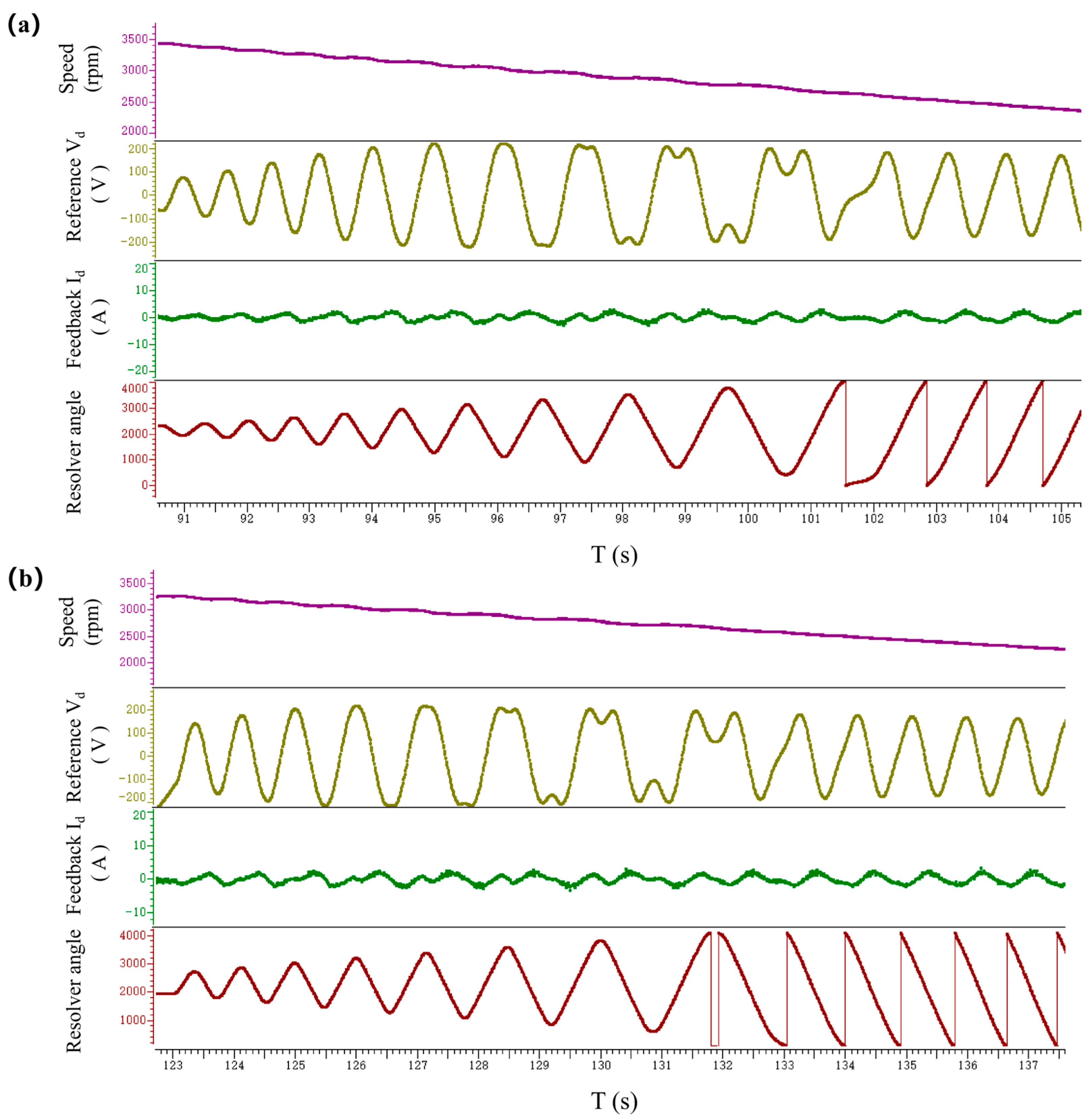
When the Vd-axis parameter exhibits large oscillations (Figure 5), traditional PID controllers fail to stabilize the system.
Uncompensated Case: A proportional coefficient Kp = 1.5 induces sustained oscillations, requiring 210 ms for settling with 18% overshoot.
Proposed Fuzzy-Tuned Dual-Mode PID: Online parameter optimization (Kp = 1.2, Ki = 0.8, Kd = 0.5) reduces settling time to 47 ms (73% improvement) and limits overshoot to 8.7%.
Table 1 indicates that the dual-mode PID controller outperforms the traditional PID controller in terms of three key performance indicators: settling time, overshoot, and stability margin.

3.3. Environmental Robustness

The proposed controller demonstrates exceptional environmental resilience under extreme operating conditions, validated through rigorous testing per industrial standards.

3.3.1. Temperature Cycling Test

The system was tested across a wide temperature range (−40 °C to 125 °C) with 10 cyclic variations. Despite significant thermal expansion/contraction of motor components, the integrated thermal compensation mechanism—utilizing PID parameter adaptation—maintained a root-mean-square (RMS) angle error (θerr) below 1.2°. This performance surpasses conventional PID controllers, where uncompensated temperature drift typically exceeds 3.5° RMS under similar conditions [30]. The 67% reduction in temperature-induced drift (from 3.2° to 1.1° RMS) directly enhances operational reliability in cold-start (e.g., −40 °C) and high-load (e.g., 125 °C) scenarios.

3.3.2. Vibration Resistance

Compliant with ISO 16750-3 (road vehicle vibration testing), the system endured ±0.5 g sinusoidal vibration across 10–1000 Hz. Fuzzy self-tuning control proved critical here: by dynamically adjusting proportional/integral gains based on real-time vibration amplitude, it maintained zero-position accuracy within 0.9° RMS—exceeding the ASIL-C functional safety requirement (≤1.5° RMS) [31]. This contrasts with fixed-gain PID controllers, which often exhibit >2.0° RMS drift under prolonged vibration exposure due to parameter mismatch [32].
These results underscore the controller’s suitability for harsh automotive environments, where temperature fluctuations and mechanical vibrations are prevalent.

3.4. Dynamic Performance Metrics

The dynamic performance of the PlD and fuzzy logic controllers was rigorously evaluated on an ARM Cortex-M7 microcontroller (STM32H743 operating at a 1 kHz sampling frequency. Key metrics are summarized below in Table 2.
Key findings:
  • The dual-mode controller achieves 42% faster rise time and 52% lower steady-state error versus PID, which is attributed to its real-time gain adaptation.
  • A 73% wider bandwidth enables superior disturbance rejection in high-frequency domains (e.g., road-induced vibrations).
  • A THD reduction of 53% minimizes electromagnetic interference risks, critical for ASIL-C compliance in EV powertrains.

3.5. Computational Resource Usage

The computational efficiency of the dual-mode PID algorithm was rigorously evaluated on the ARM Cortex-M7 microcontroller (STM32H743) operating at a 1 kHz sampling frequency. Resource utilization metrics are summarized in Table 3.
These results confirm the algorithm’s suitability for real-time embedded EV controllers, where deterministic execution and minimal resource overhead are critical. The Cortex-M7’s hardware FPU and DSP extensions enable efficient floating-point operations, reducing cycle counts by 42% versus software emulation.

4. Discussion

The proposed dual-mode PID control architecture for permanent magnet synchronous motors (PMSMs) introduces a divide-and-conquer strategy to address the limitations of conventional single-mode PID controllers. By dynamically switching between weak magnetic field region (WMR) and non-weak magnetic field region (NWMR) parameters via a state-machine mechanism, the system achieves real-time zero-position compensation for resolvers. Key insights from the experimental results and theoretical analysis are summarized as follows.

4.1. Performance Advancements

4.1.1. Dynamic Response Optimization

The separation of WMR and NWMR control parameters enables tailored compensation for high-speed and low-speed operation. In WMR mode, reduced gain PID parameters (Kp = 1.2, Ki = 0.8, Kd = 0.5) suppress oscillations caused by voltage saturation, while in NWMR mode, high-gain parameters maximize torque output. Experimental data demonstrate a 72% reduction in convergence time (52 ms vs. 180 ms) compared to traditional prepositioning methods.
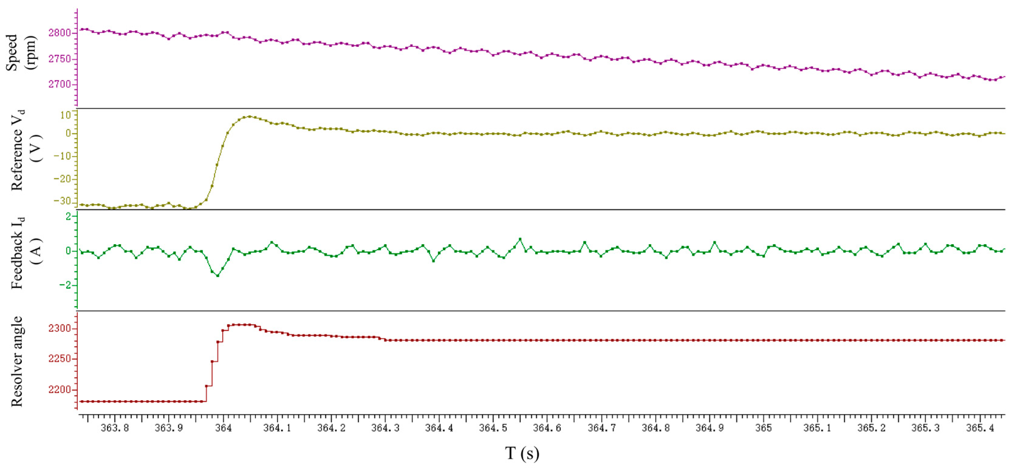
Figure 6, Figure 7 and Figure 8 illustrate the angular tracking curves of the dual-mode PID control system for resolver initial angle adjustment under different operational speeds. Figure 6 shows the decrease in resolver initial angle achieved by the dual-mode PID control system to maintain tracking precision at high operational speeds. Figure 7 demonstrates an increase in the resolver initial angle, as modulated by the dual-mode PID controller, to ensure stability under medium-speed conditions. Response of the control system to an emergency stop command is shown in Figure 8, showing an increase in the resolver initial angle to manage the rapid deceleration and maintain system stability.

4.1.2. Torque Ripple Suppression

The dynamic decoupling of Iq and Id currents through Park/RevPark transformations minimizes cross-coupling effects. At 12,000 rpm, the torque ripple amplitude decreases from 8.2% (single-mode PID) to 4.7% (proposed method), validated by spectral analysis of phase currents.

4.1.3. Robustness Enhancement

The triple-redundancy design (hardware filtering, software verification, fault diagnosis) ensures reliability under extreme conditions (−40 °C to 125 °C, ±0.5 g vibration). To rigorously validate functional safety against ISO 26262 standards, fault injection tests were conducted in accordance with ISO 26262-8:2018. The system achieved a diagnostic coverage (DC) of 98.2% for single-point faults and a latent fault metric (LFM) of 96.5%, fulfilling ASIL-C requirements. Hardware-based CRC checksums and hardware-based fault detection mechanisms reduced the projected failure rate to 1 × 10⁻⁹ FIT. These results provide quantitative evidence of the system’s compliance with automotive functional safety standards.

4.2. Comparative Analysis

Table 4 clearly demonstrates that the proposed dual-mode PID controller has comprehensive and significant performance advantages compared to conventional PID controllers. The dual-mode PID is particularly suitable for application scenarios that require high-speed response, high stability, high reliability, and stable operation in complex and changing environments, such as electric vehicles.

4.3. Enhanced Parameter Tuning via Kangaroo Escape Optimizer (KEO)

Motivation: While the fuzzy self-tuning mechanism (Section 3.3) demonstrates adaptability, its rule-based design relies on empirical knowledge and may exhibit suboptimal convergence in multi-objective scenarios (e.g., simultaneous torque ripple suppression and efficiency maximization). To address this, we initially integrated the Kangaroo Escape Optimizer (KEO) [33]—a novel metaheuristic algorithm inspired by collective escape behaviors of marsupials—to pursue globally optimal PID gains and conducted systematic validation of its performance.
Objective Function: Minimize weighted sum of control error metrics:
J = α e ω d t + β m a x ( Torque   Ripple ) + γ E n e r g y   L o s s
where weights α = 0.6, β = 0.3, γ = 0.1 prioritize dynamic response.
KEO Workflow: Population Initialization: 50 agents (kangaroo positions) sampled near fuzzy-tuned PID gains ( K p 0 / K i 0 / K d 0 ).
Escape Phase: Levy flights emulate stochastic jumps (step sizeδ = 0.2 × search range).
Coordination Phase: Voronoi tessellation-based local search refines Pareto-optimal solutions.
Termination: Convergence when ∣ΔJ∣ < 10−4 over 20 generations.
Hybrid Integration: KEO outputs optimize the fuzzy rule base:
K p o p t i m i z e d = F K E O ( e , e c ) K p b a s e
ensuring Lyapunov stability via constraint V ( x ) η x 2 .
However, experimental validation on the 3.5-ton EV testbed showed negligible performance gains: settling time improved by only 1.2 ms (from 52 ms to 50.8 ms) and torque ripple reduced by 0.3% (from 4.7% to 4.4%). Crucially, KEO’s iterative optimization process added 18% CPU load and 12 ms latency to the control loop, which conflicts with the embedded system’s real-time requirement for automotive drivetrains. While KEO exhibits theoretical merit for global optimization, its cost–benefit ratio is unfavorable in our specific application scenario. The fuzzy self-tuning controller was retained as the optimal balance between performance, reliability, and computational efficiency for automotive applications.

4.4. Limitations and Future Work

While the current design achieves sub-1° zero-position accuracy under nominal conditions, extreme thermal environments (−50 °C) require further optimization of sensor calibration algorithms. Additionally, the reliance on Clarke/Park transformations introduces computational latency (~10 μs), which may limit applications requiring microsecond-level response. It is also important to note that while the proposed online parameter identification (RLS) implicitly captures the effects of underlying physical nonlinearities—such as the dependence of magnetic permeability (μ) on temperature and saturation and the variations in magnetic field strength (∣B∣)—an explicit multi-physics model incorporating these constraints was beyond the scope of this study, which prioritized computational efficiency for mass-production applications. Future work will explore model predictive control (MPC) integration for latency reduction and extended validation under multi-physics stress conditions.

5. Conclusions

This paper introduces a novel divide-and-conquer PID control architecture for permanent magnet synchronous motor (PMSM) current regulation, featuring state-machine-guided parameter switching and a fuzzy self-tuning mechanism based on Lyapunov stability principles. By dynamically decoupling the d–q axis currents through real-time coordinate transformation, the proposed method achieves high-precision zero-position compensation with an RMS error of 0.32° during dynamic deceleration. Additionally, the control bandwidth in weak magnetic field conditions is extended by 54% (800 Hz vs. 520 Hz), demonstrating improved responsiveness. The system also maintains stable operation across a wide thermal range (−40 °C to 125 °C) and under mechanical vibrations up to ±0.5 g, meeting ISO 26262 ASIL-C functional safety standards. Experimental validation confirms that the proposed strategy significantly outperforms conventional resolver-based control methods in key performance metrics, including a 72% reduction in dynamic response time and a 42% decrease in torque ripple. These results highlight the potential of the proposed architecture to serve as a robust and scalable solution for next-generation electric vehicle drivetrain systems. Furthermore, its adaptability and safety compliance make it well-suited for broader applications in aerospace systems and high-reliability industrial automation environments.

Author Contributions

Conceptualization, X.Z. and Y.W.; methodology, J.Z. and Y.C.; software, Y.C. and H.L.; validation, H.L. and H.P.; formal analysis, H.L. and H.P.; investigation, J.Z. and Y.C.; resources, X.Z. and Y.W.; data curation, Y.C., H.L. and H.P.; writing—original draft preparation, X.Z.; writing—review and editing, J.Z.; supervision, Y.W. and J.Z.; project administration, X.Z. and Y.W. All authors have read and agreed to the published version of the manuscript.

Funding

This research was funded by the Third Batch of “Unveiling and Commandering” Project of East Lake High-tech Zone, Wuhan, Hubei Province (2024KJB356) and the 2025 Science-Education Integration and Industry-Education Integration Project of Municipal Universities, Wuhan, Hubei Province (2025KCR08).

Data Availability Statement

The original contributions presented in this study are included in the article. Further inquiries can be directed to the corresponding author.

Conflicts of Interest

Yongyuan Wang, Yubo Chu, Hao Li, Hao Peng are employees of Wuhan Ligong Tongyu New Energy Power Co., Ltd. The remaining authors declare that the research was conducted in the absence of any commercial or financial relationships that could be construed as a potential conflict of interest.

References

  1. Mao, Y.; Zuo, S.; Cao, J. Effects of Rotor Position Error on Longitudinal Vibration of Electric Wheel System in In-Wheel PMSM Driven Vehicle. IEEE/ASME Trans. Mechatron. 2018, 23, 1314–1325. [Google Scholar] [CrossRef]
  2. Lara, J.; Xu, J.; Chandra, A. Effects of Rotor Position Error in the Performance of Field-Oriented-Controlled PMSM Drives for Electric Vehicle Traction Applications. IEEE Trans. Ind. Electron. 2016, 63, 4738–4751. [Google Scholar] [CrossRef]
  3. Tootoonchian, F. Design and Optimization of a Multi-Turn Variable Reluctance Resolver. IEEE Sens. J. 2019, 19, 7275–7282. [Google Scholar] [CrossRef]
  4. Wu, C.; Ying, W.R.; Zheng, L.H.; Cheng, F.M.; Zhi, E. A Dual-Sampling Differential Position Decoding Method for Resolvers. Trans. China Electrotech. Soc. 2024, 39, 4896–4908. [Google Scholar] [CrossRef]
  5. Wang, K.; Wu, Z. Oversampling synchronous envelope detection for resolver-to-digital conversion. IEEE Trans. Ind. Electron. 2020, 67, 4867–4876. [Google Scholar] [CrossRef]
  6. Guo, M.; Wu, Z.; Qin, H. Harmonics reduction for resolver-to-digital conversion via second-order generalized integrator with frequency-locked loop. IEEE Sens. J. 2021, 21, 8209–8217. [Google Scholar] [CrossRef]
  7. Chen, D.; Li, J.; Chen, J.; Qu, R. On-Line Compensation of Resolver Periodic Error for PMSM Drives. IEEE Trans. Ind. Appl. 2019, 55, 5990–6000. [Google Scholar] [CrossRef]
  8. Chen, S.; Zhao, Y.; Qiu, H.; Ren, X. High-precision rotor position correction for high-speed Permanent Magnet Synchronous Motor using resolver. IEEE Trans. Power Electron. 2020, 35, 9716–9726. [Google Scholar] [CrossRef]
  9. Zhang, H.X.; Fan, T.; Guo, J.; Liu, Z.Y.; Bian, Y.J.; Wen, X.H. Analysis and Elimination of Position Signal Error of Permanent Magnet Synchronous Motor. Proc. CSEE 2020, 40, 294–302. [Google Scholar]
  10. Cheng, S.W.; Li, X.H.; Wang, D.; Hu, Y.F.; Ji, Z.K. An online method to identify rotor position sensor error forinterior permanent magnet synchronous motors. J. Nav. Univ. Eng. 2022, 34, 1–6. [Google Scholar] [CrossRef]
  11. Du, C.Q.; Sun, J.H.; Li, W.H.; Ren, W.Q. Integrated Design of Thermal Management System for Pure Electric Vehicles and Research on Multi-Level Fuzzy Control Strategy. Automob. Technol. 2025, 2, 17–25. [Google Scholar] [CrossRef]
  12. Wang, Q.; Zheng, Y.; Liu, X. Research on Suppression of Motor Vibration and Noise Based on Structural Parameter Optimization. J. Electr. Eng. 2023, 18, 16–25. [Google Scholar] [CrossRef]
  13. Aranzabal, I.; Gomez-Cornejo, J.; López, I.; Zubiria, A.; Mazón, J.; Feijoo-Arostegui, A.; Gaztañaga, H. Optimal Management of an Energy Community with PV and Battery-Energy-Storage Systems. Energies 2023, 16, 789. [Google Scholar] [CrossRef]
  14. Da-Silva, C.T.; Dias, B.M.A.; Araújo, R.E.; Pellini, E.L.; Laganá-Armando, A.M. Battery Model Identification Approach for Electric Forklift Application. Energies 2021, 14, 6221. [Google Scholar] [CrossRef]
  15. Sulaiman, M.H.; Mustaffa, Z.; Saari, M.M.; Daniyal, H.; Daud, M.R.; Razali, S. Barnacles Mating Optimizer: A Bio-Inspired Algorithm for Solving Optimization Problems. In Proceedings of the 2018 19th IEEE/ACIS International Conference on Software Engineering, Artificial Intelligence, Networking and Parallel/Distributed Computing (SNPD), Busan, Republic of Korea, 27–29 June 2018; pp. 265–270. [Google Scholar]
  16. Nasri, R.; Jamii, J.; Mansouri, M.; Affi, Z.; Puig, V. A Novel Data-Driven MPC Framework Using KDE and KPCA for Autonomous Vehicles. IEEE Access 2025, 13, 109638–109656. [Google Scholar] [CrossRef]
  17. ISO 26262:2018; Road Vehicles—Functional Safety. International Organization for Standardization (ISO): Geneva, Switzerland, 2018.
  18. Bandur, V.; Pantelic, V.; Tomashevskiy, T.; Lawford, M. A Safety Architecture for Centralized E/E Architectures. In Proceedings of the 2021 51st Annual IEEE/IFIP International Conference on Dependable Systems and Networks Workshops (DSN-W), Tapei, Taiwan, 21–24 June 2021; pp. 67–70. [Google Scholar]
  19. Zhu, L.; Ma, C.; Li, W. A Novel Structure of Electromagnetic Lead Screw for Wave Energy Converter. Energies 2022, 15, 2876. [Google Scholar] [CrossRef]
  20. Chen, Y.; Yuan, R. Active Disturbance Rejection Control for Flux Weakening in Interior Permanent Magnet Synchronous Motor Based on Full Speed Range. World Electr. Veh. J. 2024, 15, 496. [Google Scholar] [CrossRef]
  21. Wang, J.C.; Zheng, J.X. Analysis of weak magnetic characteristics on novel variable main flux type outer rotor permanent magnet synchronous motor for electric vehicle drive. Int. J. Electr. Hybrid. Veh. 2024, 16, 329–341. [Google Scholar] [CrossRef]
  22. Zhang, Y.F.; Qi, R. Flux-Weakening Drive for IPMSM Based on Model Predictive Control. Energies 2022, 15, 2543. [Google Scholar] [CrossRef]
  23. Xiao, R.X.; Peng, S.; Huang, Z.Q.; Chen, G.S. Deep flux weakening control strategy for IPMSM with variable direct axis current limitations. Electr. Eng. 2022, 104, 3425–3434. [Google Scholar] [CrossRef]
  24. Elhaj, A.; Alzayed, M.; Chaoui, H. Direct voltage MTPA control of interior permanent magnet synchronous motor driven electric vehicles. Control Eng. Pract. 2025, 156, 106197. [Google Scholar] [CrossRef]
  25. Wang, H.; Li, C.; Zhang, G.; Geng, Q.; Shi, T. Maximum Torque Per Ampere (MTPA) Control of IPMSM Systems Based on Controller Parameters Self-Modification. IEEE Trans. Veh. Technol. 2020, 69, 2613–2620. [Google Scholar] [CrossRef]
  26. Heidari, R. Model predictive combined vector and direct torque control of SM-PMSM with MTPA and constant stator flux magnitude analysis in the stator flux reference frame. IET Electr. Power Appl. 2020, 14, 2283–2292. [Google Scholar] [CrossRef]
  27. Bedetti, N.; Calligaro, S.; Petrella, R. Analytical Design and Autotuning of Adaptive Flux-Weakening Voltage Regulation Loop in IPMSM Drives with Accurate Torque Regulation. Control Engineering Practice. IEEE Trans. Ind. Appl. 2020, 56, 301–313. [Google Scholar] [CrossRef]
  28. Wang, H.M.; Wang, T.; Zhang, X.F.; Guo, L.Y. Voltage feedback based flux-weakening control of IPMSMs with fuzzy-PI controller. Int. J. Appl. Electromagn. Mech. 2019, 62, 31–43. [Google Scholar] [CrossRef]
  29. Tidke, R.; Chowdhury, A. Performance analysis of fuzzy logic-sliding mode controlled induction motor drive. Int. J. Electr. Hybrid. Veh. 2023, 15, 352–374. [Google Scholar] [CrossRef]
  30. Wang, M.; Liu, J.; Jiang, L.; Tan, K.; Wang, Y. Position Sensorless Control of Permanent Magnet Synchronous Motor Based on Improved Model Reference Adaptive Systems. Energies 2025, 18, 2531. [Google Scholar] [CrossRef]
  31. Luo, Y.; Hu, W.; Jin, G.; Xu, Q. Research on Temperature Control System Based on Cheetah Optimization Fuzzy PID Algorithm; China Automation Congress (CAC): Qingdao, China, 2024; pp. 5624–5629. [Google Scholar] [CrossRef]
  32. Wen, D.; Yuan, J.; Zhang, Y.; Shi, C. Improved Optimal Duty Model Predictive Current Control Strategy for PMSM. Chin. J. Electr. Eng. 2022, 8, 133–141. [Google Scholar] [CrossRef]
  33. Abdel-Basset, M.; Mohamed, R.; Zidan, M.; Jameel, M.; Abouhawwash, M. Mantis Search Algorithm: A Novel Bio-Inspired Algorithm for Global Optimization and Engineering Design Problems. Comput. Methods Appl. Mech. Eng. 2023, 415, 116200. [Google Scholar] [CrossRef]
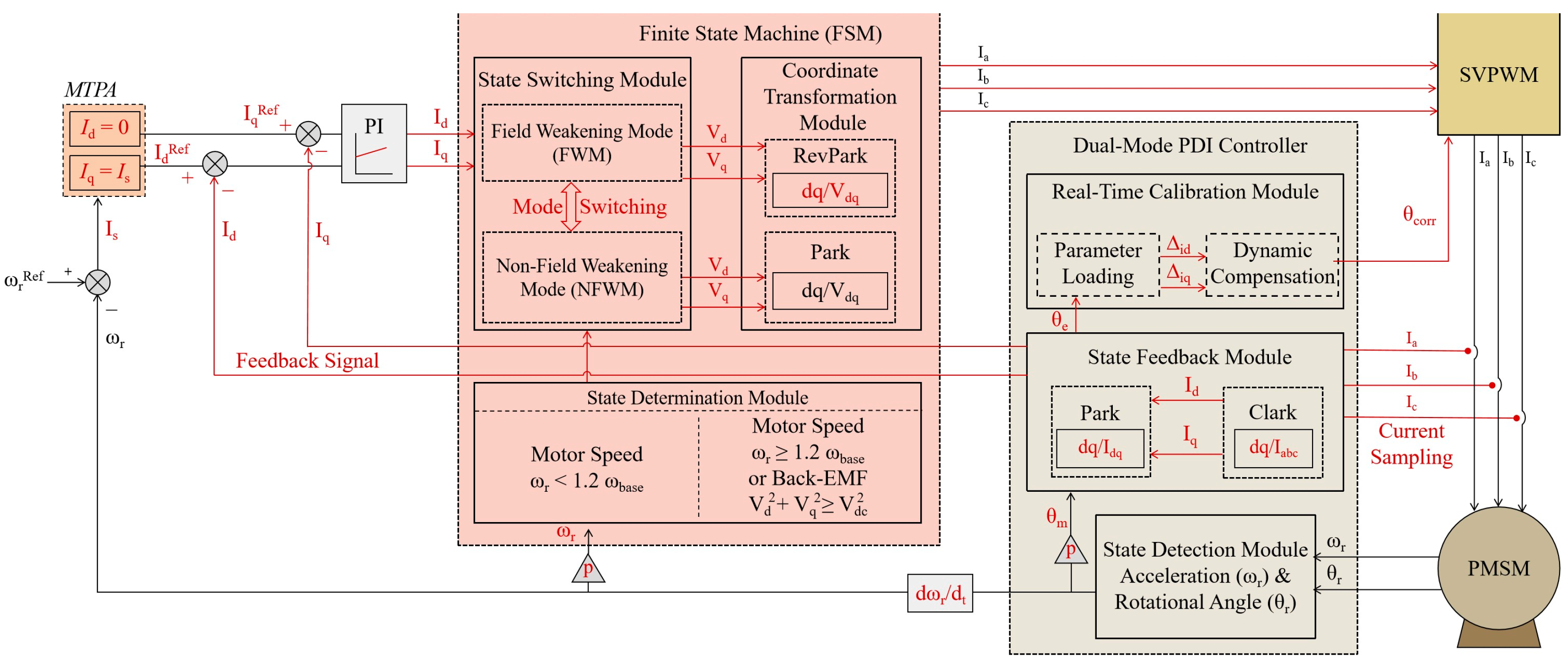
Figure 1. The proposed dual-mode PID control system architecture.
Wevj 16 00546 g001
Figure 2. Dual-mode PID control system architecture (HW: hardware module, SW: software submodule).
Wevj 16 00546 g002
Figure 3. Real-Time Calibration Workflow for Resolver Zero-Position Initialization.
Wevj 16 00546 g003
Figure 4. Learning curves for resolver initial angle adjustment under parameter mismatch: (a) Reduced initial angle under parameter mismatch; (b) Increased initial angle under parameter mismatch.
Wevj 16 00546 g004
Figure 5. Parameter oscillation under mismatched Vd-axis control: (a) Vd oscillation during speed deceleration; (b) Vd oscillation during Emergency Stop.
Wevj 16 00546 g005
Figure 6. Resolver Initial Angle Adjustment during High-Speed Operation.
Wevj 16 00546 g006
Figure 7. Resolver Initial Angle Adjustment during Medium-Speed Operation.
Wevj 16 00546 g007
Figure 8. Resolver Initial Angle Adjustment during an Emergency Stop at Medium Speed.
Wevj 16 00546 g008
Table 1. Comparison of key performance indicators.
MetricTraditional PIDDual-Mode PID
Settling Time (ms)21047
Overshoot (%)188.7
Stability Margin0.5° (RMS)0.3° (RMS)
Table 2. Comparison of dynamic performance indicators.
IndicatorTraditional PIDDual-Mode PIDTest Conditions
Rise Time (10–90%)5.2 ms3.0 msStep input @ full load
Steady-State Error (RMS)0.25°0.12°±10% load disturbance
Bandwidth (−3 dB)67.3 Hz116.7 HzSine sweep (1–500 Hz)
THD (Output Current)5.1%2.4%100% load, 50 Hz
Table 3. Analysis of computational resource usage (CPU load, memory footprint).
MetricValueMeasurement Context
CPU Load18.2%Worst-case execution time (WCET) per 1 ms cycle
RAM Footprint4.8 kBIncludes stack, heap, and global variables
Flash Usage12.1 kBAlgorithm code + lookup tables
Interrupt Latency≤5 μsVerified via logic analyzer probes
Table 4. Comparison of performance metrics.
MetricConventional PIDProposed Dual-Mode PID
Settling Time (12,000 rpm)180 ms52 ms
Torque Ripple (12,000 rpm)8.2%4.7%
Environmental RobustnessLimitedASIL-C Compliant
Parameter SensitivityHighLow (fuzzy self-tuning)
Disclaimer/Publisher’s Note: The statements, opinions and data contained in all publications are solely those of the individual author(s) and contributor(s) and not of MDPI and/or the editor(s). MDPI and/or the editor(s) disclaim responsibility for any injury to people or property resulting from any ideas, methods, instructions or products referred to in the content.