Article

FPGA-Based VFF-RLS Algorithm for Battery Insulation Detection in Electric Vehicles

1
Department of Electrical and Electronics Engineering, Manipal Institute of Technology Bengaluru, Manipal Academy of Higher Education, Manipal, Udupi 576104, India
2
Department of Electrical Engineering, Malaviya National Institute of Technology, Jaipur 302017, India
3
Department of Computer Science and Engineering, Manipal Institute of Technology, Manipal Academy of Higher Education, Manipal, Udupi 576104, India
*
Authors to whom correspondence should be addressed.
These authors contributed equally to this work.
World Electr. Veh. J. 2024, 15(4), 129; https://doi.org/10.3390/wevj15040129
Submission received: 3 February 2024 / Revised: 5 March 2024 / Accepted: 12 March 2024 / Published: 22 March 2024

Abstract

:
As the adoption of electric vehicles (EVs) continues to rise, attention has switched to ensuring the safety of EV operations. The exponential growth in battery technology over the past several years has changed the face of energy storage and sparked a revolution in several industries. The degradation of battery insulation during regular use is a significant concern. The high voltage (HV) and current levels in HV electric vehicles pose a significant electrical threat.The advancement of electric vehicle technology has led to an increasing presence of HV electric equipment throughout the vehicle. The insulation strength and early health status detection of the batteries are essential in ensuring safety in EVs. This paper studies the different insulation detection techniques and the development of adaptive filter (AF) algorithms based on field-programmable gate arrays (FPGAs) for insulation detection. FPGAs are amongst the most accurate and fast detection techniques among all the insulation detection techniques used so far in electric vehicles. This study proposes an FPGA-based VFF-RLS algorithm for effectively implementing insulation detection in EVs. The experimental test results using FPGAs demonstrate that the proposed method can rapidly monitor changes in insulation resistance (IR). The VFFRLS-based FPGA technique works sufficiently well to reduce errors when dealing with variations in voltage and resistance conditions at the battery terminals.

1. Introduction

As a result of the growing number of environmental issues on a worldwide scale and the ongoing energy crisis, electric mobility has become increasingly significant and prevalent in recent times. In an effort to develop alternatives to the fossil fuels that are currently being used, society is looking for more sustainable and clean forms of energy. The utilization of renewable energy by using e-mobility is seen as a viable alternative [1,2,3,4]. In the past few decades, lithium-ion (Li-ion) batteries have demonstrated significant advancements in their performance as the primary energy storage component of EVs. In the meantime, automobile manufacturers are introducing an increasing number of battery-electric vehicles (BEVs), while government agencies and business organizations are working to construct additional charging infrastructure. The advancement of electric vehicle technology has led to an increasing presence of HV electric equipment throughout the vehicle [5,6,7,8,9]. Consequently, the voltage level within the vehicle has also experienced enhancements, thereby elevating the significance of electric HV safety. When insulation materials lose their ability to insulate, resistance can go down. This can be dangerous for EVs because it can shorten the battery life or even cause a fire. Therefore, for early detection of insulation status, it is essential to be aware of the factors that can cause insulation breakdown and take appropriate measures to prevent it. Such factors include overload, contamination, aging, physical damage, voltage stress, temperature, and environmental issues like line aging and rain erosion, which might diminish the system’s insulation and cause it to fail [10,11,12,13,14]. Figure 1 shows how these factors impact the battery’s insulation. An increasing amount of attention is being paid to the safety of Li-ion batteries used in EVs. Insulation plays a very significant part in ensuring the safety of electrical systems.
However, the available insulation detection techniques for EV insulation resistance, including comprehensive detection and fault location, are inadequate for meeting the growing demands for EV insulation detection. The large-scale power battery module poses a significant risk to the safety system, particularly the insulation [15,16,17]. As a result, accurate and fast monitoring of faults in insulation is crucial to the secure functioning of the system. Reports in the literature have suggested different detection algorithms for IR in DC systems [18,19,20]. The power battery of a pure EV has the properties of elevated voltage and substantial current. Monitoring the IR between the positive and negative power batteries and the vehicle’s chassis is required for continuous evaluation of the insulation performance of EVs. The IR of an EV is defined as if there is a short circuit between the power BP of the vehicle and the ground (the chassis of the vehicle), and the resistance corresponds to the maximum leakage current [21,22,23]. Currently, there are many methods for offline and online sensing of the IR of the vehicle power battery, such as direct measurement methods, bridge measurement methods, and signal injection methods. Figure 2 shows the different types of insulation detection methods available.
Offline insulation direct detection systems use the voltmeter and megohmmeter methods. Voltmeter measurements are only accessible offline. It is necessary to detach the battery case from any external electrical equipment throughout the measurement. The complexity of this procedure precludes its online implementation [23,24,25]. Electrical measuring tools that use megohms are common. Most megohmmeters use hand-cranked “shake meters” or generators. A hand-cranked generator and magnetoelectric ratio meter make up the megohmmeter. The megohmmeter makes high-voltage alternating current by shaking the handle to power the hand-cranked generator, then it sends out HVDC for measurement through diode rectification and uses the magnetoelectric ratio meter to measure the voltage and current of the coil current ratios. The pointer indication shows the resistance scale. The megohmmeter measures current by exciting the device or network under test with voltage, then using Ohm’s law to calculate the resistance. The drawbacks of this technique are the small voltage and range; errors are more common. The operation is complex, and the voltage output is unstable. Due to the significant reverse impulse current, improper pointer-type megohmmeter operation during turn-off can harm the pointer [26,27,28]. The online insulation detection includes the utilization of both balanced and unbalanced bridge approaches. The bridge-balanced system is a constant measurement system. It is not applicable in situations where both bilateral IRs decrease simultaneously. Additionally, it frequently results in erroneous alerts when there is a significant drop between the positive and negative insulating resistance. References [18,25,29] introduce an innovative detection technique that utilizes an unbalanced bridge. This method effectively addresses the limitations of the balanced bridge approach. This approach can accurately identify the insulation resistance even if the bilateral insulation resistances decrease simultaneously. In order to provide accurate measurements, it is essential to often change the resistance used for measurement. Additionally, the unilateral voltage requires a specific amount of time to settle after each switch. Furthermore, the hardware of the device is highly intricate. The circuit is highly susceptible to noise interference due to its intricate operating circumstances, resulting in a reduction in the system’s detection correctness. Hence, the immediacy of this approach is insufficient. References [18,19,20,30] present a system for detecting insulation resistance using the current detection method. The online insulation detection techniques include low-signal and high-signal injection methods. These researchers have chosen the low-signal injection method because it worked well with the chosen detection system. They also suggested signal injection methods for monitoring insulation to avoid having voltage changes affect the results of the measurements. The signal injection system determines the insulating resistance of the BP by introducing a current or voltage signal and analyzing the resulting feedback signal. References [18,31] introduce a method for detecting insulation via direct-current injection. Adding current through injection, on the other hand, could be dangerous to the system. This shows a way to find insulation by sending a square-wave voltage signal and using the Lyapunov observer to estimate the insulating resistance. References [21,32,33,34] propose a filtering algorithm as an insulation detection strategy to enhance the system’s capability to handle noise. We examined the unscented Kalman filter (UKF) and the extended Kalman filter (EKF) [26] to estimate the IR using the voltage injection model. This approach enhances the precision of the detection outcomes. The determination of the process and evaluation noise in these two algorithms is challenging, thereby restricting their use. References [27,28,29,35] introduce a method for detecting IR that addresses the issue of parameter adjustment. This method utilizes an RLS algorithm. The presence of a constant forgetting factor in RLS hinders its ability to adapt to the abrupt change in the insulating resistance. Based on the findings in this paper, we developed a VFF-RLS method that utilizes FPGA technology to rapidly detect insulation.

Contribution of This Study

After conducting a thorough literature review [18,19,20,21,22,23,24,25], we created four distinct conditions based on battery terminal voltage and resistance and analyzed the errors in the detection system, the accuracy, and the response. In the literature, insulation resistance theory is used to identify the battery’s insulation, which functions as high resistance between the vehicle power battery and the chassis to prevent current from contacting the chassis [28,29,30,31,32]. Insulation detection is frequently achieved by the use of adaptive filtering (AF) systems, such as RLS, LMS, and VFF-RLS. While all three algorithms aim to reduce the difference between the expected and observed outputs by modifying the filter coefficients, their techniques and potency levels differ. The VFF-RLS approach has to a greater extent an advantage over the LMS algorithm [32,33,34,35,36,37,38,39,40,41]. The VFF-RLS algorithm converges quicker than the other two algorithms, making it suited to scenarios requiring rapid adaptation to changes in the input data. When developing AF algorithms, FPGAs provide various advantages, including parallel processing, which allows multiple jobs to be executed simultaneously. This is advantageous for AF algorithms because it enables parallel computing of the coefficients of the filter, resulting in the quickest processing intervals. FPGAs are more flexible and let programmers develop AF algorithms that meet unique requirements. This flexibility is useful for adapting the hardware to the algorithm’s features, potentially lowering the power absorbed and improving the best performance.
This study looked at existing VFF-RLS algorithm methods and created an FPGA-based VFF-RLS algorithm to test the IR of vehicle battery HVDC systems. The goal was to make existing VFF-RLS-based algorithm methods more accurate, faster, more stable, and better at blocking interference. This method has the advantage of fast response speed. The FPGA technique improved the response time to 2 s, while also providing high robustness, high evaluation accuracy, and strong anti-interference ability. These features make it suitable for promotion in EVs. This work presents an FPGA-based system for detecting insulation failure in real time. We verified the accuracy of the FPGA outcomes by comparing them to the Matlab simulation results found in the current literature. Significant reductions in errors occurred in the FPGA results; thoroughly explain the enhanced results from the FPGA in the results and discussion section. In addition, in this study, we developed a hardware experimental platform using FPGA technology and performed a range of experiments on electric vehicles using motor and resistive loading. These experiments were undertaken to confirm the effectiveness of the FPGA method proposed.
The article is organised in the following manner: The design methodology is introduced in Section 2, along with a general discussion of the battery circuit model and insulation detection analysis, and introduction to the FPGA and VFF-RLS algorithms. Section 3 provides a detailed discussion of an experimental module and the simulation results. Section 4 presents the conclusions.

2. Design Methodology

The battery pack is constructed with many cells connected in series and parallel to fulfill the required voltage load. Insulation failure may occur at each cell due to cable ageing or rain erosion. The battery insulation detection equivalent circuit model, which employs a low-frequency signal injection method in the battery pack, is depicted in Figure 3. The diagram presents the essential configuration of an electric vehicle’s high-power supply, comprising the battery circuit module, inverter, motor, disconnectors, and vehicle chassis. Previous studies have examined the origins of the HV system [12,13,14]. The voltage, resistance values, and insulation resistance counting model of the battery are taken into account as input values for the simulation circuit.
The electrode location [12,15,16] is where the battery pack is most likely to experience the highest leakage current. The insulation resistance between the electrodes and the chassis is crucial for determining the insulation effectiveness of the battery system. For instance, the corresponding circuit of the system is illustrated in Figure 3a–c. The battery kit terminal voltage is denoted by V b t , the low-signal source is denoted by U s , the feedback resistance R f b is utilized for sampling the feedback voltage, and the current limiting resistances are R l m 1 and R l m 2 for the resistance of R l m . The currents in the closed loop-1 and closed loop-2 are indicated by I 1 and I 2 . The chassis of an EV is also called the ground (GND). It is of the utmost importance to evaluate the insulating resistance of the anode and cathode electrodes of the battery cell, as these terminals encounter the greatest quantities of leakage current [16,17] when considering a negative side insulation R c defect. The equation is derived using the mesh loop approach.
I 1 ( R l m 1 + R l m 2 ) V b t I 2 R l m 2 = 0 I 2 ( R l m 2 + R c + R f ) U s I 1 R l m 2 = 0
where R l m 1 , R l m 2 denote the current-limiting resistances. I 1 , I 2 = V f b / R f b . V b t indicates the loop current with a clockwise reference direction. V b t denotes the voltage of the battery pack, which is defined as follows:
V b t = n = 1 n E i ,
where E i represents the voltage of the ith cell. In this study, the current limiting resistance is set to R l m 1 = R l m 2 = R l m . The insulation resistance R c is solved as Equation (3)
R c = R f b V f b ( V b t 2 + U s ) ( R l m 2 + R f b )
The positive insulation resistance R a can be derived using the same technique, as shown in the following equations:
R a = R f b V f b ( V b t 2 U s ) ( R l m 2 + R f b )
Equations (3) and (4) have a uniform standard version expressed in Equation (5).
R = R f b | V f b | ( V b t 2 | U s | ) ( R l m 2 + R f b )

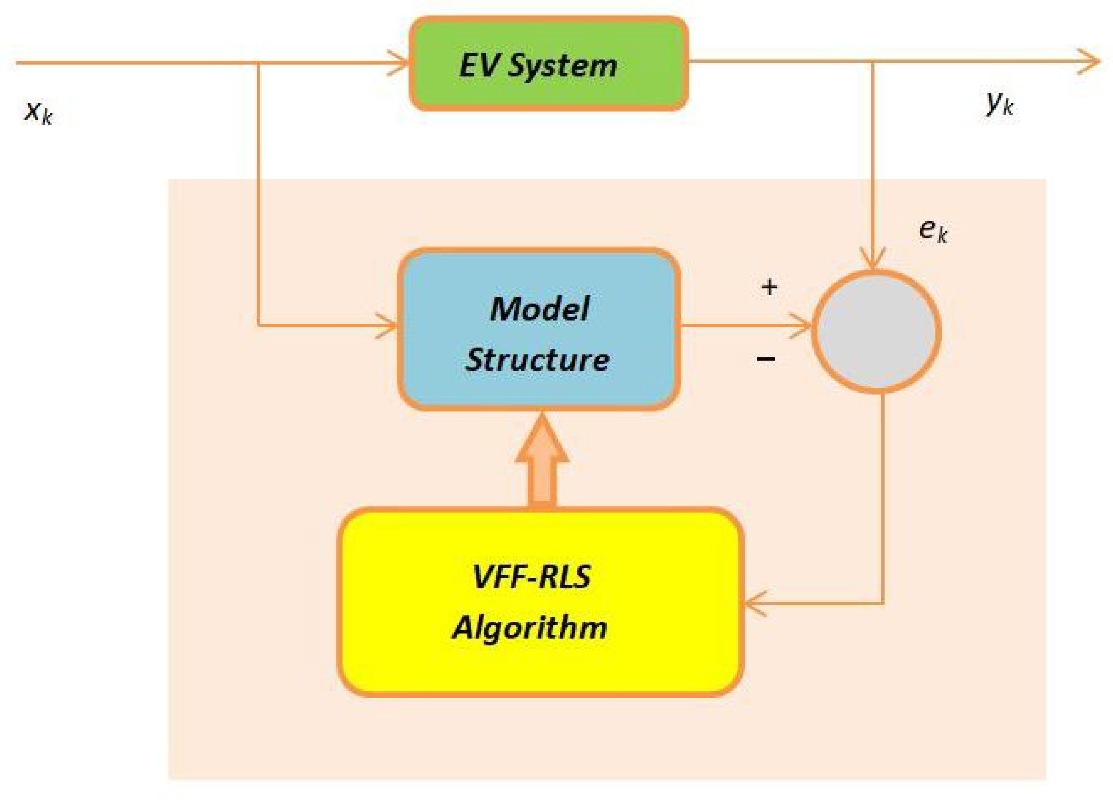
Formulation of the VFF-RLS-Based Algorithm

The VFF-RLS technique outperforms in non-stationary settings with varying statistical characteristics of input signals over time. Because of potential concerns with the step size parameter, the performance of the LMS, RLS, and VFF-RLS algorithms may decrease [36,37,38]. The need for dynamic modification of these variables, in particular, may have a significant influence on the algorithm’s adaption rate. The VFF-RLS approach is usually recognized as more computationally efficient when used for small- to medium-sized problems. The proposed algorithm shows fast convergence and endurance in the face of fluctuating ambient noise, near-end changes in the echo path, and signal variations. The computing cost of the VFF-RLS approach is constant with each iteration, whereas the calculation complexity of the LMS, RLS, and VFF-RLS algorithms grows exponentially with the number of filter taps. In situations with system fluctuations, VFF-RLS may increase the tracking performance. Variable forgetting factor values are used in the standard VFF-RLS technique. When λ approaches one, an algorithm with limited tracking capabilities demonstrates high stability and rapid convergence. Lowering the value of λ increases tracking but reduces the algorithm’s stability and speed of convergence. When the input signals are connected, LMS algorithms take more time to converge to satisfy these competing objectives or require extra phases such as pre-whitening. Optimizing the inverse correlation matrix recursively enhances the VFF-RLS algorithm’s memory efficiency. This allows the memory requirements of the algorithm to remain constant while allowing its parameters to be modified. However, the memory needs are increased by the LMS, RLS, and VFF-RLS algorithms, which mandate keeping track of the input samples for each tap in the filter [39,40,41].
In the fixed forgetting factor RLS method, when the value of the forgetting factor λ approaches 1, the algorithm exhibits rapid convergence but with reduced tracking capabilities. The algorithm’s tracking capabilities can be enhanced by decreasing the value of λ , but this also reduces the speed of convergence. The proposed solution involves the utilization of a VFF-RLS algorithm to address the conflicting demands. The procedure for determining the variable forgetting factor λ ( n ) is outlined in Equations (6)–(10).
For the VFF-RLS algorithm, the parameter E(n) is an initial error that is computed at time ‘m − 1’ [12,42]. The subsequent error is given below:
E ( m ) = E ( m ) [ 1 x T ( m ) G ( m ) ]
The variable forgetting factor λ ( m ) can be modified as
S ( E ( m ) E ( m ) ) = S ( ϵ 2 ( m ) )
And the power of distortion in the system is S ( ϵ 2 ( m ) ) = σ v 2 ( n ) .
S ( E ( m ) E ( m ) ) = S ( E 2 ( m ) ) [ 1 x T ( m ) Q ( m 1 ) x ( m ) λ ( m ) + x T ( m ) Q 1 ( m 1 ) x ( m ) ]
The equation for the variable forgetting factor λ ( m ) can be derived by using Equations (7) and (8) as
λ ( m ) = { w ¯ ( m ) σ v 2 ( m ) | σ E 2 ( m ) σ v 2 ( m ) | } ,
where W ( m ) = x T ( m ) Q 1 ( m 1 ) x ( m ) and S ( E 2 ( m ) ) = σ E 2 ( m ) . The value of w ¯ ( m ) is given as
W ¯ ( m ) = α W ¯ ( m 1 ) ( 1 α ) W ( m )
Here, α is the weighting factor. The VFF-RLS method is slightly more sophisticated than RLS. The variable forgetting factor formula in Equation (9) represents the added complexity of VFF-RLS over RLS. As a result, the VFF-RLS method performs two additional comparisons, 12 multiplications, five additions, one division, and three square roots more than the RLS-based algorithm.
The experimental setup constructed and simulated utilizing FPGA and VHDL coding is implemented for the VFF-RLS-based algorithm. The fundamental block structure of the VFF-RLS-based algorithm for parameter estimation is depicted in Figure 4. Because FPGAs handle data with low latency, they are perfect for applications like control systems, audio processing, and communication systems that need processing performed in real-time or almost real-time. FPGAs can be reprogrammed to employ alternative adaptive filter topologies or to accommodate evolving algorithmic needs. When updating or changing the algorithm, this reconfigurability is useful. When performing specific computations, FPGAs require less energy than their software-based counterparts processing on general-purpose CPUs. This is particularly important in scenarios when power absorption is a crucial factor. The VFF-RLS- and FPGA-based algorithms are executed by Algorithms 1 and 2.
Algorithm 1 VFF-RLS algorithm implementation
  • Provide inputs source, desired, and battery voltage to the system.  
  • Calculate and estimate the insulation resistance and observe the priori error.  
  • iterated for j = 0 to m − 1 samples.  
  • Update the input history vector x(m) using desired output u(m).  
  • Use the last set of filter values to determine the filter output c(m − 1).
    y(m) = x T (m)c(m − 1)  
  • Error computation calculation
    e(m) = u(m) − y(m)  
  • Computation of the gain
    G ( m ) = ( Q 1 ( m 1 ) x ( m ) ) / ( λ + x T ( m ) Q 1 ( m 1 ) x ( m ) )  
  • Update the Q 1 ( m ) matrix for the next iteration
    Q 1 ( m ) = λ 1 [ Q 1 ( m 1 ) G(m) x T ( m ) Q 1 ( m 1 ) ]  
  • For the subsequent iteration, update the filter coefficients
    c(m) = c(m − 1) + G(m)e(m)  
  • Update the value of variable forgetting factor λ ( m )
    λ ( m ) = { w ¯ ( m ) σ v 2 ( m ) | σ e 2 ( m ) σ v 2 ( m ) | }
Algorithm 2 Implementation of FPGA-based VFF-RLS algorithm
process(clk, reset)
variable lambda : real := 0.95; – Default forgetting factor
begin
if reset = ’1’ then
w <= (others => 0.0);
P <= 1.0;
x_reg <= (others => ’0’);
error_reg <= (others => ’0’);
elsif rising_edge(clk) then
Update input signal register
x_reg <= x & x_reg(N-1 downto 1);
Compute the output
a_out <= std_logic_vector(to_slv(w));
Compute the error
error_reg <= std_logic_vector(to_slv((signed(d)- signed(a_out(N-1 downto 0))) * to_fixed(P, 16)));
Update the weight vector and P matrix
if we = ’1’ then
Compute intermediate values
signal P_x : real := 0.0;
for i in 0 to N-1 loop
P_x := P_x + to_fixed(x_reg(i), 8) * w(i);
end loop;
signal alpha : real := 1.0 / ( λ + P_x);
Update weight vector
for i in 0 to N-1 loop
w(i) <= w(i) + alpha * error_reg(i);
end loop;
Update P matrix
P <= lambda * P + alpha * P_x * alpha;
Update the variable forgetting factor
lambda := to_fixed(mu, 8);
end if;
end if;
end process;
function to_slv(data : real) return std_logic_vector is
variable result : std_logic_vector(7 downto 0) := (others => ’0’);
begin
result := std_logic_vector(resize
(real(to_integer(signed(result))
+ data), result’length)); return result;
end function;
function to_fixed(data : real; width : integer) return real is
variable factor : real := 2.0 ** width;
begin
return data * factor;
end function;

3. Results and Discussion

An experimental setup was developed to enable test verification and to validate the effectiveness of the suggested insulation resistance estimation technique. The positive and negative battery connectors have voltage and resistance of 300 V and 2400 K Ω , respectively. The circuit output observed is exported to the a.mat file for analysis in MATLAB using the VFF-RLS approach. There are four specific scenarios which are categorized according to the insulation of the battery terminals in both regular and abnormal situations. Four scenarios are examined against the VFF-RLS algorithm, employing the variable forgetting factor, as follows:
  • Constant resistance and constant voltage (CRCV) condition
  • Variable resistance and constant voltage (VRCV) condition
  • Constant resistance and variable voltage (CRVV) condition
  • Variable resistance and variable voltage (VRVV) condition

3.1. MATLAB-Based Simulation Results

CRCV condition: The system was provided with constant 300 V battery voltage and noise by the Matlab configuration. The system has a 220 K Ω positive insulating resistance and operates at a constant voltage of 300 volts. The AF qualities of this algorithm resulted in significant advancements in the system’s IR and BP performance when compared to the RLS method. The VFF-RLS method improved, and the error was less, as shown in Figure 5. By repeatedly tracking the inverse correlation matrix, the VFF-RLS approach uses less memory overall and can update its parameters. Additionally, the system error has been significantly decreased, with the variable forgetting factor increasing its stability. The system’s error output fell between −3.9 and 4.8.
VRCV condition: Unexpected events, such as short circuits, can cause abrupt variations in the BP’s insulating resistance. The real-time performance of the insulation detecting technique presents more of a difficulty. In this state, the system is exposed to both steady voltage and fluctuating resistance. The resistance undergoes a 20 K Ω shift, beginning at 150 K Ω and focusing primarily at 220 K Ω . This is a continuous change. The aforementioned test results illustrate a type of positive insulating resistance. As depicted in Figure 6, the in-error output signal below fluctuates between −5.9 and 7.5 using the VFF-RLS algorithm. A substantial amount of noise is present in the measured voltage due to sampling precision and system noise. This significantly degrades the computation results of the direct measurement method. More precisely, the amplitude of the feedback signal exhibits a progressive decrease. This happens because increasing insulation resistance causes the split voltage on the R f b to drop—changing the resistance will make the system less stable. Practical ramifications of the insulation resistance on the negative side were also observed. The results of this experiment indicate that the CRCV condition, which was previously utilized, exhibits greater stability than the VRCV condition.
CRVV condition: The battery voltage plus an additional 220 K Ω of resistance are the variables that vary between 290 and 330 volts. The variable voltage and the constant insulating resistance on the positive side are factors considered in this test. The VFF-RLS-based algorithm was employed to evaluate the IR of the system’s battery terminals. The system exhibits reduced stability in the aforementioned situations due to voltage variation. When there is a rapid change in the battery voltage, the algorithm’s computation inaccuracy increases significantly in this instance. As shown in Figure 7, the errors range from −8.03 to 10.13. The voltage fluctuations reduce the stability of the system. In VRCV, analogous empirical findings regarding the adverse aspects of IR. This experimental condition provides evidence that the previously utilized methodology, VRCV, is more suitable than CRVV.
VRVV condition: The resistance of the battery exhibits a progressive variation starting at 150 K Ω , with its primary concentration observed at 220 K Ω . The resistance variation amounts to 20 K Ω . The voltage of the variable battery ranges from 290 V to 330 V. The aforementioned test results are observed when the insulating resistance is unfavorable due to gradual changes in resistance and abrupt changes in voltage, both of which contribute to system instability. As a result of the reduced frequency of voltage and resistance fluctuations, the system’s stability is compromised, leading to the occurrence of errors. The error is extremely high under these conditions, ranging from −15.16 to 13.17, as shown in Figure 8. An identical state of the system is encountered, which is defined by a persistently negative insulating resistance. The battery performance and insulation resistance of the system were assessed using the VFF-RLS method. Compared to the three conditions that preceded it, the system exhibits reduced stability under varying voltage and resistance conditions.

3.2. FPGA-Based Discussion and Results

The four unique criteria of the insulation circuit model were verified using an FPGA-based VFF-RLS method. Xilinx Vivado software was used in conjunction with the VFF-RLS algorithm’s VHDL code to simulate the outcomes. The VFF-RLS algorithm, which takes as inputs the intended voltage, reset, clock, constant voltage and resistance, and the variable resistance, and returns the expected output data, filter weight data, error output, and forgetting factor, is simulated and used in the FPGA module. The FPGA receives input from the system for further processing when the enable signal is high and the reset button is removed. Accurate and consistent output results from the FPGA’s rapid operation. The stability of the system will increase in tandem with the frequency at which the algorithm’s weight is modified. In this experimental configuration, the expedited data sampling results in an increase in the update rate and estimation frequency. Additionally, an enhancement in error estimation was noted. An experimental setup was constructed to evaluate the proposed FPGA-based algorithm under the aforementioned four Matlab test conditions.
The experimental configuration for detecting insulation and electric vehicles is illustrated in Figure 9. The battery kit, motor systems, controller, resistive and motor loadings, and BMS are all introduced in this experiment. The BMS is an electronic device responsible for the management of a system’s rechargeable battery supply. The fundamental operation of a BMS entails the surveillance and regulation of a multitude of battery parameters, including, but not limited to, its charge level, temperature, and voltage. For variations in current and voltage, the electric vehicle system implements a resistive and motor loading. A battery kit, module power (0–300–5 V, 0–5 A), DC resistor, HV power supply module, personal computer (PC), FPGA-based insulation detector, and high-voltage power supply module are the components of the insulation detection test bench. The BP attains the intended voltage for the experiments through the utilization of parallel and series connections between the cells. For the static experiment, a high fixed voltage is supplied by the battery charge. In order to simulate insulation resistance, a resistor is employed. This experiment’s data, which comprise the battery pack voltage, injection signal voltage (Us), feedback signal voltage ( V f b ), and predicted IR value, are stored and evaluated on the personal computer. The laboratory procedures are carried out at ambient temperature. For improved expected results, the FPGA is utilized in place of the MCU to verify the proposed method. The sophisticated FPGA is ideally suited to manage insulation detection failures in electric vehicles.
By using the FPGA-based VFF-RLS method, the results are simulated and tested with an FPGA board and Xilinx Vivado software. The discussion encompasses enhanced FPGA outcomes. The error output of the system in Figure 10, which depicts the CVCR conditions, varies between −1 and +2, indicating an enhancement in performance when compared to the VFF-RLS-based Matlab results. Analogous experimental results have been documented by researchers with respect to the adverse aspects of IR.
The system’s error output, which varies from −3 to +4, was observed in Figure 11 under VRCV conditions, showing an enhancement over the VFF-RLS-based Matlab findings. Comparable tests were carried out to measure the IR on the other side. As opposed to FPGA VRCV, the system maintains stability when voltage and resistance remain constant.
The CRVV conditions are depicted in Figure 12. The system’s error output, which falls within the range of −6 to +7, demonstrates progress in comparison to the simulations conducted in the VFF-RLS based Matlab simulations. Analogous experimental results were obtained in the opposite direction. This experimental condition provides evidence that the method that was previously utilized is more stable in comparison to the FPGA outcomes of CRVV.
Compared to the VFF-RLS-based Matlab results, the error output of the system shown in Figure 13, which depicts the VVVR condition, ranges from −10 to +8. This indicates an improvement in the system with respect to the FPGA-based VFF-RLS algorithm. This experimental situation illustrates the stability and collation capabilities of the previously utilized technique under varying voltage and resistance conditions.

4. Conclusions

The lithium-ion batteries in electric vehicles are part of an HVDC system. Factors such as temperature, humidity, and vibration can significantly impact the insulating resistance of the battery terminal and between the chassis and the DC bus of the BP. This study considers the insulation resistance of EVs’ BPs. The insulation detection principle is explained thoroughly, and the insulation resistance is calculated using the equivalent circuit. This study proposes an adaptive filtering-based system for diagnosing insulation faults of battery back terminals. An architecture for detecting insulation battery packs based on signal injection is specifically created. The battery pack model of positive and negative electrode insulation faults is constructed by equating the electrode insulation fault of the battery pack. VHDL was used to design and build an adaptive VFF-RLS predictor. VFF-RLS was the most successful way to implement AF based on FPGAs. The FPGA-based algorithm was formulated to track signals very accurately, particularly those that fluctuate over a span of time. Because of their register-rich design facility and fast speed, FPGAs are the best option for implementing VFF-RLS. This study developed, simulated, and compared an FPGA-based hardware setup for the detection model using findings from other investigations. Furthermore, the experimental results demonstrated that the suggested approach can promptly detect changes in insulating resistance. The proposed FPGA-based technique produces significantly reduced output errors compared to existing Matlab findings. In future work, we plan to apply the proposed FPGA approach to large vehicles.

Author Contributions

M.B., B.P., R.K., A.M. and N.P. made equal contributions in conceptualization, methodology, software, data curation, formal analysis, writing—review and editing, and writing—original drafts. All authors have read and agreed to the published version of the manuscript.

Funding

This research received no external funding.

Institutional Review Board Statement

Not applicable.

Informed Consent Statement

Not applicable.

Data Availability Statement

The data supporting this study’s findings are available from the corresponding author upon reasonable request. The data are not publicly available due to privacy restrictions.

Acknowledgments

We thank the Manipal Institution Technology Bengaluru for their assistance with laboratory support and use of high-performing computers.

Conflicts of Interest

The authors declare no conflicts of interest.

Abbreviations

The following abbreviations are used in this manuscript:
IR Insulation resistance
FPGA Field-programmable gate array
BP Battery pack
AF Adaptive filtering
DC Direct current
EV Electric vehicle
HVDC High-voltage direct-current
PC Personal computer
RMSE Root mean square error
EKF Extended Kalman filter
VFF RLS Variable forgetting factor recursive least squares
CRCV Constant resistance and constant voltage and condition
LMS Least mean squares
MCU Micro-control unit
BMS Battery management system
VRCV Variable resistance and constant voltage condition
FIR Finite impulse response filter
RLS Recursive least squares
CRVV Constant resistance and variable voltage condition
VRVV Variable resistance and voltage condition
LIB Lithium-ion batteries
VHDL Very-high-speed integrated circuit (VHSIC) hardware description language
BEVs Battery-electric vehicles
Symbols
V b t Terminal voltage of the battery kit
E ( n ) Total squared error
R 1 Values for current-limiting resistances of R l m in mesh-1
R 2 Values for current-limiting resistances of R l m in mesh-2
U s Low-signal source
R f b Feedback resistance
G N D The ground referred to chassis
I 1 Current flowing in loop-1
λ ( n ) Variable forgetting factor
I 2 Current flowing in loop-2
U s Low-signal source
E ( m ) Total squared error
W ( m ) Weight vector signal
x ( m ) Input voltage signal
y ( m ) Output voltage signal
d ( m ) , u ( m ) Reference voltage signal
e 2 ( m ) Root mean square error
C k ( m ) Filter coefficients matrix
G ( m ) Kalman’s gain matrix
Q ( m ) Inverse coefficients matrix
V ( m ) Recursive coefficients matrix
e ( m ) Posteriori error
R ( m ) , r ( m ) Covariance matrices
V ( m ) Recursive coefficients matrix
λ Forgetting factor
μ Step size

References

  1. Aghabali, I.; Bauman, J.; Kollmeyer, P.J.; Wang, Y.; Bilgin, B.; Emadi, A. 800-V Electric Vehicle Powertrains: Review and Analysis of Benefits, Challenges, and Future Trends. IEEE Trans. Transp. Electrif. 2021, 7, 927–948. [Google Scholar] [CrossRef]
  2. Bukya, M.; Sharma, S.; Kumar, R.; Mathur, A.; N, G.; Kumar, P. Electric vehicle grid demand. Potential analysis model and regional architectural planning approach for charging using PVsyst tool. Vis. Sustain. 2024, 21, 8869. [Google Scholar] [CrossRef]
  3. Jung, C. Power Up with 800-V Systems: The benefits of upgrading voltage power for battery-electric passenger vehicles. IEEE Electrif. Mag. 2017, 5, 53–58. [Google Scholar] [CrossRef]
  4. Lian, Y.; Zeng, D.; Ye, S.; Zhao, B.; Wei, H. High-Voltage Safety Improvement Design for Electric Vehicle in Rear Impact. Automot. Innov. 2018, 1, 211–225. [Google Scholar] [CrossRef]
  5. Moghadam, D.E.; Herold, C.; Zbinden, R. Electrical Insulation at 800 V Electric Vehicles. In Proceedings of the 2020 International Symposium on Electrical Insulating Materials (ISEIM), Tokyo, Japan, 13–17 September 2020; pp. 115–119. [Google Scholar]
  6. Bukya, M.; Kumar, R.; Mathur, A. Analytical Computation of Thermal and Electrical Issues in E-Mobility Cabling Network. J. Adv. Res. Fluid Mech. Therm. Sci. 2023, 104, 84–92. [Google Scholar] [CrossRef]
  7. Voltage Classes for Electric Mobility Published by: ZVEI—German Electrical and Electronic Manufacturers’ Association Centre of Excellence Electric Mobility. December 2013. Available online: www.zvei.org (accessed on 8 December 2013).
  8. Bukya, M.; Kumar, R.; Mathur, A. Numerical Investigation on Thermal and Electrical Stress in Electric Vehicle Cabling Network. J. Adv. Res. Fluid Mech. Therm. Sci. 2023, 102, 25–36. [Google Scholar] [CrossRef]
  9. Xu, Y.; Wang, H.; Li, J. Research on Online Insulation Testing of Power Battery of New Energy Vehicles. Int. J. Comput. Appl. Technol. Res. 2021, 10, 1–5. [Google Scholar] [CrossRef]
  10. Rybski, R.; Kaczmarek, J.; Kontorski, K. Impedance Comparison Using Unbalanced Bridge With Digital Sine Wave Voltage Sources. IEEE Trans. Instrum. Meas. 2015, 64, 3380–3386. [Google Scholar] [CrossRef]
  11. Tian, J.; Yin, J. Insulation fault monitoring of lithium-ion battery pack: Recursive least square with adaptive forgetting factor. J. Energy Storage 2023, 67, 107624. [Google Scholar] [CrossRef]
  12. Bukya, M.; Malthesh, S.; Kumar, R.; Mathur, A. Insulation Detection of Electric Vehicles by Using FPGA-Based Recursive-Least-Squares Algorithm. World Electr. Veh. J. 2024, 15, 25. [Google Scholar] [CrossRef]
  13. Chen, Z.; Cui, W.; Cui, X.; Qiao, H.; Lu, H.; Qiu, N. A New Method of Insulation Detection on Electric Vehicles Based on a Variable Forgetting Factor Recursive Least Squares Algorithm. IEEE Access 2021, 9, 73590–73607. [Google Scholar] [CrossRef]
  14. Tian, J.; Wang, Y.; Yang, D.; Zhang, X.; Chen, Z. A real-time insulation detection method for battery packs used in electric vehicles. J. Power Sources 2018, 385, 1–9. [Google Scholar] [CrossRef]
  15. Bukya, M.; Kumar, R.; Mathur, A. Electrical Vehicles Insulation Detection Using Virtex 7 FPGA. In Innovations in Computational Intelligence and Computer Vision; ICICV 2022; Lecture Notes in Networks and Systems; Springer: Singapore, 2023; Volume 680. [Google Scholar] [CrossRef]
  16. Ma, S.; Jiang, M.; Tao, P.; Song, C.; Wu, J.; Wang, J.; Deng, T.; Shang, W. Temperature effect and thermal impact in lithium-ion batteries: A review. Prog. Nat. Sci. Mater. Int. 2018, 28, 653–666. [Google Scholar] [CrossRef]
  17. Xuezhe, W.; Lu, B.; Zechang, S. A Method of Insulation Failure Detection on Electric Vehicle Based on FPGA. In Proceedings of the IEEE Vehicle Power and Propulsion Conference (VPPC), Harbin, China, 3–5 September 2008. [Google Scholar]
  18. Wen, F.; Pei, W.; Li, Q.; Chu, Z.; Zhao, W.; Wu, S.; Zhang, X.; Han, C. Insulation Monitoring of Dynamic Wireless Charging Network Based on BP Neural Network. World Electr. Veh. J. 2021, 12, 129. [Google Scholar] [CrossRef]
  19. Shen, Y.; Liu, A.; Cui, G.; Ge, G. Yongpeng Shen, Design of Online Detection System for Insulation Resistance of Electric Vehicle Based on Unbalanced Bridge. In Proceedings of the 2019 IEEE PES Innovative Smart Grid Technologies Asia, Chengdu, China, 21–24 May 2019. [Google Scholar]
  20. Zhao, C.; Li, Q. Research on On-line Monitoring Methods of High Voltage Parameter in Electric Vehicles. World Electr. Veh. J. 2010, 4, 232–237. [Google Scholar] [CrossRef]
  21. Li, J.; Wu, Z.; Fan, Y.; Wang, Y.; Jiang, J. Research on Insulation Resistance On-Line Monitoring for Electric Vehicle. In Proceedings of the 2005 International Conference on Electrical Machines and Systems, Nanjing, China, 27–29 September 2005. [Google Scholar]
  22. Bi, L.; Wei, X.; Sun, Z. A High-voltage Safety Protection Method for Electric Vehicle Based on FPGA. In Proceedings of the 2006 IEEE International Conference on Vehicular Electronics and Safety, Harbin, China, 13–15 September 2006. [Google Scholar]
  23. Wu, Z.-J.; Wang, L.-F. A novel insulation resistance monitoring device for Hybrid Electric Vehicle. In Proceedings of the 2008 IEEE Vehicle Power and Propulsion Conference, Harbin, China, 3–5 September 2008; pp. 1–4. [Google Scholar] [CrossRef]
  24. Dai, Q.; Zhu, Z.; Huang, D.; Du, M.; Wei, K. Insulation Detection of Electric Vehicle Batteries. AIP Conf. Proc. 2018, 1971, 040021. [Google Scholar]
  25. Wang, Y.; Tian, J.; Chen, Z.; Liu, X. Model based insulation fault diagnosis for lithium-ion battery pack in electric vehicles. Measurement 2019, 131, 443–451. [Google Scholar] [CrossRef]
  26. Xin, Z.; Shouping, C. Study on insulation detection method of electric vehicles based on single point of failure model. In Proceedings of the 2016 11th International Forum on Strategic Technology (IFOST), Novosibirsk, Russia, 1–3 June 2016; pp. 191–194. [Google Scholar] [CrossRef]
  27. Chiang, Y.-H.; Sean, W.-Y. Adaptive Control for Estimating Insulation Resistance of High-Voltage Battery System in Electric Vehicles. In New Trends in Electrical Vehicle Powertrains; IntechOpen: London, UK, 2019. [Google Scholar] [CrossRef]
  28. Pei, X.; Hu, X.; Liu, W.; Chen, Z.; Yang, B. State Estimation of Vehicle’s Dynamic Stability Based on the Nonlinear Kalman Filter. Automot. Innov. 2018, 1, 281–289. [Google Scholar] [CrossRef]
  29. Pande, A.S.; Soni, B.P.; Bhadane, K.V. Electrical Models for EV’s Batteries: An Overview and Mathematical Design of RC Network. J. Inst. Eng. India Ser. B 2023, 104, 533–547. [Google Scholar] [CrossRef]
  30. Oh, H.; Jeon, J.; Park, S. Effects of Battery Model on the Accuracy of Battery SOC Estimation Using Extended Kalman Filter under Practical Vehicle Conditions Including Parasitic Current Leakage and Diffusion Of Voltage. Int. J. Automot. Technol. 2021, 22, 1337–1346. [Google Scholar] [CrossRef]
  31. Cai, W.; Wu, X.; Zhou, M.; Liang, Y.; Wang, Y. Review and Development of Electric Motor Systems and Electric Powertrains for New Energy Vehicles. Automot. Innov. 2021, 4, 3–22. [Google Scholar] [CrossRef]
  32. Hu, J.; Wei, Z.; He, H. An Online Adaptive Internal Short Circuit Detection Method of Lithium-Ion Battery. Automot. Innov. 2021, 4, 93–102. [Google Scholar] [CrossRef]
  33. Yi, H.; Yang, S.; Zhou, S.; Zhou, X.; Yan, X.; Liu, X. An Innovative State-of-charge Estimation Method of Lithium-ion Battery Based on 5th-order Cubature Kalman Filter. Automot. Innov. 2021, 4, 448–458. [Google Scholar] [CrossRef]
  34. Zhang, L.; Ning, L.; Yang, X.; Zeng, S.; Yuan, T.; Li, G.; Ke, C.; Zhang, J. Half-Power Prediction and Its Application on the Energy Management Strategy for Fuel Cell City Bus. Automot. Innov. 2023, 6, 131–142. [Google Scholar] [CrossRef]
  35. Mekhfioui, M.; Elgouri, R.; Satif, A.; Moumouh, M.; Hlou, L. Implementation of Least Mean Square Algorithm Using Arduino & Simulink. Int. J. Sci. Technol. Res. 2020, 9, 664–667. [Google Scholar]
  36. Salah, M.; Zekry, A.-H.; Kamel, M. FPGA implementation of LMS adaptive filter. In Proceedings of the 2011 28th National Radio Science Conference (NRSC), Cairo, Egypt, 26–28 April 2011; pp. 1–8. [Google Scholar] [CrossRef]
  37. Godbole, S.S.; Palsodkar, P.M.; Raut, V.P. FPGA Implementation of Adaptive LMS Filter. Proc. Spit IEEE Colloq. Int. Conf. 2011, 2, 226–229. [Google Scholar]
  38. Zhang, X.; Yang, S.; Liu, Y.; Zhao, W. Improved Variable Step Size Least Mean Square Algorithm for Pipeline Noise. Sci. Program. 2022, 2022, 3294674. [Google Scholar] [CrossRef]
  39. Peters, S.D.; Antoniou, A. A parallel adaptation algorithm for recursive-least-squares adaptive filters in nonstationary environments. IEEE Trans. Signal Process. 1995, 43, 2484–2495. [Google Scholar] [CrossRef]
  40. Moon, T.K.; Stirling, W.C. Mathematical Methods and Algorithms for Signal Processing; Prentice Hall: Upper Saddle River, NJ, USA, 2000. [Google Scholar]
  41. Diniz, P.S.R. The Least-Mean-Square (LMS) Algorithm. In Adaptive Filtering. The Springer International Series in Engineering and Computer Science; Springer: Boston, MA, USA, 1997; Volume 399. [Google Scholar] [CrossRef]
  42. Zhuang, W. RLS Algorithm with Variable Fogetting Factor for Decision Feedback Equalizer over Time-Variant Fading Channels. Wirel. Pers. Commun. 1998, 8, 15–29. [Google Scholar] [CrossRef]
Figure 1. Electric vehicle insulation failure causes.
Wevj 15 00129 g001
Figure 2. Different insulation detection methods in EV.
Wevj 15 00129 g002
Figure 3. (a) Battery insulation fault detection model. (b) Insulation fault simplified circuit model at positive side. (c) Insulation fault simplified circuit model at negative side.
Wevj 15 00129 g003
Figure 4. Block diagram for VFF-RLS-based parameter estimation.
Wevj 15 00129 g004
Figure 5. IR error in both CV and CR scenarios.
Wevj 15 00129 g005
Figure 6. Error in IR in CV and VR scenarios.
Wevj 15 00129 g006
Figure 7. Error in insulation resistance in VV and CR scenarios.
Wevj 15 00129 g007
Figure 8. Insulation resistance inaccuracy in VR and VV scenarios.
Wevj 15 00129 g008
Figure 9. Electric vehicle experimental configuration and insulation detection test.
Wevj 15 00129 g009
Figure 10. Simulation of FPGA hardware under CRCV condition.
Wevj 15 00129 g010
Figure 11. Simulation of FPGA hardware in CV and VR scenarios.
Wevj 15 00129 g011
Figure 12. Simulation of FPGA hardware under VV and CR situations.
Wevj 15 00129 g012
Figure 13. Simulation of FPGA hardware in VVVR scenarios.
Wevj 15 00129 g013
Disclaimer/Publisher’s Note: The statements, opinions and data contained in all publications are solely those of the individual author(s) and contributor(s) and not of MDPI and/or the editor(s). MDPI and/or the editor(s) disclaim responsibility for any injury to people or property resulting from any ideas, methods, instructions or products referred to in the content.

