Article

Research on Collaborative Control of Differential Drive Assisted Steering and Active Front Steering for Distributed Drive Electric Vehicles

1
College of Vehicle and Traffic Engineering, Henan University of Science and Technology, Luoyang 471003, China
2
Ningbo Shenglong Group Co., Ltd., Ningbo 315104, China
*
Author to whom correspondence should be addressed.
World Electr. Veh. J. 2023, 14(10), 292; https://doi.org/10.3390/wevj14100292
Submission received: 14 August 2023 / Revised: 28 August 2023 / Accepted: 28 September 2023 / Published: 13 October 2023

Abstract

:
A collaborative control strategy for distributed drive electric vehicles (DDEVs) focusing on differential drive assisted steering (DDAS) and active front steering (AFS) is proposed to address the issues of sudden torque changes, reduced steering characteristics, and weak collaborative control capabilities caused by the coupling of the AFS and DDAS systems in DDEVs. This paper establishes a coupled dynamic model of the AFS and DDAS systems and, on this basis, designs AFS controllers for yaw velocity feedback control and DDAS controllers for steering wheel torque control, respectively. Additionally, it analyzes the interference factors of the two control systems and develops a collaborative control strategy for DDAS and AFS; this control strategy establishes a corner motor correction module, steering wheel torque correction module, and assistance correction module. Co-simulation is carried out on Matlab/Simulink and the Carsim platform to verify the correctness of the model under typical working conditions; to reduce the sudden change in the steering wheel torque caused by AFS additional angle interventions; to improve the poor steering characteristics caused by DDAS, introducing additional yaw torque; to greatly enhance the collaborative control effect; and to meet the requirements for vehicle handling stability, portability, and safety.

1. Introduction

DDEVs have the characteristics of a compact structure, efficient transmission, and the independent and controllable driving and braking torque of each wheel. Therefore, DDAS [1] can be achieved by controlling the driving force of each steering wheel to generate a difference in the driving torque, which offsets the steering resistance torque. As a new type of power assist system, DDAS can meet the requirements of vehicle steering, including being lightweight and having steering “road sense” [2,3]; it can improve the active safety of the vehicle. Meanwhile, the commonly used AFS system in vehicles can enhance the operational stability and safety of the steering system by actively applying additional angles to change the angular displacement transmission characteristics [4]. At present, independent chassis control systems using DDAS or AFS alone are far from meeting consumers’ requirements for vehicle driving performance. Chassis-integrated control technology has become a research focus in recent years due to the advantages of eliminating conflicts between various systems and improving vehicle performance [5,6]. Therefore, a DDAS system that integrates the active steering function represents an important development direction for electric vehicle steering systems.
With respect to the research on DDAS systems, Wang, J. [7] proposed a hierarchical coordinated control method for DDAS and vehicle stability control, which effectively improved the handling stability of DDAS under harsh driving conditions. Zhong, Z.H. et al. [8] proposed a steering wheel torque direct control strategy based on the reference steering wheel torque and designed a DDAS controller based on hub-motor-driven vehicles, which improved handling stability and reduced the driver’s handling burden. Yu, Z.P. [9] proposed a DDAS closed-loop control strategy based on the reference steering wheel torque as the control objective, improving the vehicle’s steering portability. Lu, S.F. [10] proposed a coordinated control method for electronic differential and DDAS. By distributing the torque of the left and right wheel hub motors and setting weight coefficients, a coordinated control strategy was designed to improve the handling stability and steering portability of distributed drive electric vehicles. Wang, J.N. [11] introduced an active disturbance rejection control method into the control issue of DDAS. This method can not only obviously reduce the steering wheel effort of the driver but also has a better non-linear control performance with respect to the tracking accuracy and smooth road feeling of the driver. Cheng, X.L. [12] proposed a coordinated control method considering lateral stability and DDAS performance which improved the lateral stability and handling performance of in-wheel motor drive electric vehicles. Although these studies have played an important role in improving vehicle safety and handling stability, they have not considered the active control effect of AFS on DDAS. In fact, the AFS system uses the displacement transmission characteristics of the angle motor and a double-row planetary gear train (PGT). Through variable steering ratio control and active steering intervention stability control [13], the contradiction between low-speed steering portability and high-speed steering stability is better solved so that the driver’s “sense of road” and the vehicle’s handling stability are coordinated [14,15,16]. Gao, X.J. et al. [17] analyzed in detail the structure and working principle of BMW’s AFS system as well as the control principle of the variable transmission ratio and vehicle stability control. Sang, N. [18] proposed a method for AFS control for vehicles based on an extended state observer and non-singular terminal sliding mode, which effectively improved vehicles’ handling stability. Li, S.S. [19] proposed an improved linear time-varying model predictive control method based on a non-linear tire model. This method can expand the stability range of AFS vehicles and improve the stability of AFS vehicles under extreme operating conditions. Zhang, N.N. [20] proposed a multi-objective optimization coordinated control method for the anti-lock braking system and AFS based on multi-agent model predictive control. It improves the safety and stability of DDEVs when braking on low-adhesion roads or off-roads. Therefore, integrating AFS for active control can achieve higher security and the coordinated control of DDAS systems. However, after integrating into the AFS system, the DDAS system achieves assistance by changing the driving torque of the wheels on both sides of the front axle. At the same time, a yaw couple moment is introduced to affect the yaw velocity gain of AFS for a variable transmission ratio, thus changing the dynamic characteristics of the steering system.
Many scholars have also explored and studied this. Wang, C.Y. [21] designed an ideal steering ratio for an AFS system with a fixed yaw velocity gain and proposed an additional angle closed-loop control strategy for AFS based on this law. Zheng, H.Y. [22] used the fuzzy PID control algorithm to study the variable steering ratio of the AFS system and proved that the designed variable steering ratio law can effectively improve the “low-speed steering flexibility” and “high-speed steering stability” of vehicles. Shang, G.G. [23] analyzed the working principle of the double-row PGT of the AFS system, reasonably selected the yaw velocity gain within the ideal range, and verified the effectiveness of the designed variable transmission ratio of the AFS system. To fit the variable transmission ratio curve, Zhou, B. [24] designed an adaptive and improved variable transmission ratio curve by using the fuzzy reasoning method, expanded the variable transmission ratio function to the level of stability control, and improved the stability and safety of vehicles when driving on low-adhesion roads. Wang, C. [25] found, in the design process of the steering ratio, that maintaining a steady-state vehicle system gain as the vehicle speed increases is beneficial for improving the driver’s driving experience while maintaining vehicle stability. At the same time, an active steering intervention by the AFS system can easily lead to sudden changes in steering wheel torque [26,27,28,29], disrupting the good road feel of the original DDAS system, causing driver discomfort and interference, thereby affecting the stability of the steering system and not conducive to driving safety [30]. Wang, J.N [31] developed a differential collaborative active steering control strategy for an electric wheel front axle independent drive vehicle to reduce the sudden change in steering wheel torque. Wang, J.N. [32] proposed a differential cooperative active steering system control method for electric wheel front axle independent drive vehicles, and it can effectively weaken the sudden torque change of the steering wheel controlled by the DDAS system when the AFS system intervenes and ensure that the driver has a good road sense. At present, the effectiveness of these studies in suppressing sudden changes in steering wheel torque is not ideal, and further research is still needed.
Therefore, this paper proposes a control strategy for the collaborative control of DDAS and AFS in DDEV. Based on establishing a coupled dynamic model of the AFS system and DDAS system, a driver model is established, and control strategies for the two subsystems are developed separately, based on analyzing the factors that interfere with each other between the two subsystems, developing DDAS and AFS collaborative control strategies. The co-simulation is carried out on Matlab/Simulink and Carsim platforms to verify the correctness of the model under typical working conditions and improve the vehicle’s handling stability and steering portability.
The remainder of this article is organized as follows.
In Section 2, the system structure and model are established. In Section 3, the Control Strategy of the AFS System for Yaw Velocity Feedback is based. Section 4 establishes the DDAS System Control Strategy for steering wheel torque. In Section 5, the AFS Integrates DDAS Collaborative Control Strategy is set. In Section 6, the simulation experiment results are discussed. In Section 7, the conclusion is provided.

2. System Structure and Model

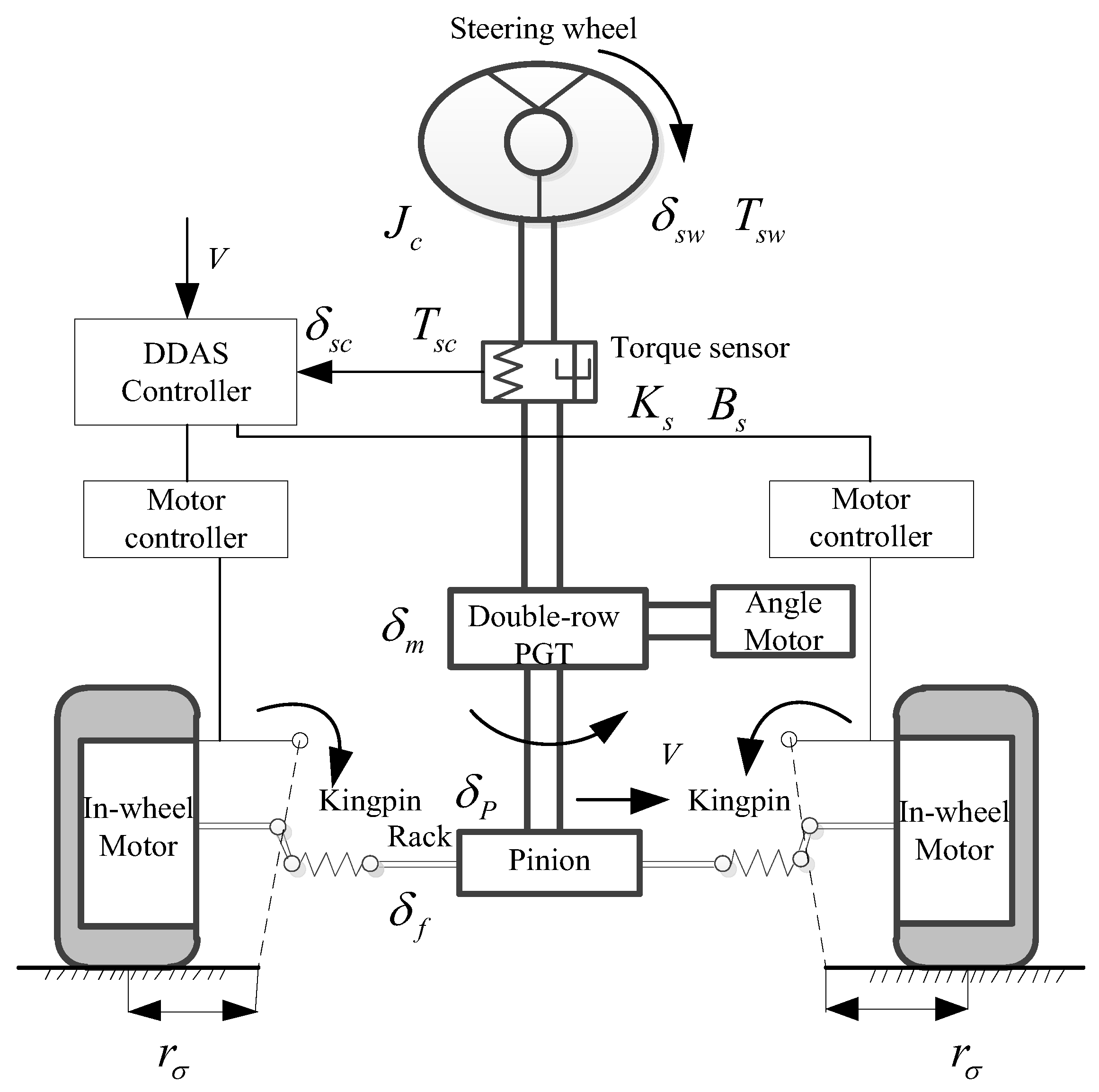
2.1. System Structure and Implementation Principle

The structure of the DDAS integrated with the AFS is shown in Figure 1, in which the system adds one angle motor and one double-row PGT to the DDAS system. According to the functions achieved by the active steering actuator motor, the active steering actuator motor is abbreviated as an angled motor. The double-row PGT [33] is shown in Figure 2.

2.2. System Dynamics Model

The steering wheel and column models are:
J c δ ¨ s w + B c δ ˙ s w + K c ( δ s w δ c ) = T s w
T c = K c ( δ s w δ c )
where Jc and Bc are the equivalent inertia and damping coefficients of the steering wheel and column; δsw and Tsw, respectively, refer to the steering wheel angle and torque; Kc is the torsional stiffness of the steering column; and δc and Tc are the input angle and torque for the upper row star gears.
In the active steering system, the front wheel angle is jointly controlled by driver input and motor input [34]. The additional steering angle δm applied by active steering is linearly superimposed with the steering wheel angle δc through a double-row PGT, and the superimposed steering shaft angle is δs
δ s = 1 i s δ c + 1 i m G h δ m
Y R = r p δ c
where is is the transmission ratio between the sun gears of two planetary gear systems (1 in the text); im is the transmission ratio from the planetary gear to the output wheel; Gh is the worm gear reduction ratio from the motor to the gear ring reduction mechanism; δc is the angle of rotation applied by the driver to the steering column; and δs is the superimposed steering angle obtained on the steering column. YR is the displacement of the gear rack. rp is the radius of the pinion.
According to the principle of torque balance, the motor Equations of motion can be established:
J m δ ¨ m + B m δ ˙ m + K m ( δ m Y R / r p i m ) = T m
T m = K t i 0
where Jm is the moment of inertia of the motor shaft, δm is the additional angle, Bm is the damping coefficient of the steering shaft, and Km is the rigidity coefficient of the motor output shaft; YR is Rack displacement, im is the transmission ratio of the electric motor reduction mechanism; Tm is the motor torque, Kt is the motor torque coefficient; i0 is the target current of the motor;
Rack and pinion translational model:
M R Y ¨ R + B R Y ˙ R + η B ( T K L 1 N L 1 + T K L 2 N L 2 ) = η F T c r p
Rotation motion model of the left turn wheel around its kingpin:
J F W 1 δ ¨ F W 1 + B F W 1 δ ˙ F W 1 + C F F W 1 + A T S 1 = T K L 1
Rotation motion model of the right steering wheel around its kingpin:
J F W 2 δ ¨ F W 2 + B F W 2 δ ˙ F W 2 + C F F W 2 + A T S 2 = T K L 2
T kp 1 = K k p 1 ( Y R N l 1 δ F W 1 )
T kp 2 = K k p 2 ( Y R N l 2 δ F W 2 )
ηF and ηB, respectively, represent the forward and reverse transmission efficiency of the steering gear; MR and BR, respectively, are the mass and damping of the steering gear rack, TKL1 and TKL2 are the torque transmitted by the left and right steering wheel kingpins; Kkp1 and Kkp2, respectively, are the torsional stiffness of the left and right steering wheel kingpins, NL1 and NL2, respectively, refer to the transmission ratios of the left and right steering wheels of the steering gear; JFW1 and JFW2 are, respectively, the moment of inertia of the left and right steering wheels around their kingpins; BFW1 and BFW2 are the viscous damping of the left and right steering wheel kingpins. δFW1 and δFW2 refer to the left and right steering wheel angles; CFFW1 and CFFW2 are, respectively, the dry friction torque of the left and right steering wheels around the kingpin; ATS1 and ATS2 are the return torque of the left and right steering wheels around the kingpin.

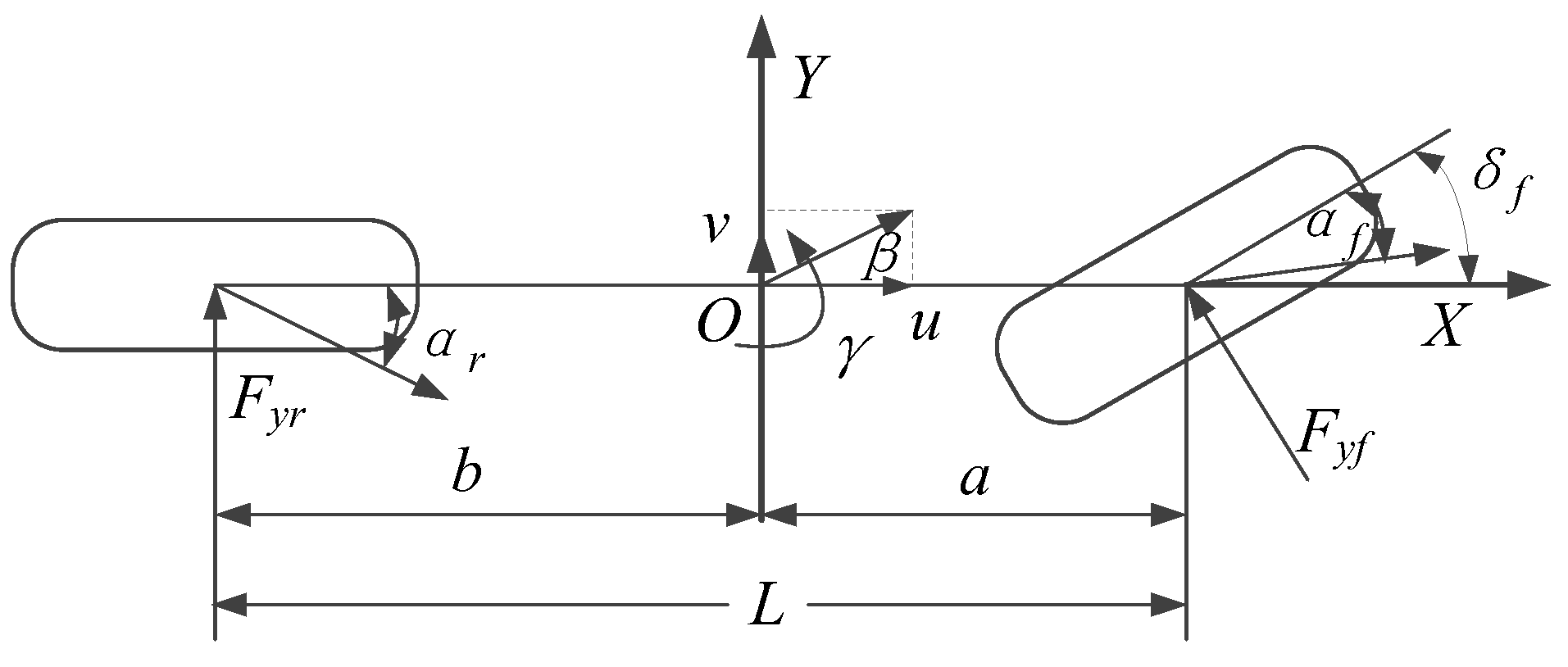
2.3. Two Freedom Vehicle Reference Model
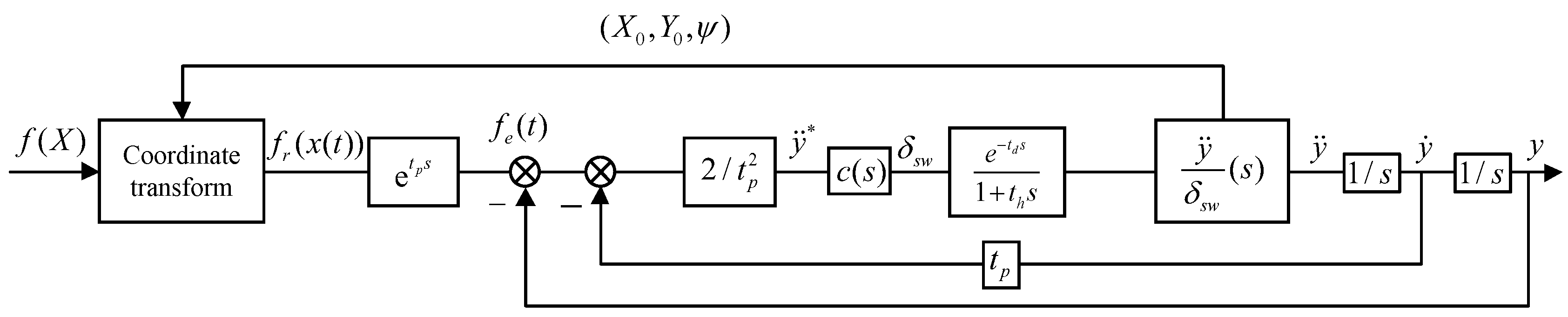
Establish a two-degree-of-freedom vehicle reference model for lateral and yaw motion, and establish a two-degree-of-freedom vehicle model, as shown in Figure 3.
The differential equation of vehicle motion with two degrees of freedom can be expressed as:
{ ( k 1 + k 2 ) β + 1 u ( a k 1 b k 2 ) ω r k 1 δ f = m ( v ˙ + u ω r ) ( a k 1 b k 2 ) β + 1 u ( a 2 k 1 b 2 k 2 ) ω r a k 1 δ f = I z ω ˙ r
where Iz is the moment of inertia of the car rotating around the z-axis; m is the mass of the entire vehicle; k1 is the front wheel lateral stiffness; k2 is the rear wheel lateral stiffness; ωr is the yaw velocity of the vehicle during steering; δf is the front wheel angle of the car; a, b is the distance from the front and rear axles to the center of mass of the vehicle; u is the speed of the car along the x-axis direction, which is the forward speed of the vehicle. v is the lateral speed of the car.

2.4. Driver Model

A closed-loop single-point preview PID driver model based on vehicle lateral acceleration input has been established [35], as shown in Figure 4. This model has high calculation accuracy, simple parameter adjustment, and avoids the complex calculation of vehicle characteristic parameters.

3. AFS System Control Strategy Based on Yaw Velocity Feedback

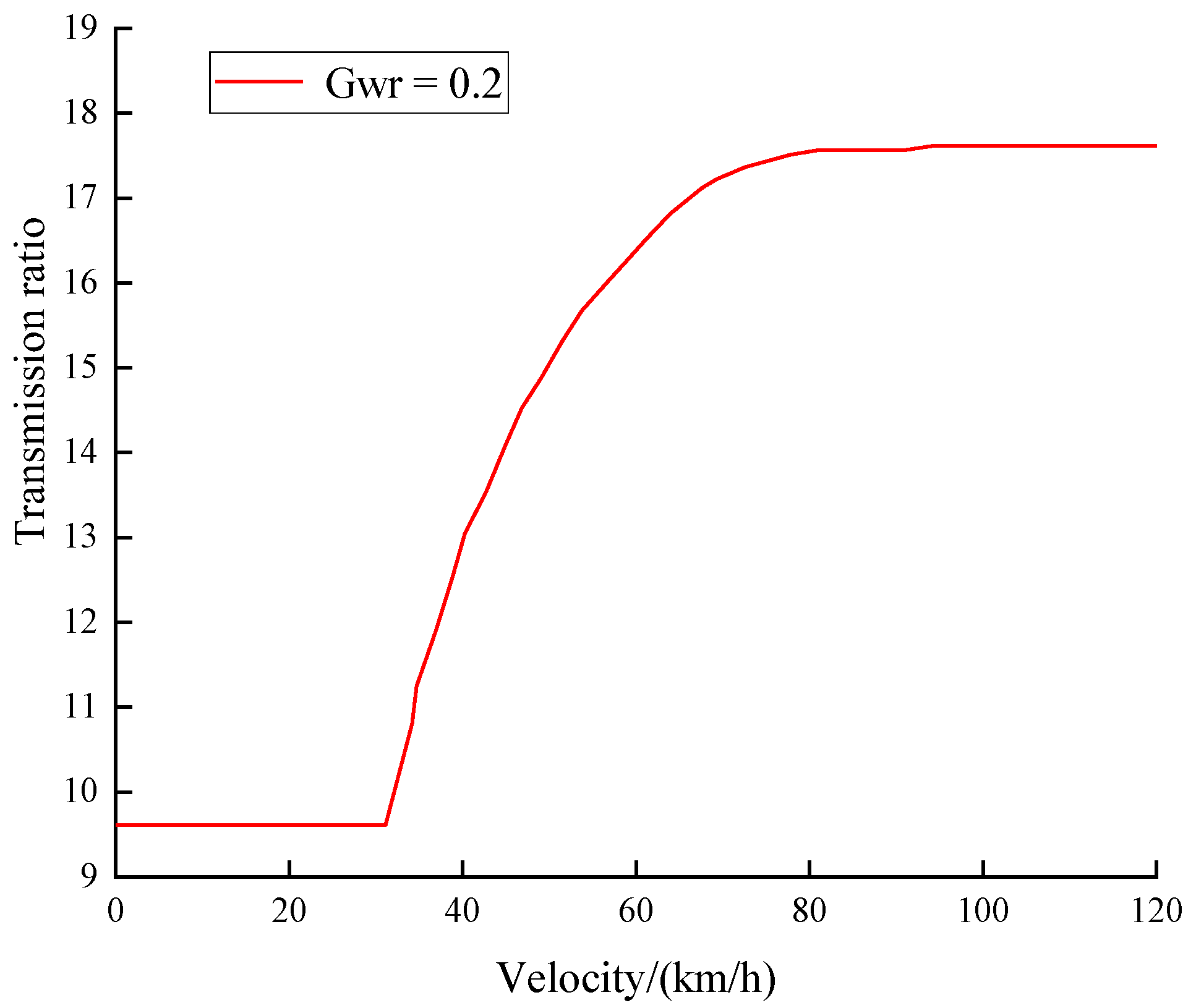
3.1. Design of Variable Transmission Ratio Curve

When the vehicle’s yaw velocity gain or lateral acceleration gain is a fixed value, the steering characteristics of the car are stable [36]. Therefore, during vehicle operation, it is necessary to integrate the control laws of steady-state yaw velocity gain and steady-state lateral acceleration gain to design an ideal variable transmission ratio curve [37,38] due to different vehicle speeds having other requirements for the angular displacement ratio of the steering system. The speed (u ∈ [0,120]) is divided into low-speed, medium-speed, and high-speed zones according to the research needs. In the low-speed zone (u ∈ [0,20]), the fixed transmission ratio is adopted to realize the light steering at low speed. In the high-speed zone (u ∈ [70,120]), the driver adjusts the vehicle’s driving state by slightly turning the steering wheel when the car is driving in a straight line at high speed. However, even minor steering wheel disturbances can cause a large yaw velocity of the vehicle. Therefore, setting the transmission ratio higher makes the steering system sluggish, achieving the stability of the vehicle’s handling.
The ideal transmission ratio law using a combination of fixed yaw velocity gain and set lateral acceleration gain:
i = { 9.6 ( u [ 0 , 20 ] ) u u L 1 + m L 2 ( a k 2 b k 1 ) u 2 1 G a y ( u [ 20 , 70 ] ) C w r u u L 1 + m L 2 ( a k 2 b k 1 ) u 2 1 G a y + C a y u u L 1 + m L 2 ( a k 2 b k 1 ) u 2 1 G a y ( u [ 70 , 120 ] )
Cwr and Cay are the weight coefficients in the equation, and Cwr + Cay = 1. Gay is the fixed lateral acceleration gain. Gwr is the yaw rate gain. By setting two weight coefficients, the variable transmission ratio adjusts the smooth transition, making the variable transmission ratio curve silky and smooth. To achieve slight changes in the transmission ratio in the high-speed zone, Cwr = 0.2 and Cay = 0.8 are taken. The transmission ratio curve is shown in Figure 5. According to the variation characteristics of the variable transmission ratio in Figure 5, it can be seen that by adjusting the size of the fixed yaw velocity gain. When the final yaw velocity gain is determined to be Cwr = 0.2, the transmission ratio changes most smoothly in the high-speed range, and at a speed limit of u = 70 km/h, the variation of the transmission ratio curve is the smoothest, meeting the design requirements of the variable transmission ratio curve.

3.2. AFS Control Strategy

For the AFS system, by controlling the steering of the AFS executing motor, the angle of the steering shaft can be increased or decreased; that is, a positive or negative auxiliary angle can be input based on the angle input by the driver to change the angle of the front wheel. The basic principle is shown in Figure 6.

4. DDAS System Control Strategy Based on Steering Wheel Torque

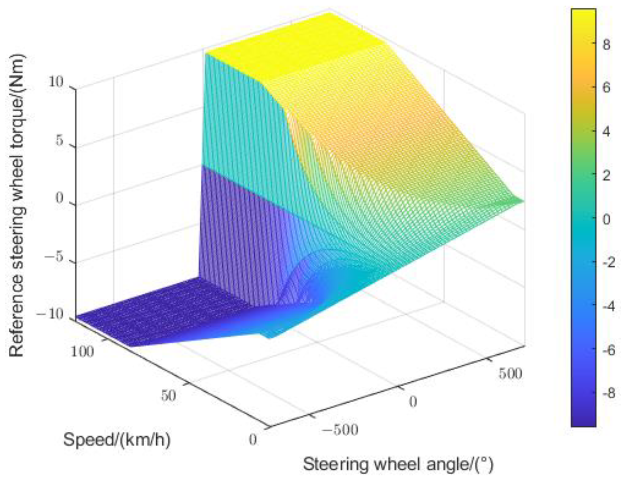
4.1. Assistance Characteristic Curve

While driving the vehicle, the driver corrects the vehicle assistance through the road sense feedback information to ensure the efficient and safe operation of the car. However, reducing steering wheel torque through aid will result in blurred road sense information. Therefore, establish an ideal MAP of reference steering wheel torque, vehicle speed, and steering wheel angle to determine the ideal steering wheel torque [1], as shown in Figure 7.

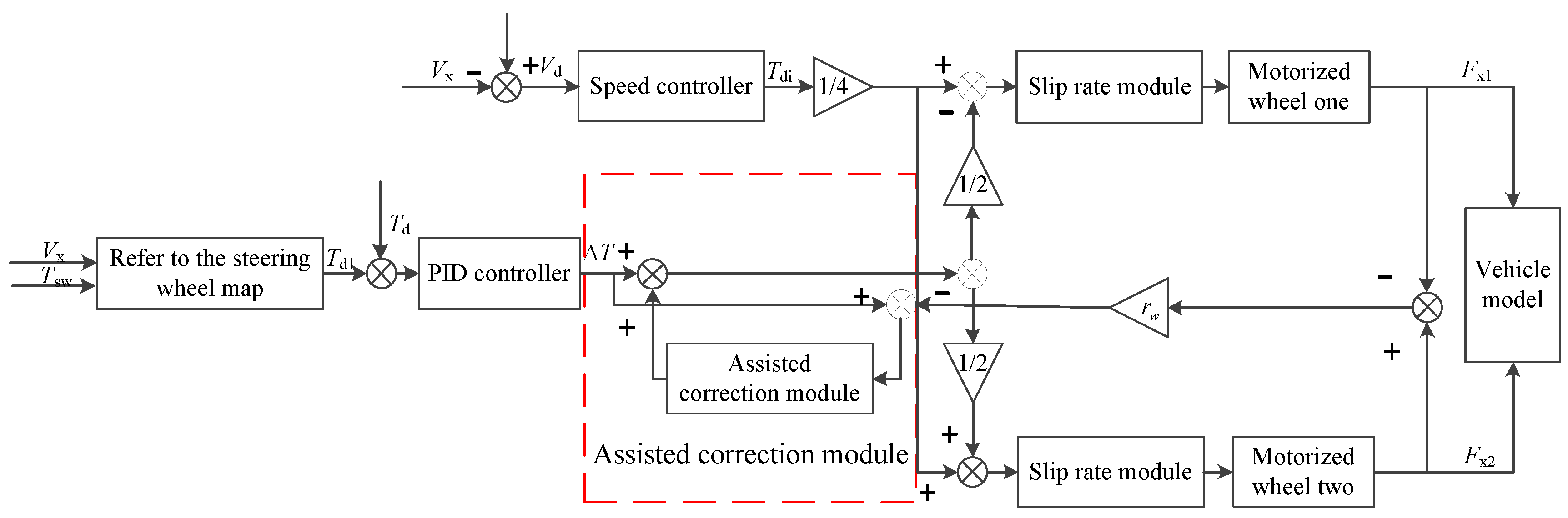
4.2. DDAS Direct Control Strategy

Based on the DDAS principle and DDAS assisting characteristic curve, this paper designs a steering wheel torque direct control strategy. This strategy utilizes the torque difference between the left and right front wheels to generate assistance and apply it to the steering system. It controls the deviation between the actual steering wheel torque Td and the reference steering wheel torque Tdi. The assistance correction module has been developed to adjust the driving torque difference in real time to eliminate the adverse effects of tire nonlinearity and other factors on the power assist system. This ensures that the DDAS system produces the expected power assist characteristics. The schematic diagram is shown in Figure 8.

5. AFS Integrates DDAS Collaborative Control Strategy

5.1. Analysis of the Interaction Mechanism between Two Systems

5.1.1. DDAS Impact on AFS Performance

The DDAS system changes the torque difference between the drive wheels on both sides of the front axle to achieve DDAS. However, an additional yaw moment is introduced at the same time, which affects the yaw motion of the vehicle:
M zd = ( F x 2 F x 1 ) B
I z ω r = F y 1 a F y 2 b + M zd
where Fx1 and Fx2 are the longitudinal forces exerted by the left and right wheels of the front axle on the vehicle along the vehicle coordinate system; B is the tread; Iz is the moment of inertia of vehicle yaw motion; ωr is the vehicle’s yaw velocity, Fy1 and Fy2 are the sum of the lateral forces exerted on the car by the front and rear axles along the vehicle coordinate system, respectively, a and b, the distance from the center of mass to the center of the front and rear axles.
The steady-state yaw velocity gain of the vehicle can be expressed as:
G w r = ω r δ s w = U / L 1 + K U 2 1 i
where K is the stability factor, and i is the total transmission ratio of the steering system. As can be seen from the equation, the introduction changes the magnitude of the value, which is determined by the ideal steering wheel angle transmission ratio based on AFS, thereby affecting the dynamic characteristics of the steering system.

5.1.2. The Impact of AFS on DDAS

The effect of the AFS system is that the additional Angle applied by the active steering intervention changes the angular output of the steering pinion and then changes the angular displacement ratio of the total steering system. Active steering intervention can cause changes in the return torque, leading to sudden changes in the steering wheel torque.
When additional angle intervention is applied to active steering, the steering gear pinion angle is:
δ s = 1 i s δ c + δ m G afs
make
i m G h = G a f s
Gafs is the equivalent reduction ratio of the transmission ratio from the planetary gear to the output wheel and the worm gear reduction ratio from the motor to the ring gear reduction mechanism.
Combined with the two-degree-of-freedom vehicle model, the transfer function from the steering pinion angle to the steering resistance moment [30] is derived as follows:
T R ( s ) = P ( s ) Q ( s ) δ s ( s )
Derive the sudden change in steering wheel torque [30]
T a f s ( s ) = P ( s ) Q ( s ) G a f s δ s ( s )
The amount of torque mutation hurts the driver’s road sense, which will cause the driver discomfort, besting, and even lead to safety accidents.

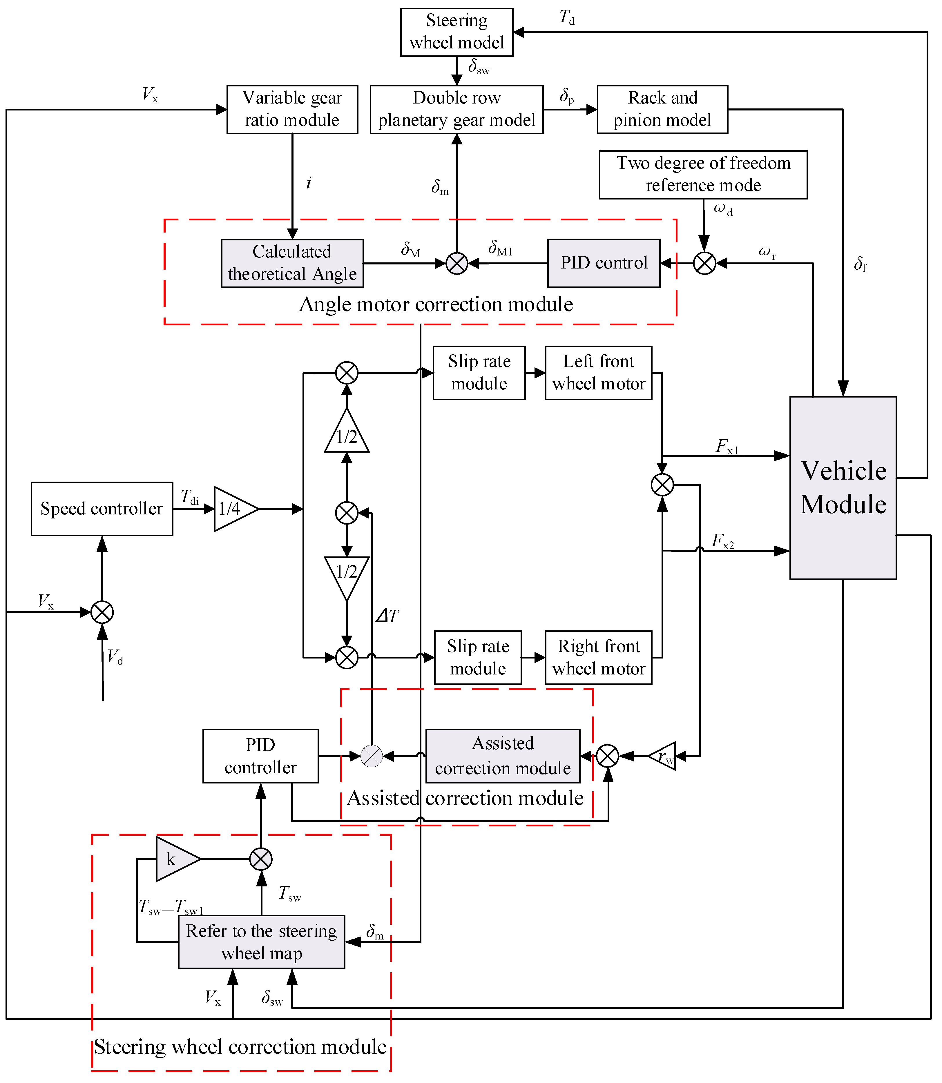
5.2. Coordinated Control Strategy Design

The coordinated control strategy developed in this article is shown in Figure 9. Develop an angle motor correction module based on yaw velocity feedback control to eliminate the impact of the DDAS system on vehicle steering characteristics. A correction turning angle has been added based on the theoretical turning angle to make the vehicle’s steering process closer to the ideal turning. Develop a steering wheel torque correction module to eliminate sudden torque changes and severe steering wheel shaking during AFS system intervention. Design a power assist correction module to eliminate the adverse effects of tire nonlinearity and other factors on the power assist system, ensuring the effectiveness of DDAS power assistance.

6. Simulation Analysis and Verification

To verify the effectiveness of the strategy, Carsim and MATLAB/Simulink co-simulation were carried out in this paper. The main simulation parameters are shown in Table 1.

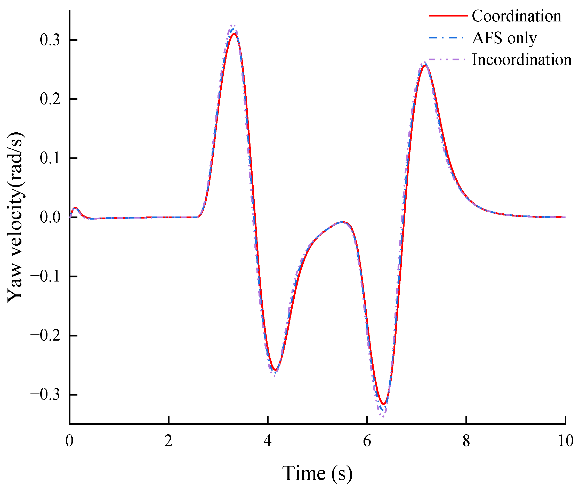
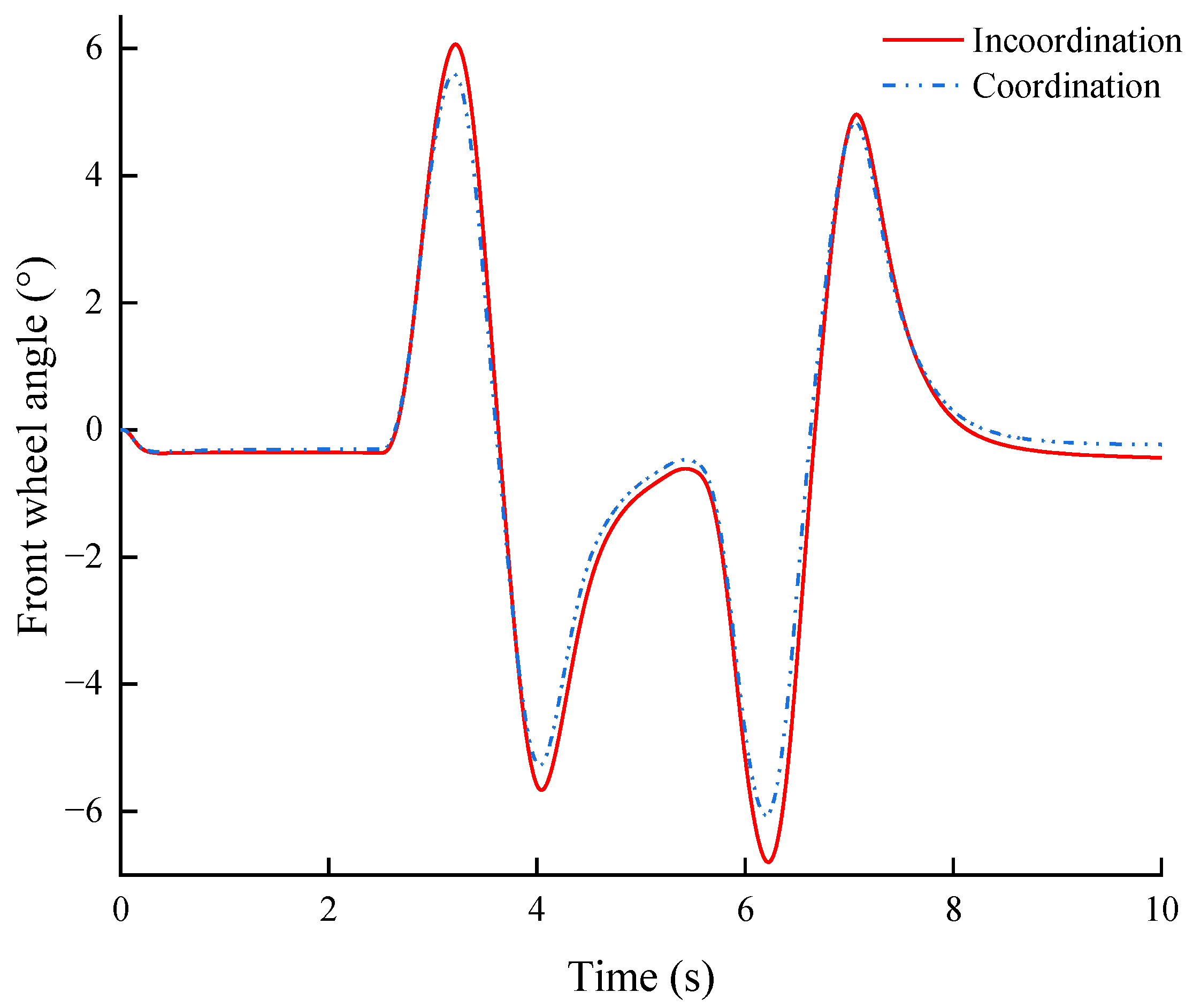
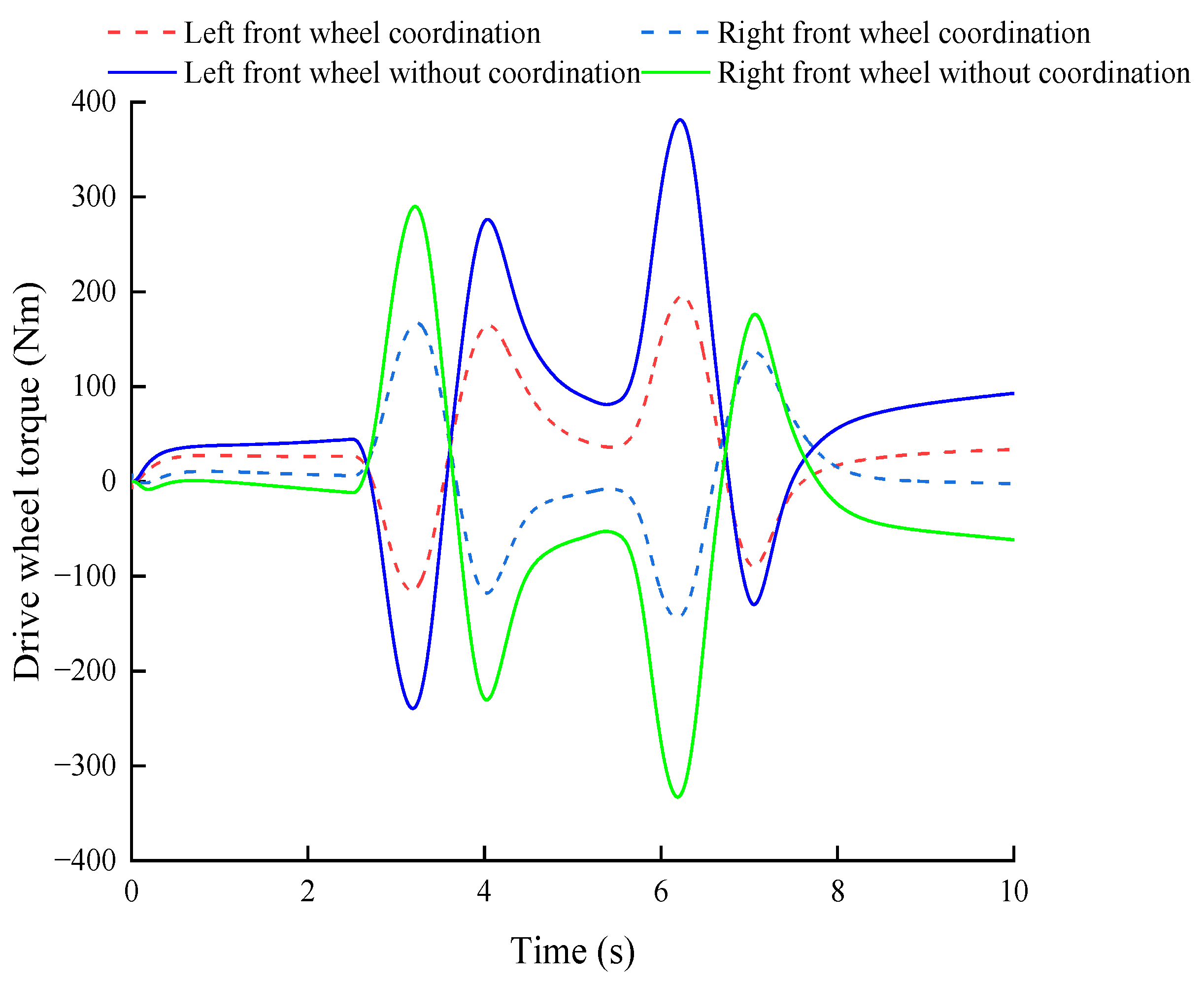
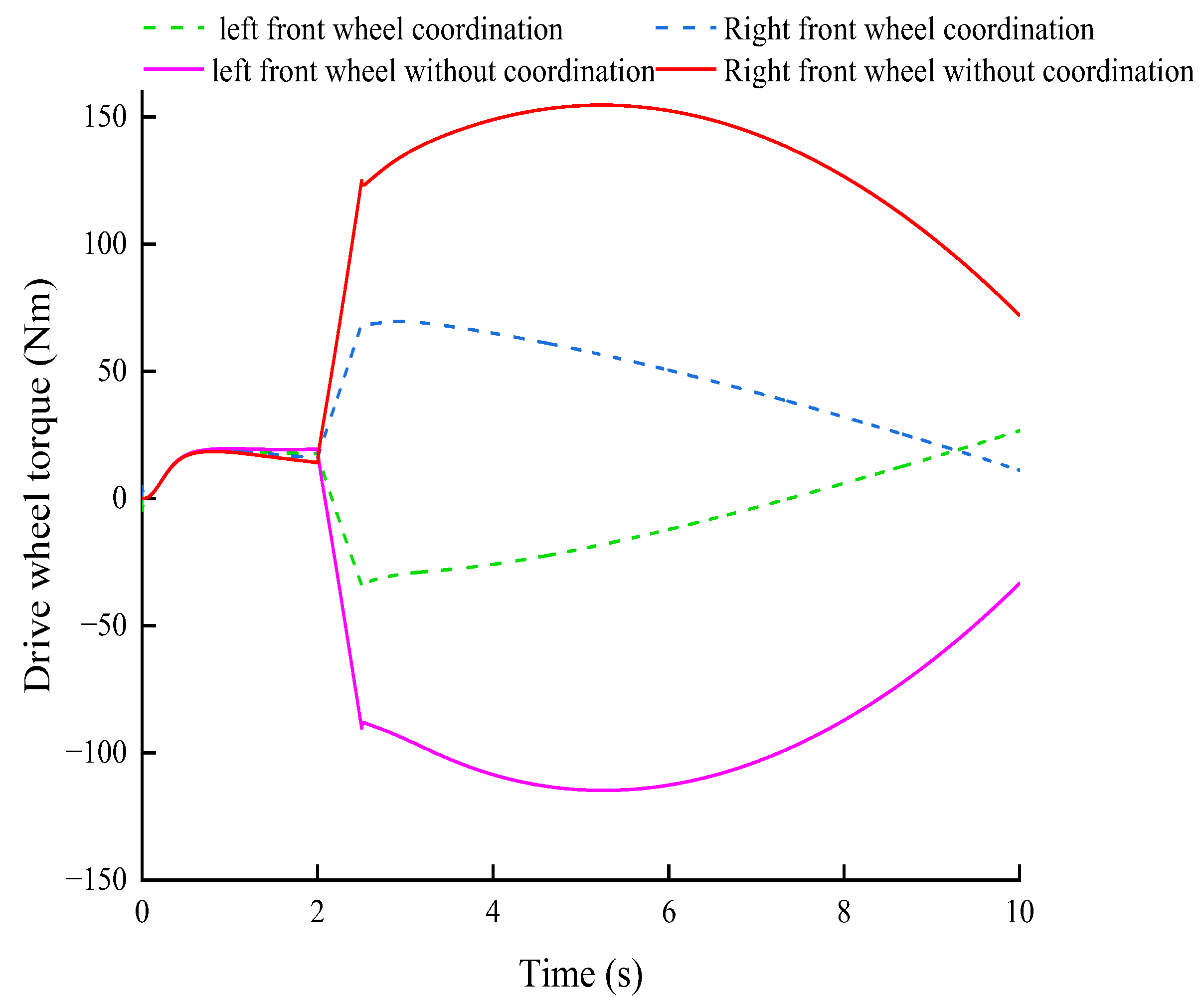
6.1. Verification of Double Lane Change

To verify the effectiveness and feasibility of the coordinated control strategy developed in this article and whether DDAS reduces its impact on AFS, a double lane change test was conducted at 60 km/h. As shown in Figure 10, there is an error diagram between uncoordinated and coordinated effects. From the figure, it can be seen that the average error after coordination decreased by 0.01 rad/s compared to without coordination. The average error confirms the effectiveness of the coordination strategy for the vehicle, meets the conditions of use of the vehicle stability control system, and avoids vehicle safety accidents when turning. Table 2 shows the variation of peak value before and after yaw velocity and front wheel angle coordination. As seen from Figure 11 and Table 2, The peak value of vehicles with coordinated control is reduced by 4% compared to those without coordinated control, and cars with coordinated control can better track the ideal yaw velocity. The peak value of AFS working alone is reduced by 2.4% compared to the uncoordinated peak value. When the DDAS system is working, the introduction of yaw moment leads to an increase in yaw rate, which affects the lateral stability of the vehicle and thus affects its steering characteristics.
Figure 12 shows a comparison of the front wheel angle, where the peaks and troughs with coordination are reduced by 7.8% compared with those without coordination. The decrease in front wheel angle reduces steering resistance, thus reducing the demand for assistance. Figure 13 shows that the difference in driving torque between the left and right front wheels using coordinated control has been reduced by 42%, demonstrating the effectiveness of coordinated control.

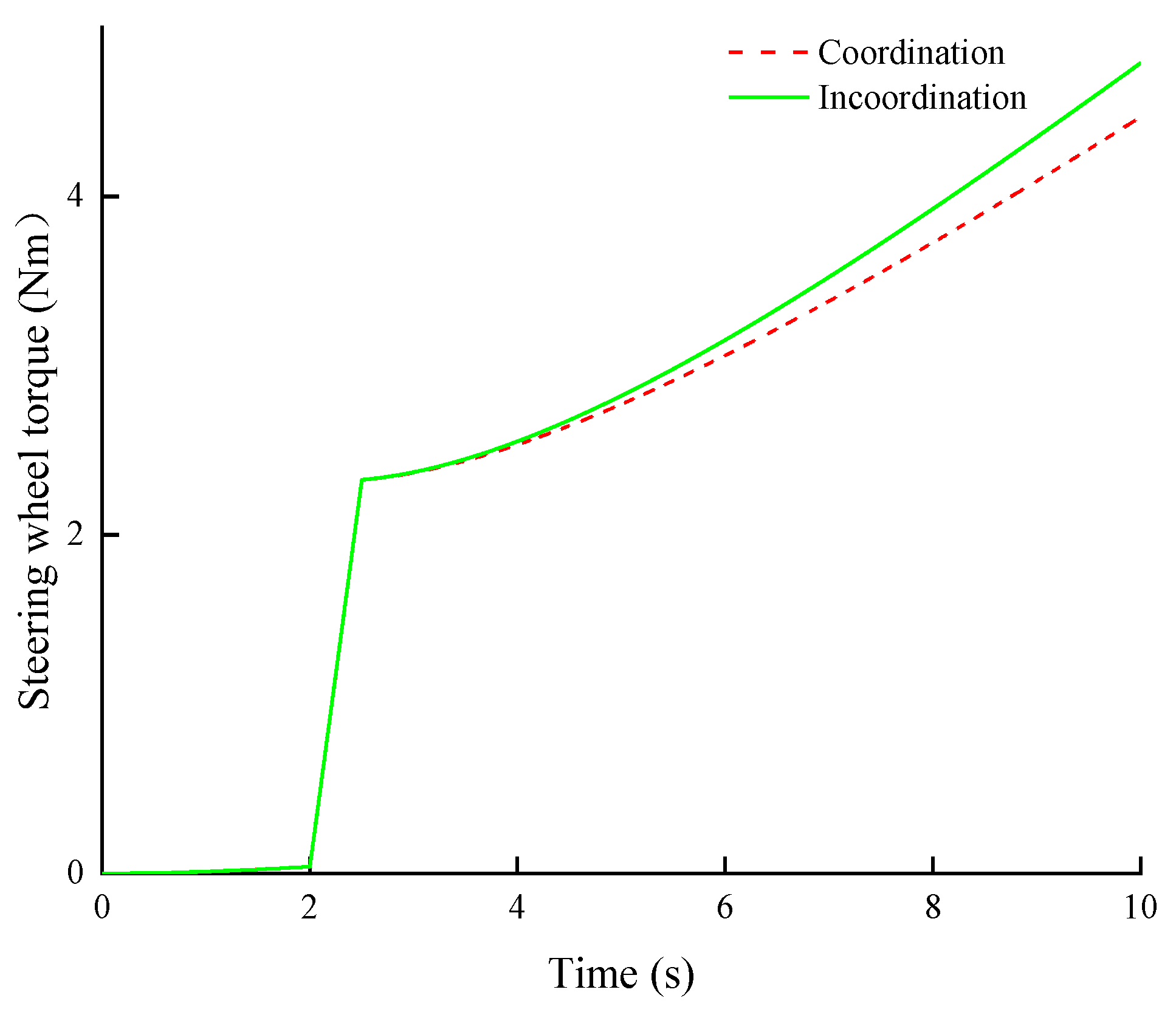
6.2. Verification of Angle Step Input

To verify whether the coordinated control strategy developed in this article can reduce the impact of the AFS system on the DDAS system, perform step condition verification on the steering system. Perform step condition verification at a speed of 60 km/h. Starting from second 2, turn the steering wheel to 57° after fixing. As can be seen from Figure 14, the peak and trough of steering wheel torque with coordinated control is reduced by about 6.7% compared with that without coordinated control, effectively suppressing the problem of steering wheel torque sudden change during AFS system operation. The coordinated control strategy developed in this paper has a steering wheel torque correction module. Figure 14 shows that the steering wheel torque with coordinated control is reduced by 0.32 Nm. As can be seen from Figure 15, compared with the one without coordinated control, the torque of the left and right front wheel drive is reduced by 44.7% when using coordinated control. This is because this strategy has a power correction module, which increases the power demand.

7. Conclusions

  • A coupled dynamic model of the DDAS system integrating active steering function was established. On this basis, an AFS controllers based on yaw velocity feedback control and DDAS controllers based on steering wheel torque control were designed, respectively;
  • The factors and causes of mutual interference between DDAS and AFS systems were analyzed, and a collaborative control strategy for DDAS and AFS was developed. A corner motor correction module was built to correct the corners to reduce the impact of the DDAS system on vehicle steering performance. A steering wheel torque correction module was established to correct the steering wheel torque to reduce the effects of AFS on the DDAS system. A power correction module has been built to enhance the collaborative control effect;
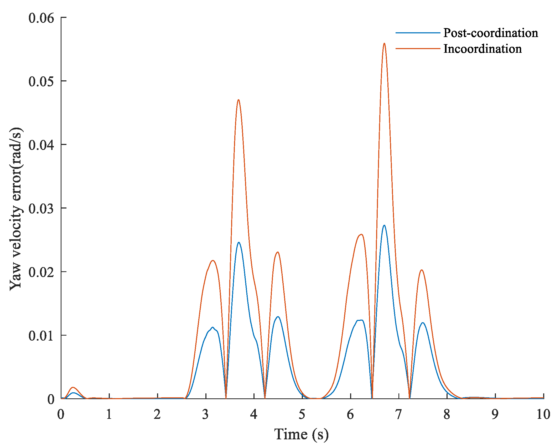
  • In the co-simulation, the yaw velocity with coordinated control decreases by 4% compared with that without coordinated control under the double-shift condition. The peak value of AFS working alone is reduced by 2.4% compared to uncoordinated work. Under step operating conditions, the steering wheel torque using coordinated control is reduced by 0.32 Nm. The strategy’s effectiveness was verified under typical operating conditions, and it improved the vehicle’s handling stability and steering portability;
  • This article provides a coordinated control strategy that is valuable for developing a DDAS system that integrates AFS. In future scientific research, it will be necessary to address the impact of DDAS on stability. Based on the characteristics of AFS and DYC systems, the coordinated control strategy of the system needs to be improved to prioritize ensuring the stability of vehicles during driving.

Author Contributions

Conceptualization, Z.Z.; manuscript writing, X.D. image description, Z.S. All authors have read and agreed to the published version of the manuscript.

Funding

This work is supported by the National Natural Science Foundation of China (51805149), the Major Project of Henan Province in 2022 (221100240400), and the major project of Ningbo Science and Technology Innovation 2025, “Development of Light Electric Vehicle Hub Motor and Control System” (2019B10073).

Data Availability Statement

Not applicable.

Conflicts of Interest

The authors declare no conflict of interest.

References

  1. Wang, J.; Wang, Q.; Jin, L.; Song, C. Independent wheel torque control of 4WD electric vehicle for differential drive assisted steering. Mechatronics 2011, 21, 63–76. [Google Scholar] [CrossRef]
  2. Jin, L.Q.; Wang, J.N.; Song, C.X.; Hu, C. Power Steering by Driving Force for Vehicle with Motorized Wheels. J. Mech. Eng. 2010, 3, 101–108. [Google Scholar] [CrossRef]
  3. Wang, J.N.; Wang, Q.N.; Song, C.X.; Jin, L.Q.; Hu, C.J. Co-simulation and Test of Differential Drive Assist Steering Control System for Four-wheel Electric Vehicle. J. Agric. Mach. 2010, 3, 7–13+30. [Google Scholar]
  4. Reinelt, W.; Klier, W.; Reimann, G.; Schuster, W.; Großheim, R. Active front steering (part 2): Safety and functionality. In Proceedings of the 2004 SAE World Congress, Detroit, MI, USA, 8–11 March 2004; pp. 1–9. [Google Scholar]
  5. Chen, L.; Yuan, C.Y.; Jiang, H.B.; Kai, X.; Shaohua, W. Self-adaptive Fuzzy Parameter Integrated Control of Automotive Active Suspension and Steering Systems. China Mech. Eng. 2006, 3, 2525–2528. [Google Scholar]
  6. Chen, W.; Xiao, H.; Jean, W. Hierarchical control of automotive electric power steering system and anti-lock brake system: Theory and experiment. Int. J. Veh. Des. 2012, 59, 23–43. [Google Scholar] [CrossRef]
  7. Wang, J.; Luo, Z.; Wang, Y.; Yang, B.; Assadian, F. Coordination Control of Differential Drive Assist Steering and Vehicle Stability Control for Four-Wheel-Independent-Drive EV. IEEE Trans. Veh. Technol. 2018, 67, 11453–11467. [Google Scholar] [CrossRef]
  8. Zhong, Z.H.; Xiao, Z.; Xiong, L.; Yang, X. Design of Differential Drive Assist Steering Controller Based on In-Wheel Motor Drive Electric Vehicle. J. Tongji Univ. Nat. Sci. 2017, 45, 47–52+104. [Google Scholar]
  9. Yu, Z.P.; Leng, B. Differential Drive Assisted Steering Control for Distributed Drive electric Vehicles. Automot. Eng. 2017, 3, 243–248+295. [Google Scholar]
  10. Lu, S.F.; Xu, X.; Chen, L.; Feng, W.; Wujie, W. Coordinated Control of Electronic Differential and Differential Drive Assisted Steering for Vehicle Driven by Hub Motor. Chin. J. Mech. Eng. 2017, 3, 78–85. [Google Scholar] [CrossRef]
  11. Wang, J.; Wang, X.; Luo, Z.; Assadian, F. Active Disturbance Rejection Control of Differential Drive Assist Steering for Electric Vehicles. Energies 2020, 13, 2647. [Google Scholar] [CrossRef]
  12. Cheng, X.; Chen, T.; Li, J.; Wang, J. Coordinated Control Method for Lateral Stability and Differential Power-Assisted Steering of In-Wheel Motor Drive Electric Vehicles. World Electr. Veh. J. 2023, 14, 200. [Google Scholar] [CrossRef]
  13. Chen, D.L. Research on Control of Active front Steering System. Ph.D. Thesis, Shanghai Jiao Tong University, Shanghai, China, 2008. [Google Scholar]
  14. Gao, Z.H.; Wang, J.; Wang, D.P. Dynamic Modeling and Steering Performance Analysis of Active Front Steering System. In Proceedings of the 2011 International Conference on Advanced in Control Engineering and Information Science CEIS 2011, Dali, China, 18–19 August 2011; Elsevier: Amsterdam, The Netherlands, 2011; Volume 2, pp. 1030–1035. [Google Scholar]
  15. Doumiati, M.; Sename, O.; Dugard, L.; Martinez-Molina, J.-J.; Gaspar, P.; Szabo, Z. Integrated vehicle dynamics control via coordination of active front steering and rear braking. Eur. J. Control 2013, 3, 121–143. [Google Scholar] [CrossRef]
  16. Ding, N.G.; Kang, L.; Wang, J.; Yu, G.-Z. Optimal control of active front steering for automobiles under lateral wind interference. J. Beijing Univ. Technol. 2013, 39, 161–165. [Google Scholar]
  17. Gao, X.J.; Yu, Z.P.; Zhang, L.J. The principle and Application of Mechanical Active Front Steering System. Automot. Eng. 2006, 3, 918–921932. [Google Scholar]
  18. Sang, N.; Wei, M.X. Design of ESO and N TSM controller for vehicle active front steering. J. Nanjing Univ. Aeronaut. Astronaut. 2018, 50, 521–527. [Google Scholar]
  19. Li, S.; Guo, K.; Chou, T.; Chen, H.; Wang, G.; Cui, G. Stability control of vehicle with active front steering under extreme conditions. Automot. Eng. 2020, 3, 191–198. [Google Scholar]
  20. Zhang, N.; Wang, J.; Li, Z.; Li, S.; Ding, H. Multi-Agent-Based Coordinated Control of ABS and AFS for Distributed Drive Electric Vehicles. Energies 2022, 15, 1919. [Google Scholar] [CrossRef]
  21. Wang, C.Y.; Cui, T.W.; Zhao, W.Z.; Chen, J. Active front Steering Control based on Ideal Transmission Ratio. Trans. Chin. Soc. Agric. Eng. 2015, 31, 85–90. [Google Scholar]
  22. Zheng, H.; Li, J.; Zong, C.; Yuan, K.; Zhao, J.; Hou, J. Optimization design of vehicle yaw rate gain for steer-by-wire. J. Jilin Univ. Eng. Technol. Ed. 2012, 42, 7–12. [Google Scholar]
  23. Shang, G.G.; Hong, Z.; Zhang, H.D.; Luo, S.; He, R. Variable transmission ratio model of active steering system based on steady-state gain. J. Jiangsu Univ. Nat. Sci. Ed. 2010, 3, 278–282. [Google Scholar]
  24. Zhou, B.; Fan, L.; Lu, X.N. Design of Modified Variable Steering Ratio Curve for Active Front Steering System. China Mech. Eng. 2014, 25, 2813–2818. [Google Scholar]
  25. Wang, C.; Zhao, W.; Liu, S.; Sun, P. Parameter optimization of electric power steering integrated with active front steering function. Trans. Nanjing Univ. Aeronaut. Astronaut. 2012, 3, 96–102. [Google Scholar]
  26. Minaki, R.; Hoshino, H.; Hori, Y. Ergonomic verification of reactive torque control based on driver’s sensitivity characteristics for active front steering. In Proceedings of the Vehicle Power and Propulsion Conference 2009 VPPC 2009, Dearborn, MI, USA, 7–11 September 2009; pp. 160–164. [Google Scholar]
  27. Minaki, R.; Hori, Y. Experimental verification of driver-friendly reactive torque control based on driver sensitivity to active front steering. In Proceedings of the 2009 35th Annual Conference of IEEE Industrial Electronics, Porto, Portugal, 3–5 November 2009; pp. 3077–3082. [Google Scholar]
  28. Zhou, B.; Xu, M.; Fan, L. AFS and EPS Integrated Control Based on EKF Tire Lateral Force Estimation. J. Vib. Shock 2015, 34, 93–98. [Google Scholar]
  29. Wei, J.W.; Wei, M.X.; Li, Y.F. EPS Assisted Correction Control Strategy and Evaluation for Active Steering Intervention. China Mech. Eng. 2012, 3, 1873–1876. [Google Scholar]
  30. Wei, J.W.; Wei, M.X. Correction strategy for sudden change of steering wheel torque in EPS System based on active steering Intervention. J. Nanjing Univ. Aeronaut. Astronaut. 2011, 3, 572–576. [Google Scholar]
  31. Wang, J.N.; Guo, D.D.; Yan, T.X.; Assadian; Francis; Luo, Z. Coordinated Control of DDAS and AFS in Electric Vehicles. J. Jilin Univ. Eng. Ed. 2020, 3, 776–783. [Google Scholar]
  32. Jilin University. Differential Collaborative Active Steering System and Its Control Method for Electric Wheel Front Axle Independent Drive Vehicles; CN201911238318.2, 6 March 2020; Jilin University: Changchun, China, 2020. [Google Scholar]
  33. Wei, J.; Shi, G.; Lin, Y. Design of new variable steering ratio for mechanical active steering system. In Proceedings of the 2013 IEEE International Conference on Vehicular Electronics and Safety, Dongguan, China, 28–30 July 2013; IEEE Press: New York, NY, USA, 2013; pp. 27–30. [Google Scholar]
  34. Yu, Z.P.; Zhao, Z.G.; Chen, H. Influence of active front steering on vehicle maneuver and stability performance. China Mech. Eng. 2005, 3, 652–657. [Google Scholar]
  35. Guo, K.H. Automotive Handling Dynamic; Jilin Science and Technology Press: Changchun, China, 1991. [Google Scholar]
  36. Xiao, B. The Research of Fuzzy Variable Transmission Ratio for Steer-by-wire System of Electric Forklift. Int. J. Intell. Syst. Appl. IJISA 2015, 7, 31–39. [Google Scholar] [CrossRef]
  37. Shi, G.B.; Zhao, W.Z.; Wang, C.L.; Li, Q.; Lin, Y. Influence of Variable Steering Ratio for Steering by-wire System on Vehicle Handling Stability. Trans. Beijing Inst. Technol. 2008, 28, 207–210. [Google Scholar]
  38. Zhang, Y.K.; Liu, B.H. Study on the Active Front Steering System with Steady Gain. In Proceedings of the FISITA 2012 World Automotive Congress, Beijing, China, 27–30 November 2012; Springer: Berlin/Heidelberg, Germany, 2012; pp. 65–74. [Google Scholar]
Figure 1. DDAS system integrating AFS system.
Wevj 14 00292 g001
Figure 2. Double-row PGT.
Wevj 14 00292 g002
Figure 3. Two-degree-of-freedom vehicle model.
Wevj 14 00292 g003
Figure 4. Single point preview PID control driver model.
Wevj 14 00292 g004
Figure 5. Transmission ratio diagram.
Wevj 14 00292 g005
Figure 6. AFS system control block diagram.
Wevj 14 00292 g006
Figure 7. Reference steering wheel torque MAP.
Wevj 14 00292 g007
Figure 8. Direct control strategy of DDAS system.
Wevj 14 00292 g008
Figure 9. Overall coordination control strategy.
Wevj 14 00292 g009
Figure 10. Average error before and after coordination.
Wevj 14 00292 g010
Figure 11. Comparison of yaw velocity.
Wevj 14 00292 g011
Figure 12. Comparison of front wheel angles.
Wevj 14 00292 g012
Figure 13. Comparison of drive torque.
Wevj 14 00292 g013
Figure 14. Comparison of steering wheel torque.
Wevj 14 00292 g014
Figure 15. Comparison of drive torque.
Wevj 14 00292 g015
Table 1. Steering system parameters.
ParameterUnitValue
Moment of inertia steering shaftJc/(kg.m2)0.04
Steering shaft damping coefficientBc/(Nm.s/rad)0.0225
Steering shaft torsional stiffnessKc/(Nm.s/rad)150
Pinion radiusrp/m0.0078
Moment of inertia of reducerJe/(kg.m2)0.6
Damping coefficient of reducerBe/(Nm.s/rad)0.02
Motor moment of inertiaJm/(kg.m2)0.006
Motor reduction mechanism steering ratioim30
Forward transmission efficiency of steering gearηF0.9
Reverse transmission efficiency of steering gearηB0.7
Kingpin inclination angleσ/(°)8
Kingpin caster angleτ/(°)3
Lateral offset of the main pinrσ/(°)0.07
Table 2. Coordinate peak changes before and after.
ParameterIncoordinationCoordination
Yaw velocity/(rad)0.3260.313
Front-wheel angles/(°)6.0625.591
Disclaimer/Publisher’s Note: The statements, opinions and data contained in all publications are solely those of the individual author(s) and contributor(s) and not of MDPI and/or the editor(s). MDPI and/or the editor(s) disclaim responsibility for any injury to people or property resulting from any ideas, methods, instructions or products referred to in the content.

