Article

Armature Reaction Analysis and Performance Optimization of Hybrid Excitation Starter Generator for Electric Vehicle Range Extender

1
School of Computer Science and Technology, Shandong University of Technology, Zibo 255049, China
2
Department of Automotive Engineering, Shandong Vocational College of Science and Technology, Weifang 261053, China
3
School of Transportation and Vehicle Engineering, Shandong University of Technology, Zibo 255049, China
4
Research and Development Center, Shandong Hapuwo Power Technology Co., Ltd., Zibo 255300, China
*
Author to whom correspondence should be addressed.
World Electr. Veh. J. 2023, 14(10), 286; https://doi.org/10.3390/wevj14100286
Submission received: 27 July 2023 / Revised: 6 September 2023 / Accepted: 28 September 2023 / Published: 10 October 2023

Abstract

:
The armature reaction of the hybrid excitation starter generator (HESG) under load conditions will affect the distribution of the main magnetic field and the output performance. However, using the conventional field-circuit combination method to study the armature reaction has the problem of low accuracy and inaccurate influencing factors. Therefore, this paper proposed a graphical method to analyze the armature reaction and a new type of HESG with a combined-pole permanent magnet (PM) rotor and claw-pole electromagnetic rotor. The analytical formula of the voltage regulation rate under the armature reaction was derived using the graphical method. The main influencing parameters of the armature reaction magnetic field (ARMF) were analyzed, and the overall output performance was analyzed using finite element software. On this basis, comparison analyses before and after optimization and the prototype test were carried out. The results show that the direct-axis armature reaction reactance, quadrature-axis armature reaction reactance, and voltage regulation rate of the optimized HESG were significantly reduced, the output voltage range of the whole machine was wide, and the voltage regulation performance was good.

1. Introduction

With increasingly severe environmental pollution and the depletion of fossil energy, electric vehicles have become the main development direction of transforming and upgrading the vehicle industry [1,2,3,4]. The extended-range electric vehicle adds a range extender basis to the pure electric vehicle, which allows the engine in the range extender to drive the generator to provide power for the power battery and the drive motor when the power battery level is too low. This method effectively improves the vehicle’s driving range [5]. The starter generator for the range extender has two functions: starting the engine and generating electric energy. It is one of the key components of the extended-range electric vehicle. Its output performance has an important influence on the power and safety of the vehicle [6,7,8]. Therefore, it has received extensive attention from experts and scholars. The hybrid excitation starter generator (HESG) uses the permanent magnet (PM) and the electric excitation coil to generate the magnetic field. Compared with the pure PM starter generator, its main magnetic field can be adjusted, and the voltage regulation performance is good. Compared with the pure electric excitation starter generator, it reduces the excitation power and has the advantages of less excitation loss and high efficiency [9,10,11,12]. It has become an important development direction of the starter generator for electric vehicle range extenders.
When the HESG runs under the load condition, the armature winding will induce the armature reaction magnetic field (ARMF). This magnetic field will form a magnetic circuit through the stator core, the main air gap, and the rotor core, which will affect the size and distribution of the main magnetic field. That effect is usually analyzed by the ratio of the difference between the output voltage of the load condition and the output voltage of the no-load condition to the rated load voltage, that is, the voltage regulation rate [13,14]. Refs. [15,16] established a mathematical model of the voltage regulation rate of the built-in PM starter generator under pure resistance load conditions. The results showed that the voltage will increase with the load when the starter generator has an anti-convex polarity. On this basis, Refs. [17,18,19] used the field-circuit combination method to analyze and verify that the anti-convex polarity of the rotor will produce a voltage self-compensation effect when the pure resistance load is applied. According to this characteristic, the voltage regulation rate can be reduced. In Ref. [20], the calculation models of electromagnetic characteristic parameters, such as the self-inductance and mutual inductance of armature winding under the condition of armature winding open circuit and armature reaction, were established. Based on this, the subdomain method was used to study the magnetic density model of the main magnetic field and ARMF of a radially magnetized PM structure, and the finite element method was used to verify it. Ref. [21] studied the influence of the armature reaction on the output performance of PM starter generators with different rotor structures. The influence of different pole numbers and slot numbers on the output performance of the starter generator was analyzed using the finite element method. Ref. [22] used the field-circuit combination method to study the calculation model of the voltage regulation rate of the PM starter generator. The effects of air gap length, stator slot shape, and stator core length on the voltage regulation rate were quantitatively analyzed, and the optimal parameters were selected to reduce the impact of armature reaction on the main magnetic field. Further, the model was verified by the finite element method. Ref. [23] established a calculation model of the external characteristics of the hybrid excitation PM starter generator. Based on this analysis, it was obtained that adjusting the power factor, reducing the armature winding resistance, and the armature reaction direct-axis reactance can reduce the voltage regulation rate of the starter generator. Ref. [24] established the expression of the voltage regulation rate of the built-in PM starter generator and studied the influence of structural parameters on the voltage regulation rate. Ref. [25] deduced the mathematical model of the voltage regulation rate of the radially magnetized PM starter generator and revealed the influence of the rotor core length, the size of the magnetic air gap, the coercivity of the PM, and the main air gap length on the voltage regulation rate. The equivalent magnetic circuit model of single-phase HESG was established in [26]. The main parameters of the motor were calculated using the analytical method, and the influence of the main structural parameters on the voltage regulation rate was revealed.
As indicated by above research status, most scholars have established the mathematical model of ARMF and voltage regulation rate using the field-circuit combination method to analyze the influence of the main structural parameters on the voltage regulation rate. However, the field-circuit combination method mostly involves the magnetic circuit structure, and the description accuracy of armature reaction factors is relatively low. In this paper, the graphical method is used to derive the analytical model of the voltage regulation rate, and the armature reaction reactance and impedance are solved to obtain a detailed analytical formula of the voltage regulation rate. Based on the solution method of armature reaction reactance, the influence of the main influencing parameters on the armature reaction and voltage regulation rate is studied.

2. Analysis of Armature Reaction of HESG

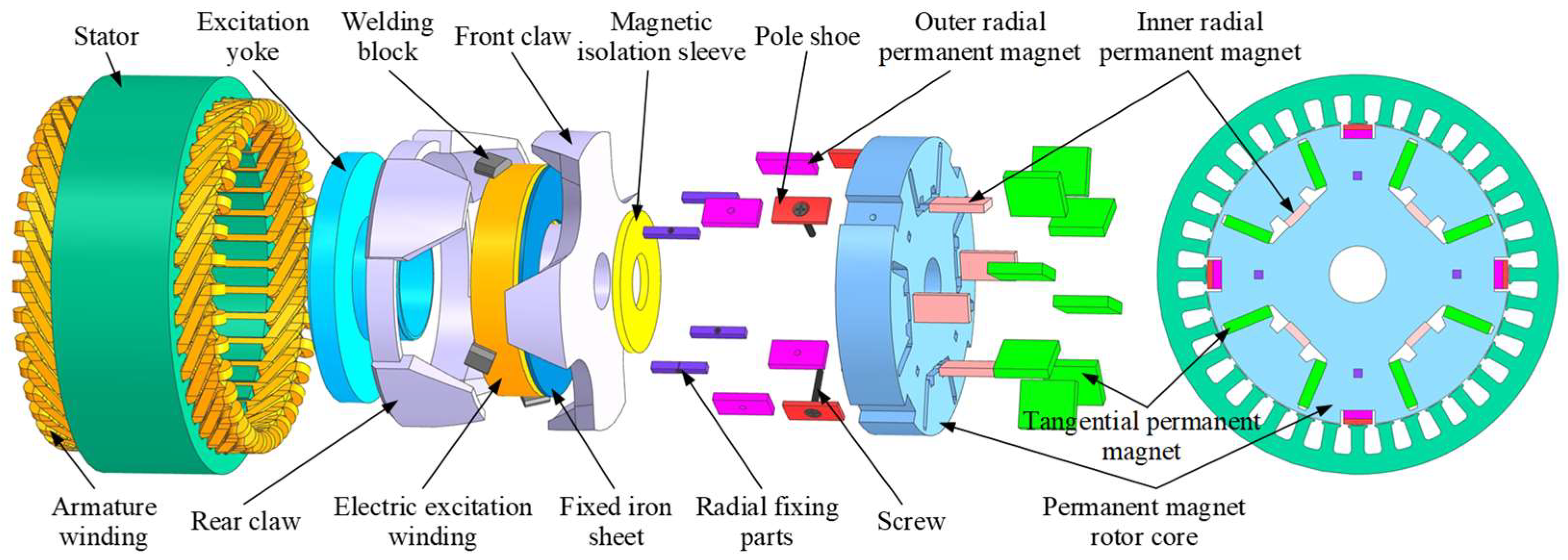
In this paper, a combined-pole PM and brushless electromagnetic HESG is proposed. The structure is shown in Figure 1. The starter generator adopts a parallel structure with a coaxial PM rotor and an electric excitation rotor. The PM magnetic field and electric excitation magnetic field do not interfere with each other in the rotor part and are synthesized in the main air gap. The structure can flexibly design the power of the PM part and electric excitation part to achieve a reasonable state of regulation characteristics and output efficiency.
Figure 1 shows that the electric excitation rotor of the designed HESG adopts a brushless claw-pole structure, which eliminates the carbon-brush slip ring and effectively improves the reliability of the whole machine. The PM rotor adopts a combined-pole structure, with outer and inner combined PMs designed in the middle of the uniformly distributed tangential PM. The main rotor magnetic field is mainly provided by the tangential PM, and the combined PMs at the center of the magnetic pole are used to improve the magnetic field strength. The combined PM outside the center of the magnetic pole is designed as a surface-mounted PM structure with a pole shoe, and the surface-mounted PM is fixed with screws and rivets. The structure can effectively reduce the demagnetization problem of PM caused by ARMF. At the same time, the magnetic field of each pole of the rotor is provided by a combination of multiple PMs, and the rotor magnetic field will have high magnetic field strength and uniform magnetic field distribution.
The magnitude of the ARMF of the starter generator is mainly related to the armature winding and armature current. For the power generation state, the armature current is related to the output power and load of the power generation state. The influence of ARMF on the main air gap magnetic field is related to the nature of the load [27,28,
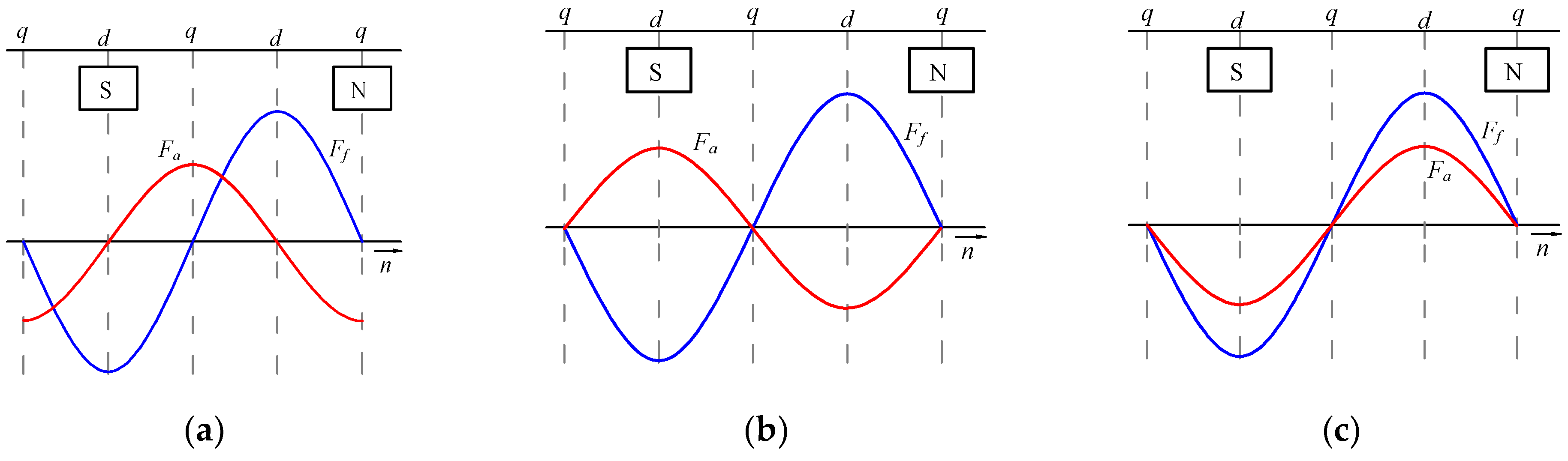
29]. When the internal power factor angle is 0°, the load current is in phase with the no-load induced electromotive force, and the load is a pure resistive load. The armature reaction electromotive force differs by 90° phase from the rotor electromotive force, showing an orthogonal relationship. At this time, the armature reaction is named the quadrature-axis armature reaction. When the internal power factor angle is 90°, and the load is a purely inductive load, the phase of the armature reaction magnetomotive force is the same as that of the rotor magnetomotive force, but the direction is opposite. When the internal power factor angle is −90° and the load is a pure capacitive load, the armature reaction magnetomotive force and rotor magnetomotive force have the same phase and direction. The armature reaction under the above two working conditions with an internal power angle of ±90° is named the direct-axis armature reaction. The relationship between the armature reaction magnetomotive force and the rotor magnetomotive force under the three different load properties mentioned above is shown in Figure 2.
From Figure 2a, it can be seen that the quadrature-axis ARMF plays a demagnetization role in the first half of the rotor magnetomotive force waveform, which weakens the rotor magnetomotive force, and plays a magnetization role in the second half of the rotor magnetomotive force waveform, which enhances the rotor magnetomotive force. Therefore, the quadrature-axis ARMF not only affects the magnitude of the rotor magnetomotive force but also affects its waveform. It can be seen from Figure 2b,c that the direct-axis ARMF only affects the size of the rotor magnetomotive force, which plays a role in magnetization or demagnetization. Overall, the ARMF can affect the main magnetic field’s size and distribution, reduce the output voltage under the load conditions, and affect the output performance of the whole machine.
For the HESG, the calculation of the voltage regulation rate does not consider the influence of the electric excitation magnetomotive force, and only the PM magnetomotive force is calculated. Therefore, the PM part is considered in the analysis, and the voltage regulation rate is calculated as [30,31,32]:
Δ U = E 0 U U N × 100 %
where E 0 is the output voltage of the no-load condition, U is the output voltage under rated load conditions, and U N is the rated voltage.
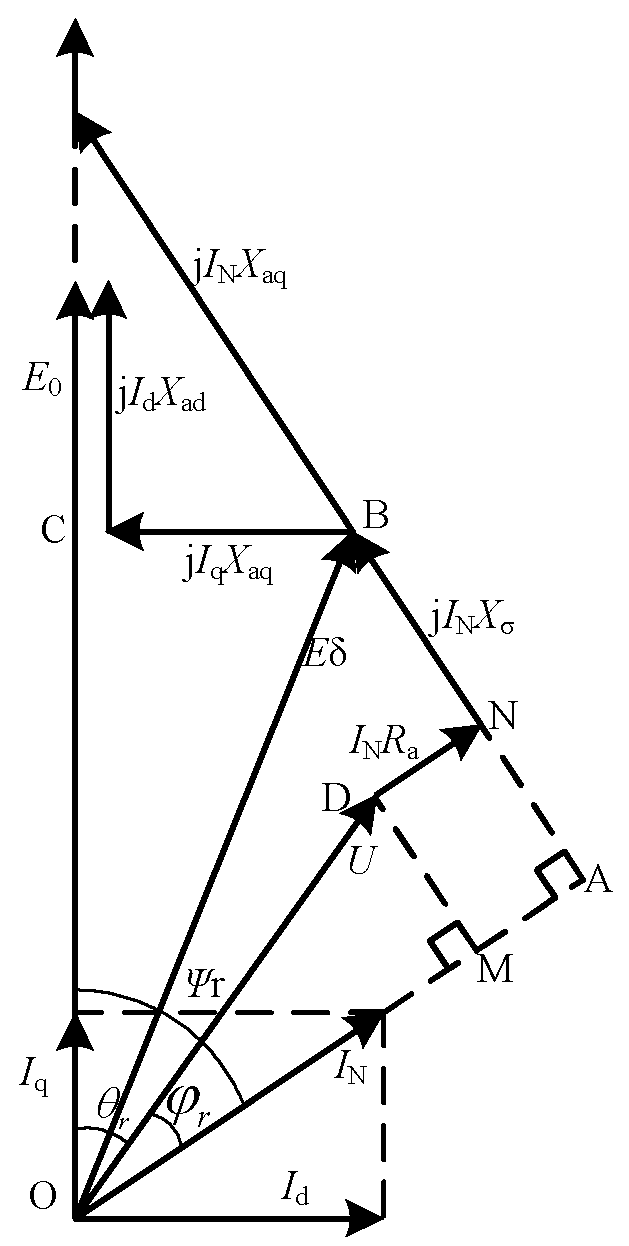
The voltage regulation rate can be calculated by the starter generator’s vector diagram, and the vector diagram of the starter generator under the condition of the resistive inductive load is shown in Figure 3.
In Figure 3, θ r is the power angle, φ r is the power factor angle, ψ r is the internal power factor angle, E δ is the magnetomotive force of main magnetic field, X ad is the direct-axis armature reaction reactance, X aq is the quadrature-axis armature reaction reactance, X σ is the stator leakage reactance, I N is the rated current of armature winding, I d is the current of direct-axis armature reaction, and I d = I N sin φ , I q is the current of quadrature-axis armature reaction; I q = I N cos φ .
As shown in the vector relationship in Figure 3, the left and right sides of the main magnetic field magnetomotive force are two right-angle triangles, respectively. One right-angle triangle is made by the main magnetic field magnetomotive force in the direction of the output current, which is composed of O point, A point, and B point. The other right-angle triangle is made by the main magnetic field magnetomotive force in the direction of no-load induced electromotive force, which is composed of O point, B point, and C point.
For the right-angle triangle OBC, according to the Pythagorean theorem, there are:
E 0 I d X ad 2 + I q X aq 2 = E δ 2
For the right-angle triangle OAB, according to the Pythagorean theorem, it can be obtained that:
U cos φ r + I N R a 2 + U sin φ r + I N X σ 2 = E δ
Combining Equations (2) and (3), and decomposing the quadrature-axis and direct-axis armature currents, the solution equation of the output voltage can be obtained as follows:
U cos φ r + I N R a 2 + U sin φ r + I N X σ 2 = E 0 I N X ad sin ψ r 2 + I N X aq cos ψ r 2
The analytical expression of the output voltage can be obtained by simplifying and sorting the formula as follows:
U = E 0 I N X ad sin ψ r 2 + I N X aq cos ψ r 2 I N 2 R a sin φ r X σ cos φ r 2 I N R a cos φ r + X σ sin φ r
The output voltage under no-load condition in the formula is calculated as the induced electromotive force of the starter generator under no-load condition, which is calculated as:
E 0 = 4.44 f N a K dp Φ δ 0 K Φ
where Φ δ 0 is the effective magnetic flux in the main air gap under the no-load condition, K dp is the winding coefficient of the armature winding, and K dp = K d K p K sk , where K d is the distribution coefficient of the armature winding, K p is the short distance coefficient of the armature winding, K sk is the skew slot coefficient of the stator, and K Φ is the waveform coefficient of air gap magnetic flux; K Φ = 8 π 2 α i sin α i π 2 , where α i is the calculated pole arc coefficient; and α i = α p + 4 / τ sto / δ + 6 / 1 α p , where τ sto is the stator pitch and α p is the pole arc coefficient. For the designed combined-pole PM rotor structure, the pole arc coefficient is calculated as the ratio of the arc length between the leakage magnetic areas of the adjacent built-in tangential PM outer end to the pole distance.
For the built-in PM rotor, due to the presence of a magnetic air gap or a rotor core on the outer side of the PM, its outer magnetic flux density is large, and the outer part is equivalent to the pole shoe effect. Therefore, the direct-axis and quadrature-axis armature reaction reactance can be calculated as follows [33]:
X aq = E 0 I N F aq F δ α p π sin α p π + 2 3 cos α p π 2 4 sin α p π 2 X ad = 4.4 f N a K dp K Φ I N sin ψ r ( Φ δ 0 Φ δ N )
where F aq is the quadrature-axis armature reaction magnetomotive force and F δ is the magnetomotive force in the main air gap; F δ = B δ δ K δ / μ 0 , where B δ is the magnetic flux density in the main air gap, K δ is the main air gap coefficient, and Φ δ N is the effective magnetic flux in the main air gap under rated load conditions.
The stator leakage reactance X σ is calculated as follows:
X σ = 15.5 f 100 ( N a 100 ) 2 L st p r q Σ λ × 10 4
where q is the number of slots per pole and per phase, and Σ λ is the stator specific leakage permeance; Σ λ = λ so + λ se + λ st ,where λ so is the stator slot specific leakage permeance, λ se is the stator end specific leakage permeance, λ d is the specific leakage permeance of the opening stator slot, and λ st is the specific leakage permeance of the tooth tip.
The specific leakage permeance of each part of the stator is related to the stator slot type and armature winding parameters. For the semi-open rectangular slot, the size parameters are shown in Figure 4.
Based on Figure 4, the specific leakage permeance of each part of the stator is calculated as follows:
λ so = 1 4 2 h 1 3 ( b s 2 + b ) + h 2 b + 3 β + 1.67 h 3 b s 1 + b + 3 β + 1 ( h 4 b s 1 + 2 h 5 b s 1 + b s 0 + h 6 b s 0 ) λ se = 0.34 q L st ( l se 0.64 τ st β ) λ d = α p 5 δ / b s 0 5 + 4 δ / b s 0 λ st = ( τ st b s 2 ) π D i 1 / Z b s 0 / 4 δ + b s 2 ( τ st b s 2 ) π D i 1 / Z b s 0 / 4 δ τ st
where h 1 , h 2 , h 3 , h 4 , h 5 , and h 6 are the heights of the relevant positions of the stator slot and armature winding distribution, as shown in Figure 4, b 1 and b 2 are the width of the stator slot wedge and slot top, and b is the central arc length of the stator slot; b = π D i 1 + h 2 + 2 h 3 + h 4 + h 5 + h 6 / Z , where D il is the inner diameter of the stator, Z is the number of stator slots, and β is the armature winding pitch ratio; and β = y / m q , where y is the armature winding pitch, l se is the length of the armature winding end, and τ st is the stator pole distance.
The voltage regulation rate of the HESG can be obtained:
U = 4.44 f N a K dp Φ δ 0 K Φ + I N R a cos φ r + X σ sin φ r E 0 I N X ad sin ψ r 2 + I N X aq cos ψ r 2 I N 2 R a sin φ r X σ cos φ r 2 U N
According to (8), the voltage regulation rate is mainly related to the ARMF, no-load main magnetic field, load working condition parameters, and magnetic conductivity parameters of the stator and rotor. In addition, reducing the voltage regulation rate should reduce the ARMF and make the output voltage reach the maximum value on the basis of ensuring the no-load induced electromotive force. When the power factor of the starter generator is determined, increasing the quadrature-axis armature reaction reactance, reducing the direct-axis armature reaction reactance, and reducing the armature winding resistance and stator leakage reactance can reduce the voltage regulation rate. Among them, the reactance of the quadrature-axis and direct-axis armature reactions is related to the rotor structure. For pure radial magnetized PM rotors, the PM is located at the center of the rotor’s direct-axis. Due to the high magnetic resistance of the PM itself, the influence of the quadrature-axis ARMF on the main air gap is relatively small. For a pure tangential magnetized PM structure, the PM is located at the center of the rotor’s quadrature-axis, and the quadrature-axis ARMF is distributed on both sides of the PM. Therefore, the armature reaction reactance of the tangential PM structure is larger, and the influence on the main air gap is also larger.
For the combined-pole PM rotor in this paper, the rotor is equipped with radial PM and tangential PM. The direct-axis ARMF mostly forms a magnetic circuit through the front and rear ends of the tangential PM, while the quadrature-axis ARMF forms a magnetic circuit near the combined PM at the center of the rotor magnetic pole. For the convenience of analysis, the ARMF is equivalent to the quadrature-axis and direct-axis ARMF, the armature reaction magnetomotive force is equivalent to the quadrature-axis and direct-axis armature reaction magnetomotive force, and the three-phase armature reaction current is equivalent to the quadrature-axis and direct-axis armature reaction current too. When the initial phase angle of the starter generator is zero, the three-phase current of the armature reaction can be calculated as follows:
i a = I m cos ω t i b = I m cos ω t 2 π / 3 i c = I m cos ω t + 2 π / 3
where I m is the phase current amplitude, and t is the running time of the starter generator.
When the running time of the starter generator is zero, the relationship between the three-phase currents is:
i a = I m i b = i c = I m 2
By Park transformation of the three-phase current, the quadrature-axis and direct-axis currents can be obtained as follows:
i d = 2 3 i a cos θ d + i b cos θ d 2 π / 3 + i c cos θ d + 2 π / 3 i q = 2 3 i a sin θ d + i b sin θ d 2 π / 3 + i c sin θ d + 2 π / 3 i 0 = 1 3 i a + i b + i c
where θ d is the angle between the axis of phase A armature winding and the axis of the direct-axis, and i 0 is the set current for balancing the three-phase current system.
The direct-axis and quadrature-axis armature reaction reactance of the starter generator can be calculated based on different working states. Among them, the direct-axis armature reaction reactance can be calculated based on the equivalent direct-axis state. In this state, θ d 
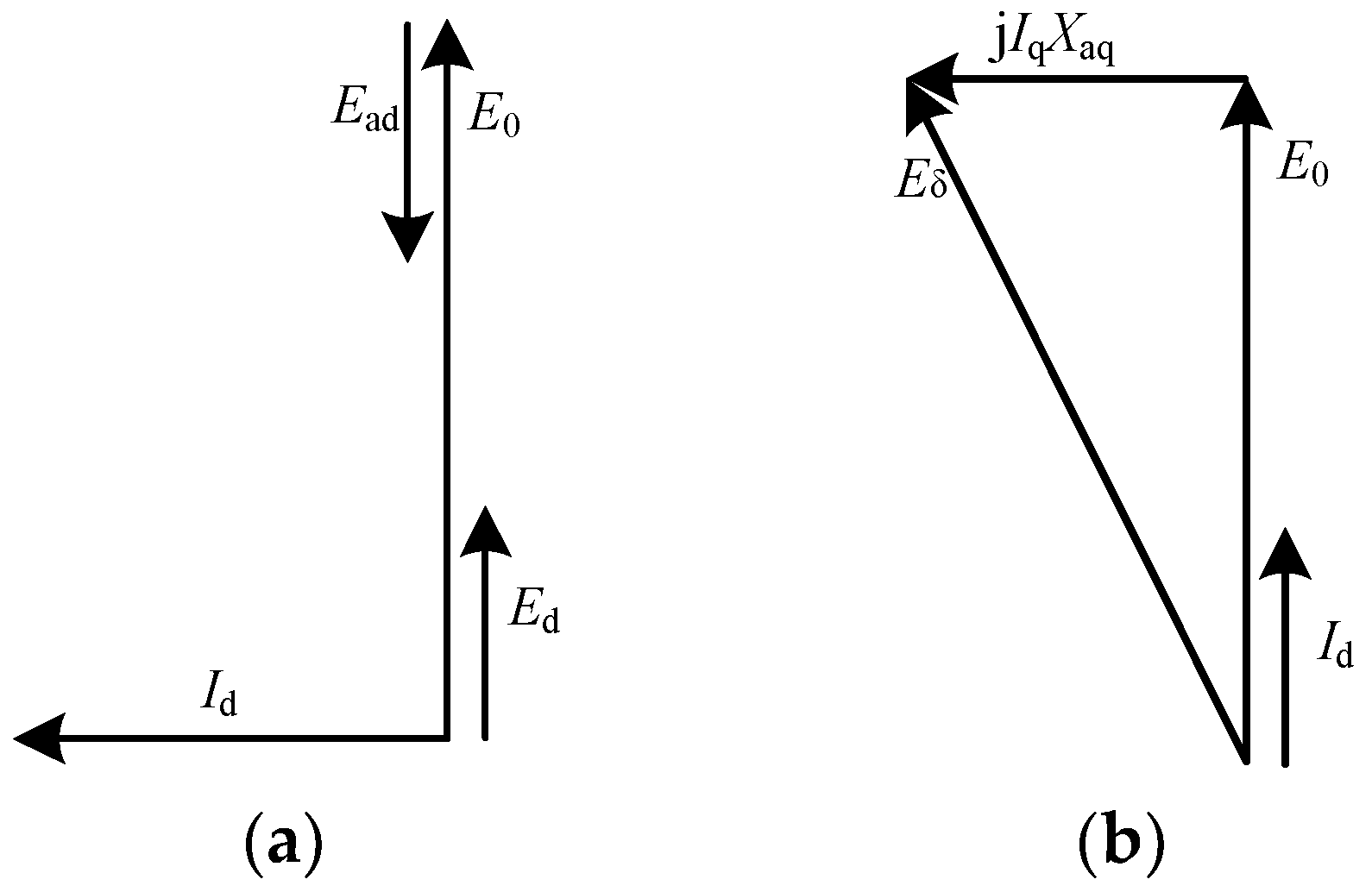
is set to zero. That is, the direct-axis of the rotor coincides with the axis of the A-phase armature winding. At this time, the armature winding current only has a direct-axis component, and there is no quadrature-axis component. The magnetic field distribution of the armature winding is the magnetic field distribution of the direct-axis armature winding, and the calculated reactance is the direct-axis armature reaction reactance. The quadrature-axis armature reaction reactance is calculated based on the equivalent cross-axis state, which sets the angle between phase A’s armature winding axis and the direct-axis to be 90°. At this time, the armature winding current only has the quadrature-axis component. The magnetic field of the armature winding in this state is the quadrature-axis ARMF, and the reactance parameter at this time is the quadrature-axis armature reaction reactance. The vector diagram of the equivalent direct-axis and the equivalent quadrature-axis states is shown in Figure 5.
It can be seen from Figure 5 that the induced electromotive force of the direct-axis armature reaction can be calculated as a scalar difference because the direct-axis armature reaction magnetic field only has the effect of increasing and weakening the main magnetic field. In contrast, the quadrature-axis armature reaction magnetic field not only affects the size of the main magnetic field but also affects its distribution. Therefore, the induced electromotive force of the quadrature-axis armature reaction must be calculated as a vector. The direct-axis and quadrature-axis armature reaction reactances are as follows:
X ad = E 0 E d I d X aq = E ˙ 0 E ˙ q I ˙ q
where E d is the direct-axis electromotive force, which is calculated as the electromotive force of the equivalent direct-axis state; E d = 4.44 f N A K dp Φ d , where Φ d is the fundamental magnetic flux per pole of the equivalent direct-axis state; and Φ d = 2 π τ r L st B δ d , where τ r is the rotor pole distance, B δ d is the fundamental amplitude of the air gap magnetic flux density in the equivalent direct-axis state, E ˙ 0 is the no-load induced electromotive force vector in the equivalent quadrature-axis state, E ˙ q is the quadrature-axis armature reaction electromotive force vector in the equivalent quadrature-axis state, and I ˙ d is the quadrature-axis armature reaction current vector.
In the calculation of direct-axis and quadrature-axis armature reaction reactance, since the direct-axis ARMF has only the effect of increasing and weakening the main magnetic field, the induced electromotive force can be calculated as the scalar difference when calculating the direct-axis armature reaction reactance, whereas the quadrature-axis ARMF not only affects the size of the main magnetic field but also affects its distribution. The induced electromotive force must be vector addition during the calculation of the quadrature-axis armature reaction reactance.
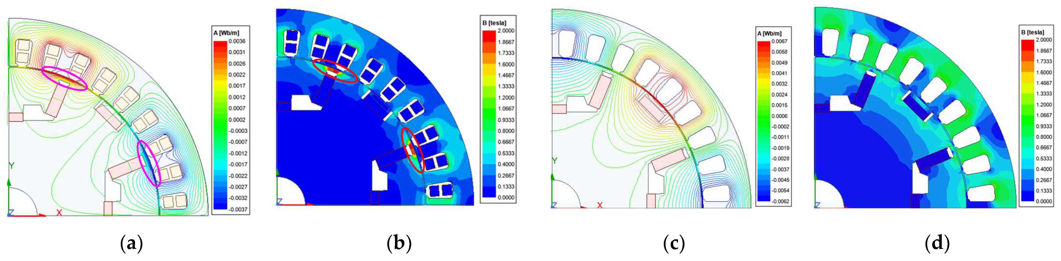
The finite element analysis model of the PM magnetic field is established, and the PM is set as the zero excitation source. Through simulation analysis, the magnetic field line distribution diagram and magnetic density cloud diagram of the equivalent direct-axis and quadrature-axis ARMF are obtained, as shown in Figure 6.
Figure 6 shows that the direct-axis ARMF mainly forms a magnetic circuit at the outer end of the tangential PM, and a small part passes through the tangential PM, the combined PM inside the magnetic pole center, and the magnetic gap between the two PMs. Because this magnetic gap is set to a trapezoidal magnetic gap with a large area, the direct-axis ARMF in the air gap is less. In contrast, the quadrature-axis ARMF mainly forms a magnetic circuit on both sides of the tangential PM without passing through the PM. The magnetic field reluctance is small. Since the direction of the quadrature-axis ARMF is perpendicular to the magnetization direction of the combined PM, the quadrature-axis ARMF has a great influence on the direction of the outer magnetic field of the combined PM and the direction of the magnetic field in the main air gap. According to the magnetic flux density cloud diagram, the ARMF is mainly distributed near the outer circle of the rotor, and the direct-axis ARMF is saturated in the core magnetic circuit at the outer end of the tangential PM. However, the overall magnetic field strength of the quadrature-axis armature reaction is greater than that of the direct-axis ARMF strength. It can be concluded that the direct-axis ARMF has a great influence on the PM, while the quadrature-axis ARMF has a great influence on the direction of the magnetic field in the main air gap.
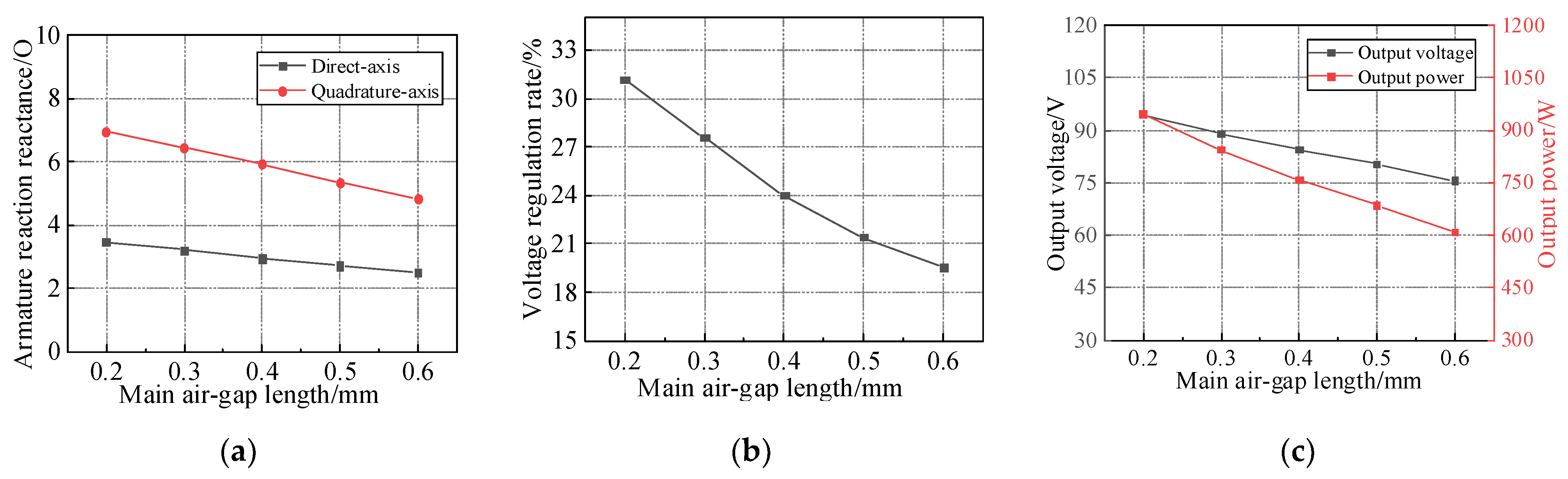
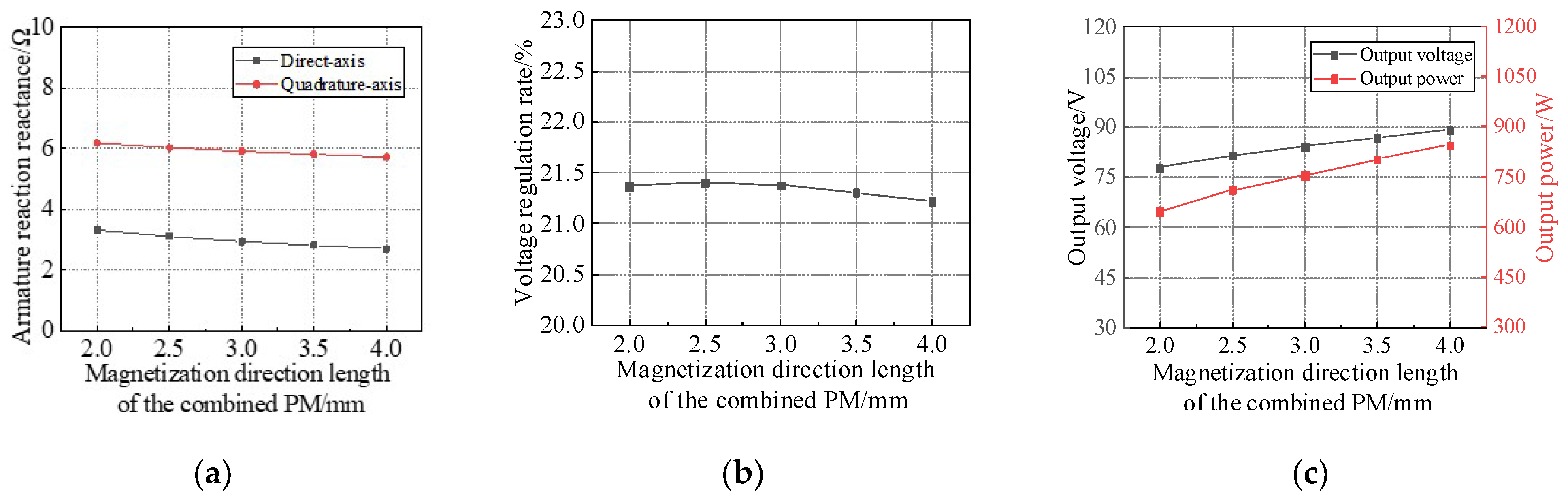
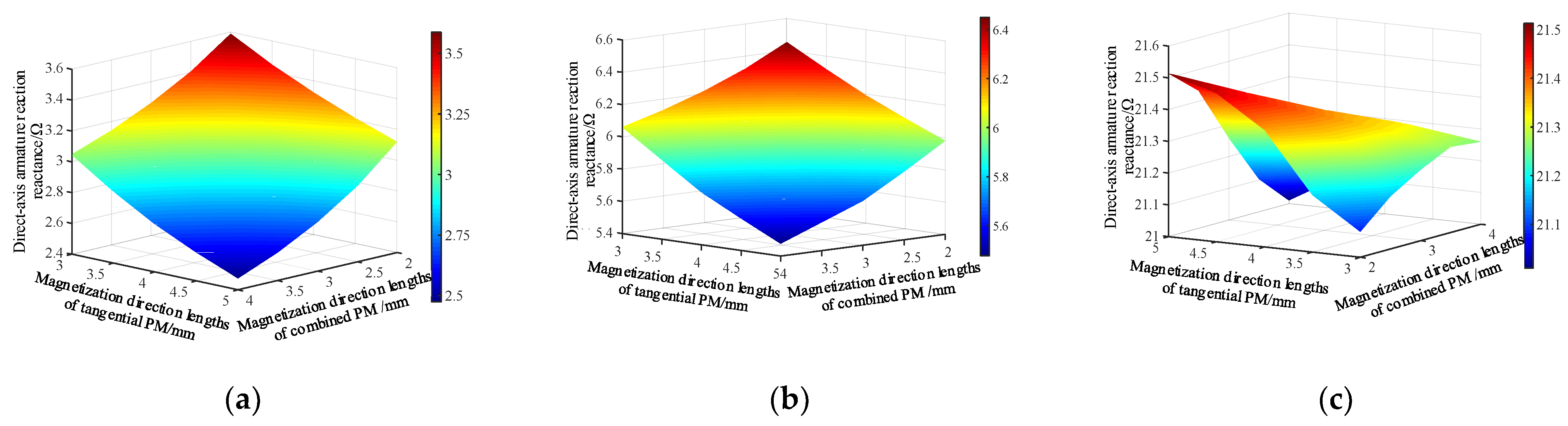
According to the analysis of the direct-axis and quadrature-axis ARMF, the main influencing factors of the direct-axis ARMF are the radial distance of the outer end of the tangential PM with smaller reluctance and the magnetization direction length of the tangential PM and the inner combined PM. The longer the radial distance of the outer end of the tangential PM, the smaller the magnetization direction length of the two PMs, the smaller the reluctance of the magnetic circuit of the direct-axis ARMF, and the larger the direct-axis armature reaction magnetic flux. The quadrature-axis ARMF mainly forms a magnetic circuit through the rotor core, and the rotor structure has little effect. Because it is mainly distributed on the outer circle of the rotor, the larger the distance between the outer end of the outer combined PM is, the smaller the influence of the quadrature-axis ARMF is. The larger the outer end distance of the tangential PM, the smaller the influence of the direct-axis ARMF on it. Meanwhile, the direct-axis and quadrature-axis ARMFs all pass through the main air gap and mainly act on the main air gap magnetic field. Increasing the main air gap reluctance can effectively increase the armature reaction magnetic circuit reluctance, thereby reducing the ARMF.

3. Optimization of Influence Parameters of Voltage Regulation Rate

Through the analysis of the influencing factors of the voltage regulation rate and armature reaction of the HESG, it can be obtained that the main influencing parameters are the armature winding turns, the length of the main air gap, the magnetization direction length of the tangential PM and the combined PM, and the length of the outer end of the tangential PM and the outer combined PM. Based on these influencing parameters, the finite element model of the HESG can be used to study their influence on the voltage regulation rate. To ensure the output requirements of the starter generator, the output voltage of the rated load condition under different influencing parameters is studied. Meanwhile, because the voltage regulation rate of the HESG ignores the influence of the electric excitation magnetic field, only the PM part is studied.

3.1. Armature Winding Turns

Under the rated speed and rated load conditions, the excitation current of the starter generator is set to 0.8 A, the length of the main air gap is fixed to 0.5 mm, and the magnetization direction lengths of the tangential PM and the combined PM are 5 mm and 3 mm, respectively. When the armature winding turns are changed to 5 turns, 6 turns, 7 turns, 8 turns, 9 turns, and 10 turns, the direct-axis and quadrature-axis armature reaction reactance, the voltage regulation rate, and the rated load output voltage and output power of the PM part are analyzed, and they are shown in Figure 7.
From Figure 7a, it can be seen that with the increase in the turns of the armature winding, the direct-axis and quadrature-axis reactance increase continuously, and the ARMF increases at this time. Figure 7b shows that with the increase in the turns of the armature winding, the voltage regulation rate increases almost linearly, so the armature winding turns should be taken as a smaller value. Figure 7c shows that with the increase in the armature winding turns, the flux linkage of each phase winding increases, the induced electromotive force increases, and the output voltage of the load condition increases. Meanwhile, with the increase in the armature winding turns, the output power of the starter generator increases. In this paper, the HESG is mainly based on the PM part, supplemented by the electric excitation part. The power of the PM part is 750 W. Therefore, the armature winding is designed to be eight turns. At this time, the output voltage under the rated load condition is 84.99 V, the output power of the PM part is 767.75 W, and the voltage regulation rate is 21.38%.

3.2. Main Air Gap Length

When the armature winding turns are fixed to eight turns, and the length of the main air gap of the starter generator is changed from 0.2 mm to 0.6 mm, the direct-axis and quadrature-axis armature reaction reactance, the voltage regulation rate, and the rated load output voltage and output power of the PM part are analyzed, and they are shown in Figure 8.
From Figure 8a,b, it can be seen that as the length of the main air gap increases, the direct-axis and quadrature-axis reactances decrease continuously. At this time, the armature magnetic field permeability decreases, the magnetic field weakens, and the voltage regulation rate decreases continuously. However, with the increase in the main air gap length, the reluctance of the rotor magnetic field increases, and the main magnetic field will be weakened, which will affect the electromagnetic output performance of the whole machine. As shown in Figure 8c, as the length of the main air gap increases, the output voltage and output power show a downward trend, the output efficiency decreases, and the output performance is weakened. To ensure effective output performance under rated conditions, the length of the main air gap in this paper is 0.4 mm. At this time, the output voltage of the starter generator is 84.47 V, and the output power is 758.42 W, which meets the design requirements.

3.3. Magnetization Direction Length of PM

When the main air gap is fixed to 0.4 mm, the influence of the magnetization direction length of the tangential PM and the combined PM on the electromagnetic performance of the starter generator is studied. When the magnetization direction length of the tangential PM is 3 mm, 3.5 mm, 4 mm, 4.5 mm, and 5 mm, the direct-axis and quadrature-axis armature reaction reactance, the voltage regulation rate, and the rated load output voltage and output power of the PM part are analyzed, and they are shown in Figure 9.
It can be seen from Figure 9a,b that with the increase in the magnetization direction length of the tangential PM, the quadrature-axis reactance gradually decreases, while the direct-axis reactance barely changes. The reason for this is that the tangential PM is designed in the quadrature-axis position of the rotor, and the change in the magnetization direction length directly impacts the quadrature-axis reactance. At the same time, with the increase in the magnetization direction length of the tangential PM, the voltage regulation rate shows a trend of slow rise and then slow decline. Figure 9c shows that with the increase in the magnetization direction length of the tangential PM, the output voltage and output power of the starter generator gradually increase. When the magnetization direction length is greater than 4 mm, the output voltage is greater than 84 V, and the output power is greater than 750 W under the rated load condition. Meanwhile, with the increase in the magnetization direction length of the tangential PM, the amount of PM increases rapidly, which will increase the manufacturing cost of the starter generator. Therefore, the magnetization direction length of the tangential PM in this paper is 4 mm.
When the main air gap is fixed to 0.4 mm, and the magnetization direction length of the combined PM is 2 mm, 2.5 mm, 3 mm, 3.5 mm, and 4 mm, the direct-axis and quadrature-axis armature reaction reactance, the voltage regulation rate, and the rated load output voltage and output power of the PM part are analyzed, and they are shown in Figure 10.
It can be seen from Figure 10 that as the magnetization direction length of the combined PM increases, the quadrature-axis reactance decreases gradually, the direct-axis reactance barely changes, and the voltage regulation rate decreases slowly. Figure 10c shows that with the increase in the magnetization direction length of the combined PM, the output voltage and output power of the starter generator increase. But the amount of PM also increases. When the magnetization direction length of the combined PM is 3 mm, the rated load output voltage equals 84.75 V, which meets the design requirements.
When the magnetization direction length of the tangential PM and the combined PM changes simultaneously, the changing surfaces of the armature reaction reactance and voltage regulation rate of the starter generator are analyzed, and they are shown in Figure 11.
Figure 11 shows that the smaller magnetization direction length of tangential PM and combined PM can obtain smaller quadrature-axis and direct-axis reactance, and vice versa. However, the smaller and larger values of the magnetization direction length of the tangential PM and the combined PM can obtain a lower voltage regulation rate, while the larger magnetization direction length of the tangential PM and the smaller magnetization direction length of the combined PM make the voltage regulation rate reach the maximum value. Therefore, the influence of the magnetization direction length of the tangential PM on the voltage regulation rate is greater than that of the magnetization direction length of the combined PM.
When the magnetization direction length of the tangential PM and the combined PM changes simultaneously, the change surfaces of output voltage and output power under rated load conditions are shown in Figure 12.
Figure 12 shows that the starter generator’s output voltage and output power increase almost linearly with the increase in the magnetization direction length of the two types of PM. The larger magnetization direction length of the tangential PM and the combined PM make the output voltage and output power reach the maximum. When the magnetization direction length of the tangential PM is greater than 4.5 mm, and the magnetization direction length of the combined PM is greater than 3 mm, the output voltage reaches 84 V, and the output power reaches 750 W. In this paper, the magnetization direction lengths of tangential PM and combined PM are 4.5 mm and 3 mm, respectively.
The above comparative analysis shows that the influence of armature winding turns and main air gap length on armature reaction reactance and voltage regulation rate is greater than that of PM parameters. In the analysis of PM parameters, the influence of tangential PM parameters on armature reaction reactance and the voltage regulation rate is greater than that of combined PM parameters.

4. Optimization Comparative Analysis and Performance Test

Through the optimization analysis, the influence parameters of the voltage regulation rate of the HESG before and after the optimization are obtained, as shown in Table 1.
The direct-axis and quadrature-axis armature reaction reactance, the voltage regulation rate, the rated load output voltage, and the rated load output power before and after parameter optimization are analyzed. The results are shown in Table 2.
Table 2 shows that the direct-axis and quadrature-axis armature reaction reactance and voltage regulation rate of the optimized starter generator are significantly reduced, and the optimized voltage regulation rate is 21.759%. Compared with before optimization, the rated load output voltage and output power of the optimized starter generator are slightly reduced. Still, it can meet the requirements of the output voltage and output power of the PM part.
At the same time, using the finite element software, the output power, various losses, and output efficiency can be obtained by fixing the excitation current and load and changing the speed of the starter generator. The variation curve of the output efficiency and speed of the starter generator is shown in Figure 13.
Figure 13 shows that when the excitation current and load are fixed, and the speed is between 2000 r/min and 4000 r/min, the output efficiency of the starter generator is basically unchanged. When the speed exceeds 4000 r/min, the output efficiency gradually decreases, and the overall output power remains at 88 % to 90 %. Based on the results, a prototype of HESG, with a rated power of 1 kW and a rated voltage of 84 V, is manufactured. The prototype mainly comprises a PM rotor, an electric excitation rotor, and a stator. The PM rotor and the electric excitation rotor are coaxial, side by side, and share the same stator. The main structural parameters of the starter generator are shown in Table 3.
The structure of the stator, rotor, whole machine of the HESG, and the test bench of the power generation condition are shown in Figure 14.

4.1. No-Load Characteristic Test under Power Generation Condition

Set the HESG speed to 4000 r/min, change the magnitude and direction of the excitation current, and test the output voltage under no-load conditions. The no-load characteristic curve of the HESG is obtained and shown in Figure 15.
Figure 15 shows that as the excitation current increases, the no-load output voltage of the starter generator gradually increases. When the excitation current changes from −1.5 A to 1.5 A, the no-load output voltage increases almost linearly, from 86.23 V to 112.78 V. When the excitation current is greater than 1.5 A or less than −1.5 A, the variation is no more linear. The regulation effect of the electric excitation magnetic field on the synthetic magnetic field is weakened. The experimental results show that the output voltage can be changed from 85.91 V to 113.54 V by changing the magnitude and direction of the excitation current, and the starter generator achieves a wide output voltage regulation range. Compared with the simulation results, the output voltage of different excitation currents obtained by the experiment is smaller. Still, the relative error is smaller, which verifies the accuracy of the finite element analysis results under no-load conditions.

4.2. Load Characteristic Test under Power Generation Condition

Set the starter generator speed to 4000 r/min, fix the excitation current at 0.8 A, change the load size, and test the output voltage of the starter generator. The external characteristic curve of the HESG is shown in Figure 16.
It can be seen from Figure 16 that when the starter generator is running at a fixed speed and a fixed excitation current condition, the output voltage of the starter generator decreases continuously with the increase in the load current. Because the pure resistive load is used to simulate the start generator load in the experiment, the external characteristic curve is almost a straight line. Meanwhile, the output voltages of different load currents obtained by the experiment are slightly smaller than the finite element simulation results, and the gap increases with the increase in the load current, but the error of the two methods is small. The experimental results also show that when the load current is 11.9 A and the excitation current is 0.8 A, the output voltage is 84.33 V, which meets the design requirements. When the excitation current is 0.8 A, it can ensure that the starter generator outputs stable voltage under rated conditions. When the load current is greater than the rated load current, the starter generator needs a larger excitation current to meet the output voltage requirements.

4.3. Magnetic Regulation Characteristics Test of Hybrid Excitation Starting Generator

Set the speed of the HESG to 4000 r/min, change the load size, and adjust the excitation current to ensure the stable output of the starter generator. The magnetic regulation characteristic curve is obtained and shown in Figure 17.
From Figure 17, the experimental results and finite element results of the magnetic regulation characteristics of the HESG are basically the same. However, when the load current is large and small, there is a small error in the results of the two methods. Meanwhile, with the load current increasing, the excitation current required by the starter generator continues to increase. When the load current increases from 3.57 A to 14.28 A, the excitation curve of the HESG is almost linear. When the load current increases or decreases, the slope of the excitation curve increases. At this time, increasing or reducing the load current requires greater forward or reverse excitation currents. It can also be seen from Figure 17 that when the load current is 16.07 A, the excitation current is 3.51 A, and the output power is 1350 W. Compared with the pure PM starter generator, the HESG can achieve a larger load current regulation range and bear a larger load.
When the load power of the starter generator is 980 W, 1000 W, and 1020 W, respectively, the voltage regulation performance test of the HESG is carried out from low speed to high speed. The test results are shown in Table 4.
According to Table 4, when the starter generator speed is 2000 r/min and the load power increases from 980 W to 1020 W, the maximum output voltage is 83.6 V and the minimum is 82.8 V, which is slightly lower than the rated voltage. When the speed is 4800 r/min, the output voltage under different load powers is about 84.6 V, slightly higher than the rated voltage. When the speed increases from 2000 r/min to 4800 r/min, and the load power increases from 980 W to 1020 W, the output voltage can be stable between 82.8 V and 84.6 V. It can be concluded that the starter generator voltage stabilizing controller can maintain the output voltage near the rated voltage under different speeds and load conditions. The starter generator has good voltage stabilizing performance.

5. Conclusions

In this paper, the influence of ARMF on the output performance of HESG is studied using the voltage regulation rate as the quantitative index. The analytical expression of the voltage regulation rate and the calculation method of armature reaction reactance are derived using the graphical method. The distribution of direct-axis and quadrature-axis ARMF of combined-pole PM magnetic field is simulated and analyzed using finite element software. The action law of armature reaction is given, and the main influencing parameters of the voltage regulation rate and armature reaction reactance are analyzed. Based on this, the influence of armature winding turns, main air gap length, and magnetization direction length of PM on armature reaction reactance, voltage regulation rate, and output power of the whole machine is studied, and the influencing parameters are optimized with the minimum voltage regulation rate as the goal while ensuring the output performance. The optimized comparative analysis shows that the direct-axis reactance, quadrature-axis armature reaction reactance, and voltage adjustment rate are significantly reduced, and the optimized voltage adjustment rate is 21.759%. Compared with the rated load output voltage and output power before and after optimization, it is slightly reduced, but it can meet the requirements of the PM part’s output voltage and output power. The prototype is manufactured and tested. The results show that when the speed and load are rated conditions and the excitation current is 0.8 A, the output voltage is 84.33 V, which meets the design requirements. Meanwhile, when the starter generator is in variable speed and load conditions, the voltage stabilizing controller can control the output voltage between 82.8 V and 84.6 V. The designed HESG shows good voltage stabilization performance.

Author Contributions

Conceptualization, M.G. and J.R.; methodology, M.G., W.H. and H.G.; software, W.H., Y.H. and S.Y.; validation, M.G., J.R. and H.G.; formal analysis, W.H., S.Y. and M.X.; investigation, Y.H. and M.X.; resources, M.G. and J.R.; data curation, M.G. and H.G.; writing—original draft preparation, M.G., J.R. and H.G.; writing—review and editing, M.G. and Y.H.; visualization, J.R., S.Y., and M.X.; supervision, M.G. and J.R.; project administration, W.H. and Y.H.; funding acquisition, W.H. and Y.H. All authors have read and agreed to the published version of the manuscript.

Funding

This research was funded by the National Natural Science Foundation of China, grant number 52275261, and the Natural Science Foundation of Shandong Province, grant number ZR2022QE116.

Data Availability Statement

The data presented in this study are available on request from the corresponding author. The data are not publicly available due to the confidential cooperation projects.

Conflicts of Interest

The authors declare no conflict of interest.

References

  1. Qin, S.F.; Xiong, Y.Q. Innovation strategies of Chinese new energy vehicle enterprises under the influence of non-financial policies: Effects, mechanisms and implications. Energy Policy 2022, 164, 112946. [Google Scholar] [CrossRef]
  2. Shannon, N. Preparing for the electric vehicle. Transm. Distrib. World 2022, 74, 56–57. [Google Scholar]
  3. Jose, S.S.; Chidambaram, R.K. Electric Vehicle Air Conditioning System and Its Optimization for Extended Range—A Review. World Electr. Veh. J. 2022, 13, 204. [Google Scholar] [CrossRef]
  4. Tran, M.-K.; Bhatti, A.; Vrolyk, R.; Wong, D.; Panchal, S.; Fowler, M.; Fraser, R. A Review of Range Extenders in Battery Electric Vehicles: Current Progress and Future Perspectives. World Electr. Veh. J. 2021, 12, 54. [Google Scholar] [CrossRef]
  5. Cheng, Z.; Xie, H.; Liu, C.; Li, C. Research on powertrain matching and control strategy of extended-range hybrid electric vehicle. In Proceedings of the 2020 IEEE International Conference on Information Technology, Big Data and Artificial Intelligence (ICIBA), Chongqing, China, 6–8 November 2020; pp. 1354–1358. [Google Scholar]
  6. Chen, Y.; Zhang, Y.; Wei, C.Y.; Li, G.; Li, C. Optimization of extended range electric vehicle energy management strategy via driving cycle identification. IOP Conf. Ser. Mater. Sci. Eng. 2020, 793, 012040. [Google Scholar] [CrossRef]
  7. Mao, S.; Han, M.; Han, X.; Shao, J.; Lu, Y.; Lu, L.; Ouyang, M. Analysis and Improvement Measures of Driving Range Attenuation of Electric Vehicles in Winter. World Electr. Veh. J. 2021, 12, 239. [Google Scholar] [CrossRef]
  8. Liu, H.; Lei, Y.; Fu, Y.; Li, X. An optimal slip ratio-based revised regenerative braking control strategy of range-extended electric vehicle. Energies 2020, 13, 1526. [Google Scholar] [CrossRef]
  9. Cipek, M.; Kasac, J.; Pavkovic, D.; Zorc, D. A novel cascade approach to control variables optimisation for advanced series-parallel hybrid electric vehicle power-train. Appl. Energy 2020, 276, 115488. [Google Scholar] [CrossRef]
  10. Yan, S.; Zhang, X.; Gao, Z.; Wang, A.; Zhang, Y.; Xu, M.; Hua, S. Design Optimization of a New Hybrid Excitation Drive Motor for New Energy Vehicles. World Electr. Veh. J. 2023, 14, 4. [Google Scholar] [CrossRef]
  11. Zhou, Z.; Hua, H.; Zhu, Z. Flux-Adjustable Permanent Magnet Machines in Traction Applications. World Electr. Veh. J. 2022, 13, 60. [Google Scholar] [CrossRef]
  12. He, X.; Bao, G. Suppression of Cross-Coupling Effect of Hybrid Permanent Magnet Synchronous Motor with Parallel Magnetic Circuit. World Electr. Veh. J. 2022, 13, 11. [Google Scholar] [CrossRef]
  13. Wang, H.; Wu, Z.; Liu, K.; Wei, J. Analysis and comparison of armature fields and inductances in various topologies of compulsators. IEEE Trans. Plasma Sci. 2020, 48, 4228–4234. [Google Scholar] [CrossRef]
  14. Zhu, J.; Li, G.H.; Cao, D.; Zhang, Z. Voltage regulation Rate and THD optimization analysis of coreless axial flux PM synchronous generator for wind power generation. IEEJ Trans. Electr. Electron. Eng. 2019, 14, 1485–1493. [Google Scholar]
  15. Chalmers, B.J. Performance of interior-type permanent magnet alternator. IEEE Proc. Electr. Power Appl. 1994, 141, 186–190. [Google Scholar] [CrossRef]
  16. Chalmers, B.J.; Akmese, R. Analysis of the voltage regulation characteristic of a permanent-magnet alternator with inverse saliency. Electr. Mach. Power Syst. 1997, 25, 317–326. [Google Scholar] [CrossRef]
  17. Chan, T.F.; Yan, L.T. Analysis and performance of a surface-mounted NdFeB permanent-magnet AC generator. APSCOM-97. Int. Conf. Adv. Power Syst. Control Oper. Manag. 1997, 2, 718–722. [Google Scholar]
  18. Chan, T.F.; Lai, L.L.; Yan, L.T. Performance of a three-phase AC generator with inset NdFeB permanent-magnet rotor. IEEE Trans. Energy Convers. 2004, 19, 88–94. [Google Scholar] [CrossRef]
  19. Chan, T.F.; Yan, L.T.; Lai, L.L. Performance of a permanent-magnet A.C. generator with rotor inverse saliency. In Proceedings of the Sixth International Conference on Electrical Machines and Systems, 2003. ICEMS 2003, Beijing, China, 9–11 November 2003; pp. 45–48. [Google Scholar]
  20. Abbas, A.; Iqbal, A. A subdomain model for armature reaction field and open-circuit field prediction in consequent pole permanent magnet machines. Int. J. Numer. Model. Electron. Netw. Devices Fields 2022, 35, e3023. [Google Scholar] [CrossRef]
  21. Morteza, M.B.; Faiz, J.; Khoshtarash, J. Impacts of number of poles and slots on armature reaction and performance of ironless permanent magnet motors. Electr. Power Compon. Syst. 2021, 48, 1979–1991. [Google Scholar]
  22. Li, H.R.; Lan, Z.Y.; Liao, K.L.; Wei, X.H.; Chen, L.H. Study on low voltage regulation rate of high power permanent magnet synchronous generator. Comput. Technol. Autom. 2016, 35, 51–55. (In Chinese) [Google Scholar]
  23. Wang, H.J.; Lan, B. Characteristic analysis of hybrid excitation permanent magnet synchronous generator. Micromotors 2011, 44, 33–36. (In Chinese) [Google Scholar]
  24. Wu, Q.; Xiong, H.; Liu, L.; Meng, G.; Li, H.; Zhou, L. Research on voltage regulation of a permanent magnet generator. In Proceedings of the 2011 International Conference on Electrical and Control Engineering (ICECE), Yichang, China, 16–18 September 2011; pp. 4935–4937. [Google Scholar]
  25. Guo, B.; Leng, Z.; Yang, Z.Y. Quantitative study on reducing measures of permanent magnet motor inherent voltage. Electr. Mach. Control Appl. 2012, 39, 16–19. (In Chinese) [Google Scholar]
  26. Cheng, Y.F. Single-Phase Hybrid Excitation Shaft Generator and Its Voltage Stability Characterise for Vehicle Loads; Harbin Institute of Technology: Harbin, China, 2010. (In Chinese) [Google Scholar]
  27. Fang, Y.; Ji, J.; Zhao, W. Modeling of Fault-tolerant Flux-switching Permanent-magnet Machines for Predicting Magnetic and Armature Reaction Fields. J. Electr. Mach. Syst. China Electrotech. Soc. 2022, 6, 413–421. [Google Scholar] [CrossRef]
  28. Abbaszadeh, K.; Rezaee, A.F. On-load field component separation in surface-mounted permanent-magnet motors using an improved conformal mapping method. IEEE Trans. Magn. 2016, 52, 1–12. [Google Scholar] [CrossRef]
  29. Ma, C.; Li, Q.; Lu, H.; Liu, Y.; Gao, H. Analytical model for armature reaction of outer rotor brushless permanent magnet DC motor. IET Electr. Power Appl. 2018, 12, 651–657. [Google Scholar] [CrossRef]
  30. Al-Adsani, A.S.; Beik, O. Characterization of a hybrid pm generator using a 32-phase brushless excitation scheme. IEEE Trans. Energy Convers. 2019, 34, 1391–1400. [Google Scholar] [CrossRef]
  31. Ghaffari, A. 2D Analytical Model of Armature Reaction Magnetic Field Distribution in Slotless Permanent-Magnet Linear Tubular Machines. J. Model. Optim. 2020, 12, 110–116. [Google Scholar] [CrossRef]
  32. Blanc, A. Exciting field and quadrature-axis armature reaction in a cascade equivalent A-H-circuit of a salient-pole generator. Int. J. Electr. Comput. Eng. 2020, 10, 1674–1681. [Google Scholar] [CrossRef]
  33. Tang, R. Theory and Design of Modern Permanent Magnet Motors, 6th ed.; China Machine Press: Beijing, China, 2015. [Google Scholar]
Figure 1. Structure diagram of the hybrid excitation starter generator (HESG).
Wevj 14 00286 g001
Figure 2. Relationship between armature reaction magnetomotive force and rotor magnetomotive force: (a) pure resistive load condition; (b) pure inductive load condition; (c) pure capacitive load condition.
Wevj 14 00286 g002
Figure 3. Vector diagram of starter generator under resistance inductive load condition.
Wevj 14 00286 g003
Figure 4. Stator slot and armature winding parameters.
Wevj 14 00286 g004
Figure 5. The vector diagram of the equivalent direct-axis and the equivalent quadrature-axis states: (a) equivalent direct-axis state; (b) equivalent quadrature-axis state.
Wevj 14 00286 g005
Figure 6. The magnetic field line distribution diagram and magnetic density cloud diagram of armature reaction magnetic field (ARMF) in two states: (a) direct-axis magnetic field line diagram; (b) direct-axis magnetic density cloud diagram; (c) quadrature-axis magnetic field line diagram; (d) quadrature-axis magnetic density cloud diagram.
Wevj 14 00286 g006
Figure 7. Electromagnetic characteristic parameters of starter generator with different armature winding turns: (a) direct-axis and quadrature-axis armature reaction reactance; (b) voltage regulation rate; (c) output voltage and output power.
Wevj 14 00286 g007
Figure 8. Electromagnetic characteristic parameters of starter generator with different lengths of main air gap: (a) direct-axis and quadrature-axis armature reaction reactance; (b) voltage regulation rate; (c) output voltage and output power.
Wevj 14 00286 g008
Figure 9. Electromagnetic characteristic parameters of starter generator with different magnetization direction lengths of tangential permanent magnet (PM): (a) direct-axis and quadrature-axis armature reaction reactance; (b) voltage regulation rate; (c) output voltage and output power.
Wevj 14 00286 g009
Figure 10. Electromagnetic characteristic parameters of starter generator with different magnetization direction lengths of combined PM: (a) direct-axis and quadrature-axis armature reaction reactance; (b) voltage regulation rate; (c) output voltage and output power.
Wevj 14 00286 g010
Figure 11. Surface diagram of direct-axis and quadrature-axis armature reaction reactances and the voltage regulation rate with different magnetization direction lengths of PM: (a) direct-axis armature reaction reactance; (b) quadrature-axis armature reaction reactance; (c) voltage regulation rate.
Wevj 14 00286 g011
Figure 12. Surface diagram of output voltage and output power under rated load conditions with different magnetization direction lengths of PM: (a) output voltage; (b) output power.
Wevj 14 00286 g012
Figure 13. Starter generator output efficiency curve.
Wevj 14 00286 g013
Figure 14. Pictures of the HESG and the test bench: (a) PM rotor; (b) electric excitation rotor; (c) stator; (d) parallel combined rotor; (e) prototype; (f) generating condition experimental platform.
Wevj 14 00286 g014
Figure 15. No-load characteristic curve of HESG.
Wevj 14 00286 g015
Figure 16. External characteristic curve of HESG.
Wevj 14 00286 g016
Figure 17. Magnetic characteristic curve of HESG.
Wevj 14 00286 g017
Table 1. Influence parameters of the voltage regulation rate before and after the optimization.
Parameter NameBefore OptimizationAfter Optimization
Armature winding turns9 turns8 turns
Main air gap length0.5 mm0.4 mm
Magnetization direction lengths of tangential PM5 mm4.5 mm
Magnetization direction lengths of combined PM2.5 mm3 mm
Table 2. Output performance comparison of HESG before and after parameter optimization.
Parameter NameBefore OptimizationAfter Optimization
Direct-axis reactance/Ω3.4033.117
Quadrature-axis reactance/Ω6.6606.029
Voltage regulation rate/%28.14521.759
Rated load output voltage/V84.36984.341
Rated load output power/W756.604756.10
Table 3. Main structural parameters of the starter generator.
Parameter NameParameter Value
Stator outer diameter140
Stator inner diameter106
Axial length of the stator43
Main air gap length0.4
Rotor outer diameter105.2
Magnetization direction length of tangential PM4.5
Length of tangential PM15
Magnetization direction length of combined PM12
Length of combined PM3
Thickness of pole boots1.7
Axial length of the PM rotor20
Axial length of the claw-pole rotor20
Flange thickness of the claw-pole rotor9
Yoke thickness of the claw-pole rotor16
Claw root thickness9
Claw tip thickness2.7
Pole arc coefficient of claw root1.05
Pole arc coefficient of claw tip0.45
Table 4. Voltage stabilizing performance test results of HESG.
Speed/(r/min)Load Power/WOutput Voltage/V
200098083.6
100083.1
102082.8
400098084.4
100084.3
102084.2
480098084.6
100084.6
102084.5
98083.6
Disclaimer/Publisher’s Note: The statements, opinions and data contained in all publications are solely those of the individual author(s) and contributor(s) and not of MDPI and/or the editor(s). MDPI and/or the editor(s) disclaim responsibility for any injury to people or property resulting from any ideas, methods, instructions or products referred to in the content.

