Article

Functional Model of an Automatic Vehicle Hold Based on an Electro-Hydraulic Braking System

School of Mechanical and Automotive Engineering, Shanghai University of Engineering Science, Shanghai 201620, China
*
Authors to whom correspondence should be addressed.
World Electr. Veh. J. 2023, 14(10), 277; https://doi.org/10.3390/wevj14100277
Submission received: 28 August 2023 / Revised: 4 September 2023 / Accepted: 12 September 2023 / Published: 2 October 2023

Abstract

:
The algorithm function designed in this paper can make a car maintain stability during automatic vehicle hold through the model input of multi-level target fluid pressure combined with slope judgment modules of different levels after the automatic vehicle hold software works. At the same time, a complete parking function module is designed, which can monitor the whole parking process in real time. Through the design of this function, the functional diversity of the electro-hydraulic braking system can be increased. When judging that the driver intends to start, the automatic vehicle hold system will automatically release the fluid pressure according to the opening of the accelerator pedal pressed by the driver so that the vehicle does not happen to brake when the vehicle starts in the slippery slope condition. Finally, real vehicle verification proves that the function can effectively meet the parking requirements and start on the flat and on a ramp. Also, it can effectively control the vehicle according to the driver’s driving intention.

1. Introduction

Today’s automotive industry is gradually getting onboard with the trend for new energy. Automotive braking has also undergone a considerable change. As the traditional vacuum booster slowly withdraws from the automotive braking, the new integrated electro-hydraulic braking system, with its excellent performance and good compatibility [1,2], is increasingly present in the assembly of new energy vehicles. At the same time, significant changes have been made to the automotive braking in some of the auxiliary functions of the car, through the improvement of the braking functional diversity and parking stability, the electro-hydraulic braking system is in line with the development trend of modern automotive parts: lightweight and intelligent.
EHB is the abbreviation of the Electro-Hydraulic Brake System (EHB), which has the advantages of adjustable braking feeling, active pressure build-up, fast response speed, precise hydraulic pressure control [3], and high braking energy recovery rate. Due to the development of electro-hydraulic braking technology [4], there will be more and more assisted driving functions based on braking, such as comfortable parking functions, steep hill descent functions, and emergency braking functions. As a new type of product in the braking industry, EHB will have significant advantages in the future in the country’s and even in the world’s electric vehicles, and the future market will be broad [5]. The composition of the electro-hydraulic braking system is shown in Figure 1 [6].
In some scenarios, the driver parking the car has a relatively high-frequency demand on the automatic vehicle hold (AVH) function. This function reduces the need for the driver to step on the brake pedal for a long time [7]. The AVH function is on when the driver steps on the brake pedal to stop the vehicle, allowing the driver to release the brake pedal. The electro-hydraulic braking system can maintain a certain amount of braking force to keep the vehicle stationary [8].
The autohold vehicle system proposed by Lv Chang presents a concrete structure for the novel auto-hold system of hydrostatic transmission wheeled vehicles and deeply analyses the working mechanism and control method [9]. Some scholars put forward the idea of using a ramp start to replace automatic parking. However, based on the fact that most of the auxiliary functions of a ramp start can only maintain 2–3 s and then release the fluid pressure without detecting whether the accelerator pedal is pressed, although the foot movement time from the brake pedal to the accelerator pedal can be met, it cannot meet all the needs of the driver.
This paper focuses on the design of an automatic vehicle hold software, which can modify the target fluid pressure and target slope of multiple levels to meet stable parking on the flat and slope, which not only meets the driving needs of drivers but also can modify parameters through software rewriting alone to meet the needs of all kinds of vehicles.

2. Automatic Vehicle Hold Function Design Based on the Electro-Hydraulic Braking System

2.1. Electro-Hydraulic Brake System Function

The braking principle of the electro-hydraulic braking system is as follows: when the brake pedal is pressed down [10,11], the pedal will push the actuator to move at the same time, and the pedal displacement sensor integrated into the brake pedal is inputted into the controller of the electro-hydraulic braking system according to the displacement signal of the pedal movement [12]. When receiving the signal from the displacement sensor, according to the driver’s intention to brake, the controller carries out a specific rotation through the system’s motor, which drives the worm gear movement. The worm gear drives the gears and racks to raise the piston of the master cylinder, the brake fluid from the master cylinder goes through the pipeline into the wheel cylinder, which is then clamps to generate braking force, inducing the tire braking [13], to complete the process of a pressure building [14].

2.2. Automatic Vehicle Hold Function Introduction

The EHB system receives signal commands from the vehicle bus and writes its controller into the software using algorithms [15], which can control the target hydraulic pressure for different application scenarios. As an auxiliary function of the vehicle, the EHB determines whether the auto parking condition is reached according to the wheel speed signal after the auto parking function is enabled. The gradient sensor calculates the current parking gradient and outputs the corresponding parking hydraulic pressure according to the angles [16]. When the driver wants to move the vehicle with the accelerator pedal, the auto parking function will judge whether the hydraulic pressure releases or not based on the accelerator pedal’s opening threshold and the motor torque threshold parameter, which can be calibrated to different gradients and can be used for the control of hydraulic pressure. When the driver wants to move the vehicle with the accelerator pedal, the auto park function will judge whether the hydraulic pressure releases according to the accelerator pedal opening threshold and the motor torque threshold parameter.

2.3. Automatic Vehicle Hold Software Functions

The point of how the auto park function works is that the software function will take over parking when the driver presses the auto park button. When it is necessary to start, the AVH system will provide the hydraulic pressure and pressure release according to the driver’s demand [17,18]. In this paper, the function will be modularly modelled and designed using Matlab/Simulink software (R2018b), and all the modules will be integrated and burned into the controller of the EHB after C code generation.
The function consists of modules, such as the enabling judgement unit module, target fluid pressure calculation module, and parking function module. The software contains input and output signals.

2.4. Target Fluid Pressure Calculation Module

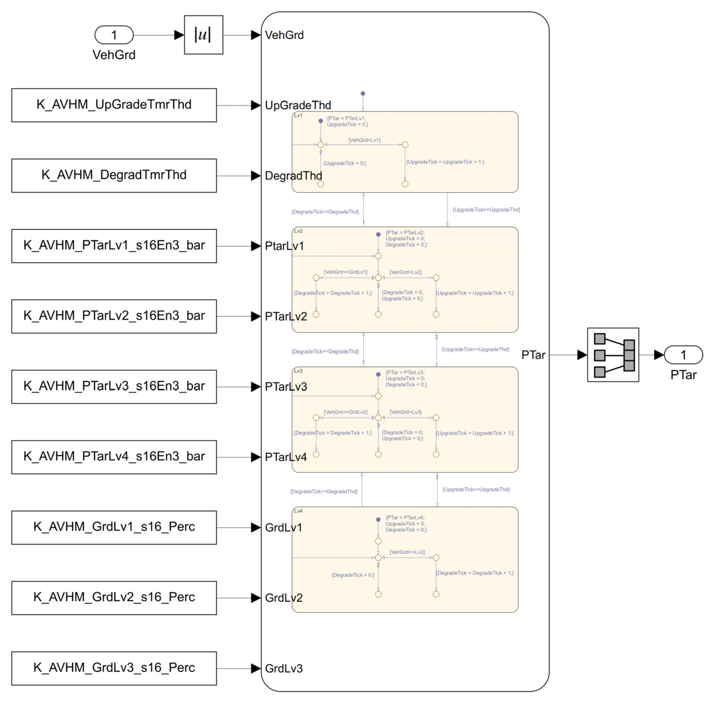
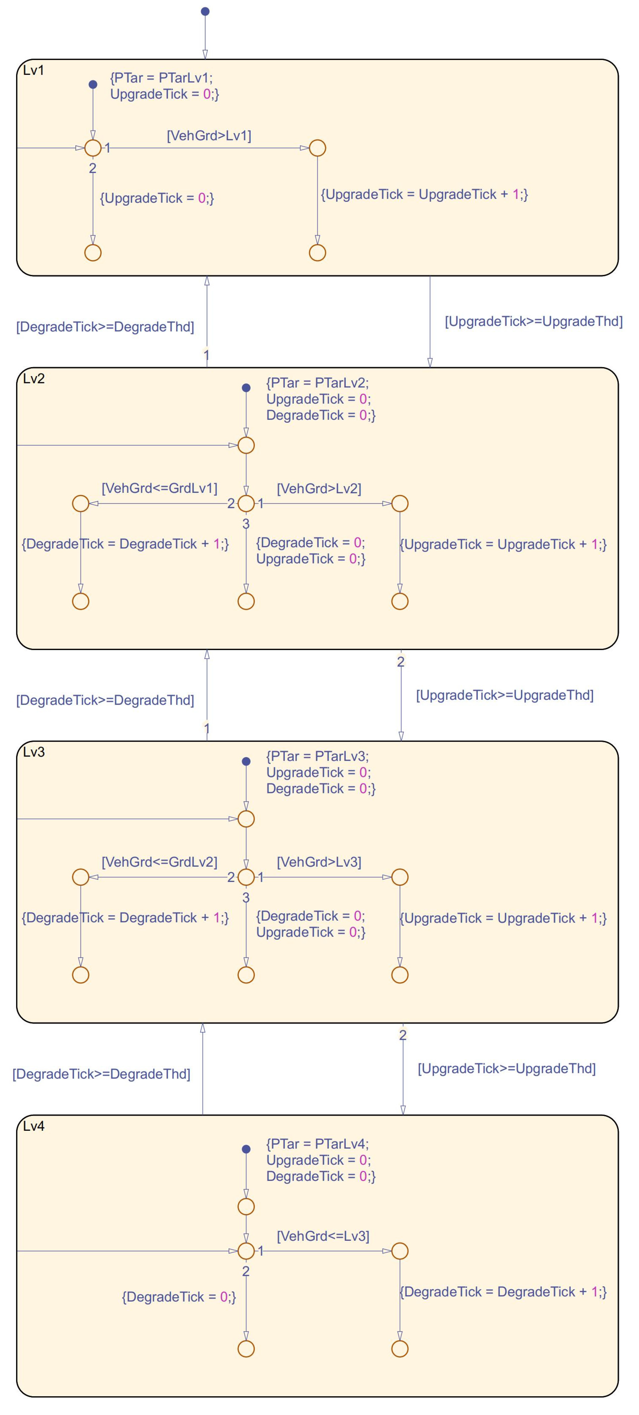
The target hydraulic pressure calculation module is the core of the AVH function in the software design. This functional unit calculates the parked hydraulic pressure while judging whether to park or not according to the gradient of the vehicle [19], the gradient rise and fall thresholds, the pre-set hydraulic pressure size of the various grades that need to be kept under pressure, as well as the different grades of the vehicle’s gradient [20]. The drawings which show external and internal diagrams of the calculation module are shown in Figure 2 and Figure 3.
The module unit design logic is structured according to the size of the slope at different levels; in the output of the level corresponding to the parking fluid pressure, when found that the throttle opening degree is 0 and there is a demand for the automatic vehicle hold function, the functional unit will determine the parking demand for fluid pressure based on the vehicle in the slope.
The hydraulic pressure level is pre-set to four levels, the gradient level to three, and the rising and falling thresholds set simultaneously. By comparing the input vehicle gradient, the target hydraulic pressure level will be set to PTarLv1 at the beginning, and when Vehgrd is greater than GrdLv1 the Upgrade Tick will be increased by one, and it will then be compared with the rising threshold value, UpgradeThd. However, if it is still greater than or equal to GrdLv1, then it will enter the Lv2 frame with the target hydraulic pressure level set to PTarLv2, and at the same time the vehicle gradient VehGrd and GrdLv2 size comparison will continue. If VehGrd is less than GrdLv2, then it will return to the Lv1 frame. If it is still greater than then it will enter the Lv3 frame; similarly, it will enter the Lv4 frame when the vehicle locates a gradient that is not less than the Lv3 level of the resident slope. Hydraulic pressure will be a more considerable fluid pressure at the pressure level PTarLv4; if the grade of the ramp is less than Lv3 then it will retreat to the previous grade frame.
The hydraulic pressure can be based on the performance of a specific actual vehicle on the ramp, the threshold value for modification and calibration, while the parameters of PTarLv1, PTarLv2, PTarLv3, PTarLv4, GrdLv1, GrdLv2, and GrdLv3 can be adjusted until they meet the vehicle’s demand. The hydraulic pressure can be regulated in real time according to this logic so that the vehicle can maintain the required parking hydraulic pressure when the angle of the ramp changes.
According to the design of the Matlab/Simulink model used to collate the logic block diagram to facilitate the understanding and analysis of the overall architecture, the later modules—in order to facilitate the reading and understanding of the logic block diagram—will be in the form of the exhibition.

2.5. Parking Function Unit Module

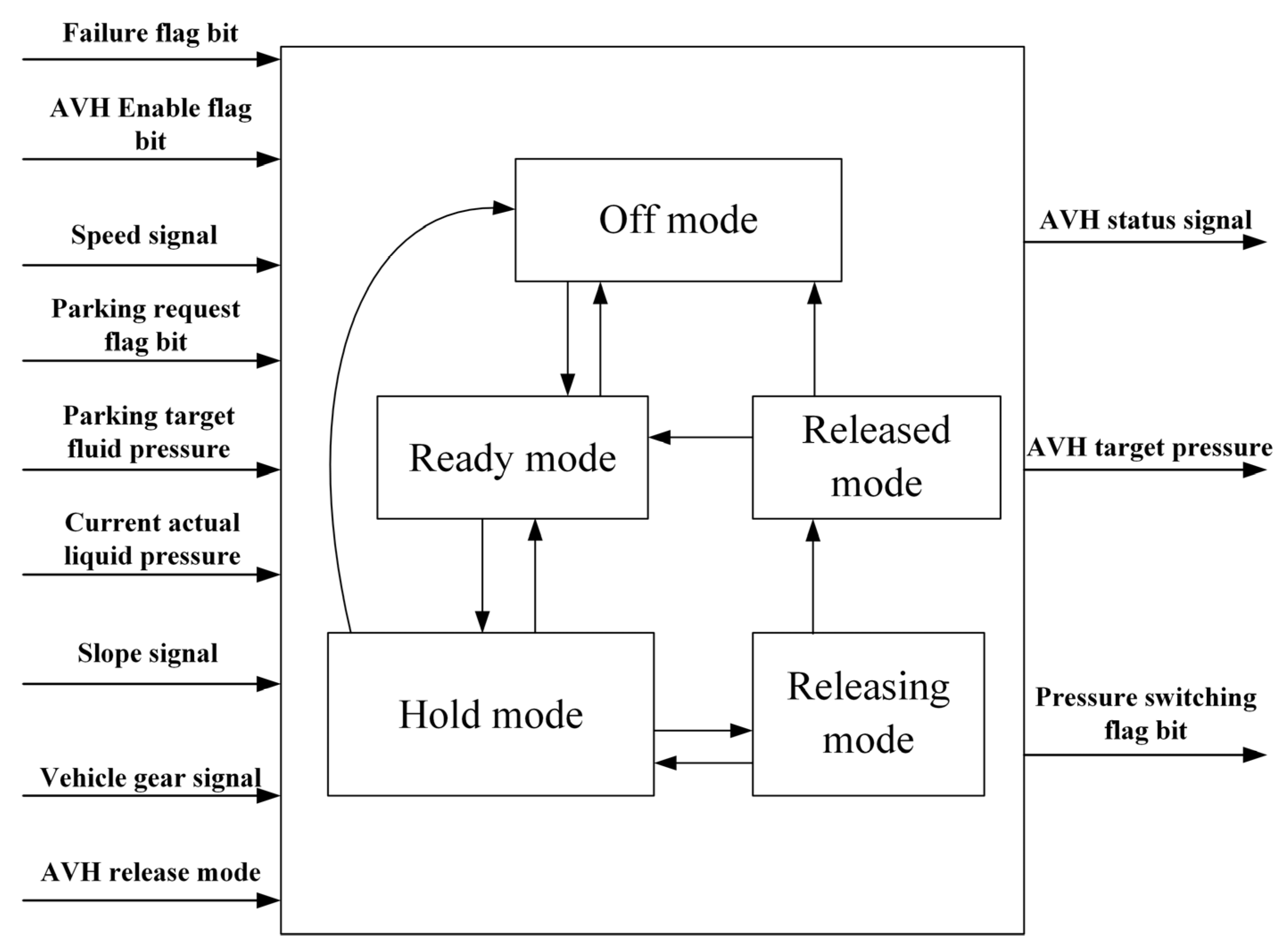
The specific logic of this function unit is as follows: when the AVH function does not request parking, the output pressure switching flag bit value issued is the initial value and the parking target fluid pressure is inputted from the brake pedal, used as the output target fluid pressure.
When the AVH function is enabled and the AVH satisfies the ready state, the AVH release mode signal shows that the vehicle is already in the state of requesting parking. When the AVH function is enabled and the AVH function meets the ready state, it means the failure flag bit signal does not issue an invalid value. At the same time, the AVH release mode signal shows that the brake fluid pressure meets the regular release, and the parking request flag bit will show that the vehicle is in the state of requesting to park when the vehicle’s current gear is not in the P gear. This time, the AVH function can meet the state of pressure preservation.
If the target hydraulic pressure of the AVH function is less than the current hydraulic pressure from the pedal, then the hydraulic pressure value inputted from the brake pedal will be used as the output AVH target pressure; when the target hydraulic pressure of AVH is greater than the target hydraulic pressure inputted from the pedal, then the calculation module will use the PTar of the output AVH function as the output hydraulic pressure value.
When the difference between the calculated output hydraulic pressure and the actual hydraulic pressure is greater than 5 bar, the AVH function will re-calculate the hydraulic pressure demand. When it exceeds the internal time threshold of the system, it will use the maximum hydraulic pressure value of the calculation module at the same time to prevent skidding.
When the pressure switching flag bit signals switching, it means that the driver intends to start, and the AVH function will enter the release mode. The hydraulic pressure gradually releases at this time, and the pressure switching flag bit signal changes to 0. The target hydraulic pressure inputted from the brake pedal will be used as the hydraulic pressure outputted from the AVH function, and when the absolute value of the difference between the target hydraulic pressure of the AVH function and the brake hydraulic pressure of the actual brake pedal pushed down is confirmed to be smaller than 3 bar, at this time the AVH function will re-calculate the hydraulic pressure demand to 3 bar, so that the status of the AVH function is release complete.
When the function is carried out under this module, the AVH status signal, AVH target fluid pressure signal, and fluid pressure switching flag signal are finally output. It is used to monitor the vehicle status during the parking process. The logic block diagram is shown in Figure 4.

3. Park and Start Analysis

3.1. Dynamic Analysis of the Automatic Vehicle Hold Function

The analysis and its modelling are carried out by creating a dynamic model of a vehicle travelling on a ramp on a horizontal road surface [21,22], simulating the forces on the vehicle during acceleration and braking on the ramp.
The Figure 5 shows that the forces on the vehicle on the ramp are driving force F t , rolling resistance F f , air resistance F w , ramp resistance F i , acceleration resistance F j , and braking force F b . The mechanical relationship is shown in Equation (1):
F t + F b = F f + F w + F i
Each force relationship can simultaneously be written as Equation (2) [23]:
T m i 0 η r + β T u max r = G f cos γ + C D A v 2 21.15 + G sin γ + δ m d v d t
where T m is the motor driving torque, i 0 is the overall gear ratio, η is the mechanical efficiency of the drive line, r is the wheel radius, G is the gravitational force acting on the car, f is the rolling resistance coefficient, C D is the coefficient of air resistance, A is the windward area, v is the car speed, γ is the ramp angle, δ is the car’s rotating mass conversion coefficient, d v / d t is the travelling acceleration, m is the car’s weight, T u m a x is the maximum braking torque, and β is the brake pedal opening degree.

3.2. The Variation of Forces during the Starting Process

When the vehicle just starts, we can consider that the acceleration resistance at this time is 0, while the effect of air resistance can be ignored. So the forces on the vehicle at this time are the driving force F t , rolling resistance F f , ramp resistance F i and braking force F b , the variation of force at each stage of automatic vehicle hold is shown in Figure 6. The green line is driving force, and the red line is braking force, the blue line is the sum of rolling resistance and ramp resistance.
0 to P1: When the electro-hydraulic braking system provides brake fluid pressure to prevent the vehicle from skidding according to the current road gradient size fed back by the gradient sensor [24], the torque output from the motor is zero when the vehicle is stationary and not started at the ramp. That is, as shown in Equations (3) and (4):
F t = 0
F b F i + F f
P1 to P2: When the driver presses the accelerator pedal, the output torque of the motor increases, and the brake fluid pressure decreases along with the increase of the driving force of the motor, but at this time, when the driving force on the wheels related to the torque of the drive motor cannot overcome the resistance of the ramp, in order to prevent slippery slopes, the force provided by the drive motor and the brake fluid pressure needs to be greater than the resistance of the ramp [25,26]. That is, as shown in Equation (5):
F t + F b > F i + F f
When the driving force on the wheels related to torque of the drive motor is equal to overcoming the resistance of the vehicle on the ramp, as shown in Equation (6):
F t = F i + F f
P2: at this point, when the driving force is not enough to drive the vehicle forward, brake fluid pressure is required to prevent vehicle skidding that occurs at the critical point.
P2 to P3: when the accelerator pedal continues to be depressed, the motor output torque is high enough at this point, as shown in Equation (7):
F t > F i + F j + F f
At this point, the vehicle can overcome the resistance of the ramp to allow a smooth start, and the hydraulics pressure can be gradually and wholly released.
For vehicles equipped with an electro-hydraulic braking system, in the instance where the driver does not need to operate the vehicle brake system, the automatic vehicle hold function can complete the process of parking and starting according to the ramp information transmitted via the sensor [27], combined with the driver’s parking and start intention. When the vehicle is to be stationary on the ramp, the force is applied as shown in Equation (8):
F t + F b F f + F i

3.3. Automatic Vehicle Hold Control Strategy for the Electro-Hydraulic Brake System

The control strategy as well as the block diagram of the algorithm for the electro-hydraulic braking system is shown in Figure 7.
Stage 1: The EHB obtains whether the road surface on which the vehicle is currently located is a ramp section according to the slope sensor. If it is on a ramp, the EHB will calculate the amount of brake fluid pressure needed in the current state to prevent the vehicle from skidding when parking and starting; if it is on a flat surface, the fluid pressure will be maintained at a pre-set lower level (around 10 bar) to enable the vehicle to be parked stably, and at the same time gradually released to 0 to meet the starting demand when starting.
Stage 2: When the driver has the intention to start at the end of the parking, when the accelerator pedal is pressed down the motor outputs torque Ft. At this time, the EHB reduces the maintained hydraulic pressure according to the output of the motor, and at the same time, according to whether or not the output of the motor is greater than the downward moment of the ramp. If it is greater than that, then the EHB reduces the hydraulic pressure to zero, and the vehicle starts up smoothly.
Stage 3: If the motor output torque is not enough to start the vehicle, the EHB still provides brake fluid pressure to ensure that the braking force and the motor output torque should always be greater than the downhill movement of the vehicle. Otherwise, it will lead to a downhill situation. When the motor output has been increasing, EHB reduces the brake fluid pressure provided until the motor output torque is greater than the resisting torque of the vehicle sliding down, and the hydraulic control fluid pressure reduces to 0 to ensure the vehicle starts.

4. Real Vehicle Tests

The AVH model constructed in this paper is used to generate C code via Simulink software (R2018b), and the integrated software in the S19 format generates code through the compilation process.
The software is burned into the controller of the EHB through the OBD interface of the whole vehicle via the host computer and PCAN line, which is used to verify whether the software can effectively make the car park and start smoothly, and at the same time, to carry out the observation of the effect of the road test. The equipment needed for the actual vehicle test includes the OBD cable (responsible for the connection node between the vehicle and the external communication), PCAN cable (used for the data channel connection between the computer and the vehicle network), and the laptop (used for the calibration of the parameters in the software, turning on or off the relevant function flags, and recording and replaying the driving parameters).
In this paper, the test vehicle is a battery electric vehicle used to verify the software’s function—the vehicle’s specific parameters are shown in Table 1.

4.1. Automotive Vehicle Hold Function Verified without Slope Condition

By verifying the automatic vehicle hold function of the whole vehicle on a relatively flat road, the AVH model can observe the vehicle speed, hydraulic pressure, accelerator pedal opening, brake pedal status and other signals to observe the state of the vehicle in the functional operation. It can also analyse the data to make corresponding improvements. The experiment is as follows:
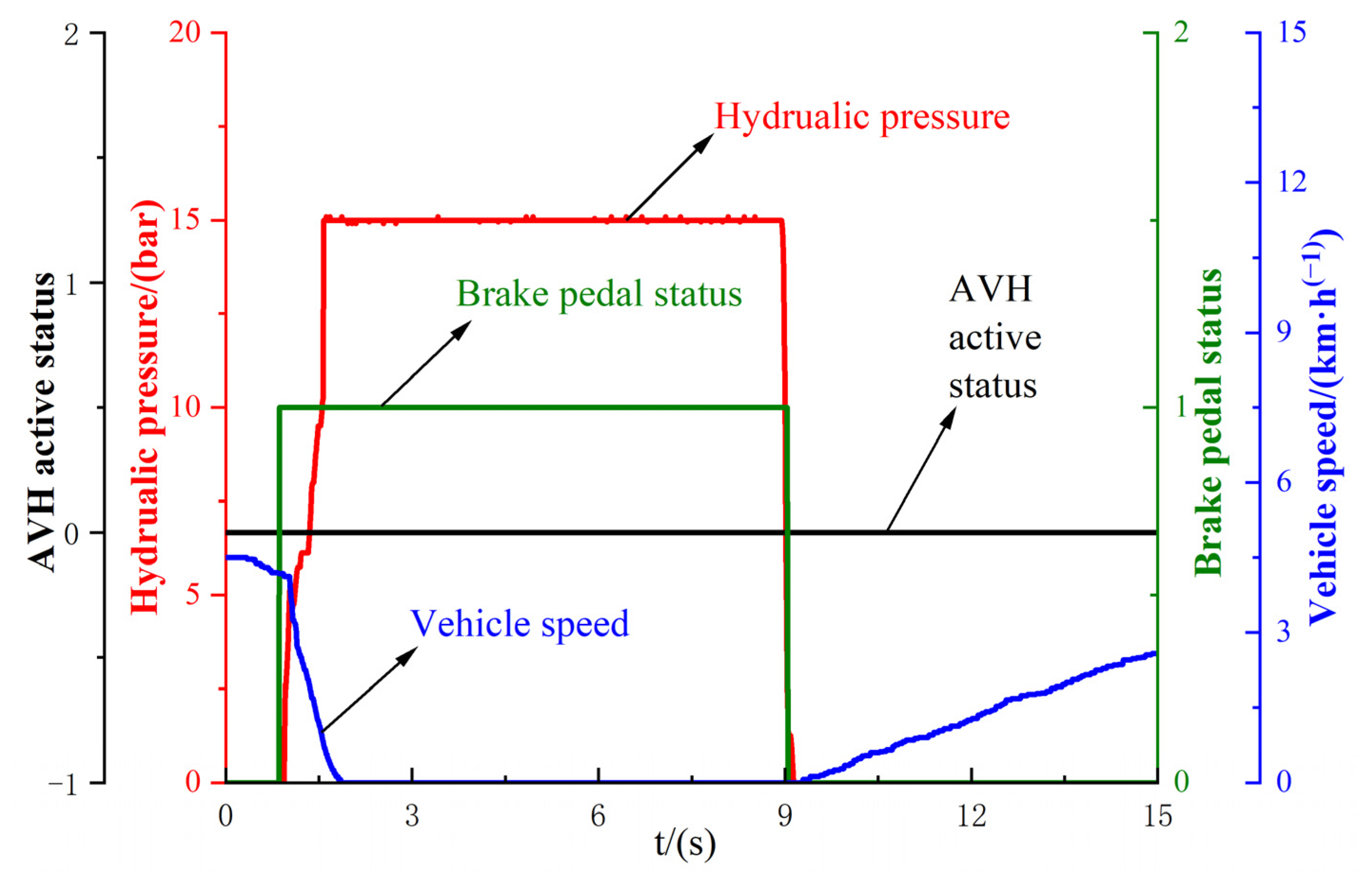
Firstly, verify the vehicle braking status when AVH is not enabled, as shown in Figure 8.
When the AVH function is not enabled, and the car brake pedal is pressed, the brake pedal status changes from 0 to 1, the fluid pressure rises, and, at this time, the vehicle speed reduces to 0. When the brake pedal is pressed, the vehicle does not move. When the brake pedal lowers, the car does not move under the action of no brake fluid pressure because the gear is in D, simulating the fuel car idling mode; the torque of the drive motor is not zero but idles so the speed of the car changes. Without braking force and without taking the protective measures of shifting gears or pulling up the electronic handbrake, the vehicle moved.
As shown in Figure 9, the vehicle in the accelerator pedal opening and drive motor torque response and feedback also matches the state of the vehicle’s acceleration, and at the same time, in the absence of the accelerator pedal being pressed due to the setting of the idling mode, the drive motor torque is not zero, which meets the needs of the vehicle test.
When the AVH function is switched on, the vehicle brakes again to monitor whether the automatic vehicle hold function could help the driver with parking needs. The experiment is as follows (Figure 10).
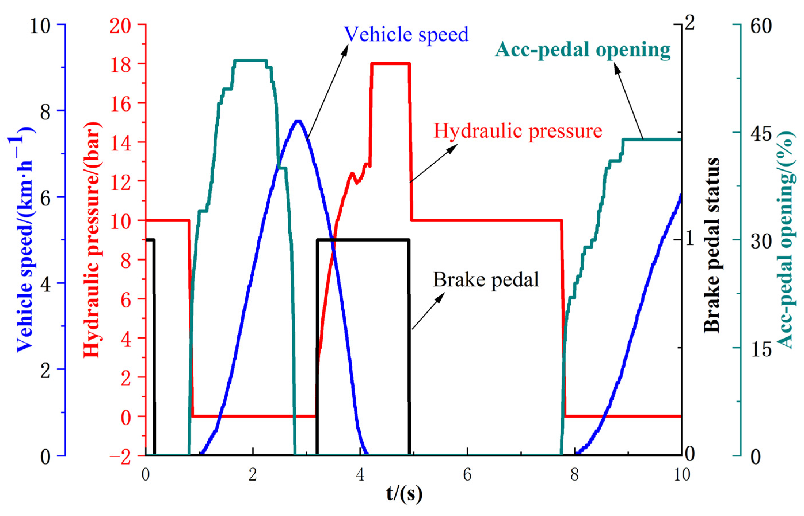
Figure 10 shows that with the software function enabled on level ground, at 0–1 s, the brake pedal status signal goes from 1 to 0, indicating the process of the pedal going from depressed to lowered; hydraulic pressure decreases with the increase of the throttle opening when it considers that the vehicle has the intention to start. At 1–3 s, the vehicle speed reaches a maximum of 8 km/h through the change of the level of the accelerator pedal pressed. At 3–5 s, the hydraulic pressure rises by depressing the brake pedal, and the vehicle speed decreases to zero. During 5–8 s, the brake pedal status is always 0, which means the brake pedal did not press. The fluid pressure maintains 10 bar, and the vehicle speed maintains 0. At this time, it can be seen that the automatic vehicle hold function can help the driver maintain the parking status through the software.

4.2. Validation of the Automatic Vehicle Hold Function under Ramp Conditions

After verifying that the vehicle can carry out the automatic vehicle hold function in the no-slope condition, this time, to verify whether the automatic vehicle hold function on the ramp can complete the same parking action, based on the hydraulic force required on different slopes to maintain pressure to achieve the automatic vehicle hold function, the experiment is shown in Figure 11 and Figure 12.
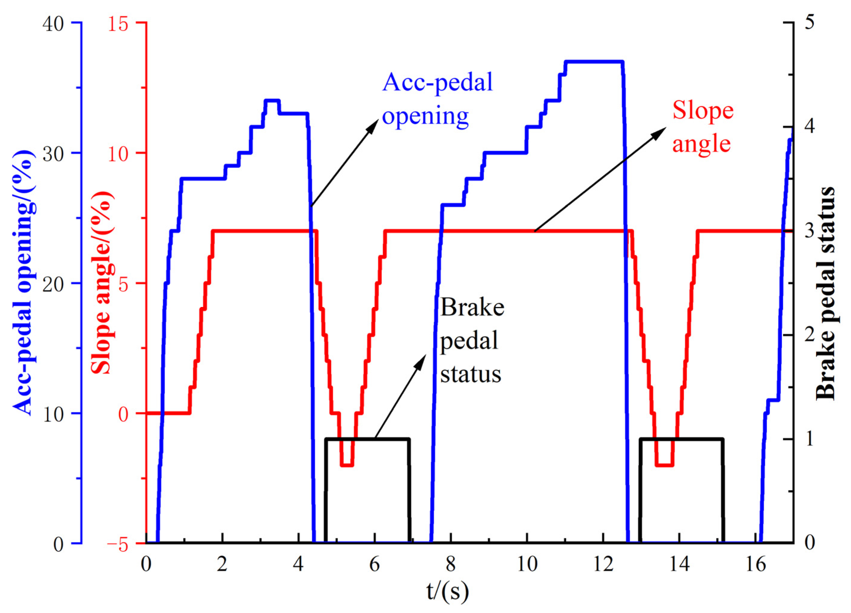
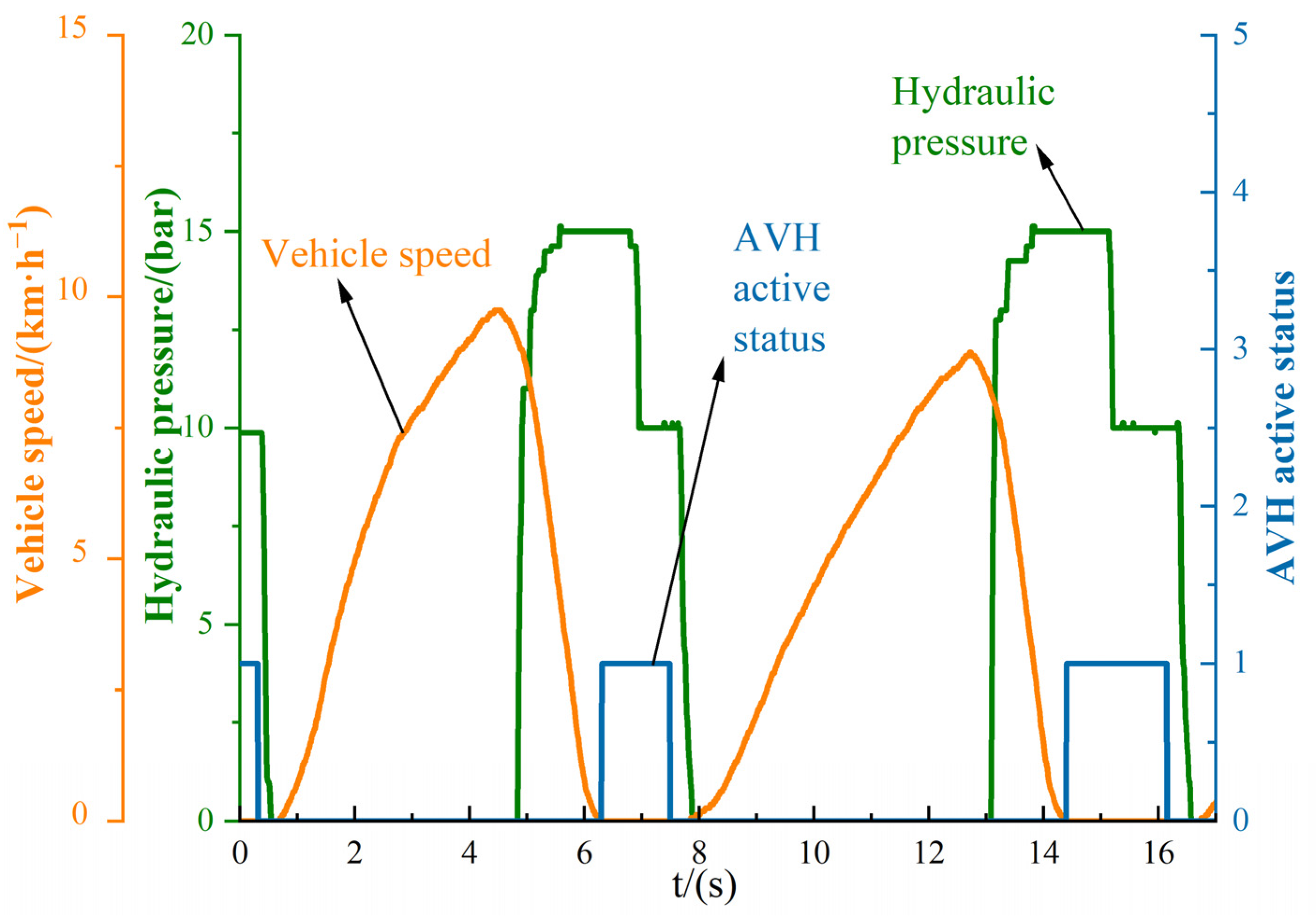
According to Figure 12 and Figure 13, which show Acc-pedal opening, Brake pedal status, and Slope angle, and Vehicle speed, AVH active status, and Hydraulic pressure, respectively, when the vehicle is travelling on a 7% slope, in the period of 0–4 s, as the driver depresses the accelerator pedal the vehicle speed rises at a constant rate, the brake fluid pressure is kept at 0, and the gradient where the vehicle is located varies according to the actual gradient conditions. At 4–7 s, the brake pedal status signal changes from 0 to 1, showing that the driver steps on the brake pedal. At this time, hydraulic pressure rises, and the vehicle speed is about to fall to zero. The AVH active status signal changes from 0 to 1, indicating that the AVH function is in a state of pressure preservation. When the driver releases the brake pedal, at this time, the vehicle still meets the hydraulic pressure. When the driver releases the brake pedal, the vehicle still meets the hydraulic pressure state. The vehicle speed does not change until the driver steps on the accelerator pedal. Hydraulic pressure gradually fades, the AVH active status signal changes from 1 to 0, the vehicle speed rises, and the vehicle completes the starting action.
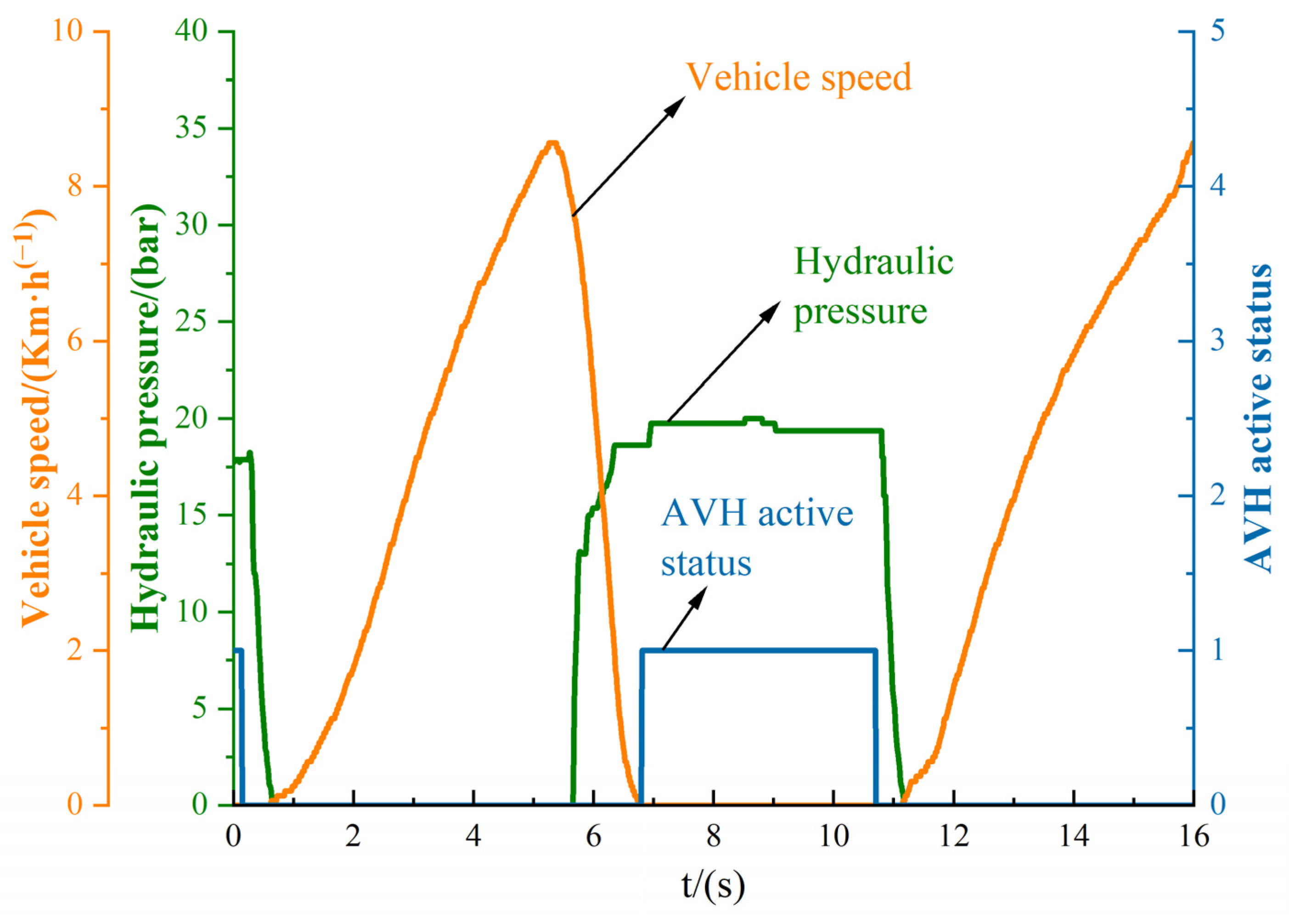
Figure 13 and Figure 14 show, respectively, The acc-pedal opening, Brake pedal status, and Slope angle, and Vehicle speed, AVH active status, and Hydraulic pressure. When the vehicle is travelling on a 15% ramp, the driver depresses the accelerator pedal. During 0–5 s, the vehicle speed rises at a constant rate, the hydraulic pressure remains at 0, and the ramp angle changes according to the actual ramp conditions.
At 5–9 s, the driver steps on the brake pedal, and the brake pedal status signal changes from 0 to 1. The brake fluid pressure rises and the vehicle speed is about zero. For the sensor, when the vehicle rises at a constant speed on the ramp, the angle value of the ramp sensor remains unchanged. In contrast, when the vehicle is under braking conditions, the value of the slope sensor will change according to the actual situation due to the sudden change in the acceleration of the vehicle. When the vehicle is stable, the sampling value of the sensor will regress to the actual slope angle, which is in line with the actual situation.
In the 7–11 s period, the AVH active status signal changes from 0 to 1, indicating that the AVH function at 9–11 s is pressure preservation when the driver releases the brake pedal. The vehicle still meets the hydraulic pressure required to maintain the vehicle parking status. The vehicle speed does not change until 11 s, after the driver steps on the accelerator pedal to end the parking status. The AVH active status signal changes from 1 to 0. At this time, the hydraulic pressure gradually fades away, the vehicle speed rises, and the vehicle completes the start-up action.

5. Conclusions

The innovations and main points of this article include the following five main points:
(1)
Based on the platform of the electro-hydraulic braking system, the automatic vehicle hold function software is designed to improve the driver’s leg convenience and reduce the risk of skidding on ramps when the vehicle is parked and started. In this paper, a complete automatic vehicle hold system is designed by building a Simulink/Matlab model to ensure the vehicle is stably parked and started on flat ground and ramps.
(2)
The software function designed in this paper can preset the target hydraulic pressure directly through calibration. At the same time, multi-level ramp angle switching to different target hydraulic pressure module designs meets the needs of the vehicle parked at different ramp angles, increasing the adaptability of the software to facilitate the vehicle test and the optimisation of hydraulic parking control for the electro-hydraulic braking system.
(3)
Based on the functional software designed in this paper, the systen can compare the automatic start of the car without the software by using the functional software. After using the functional software, the vehicle holds and starts entirely according to the driver’s driving intention. According to the experiment, there is no slope slip. At the same time, unlike the slope start assistance function, the traditional function can only provide 2–3 s of brake fluid pressure, while this function can make the vehicle move when the driver intends to start.
(4)
Different from other research on automatic vehicle hold functions, this paper does not involve the design of auto parts in this research. The research focus of this paper is the feasibility of starting and parking based on the logic strategy of the software, and participates in the research of the software by analysing the parking logic, and finally confirms the automatic vehicle hold function’s reliability through the experimental results of different levels of ramps.
(5)
Because this paper is only based on the Matlab/Simulink logic framework designed to verify the function of an automatic vehicle hold, it needs to show a complete hydraulic pressure control model. However, because the Matlab/Simulink module for hydraulic pressure control is too large and complex, this paper will not introduce it.

Author Contributions

Conceptualization, Y.Z. and T.Z.; methodology, Y.Z.; software, B.H.; validation, B.H.; formal analysis, J.L.; investigation, Y.Z.; resources, B.H.; writing—original draft preparation, Y.Z.; writing—review and editing, J.L.; visualization, B.H.; supervision, T.Z. All authors have read and agreed to the published version of the manuscript.

Funding

This research was funded by the National Key R&D Program of China, grant number “2021YFA1500900”.

Data Availability Statement

No applicable.

Conflicts of Interest

The authors declare no conflict of interest.

Abbreviation

AbbreviationFull Title
AVHAutomatic Vehicle Hold
EHBElectro Hydraulic Brake System
ThdThreshold Value
GrdGradient
LvLevel
PTarTarget Pressure
VehVehicle

References

  1. Hu, C.; Pan, G.; Kong, L.; Yu, J. Research of Brake by Wire System. J. Phys. Conf. Ser. 2023, 2479, 012051. [Google Scholar] [CrossRef]
  2. Hua, X.; Zeng, J.; Li, H.; Huang, J.; Luo, M.; Feng, X.; Xiong, H.; Wu, W. A Review of Automobile Brake-by-Wire Control Technology. Processes 2023, 11, 994. [Google Scholar]
  3. Pugi, L.; Alfatti, F.; Berzi, L.; Favilli, T.; Pierini, M.; Forrier, B.; D’hondt, T.; Sarrazin, M. Fast Modelling and Identification of Hydraulic Brake Plants for Automotive Applications. Int. J. Fluid Power 2020, 21, 169–210. [Google Scholar] [CrossRef]
  4. Pulcinelli, A.; Pugi, L.; Vinattieri, F.; Capitani, R.; Annicchiarico, C. Design and testing of an innovative electro-hydraulic actuator for a semi-active differential. Proc. Inst. Mech. Eng. Part D J. Automob. Eng. 2018, 232, 1438–1453. [Google Scholar] [CrossRef]
  5. Zhao, J.; Chen, Z.; Zhu, B.; Wu, J. Precise Active Brake-Pressure Control for a Novel Electro-Booster Brake System. IEEE Trans. Ind. Electron. 2020, 67, 4774–4784. [Google Scholar] [CrossRef]
  6. Yalun, L.; Bo, H.; Wei, W.; Jun, H.; Qiang, S. EHB system application software design based on model development. J. Mod. Electron. Technol. 2023, 46, 119–124. [Google Scholar]
  7. Wang, J.; Sun, N.; Yan, J.; Song, D.; Wang, Q. Development and experimental validation of an automatic parking brake system with less driveline sensor. Sci. China Technol. Sci. 2018, 61, 1628–1641. [Google Scholar] [CrossRef]
  8. Vaibhav, R.; Prabha, N.A.; Indragandhi, V.; Bharathidasan, M.; Vasantharaj, S.; Alaric, J.S. Autonomous Braking System Using Linear Actuator. J. Sens. 2022, 2022, 7707600. [Google Scholar] [CrossRef]
  9. Chang, L.; Dai, J.; Liu, S. Design and feasibility analysis of a novel auto hold system in hydrostatic transmission wheeled vehicle. Automatika 2020, 61, 35–45. [Google Scholar] [CrossRef]
  10. Ma, C.; Wang, X.; Xu, T.; Wang, J.; Feng, P. Research on a novel electro-hydraulic brake system and pedal feel control strategy. Proc. Inst. Mech. Eng. 2023, 237, 1681–1694. [Google Scholar] [CrossRef]
  11. Meng, D.; Zhang, L.; Yu, Z. A dynamic model for brake pedal feel analysis in passenger cars. Proc. Inst. Mech. Eng. Part D J. Automob. Eng. 2016, 230, 955–968. [Google Scholar] [CrossRef]
  12. Kim, Y.; Choi, Y.; Lee, J.; Noh, J.; Bien, F. Displacement sensor circuit using eddy current for automobile brake. Electron. Lett. 2010, 46, 1504–1505. [Google Scholar] [CrossRef]
  13. Jian, Z.; Jin, Z.; Bing, Z. Development and Verification of the Tire/Road Friction Estimation Algorithm for Antilock Braking System. Math. Probl. Eng. 2014, 2014, 786492. [Google Scholar]
  14. Yong, J.-W.; Gao, F.; Ding, N.-G.; He, Y.-P. Pressure-tracking control of a novel electro-hydraulic braking system considering friction compensation. J. Cent. S. Univ. 2017, 24, 1909–1921. [Google Scholar] [CrossRef]
  15. Kubiš, M.; Beňo, P. Realization of communication via the CAN bus. Transp. Res. Procedia 2019, 40, 332–337. [Google Scholar] [CrossRef]
  16. Lingman, P.; Schmidtbauer, B. Road Slope and Vehicle Mass Estimation Using Kalman Filtering. Veh. Syst. Dyn. 2002, 37, 12–23. [Google Scholar] [CrossRef]
  17. Han, W.; Xiong, L.; Yu, Z. Braking pressure control in electro-hydraulic brake system based on pressure estimation with nonlinearities and uncertainties. Mech. Syst. Signal Process. 2019, 131, 703–727. [Google Scholar] [CrossRef]
  18. Liu, H.; Wei, L.; Liu, H.; Wu, J.; Li, L. Brake Pressure Estimation of the Integrated Braking System Considering Vehicle Dynamics. Actuators 2022, 11, 329. [Google Scholar] [CrossRef]
  19. Muro, T.; Shigematsu, T. Automatic control system of a rear-wheel drive vehicle moving on a sloped weak sandy terrain. J. Terramech. 1998, 35, 239–263. [Google Scholar] [CrossRef]
  20. Wu, L.; Wang, H.; Pi, D.; Wang, E.; Wang, X. Hill-Start of Distributed Drive Electric Vehicle Based on Pneumatic Electronic Parking Brake System. IEEE Access 2020, 8, 64382–64398. [Google Scholar] [CrossRef]
  21. Manuel, C.J.; Santos, M.M.; Tusset, A.M. Mathematical modeling attributed to kinematics and dynamics of a vehicle with 4-wheels. Eur. Phys. J. Spec. Top. 2021, 230, 3663–3672. [Google Scholar] [CrossRef]
  22. Xiong, L.; Xia, X.; Lu, Y.; Liu, W.; Gao, L.; Song, S.; Han, Y.; Yu, Z. IMU-Based Automated Vehicle Slip Angle and Attitude Estimation Aided by Vehicle Dynamics. Sensors 2019, 19, 1930. [Google Scholar] [CrossRef]
  23. Cerezo, V.; Conche, F. Risk assessment in ramps for heavy vehicles—A French study. Accid. Anal. Prev. 2016, 91, 183–189. [Google Scholar] [CrossRef]
  24. Wu, Y.; Xu, Y.; Zhou, J.; Wang, Z.; Wang, H. Research on Starting Control Method of New-Energy Vehicle Based on State Machine. Energies 2020, 13, 6249. [Google Scholar] [CrossRef]
  25. Rupam, B.; Sanjay, M.; Chaman, V. Cogging Torque Minimization of PMBLDC Motor for Application in Battery Electric Vehicle. J. Electr. Eng. Technol. 2022, 18, 1733–1743. [Google Scholar]
  26. Ihor, S.; Daniel, J. Electromagnetic Torque Ripple in Multiple Three-Phase Brushless DC Motors for Electric Vehicles. Electronics 2021, 10, 3097. [Google Scholar]
  27. McCall, C.J.; Trivedi, M.M. Driver Behavior and Situation Aware Brake Assistance for Intelligent Vehicles. Proc. IEEE 2007, 95, 374–387. [Google Scholar] [CrossRef]
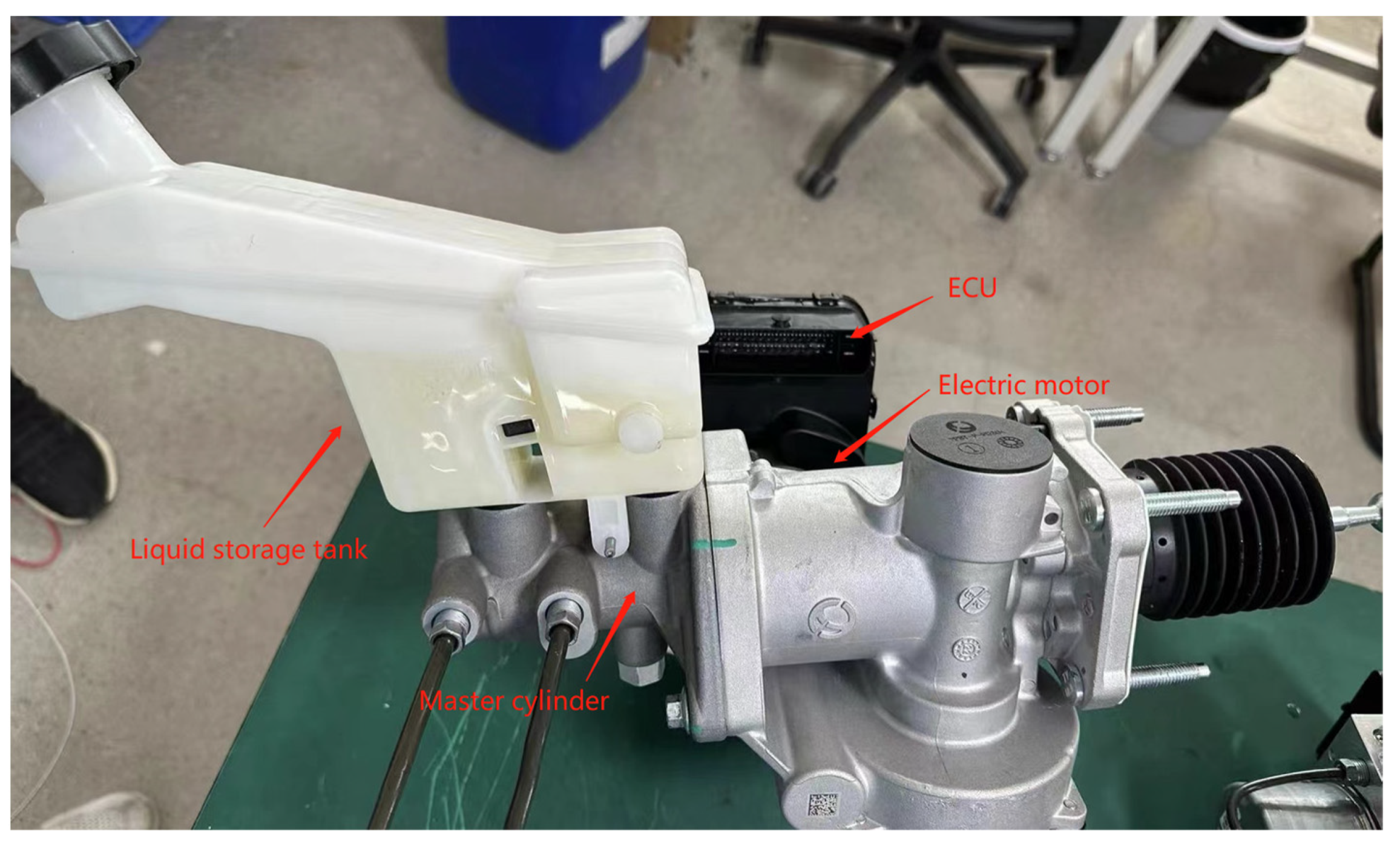
Figure 1. Physical diagram of the electro-hydraulic braking system.
Wevj 14 00277 g001
Figure 2. External diagram of the calculation module.
Wevj 14 00277 g002
Figure 3. Internal diagram of the calculation module.
Wevj 14 00277 g003
Figure 4. Block diagram of park function module.
Wevj 14 00277 g004
Figure 5. Vehicle automatic parking force diagram.
Wevj 14 00277 g005
Figure 6. Variation of force at each stage of automatic vehicle hold.
Wevj 14 00277 g006
Figure 7. Flowchart of automatic vehicle hold strategy.
Wevj 14 00277 g007
Figure 8. Parking diagram when AVH is not enabled under no-slope condition.
Wevj 14 00277 g008
Figure 9. Relationship between accelerator pedal and torque output.
Wevj 14 00277 g009
Figure 10. Parking diagram with AVH on under no-slope conditions.
Wevj 14 00277 g010
Figure 11. Parking diagram at 7 percent gradient (a).
Wevj 14 00277 g011
Figure 12. Parking diagram at 7 percent gradient (b).
Wevj 14 00277 g012
Figure 13. Parking diagram at 15 percent gradient (a).
Wevj 14 00277 g013
Figure 14. Parking diagram at 15 percent gradient (b).
Wevj 14 00277 g014
Table 1. Table of test vehicle parameters.
Parameter NameNumerical ValueParameter NameNumerical Value
Mass of vehicle1220 kgTotal motor torque120 Nm
wheelbase2260 mmTyre radius0.285 m
Front track width1470 mmHeight of centre of mass0.48 m
Rear track width1460 mmMoment of inertia1490 kg·m2
coefficient of drag0.35Front area2.2
Correction coefficient of rotating mass1.3Main Reducer Ratio7.6
Rolling resistance coefficient0.011Mechanical efficiency of the transmission system0.91
Disclaimer/Publisher’s Note: The statements, opinions and data contained in all publications are solely those of the individual author(s) and contributor(s) and not of MDPI and/or the editor(s). MDPI and/or the editor(s) disclaim responsibility for any injury to people or property resulting from any ideas, methods, instructions or products referred to in the content.