Article

Experimental Study on Effects of Triggering Modes on Thermal Runaway Characteristics of Lithium-Ion Battery

College of Transportation and Vehicle Engineering, Shandong University of Technology, Zibo 255049, China
*
Author to whom correspondence should be addressed.
World Electr. Veh. J. 2023, 14(10), 270; https://doi.org/10.3390/wevj14100270
Submission received: 28 August 2023 / Revised: 17 September 2023 / Accepted: 25 September 2023 / Published: 27 September 2023

Abstract

:
As an important component of new energy vehicles, the safety of lithium-ion batteries has attracted extensive attention. To reveal the mechanism and characteristics of ternary lithium-ion batteries under different trigger modes, an experimental system was established. The effects of different trigger modes on battery surface temperature, battery internal temperature, injection time, and battery voltage were analyzed. Among them, acupuncture, overheating, and overcharging are used as trigger conditions for mechanical, thermal, and electrical abuse. The results show that the injection time and surface peak temperature are positively correlated with the energy input before thermal runaway. Before the cell triggers abuse, the more input energy, the higher the cell surface temperature, the more serious the thermal runaway, and the higher the damage to the surrounding battery system. Under the same conditions, the intensity and damage degree of overcharge thermal runaway are greater than those of internal short circuit and overtemperature. The abnormal change of voltage suddenly rising and rapidly falling can be used as a condition to judge whether overcharge thermal runaway occurs. Finally, according to the temperature curves at different positions, the thermal diffusion law under different abuse conditions is summarized, which provides a basis for the safety design of the battery module.

1. Introduction

With the changes in global industrialization and escalating energy consumption, the automotive industry is moving towards electrochemical energy storage systems [1,2]. Lithium-ion batteries have the advantages of high energy density, wide use conditions, and long cycle life. Lithium-ion batteries have become the mainstream choice for energy storage systems such as electric vehicle power systems and energy storage power stations [3,4,5]. However, in order to improve the driving range of electric vehicles, the energy density of lithium-ion batteries is increasing, and as the thermal safety of batteries is becoming more and more serious, the intrinsic safety of lithium batteries is still not fundamentally guaranteed [6,7,8]. When thermal runaway occurs in the local area of the battery, it will cause explosion of the single battery and even the system, causing serious safety hazards [9,10,11]. Therefore, in the development and application of lithium-ion power batteries, it is indispensable to consider the degree of hazard under different triggering modes.
Mechanical abuse, electrical abuse, and heat abuse are the main causes of thermal runaway of the battery [12]. A thermal runaway experiment is an intuitive manifestation of battery thermal runaway behavior. It is an important means to understand the mechanism and behavior characteristics of thermal runaway. It is suitable for studying various extreme and abused safety problems of batteries. Therefore, it is mostly used for research thermal safety issues of LiFeO4, LiCOO2, and LiMnO4 batteries in order to reveal the mechanism of abuse [13], characteristic changes [14,15], affecting factors [16,17], and the corresponding blocking protection mechanism [18,19], as well as to verify the thermal abuse model, etc. [20].
Lai et al. [21] comparatively researched the characteristics of thermal extension of the cathode active material (Liy(NiCoMn)1/3O2 (NCM)-LiyMn2O4 (LMO)) composite cathode, with the anode being graphite battery, under different triggering methods. It was found that the triggering method has a differentiated effect on the abuse of the first cell in terms of time and temperature, and the nail-triggered thermal runaway has a short time but the heating trigger has a good overall performance. Feng et al. [22] conducted a heating-triggered thermal runaway study on a large-size prismatic battery. It was found that there is a 15–40 s interval between the sharp dip in voltage and the sharp rise in temperature, which can provide passengers and drivers with escape time. Wang et al. [23] used a combination of experiment and simulation to simulate the thermal behavior of lithium batteries during charging and discharging, and they predicted thermal runaway and obtained better results. Huang et al. [24] conducted experimental research on the combustion characteristics of cells. It was found that as the State of Charge (SOC) increases, the time required for the battery to reach the thermal runaway condition decreases. In addition, in view of the thermal safety of lithium battery packs, Ashok et al. [25] conducted a comprehensive review of the battery management system control strategy, providing a basis and direction for the safety design of safer and smarter automotive power batteries.
In summary, experts have focused on the mechanism of different thermal runaway triggering methods, without considering that the contact surface temperature and heat spread trend are crucial to the thermal safety of the battery module during the battery grouping process. In this paper, a soft-packed ternary lithium battery was used as the experimental object. A contrast test of thermal runaway triggered by lateral acupuncture lateral heating and overcharging was carried out. The thermal runaway temperature and voltage characteristics under three abuse conditions were compared and the degree of harm under three abuse conditions was compared based on monitoring data. Considering that the surface temperature of the battery is in direct contact with the adjacent battery during the battery grouping process, when any position on the surface of the adjacent battery reaches the thermal trigger temperature, it will cause thermal runaway spread. According to the temperature curves at different positions on the surface, the thermal diffusion rules under different abuse conditions are summarized. According to the temperature distribution of the cell, it provides a basis for improving the safety of ternary lithium batteries for vehicles.

2. Thermal Abuse Experiments under Different Triggering Methods

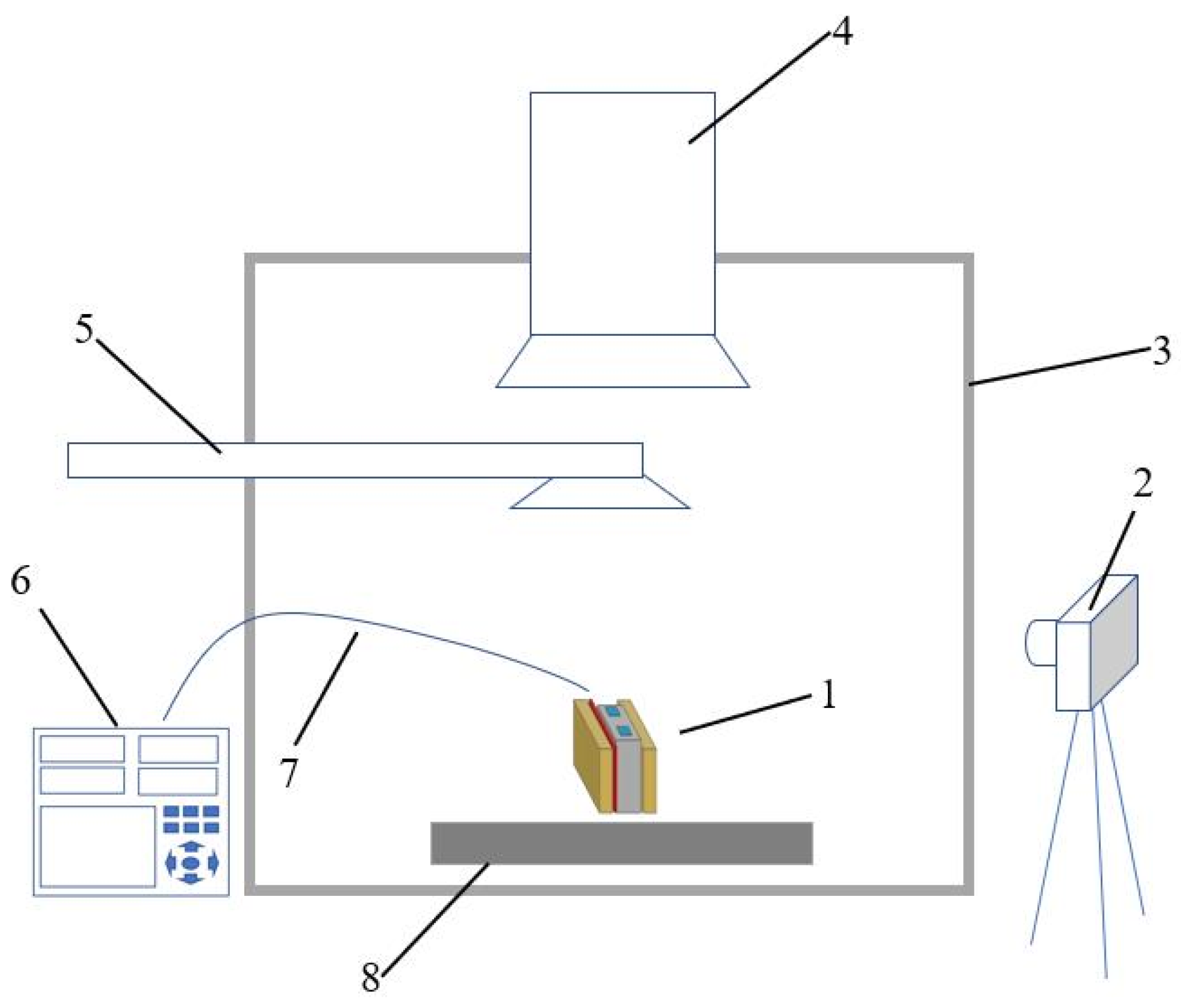
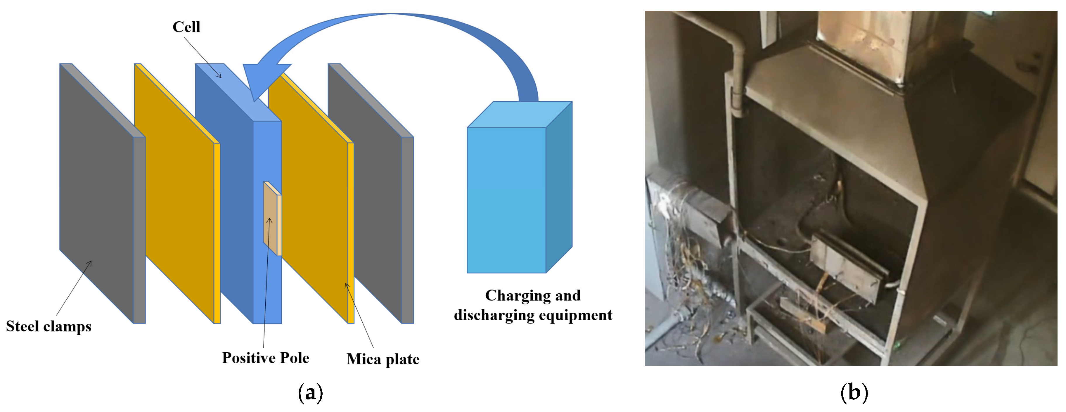
2.1. Experimental Systems

The 53 Ah battery used in this paper has Li(Ni0.7Co0.2Mn0.1)O2 (NCM 721)/graphite as its electrodes. The battery size is 268 mm × 102 mm × 11.5 mm and the cutoff voltage is 4.2 V and 2.8 V for charging and discharging. When thermal runaway occurs, there is a large temperature difference between the center and the surface of the battery. Therefore, a K-type thermocouple (Omega TMM China, Nanjing, China, GG-K-30) was selected. The selected thermocouple has a fine diameter (diameter 0.9 mm), and the measurement error is ±0.5 °C, which is suitable for measuring the internal temperature of the battery in the soft package battery. In addition, there is a layer of glass fiber wrapped on the surface of the thermocouple sensing line, which can work at 500 °C for a long time, and can work at 800 °C in a short time (less than 5 min). When the battery is out of control, it will reach 800 °C in a very short time, and the duration is short. Therefore, it can meet the measurement data in high-temperature environment.
The steps of thermocouple implantation are shown in Figure 1b–d. First, the cell is discharged to a 0% state of charge (SOC) to ensure safety. The first step of implanting the thermocouple is to use the blade to cut the middle position of the battery side, and the incision is about 0.5–0.8 cm. it should be noted that the blade used needs to be an insulating ceramic blade to avoid electric shock and short circuit. In the second step, the thermocouple is inserted from the notch to the battery pole piece using the prepared guide rod. When the thermocouple’s temperature-sensing probe reaches a predetermined position, the nylon guide rod tail is rotated and removed from the inside of the cell. At this time, the temperature-sensitive probe of the thermocouple is wrapped by polyimide tape and is inside the battery, which can be used to test the middle temperature of the cell. Finally, the incision of the aluminum plastic film is sealed with sealant. So far, the thermocouple implantation operation of the soft packet battery is completed. The battery voltage is checked after standing for a period of time to ensure that the battery is not affected during the built-in thermocouple. The whole operation process needs to be carried out in a drying chamber with a temperature of 25 °C. During the experiment, a pre-tightening force of 1 N/m was provided, and a polyimide tape was used to tightly wrap the thermocouple and the battery surface to ensure the accuracy of the collected data. In addition, Xu [26] carried out charge–discharge experiments on batteries implanted with thermocouples. The influence of the built-in thermocouple on its capacity was explored. The results show that the influence of the thermocouple implanted inside the battery on the capacity of the soft pack battery can be ignored.
The battery thermal runaway experimental system used in this experiment is shown in Figure 2. It consists of experimental devices with different trigger modes, video recorders, explosion-proof boxes, exhaust devices, spray devices, data acquisition devices, thermal insulation devices, sensors, etc. At the beginning of the experiment, different trigger methods (acupuncture, lateral heating, overcharge) were used to trigger the thermal runaway of the battery cell in the experimental system.

2.2. Experiment Content

Mechanical, heat, and electric heat abuse are the main causes of battery thermal runaway. Thermal runaway of mechanical abuse is usually caused by collision, extrusion, and other forms. In the experiment, the separator is often pierced by acupuncture experiment, causing the internal short circuit to trigger thermal runaway. Thermal inducement usually causes local overheating of the battery due to virtual welding or aging of the battery, which in turn causes thermal runaway of the battery. In the experiment, the overheating condition is simulated by lateral heating. When the battery temperature reaches the melting temperature of the separator, the internal short circuit is caused, the heat release is huge, and the battery thermal runaway is caused. Electrically induced thermal runaway is usually caused by excessive battery charging strategy, battery management system (BMS) failure. In the experiment, thermal runaway is generally triggered by overcharging. During the overcharging process, lithium dendrites pierce the separator, which in turn triggers thermal runaway.

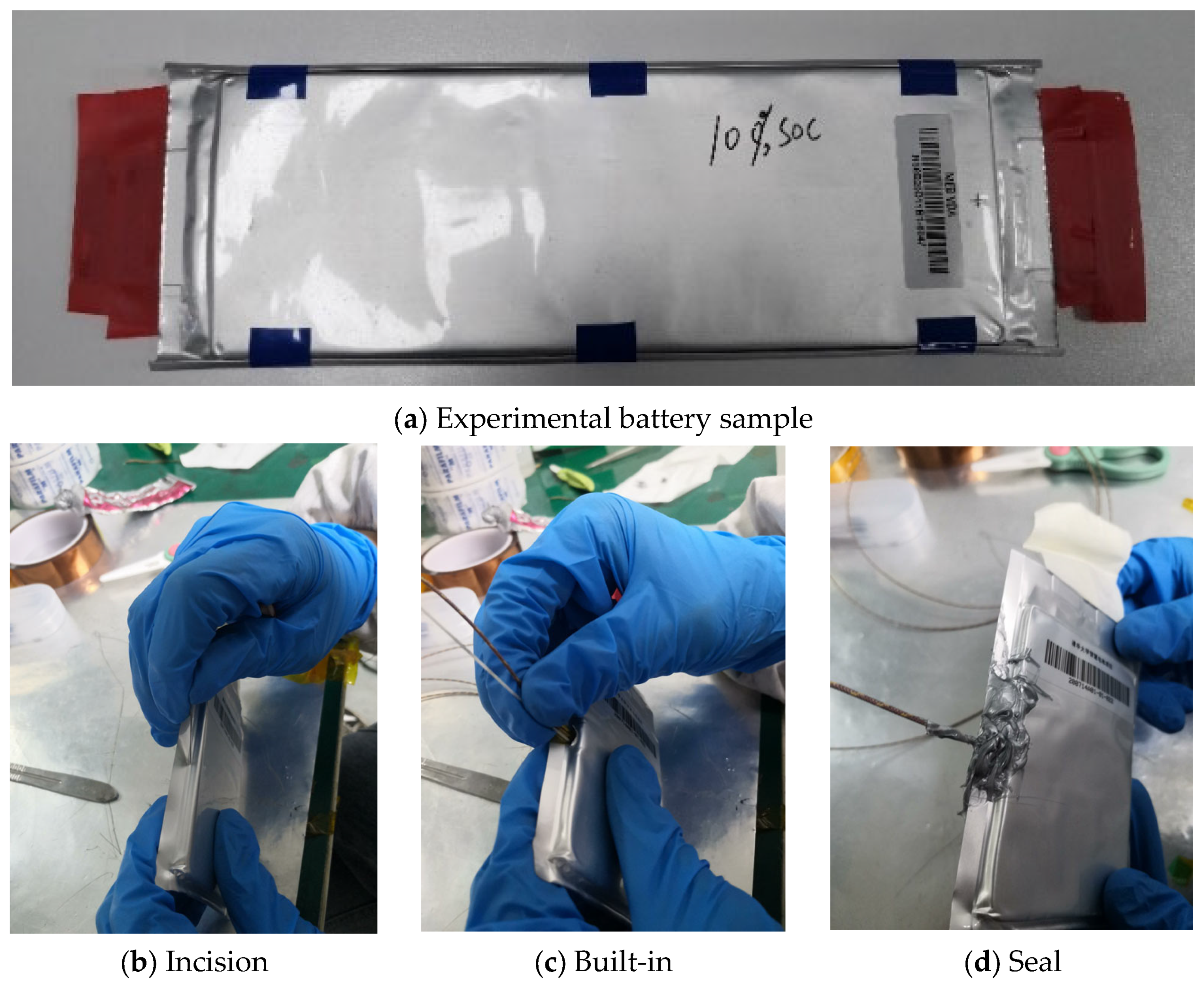
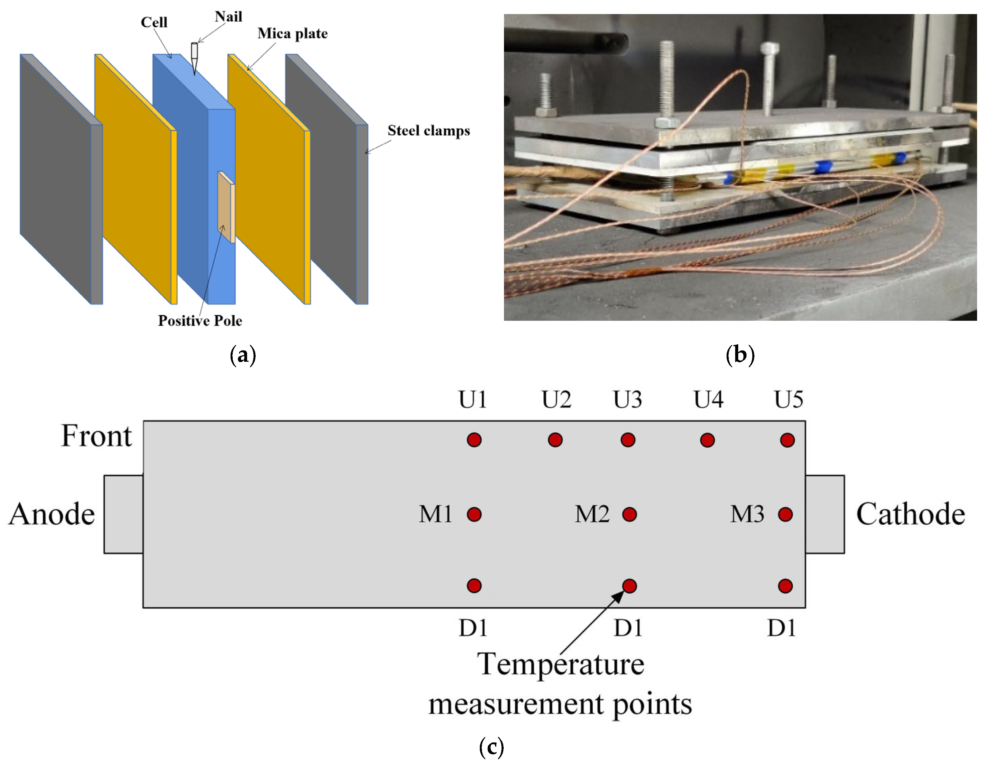
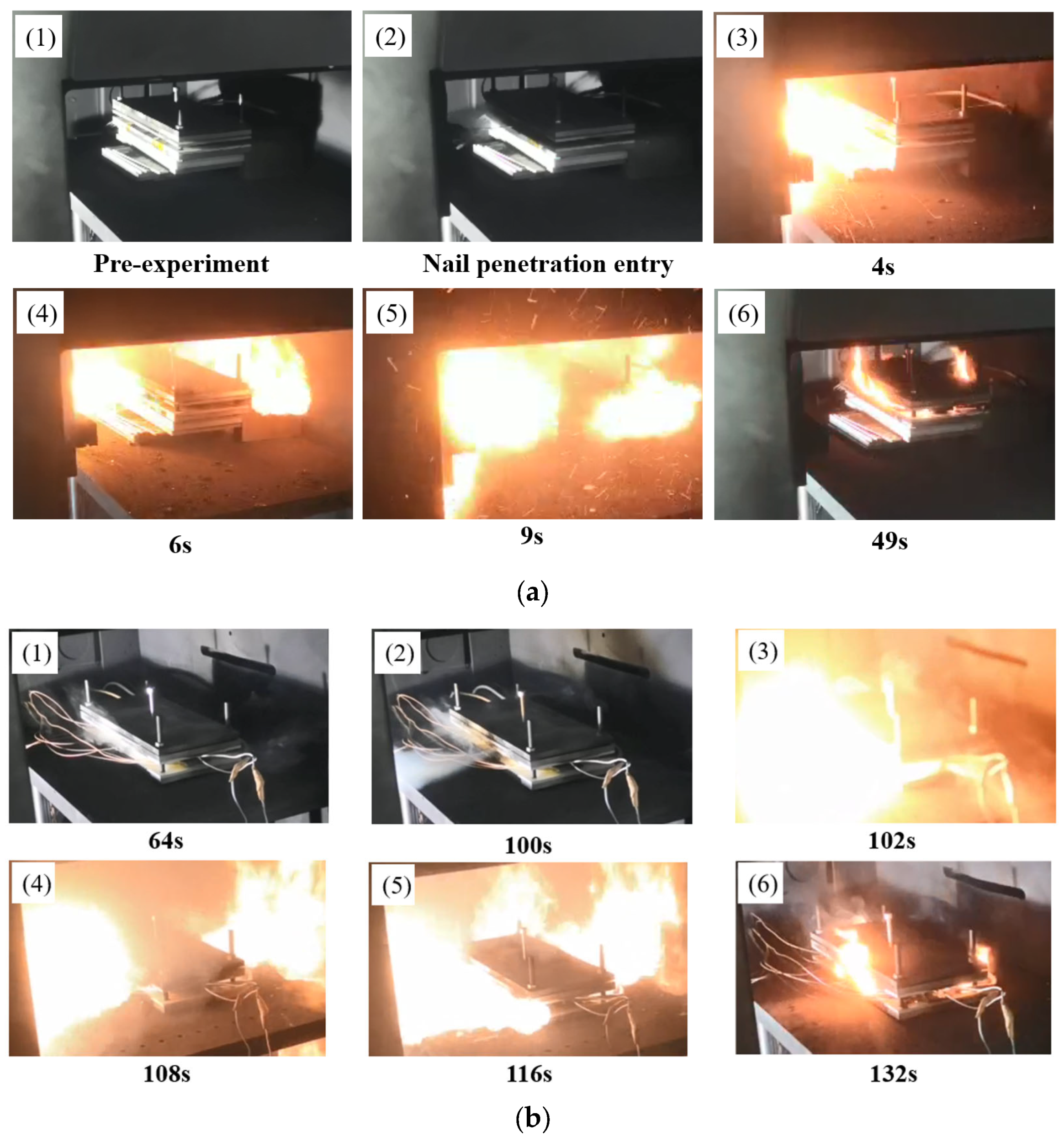
2.2.1. Lateral Nail Penetration Experiment

Battery tests with nail penetration are considered the most severe battery thermal safety tests. Different penetration positions cause different types of battery damage, and the nail position is often in the center of the cell. In this text, we conducted a thermal runaway experiment with a nail at the center of the side of the cell.
Figure 3a,b are the diagrammatic drawing and physical image of the battery side center nail experimental device. First, the battery is charged to 100% SOC. To ensure the stability and a certain preload of the battery during the acupuncture test, a stainless-steel bracket with a thickness of 9 mm was used to fix the battery. Considering the good thermal conductivity of iron, in order to prevent excessive heat transfer, the measured surface temperature is affected. A 10 mm thick piece of mica was placed between the battery and the bracket. Secondly, a nail with a diameter of 3 mm was selected to pierce the battery from the side center at a speed of 80 mm/s, causing the battery thermal runaway. Figure 3c is the thermocouple layout scheme of the nail penetration experimental battery, which monitors and records the changes of voltage and temperature under nail penetration.

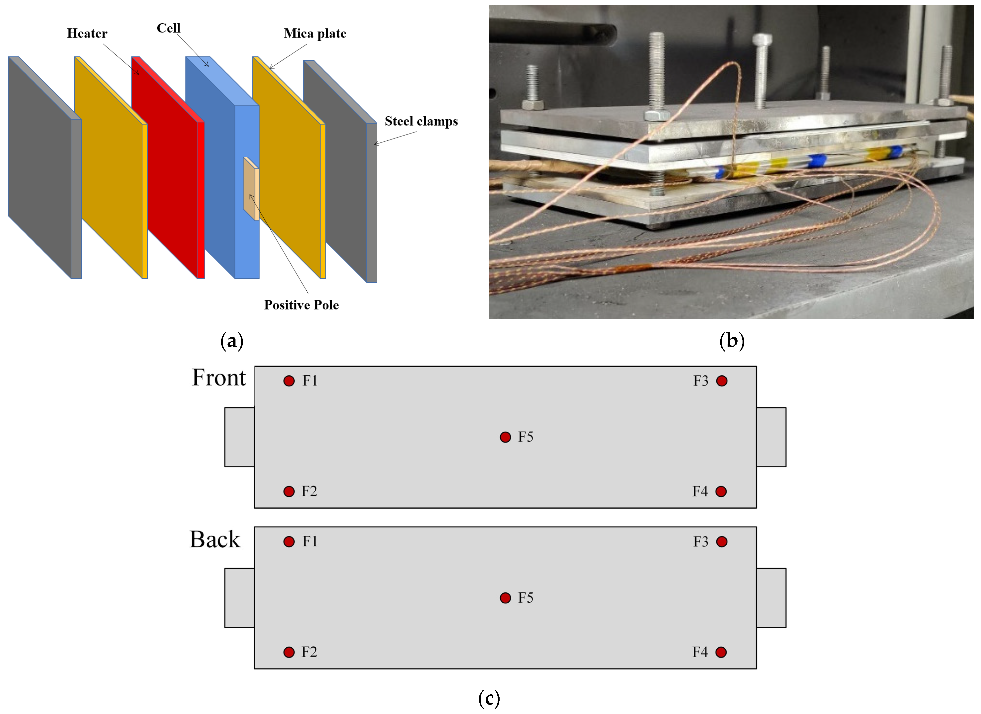
2.2.2. Lateral Heating Experiment

The lateral heating experiment used a steel heating plate with the same size as the front of the battery. The heater with a thickness of 3 mm and a power of 750 W heats the 100% SOC battery until it triggers the thermal runaway. The heating plate is placed between the mica plate and the battery. The diagrammatic drawing of the experimental device is shown in Figure 4a, and the experimental physical diagram is shown in Figure 4b. The lateral heating thermal runaway experimental device is composed of an experimental battery, mica plate, steel fixture, and heater. The function of steel fixture is to clamp mica plate and battery in the middle and provide certain preload. In the lateral heating experiment, a 220 V regulated power supply is needed to connect the heater.
The temperature measurement point arrangement scheme of the battery surface in the lateral heating test is shown in Figure 4c, which is used to monitor the temperature changes of the cell during the heating process until it is out of control.

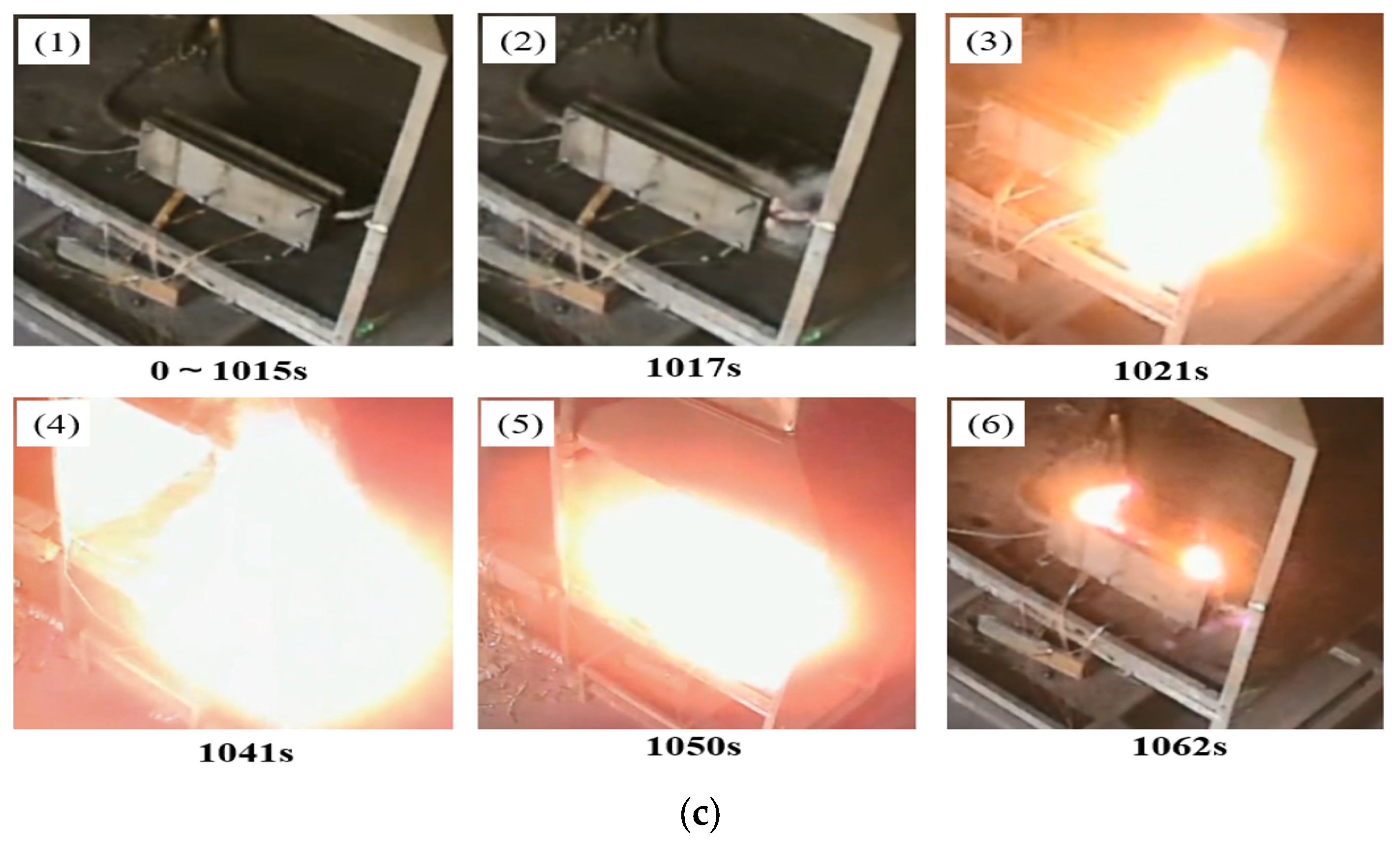
2.2.3. Overcharge Experiment

The 100% SOC battery is charged by a charging and discharging device at a current of 1 C until the battery is thermally runaway. The diagrammatic drawing of the overcharge experimental device is shown in Figure 5a, and the physical diagram is shown in Figure 5b. The overcharge triggering thermal runaway experimental device is composed of experimental batteries, mica plates, steel fixtures and charge–discharge machines. In the overcharge experiment, the arrangement of the battery temperature measurement points is consistent with the lateral heating arrangement.

2.3. Experimental Evaluation Index

In the abuse trigger experiments of lateral puncture, overheating, and overcharge, the damage degree of thermal runaway caused by different trigger methods was evaluated by the peak surface temperature, the peak internal temperature, and the jet duration.
The battery surface and internal temperature change were monitored during the abuse process. In terms of the highest surface temperature, the highest temperature of each position on the surface of the cell in the thermal runaway text of different trigger modes was compared, and the highest value was taken.
Injection duration of battery thermal runaway:
D nail = t 1 , nail t 0 , nail
D heat = t 1 , heat t 0 , heat
D charge = t 1 , charge t 0 , charge
where Dnail, Dheat, Dcharge is the injection duration of thermal runaway; t1,nail, t1,heat, t1,charge is the end time of injection; t0,nail, t0,heat, t0,charge is the onset time of injection.

3. Analysis of Experimental Phenomenon and Results

3.1. Phenomena under Different Abuse Methods

As shown in Figure 6a, when the acupuncture experiment began, a little smoke erupted from the acupuncture position. In the next 4 s, the flammable gas ejected from the nail position was ignited. Within 6 s, the battery’s thermal runaway gradually intensified, and flames erupted from both sides of the cell. The battery went completely out of thermal control within 9 s. At this point, a violently burning flame followed for 22 s around the cell, accompanied by high-temperature grain and smoke. Finally, the inside of the battery completely erupted, and there was a little flame around the cell.
Shown in Figure 6b is the battery side-heating experiment process picture. A small amount of white smoke appeared after heating for 64 s. At 100 s, the side of the battery emitted a lot of white smoke, which signals the thermal runaway of the cell. At 102 s the combustible gas was ignited, and the side of the battery changed from white smoke to a violent combustion flame. At 108 s, the thermal runaway of the cell spread to the other side of the cell, resulting in a violent combustion flame on both sides of the battery. At 116 s was the complete thermal runaway of the battery, and there were flames and smoke around the battery and violent burning. At 132 s, the active material inside the cell was exhausted, the flame eruption stopped, and the residual flame on the surface of the battery continued to burn, and then the flame was extinguished.
Figure 6c is the thermal runaway triggered by overcharging. Before the thermal runaway triggered by overcharge is 0~1015 s, the middle position of the fixture can be seen to be bent, indicating that the battery will bulge during overcharge, and the pressure of bulging is so large that the fixture will bend. At the beginning of the thermal runaway at 1017 s, a little amount of combustible flue gas was first ejected from the cathode of the cell. At 1021 s, the combustible flue gas was ignited, and the cathode of the battery changed from the initial smoke to the flame. In 1021~1050 s, explosion and combustion occurred at the cathode of the battery, resulting in a huge flame. The whole cell was thermally out of control, and the whole battery was on fire. Finally, the material inside the battery burned out, and a small amount of flame remained in the contact part between the battery and the air.

3.2. Analysis of Spreading Tendency under Different Abuse Methods

To ensure the accuracy of the experimental data, three repeated tests were carried out. According to the test results, the experimental data of different trigger modes were compared and analyzed after taking the average value. Considering that the moment of short circuit in the cell will cause thermal abuse, and the trigger time is short, the first 100 s of experimental data were analyzed. Shown in Figure 7a is the temperature curve of the undersurface of the cell. The temperature of the battery increases in turn from the nail position to both ends, and the thermal spread takes 4 s. The highest temperature of the nail position reaches 774.6 °C. Figure 7b shows the temperature curve in the middle surface. The temperature of the battery increases in turn from the center to the two ends. The heat propagation time is 4 s, and the maximum temperature at ‘M1’ reaches 736 °C. Shown in Figure 7c is the temperature curve of the upper side of the battery. The thermal expansion sequence of the upside of the cell is different from that of the middle and lower sides from the midst to both sides, which is messy. The highest temperature appears in the ‘upper 4’ position, which is 716 °C. This shows that the thermal runaway first occurs at the acupuncture site, and then the heat diffuses to other areas inside the cell with the acupuncture position as the origin. However, because the material in the cell is not completely uniform, the heat spread trend inside the cell is an irregular semicircle before the battery is completely thermally out of control.
Figure 7d shows the variation curves of battery internal temperature and voltage. When the nail pierces the separator, the battery voltage first fluctuates from 4.2 V to 3.5 V. At this time, there is a local internal short circuit inside the cell, so the cell voltage only decreases slowly, and does not directly reach 0 V, and the temperature rises slowly. As the separator shrinks, the internal short circuit intensifies and the chemical reaction continuously releases heat, triggering thermal runaway, and the temperature continues to rise. When the temperature of the cell rises to about 950 °C, the voltage drops sharply from 3.5 V to 0 V, and the internal temperature of the cell rises to 1005 °C.
As shown in Figure 7e, during the acupuncture process, the maximum temperature on the cell surface is concentrated at 630 °C to 750 °C, and after about 200 s, it cools down to 400 °C to 600 °C. The highest temperatures inside and outside of the cell are 1005 °C and 774 °C, respectively. The internal temperature rise is much earlier than the surface temperature rise, which indicates that the internal heat of the cell is out of control after nail penetration, and then diffuses from the inside to the outside.
Figure 8a is the front surface temperature process of the side-heating battery changing with time. The average temperature of each point on the surface increased from 24 °C to about 220 °C from the beginning of heating to 100 s. When thermal runaway is triggered the peak temperature of the front surface is 835 °C, which appears in the ‘middle’ position. From the order of temperature rise of each point, the temperature of each point on the front surface increases almost at the same time. This indicates that under the action of the lateral heating of the heater, the internal material of the battery near the heater first undergoes thermal runaway. The temperature change on the back of the cell is shown in Figure 8b. The peak temperature during thermal runaway is 801 °C, which appears in the back 4 position. The messy temperature curve on the back of the battery is caused by the excessive temperature shock at the moment of thermal runaway.
Figure 8c is the temperature change curve of the built-in thermocouple. Due to the effect of lateral heating, the temperature of the battery continues to rise. When the internal temperature reaches the separator contraction temperature, the voltage drop trend is smooth, the voltage fluctuation is small, and there is an interval of about 20 s between the sharp rise of temperature, which is similar to the thermal runaway research results of the heating triggered square shell battery carried out by Feng et al. [22]. When the voltage drops to about 3.2 V, the internal temperature reaches the first peak. At this time, the separator collapses, and the voltage jump drops rapidly to 0 V. The internal temperature further increases during the voltage jump, and the temperature reaches about 970 °C.
Figure 8d shows the total thermocouple temperature of the cell side heating. From the diagram, the trigger temperature is 233 °C, and the surface temperature of the cell after thermal runaway is mostly distributed in 750~790 °C. After thermal runaway about 200 s, the temperature drops to 600~700 °C. the highest surface temperature is 835 °C, and the highest internal temperature is 965 °C. It takes about 20 s for thermal runaway to spread to the rear surface of the cell.
It takes 1020 s to charge the battery from 100% SOC to thermal runaway at 1 C current, and the battery power is 128.3% SOC when it is out of control. As shown in Figure 9, during the overcharge experiment, the battery voltage rose slowly at first and then decreased. When the cell underwent thermal runaway, the battery voltage fluctuated violently, and then the voltage dropped to 0 V. After the start of overcharge, the surface temperature rose slowly. When the surface temperature reached 117 °C, the thermal runaway was triggered, and the temperature rose rapidly. The peak surface temperature reached 935 °C. The maximum temperatures of the positive and negative electrodes are 335 °C and 450 °C, respectively, which are significantly lower than the surface temperature. In the overcharge experiment, the thermal runaway first occurred in the negative electrode, and then the thermal runaway spread to the positive electrode inside the battery. The whole process lasted for 10 s.

4. Comparison and Analysis of Battery Abuse with Different Triggering Methods

The text result of battery thermal runaway under three triggering modes of acupuncture, lateral heating, and overcharge were compared and analyzed. From the perspective of the thermal runaway trigger mechanism of the battery, the mechanism of the thermal runaway triggered by the nail is that the nail pierces the separator to cause a local internal short circuit, and due to the collapse of the separator, the local internal short circuit is converted into a large area of internal short circuit, resulting in the overall battery short circuit causing thermal runaway. The acupuncture trigger time is short, and the thermal runaway trigger temperature is only 42 °C. The lateral heating is due to the temperature rise of the material inside the battery caused by heating. When the temperature reaches the separator collapse temperature, a violent chain exothermic reaction occurs, and the voltage drops sharply, resulting in thermal runaway. When the surface temperature reaches 233 °C, the temperature rises sharply. The mechanism of thermal runaway caused by overcharging is that overcharging leads to lithium precipitation and oxygen release, lithium dendrites pierce the separator, voltage drops sharply, and the internal short circuit leads to severe exothermic reaction. It takes the longest time to trigger thermal runaway, and the initial temperature of thermal runaway is 117 °C, as shown in Figure 10b. Under different trigger modes, the thermal runaway time and temperature of the battery have different effects. The thermal runaway time of the nail trigger is shorter, but the comprehensive performance of the heating trigger is good, which is similar to the experimental results carried out by Lai et al. [21].
As shown in Figure 10a, the side needle trigger battery thermal runaway injection duration is 22 s, the lateral plus test injection duration is 24 s, and the overcharge injection time is 29 s. Because the battery injection stage is the most severe stage, the time of the injection process may reflect to some extent the risk. In addition, from the flame shape caused by the three trigger modes, the deflagration caused by acupuncture and heating does not induce deflagration, the thermal runaway caused by overcharge has a deflagration phenomenon, and the flame combustion is more intense. Therefore, overcharge-triggered thermal runaway is the most harmful, while acupuncture- and lateral-heating-triggered thermal runaway are less harmful. The peak surface temperatures caused by acupuncture, side heating, and overcharging are 774 °C, 835 °C, and 935 °C, respectively.
When thermal runaway occurs, the electrical and chemical energy in the cell are converted into thermal energy within a short period of time. The more energy input, the higher the temperature of the battery. The injection time and the maximum surface temperature are proportional to the energy input before thermal runaway. The highest degree of battery thermal runaway is triggered by overcharge, followed by lateral heating, and the lowest degree of damage is by acupuncture.

5. Conclusions

In this paper, the tests of the battery triggered by acupuncture, lateral heating, and overcharge were conducted, and the effects of different trigger methods on power battery thermal runaway were studied.
(1)
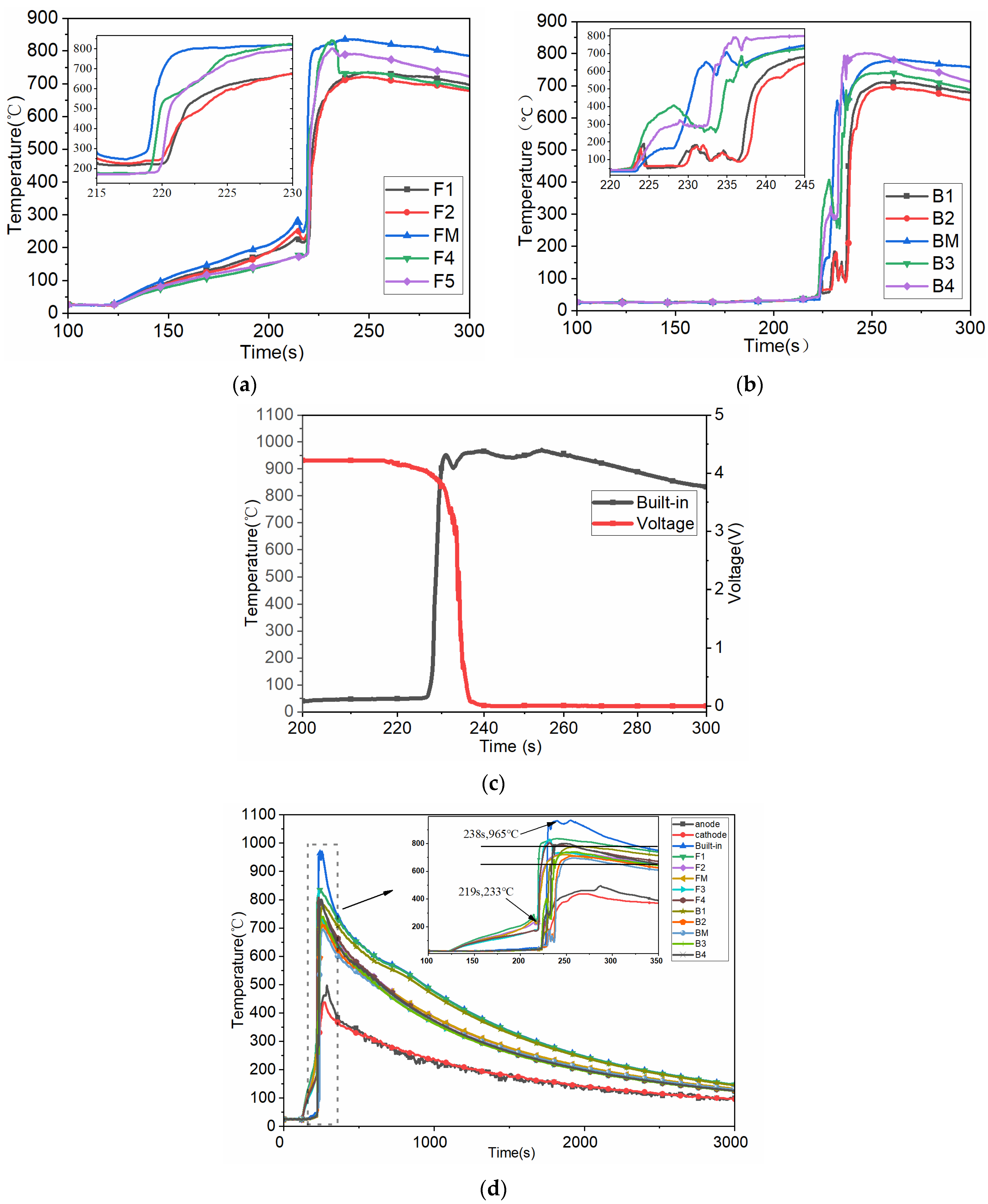
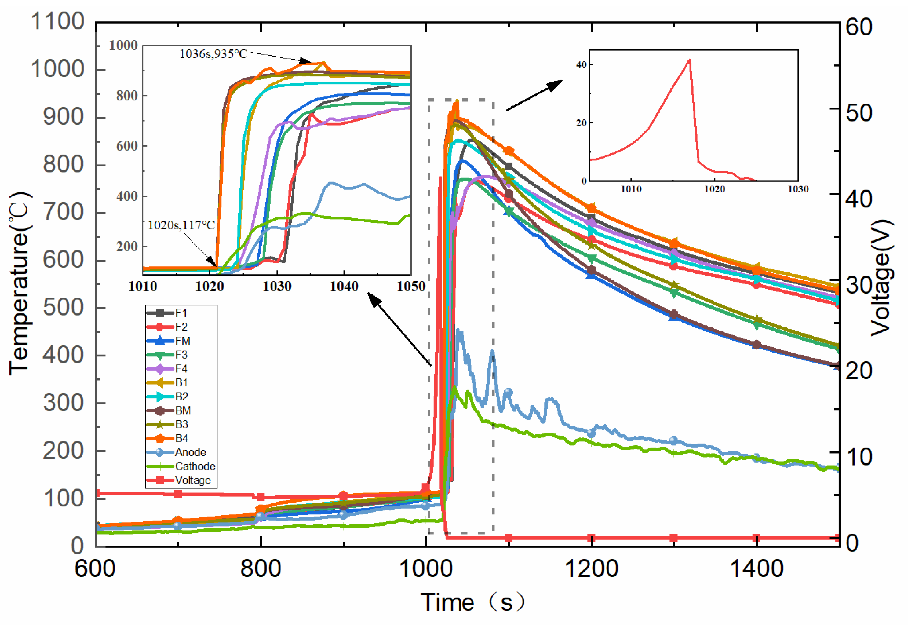
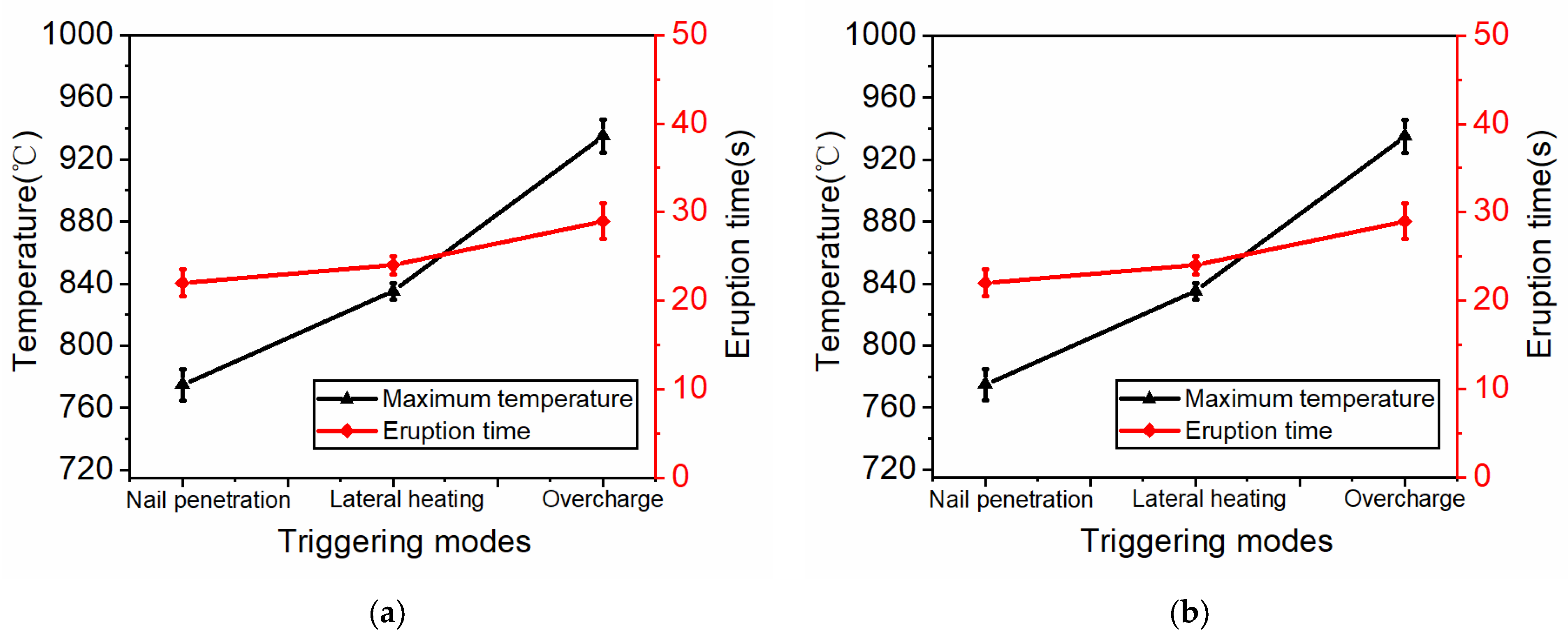
The injection time and the maximum surface temperature are positively correlated with the energy input before thermal runaway. It is found that there is no additional energy input in the needle-triggering method. The peak temperature of the surface in the nail-triggering experiment is 774 °C, and the injection time is shorter when there is thermal runaway. Lateral heating will input energy to the battery in the form of thermal energy. The input energy is related to the heating time, and the maximum temperature of the battery surface reaches 835 °C. The overcharged battery thermal runaway trigger mode inputs energy into the battery in the form of electric energy, and the input energy is the most. Therefore, the eruption time is up to 29 s after thermal runaway, and the maximum temperature of the surface reaches 935 °C. Considering that the surface temperature of the battery is in direct contact with the adjacent battery during the battery-grouping process, when any position on the surface of the adjacent battery reaches the thermal runaway trigger temperature, it will cause thermal runaway spread. The maximum surface temperature of the battery in the most extreme cases should be considered, and corresponding thermal spread suppression measures should be taken. Under the same conditions, the intensity and destructiveness of the battery overcharge thermal runaway behavior are greater than the internal short-circuit thermal runaway caused by acupuncture and the overtemperature thermal runaway caused by thermal abuse. It shows that before the battery triggers thermal runaway, the more total energy stored inside the battery, the higher the degree of damage to the surrounding battery system.
(2)
The time of thermal runaway triggered by acupuncture is the shortest, the triggering temperature of thermal runaway is 42 °C, the thermal runaway triggered by overcharge needs 1020 s, the triggering temperature is 117 °C, and the triggering temperature of lateral heating thermal runaway is 233 °C. In the process of using a power battery, it is necessary to pay attention to the harm of battery thermal runaway caused by collision and extrusion in a short time.
(3)
According to the temperature curve, in the acupuncture experiment, the thermal diffuses from the nail position to other places. The trend of thermal runaway spread is an irregular semicircle. In the side-heating experiment, under the action of the side heating of the heater, the internal material near the heater first undergoes thermal runaway. In the overcharge experiment, according to the voltage curve, abnormal changes in voltage can be used as a judgment condition for overcharge thermal runaway. It is worth noting that there will be a voltage drop before thermal runaway occurs under different trigger conditions. There is a time difference between voltage anomaly and thermal runaway. Therefore, abnormal voltage can be regarded as an early warning to determine whether thermal runaway occurs. One should make full use of the reaction time and take corresponding thermal runaway blocking protective measures in time to avoid further diffusion of thermal runaway.

Author Contributions

Conceptualization, B.Z.; methodology, Y.D.; software, Y.D. and X.S.; validation, Y.D., X.S. and J.M.; formal analysis, X.S.; investigation, P.Z.; resources, J.M., P.S. ang B.Z.; data curation, P.Z.; writing—original draft preparation, Y.D.; writing—review and editing, J.M. and B.Z.; visualization, Y.D.; supervision, J.M.; project administration, J.M.; funding acquisition, B.Z. All authors have read and agreed to the published version of the manuscript.

Funding

ZR2020ME176: Funder: Shandong Provincial Natural Science Foundation, China, funding number: RMB 100,000. And ZR2020ME182: Funder: Shandong Provincial Natural Science Foundation, China, funding number: RMB 100,000.

Data Availability Statement

The data that support the findings of this study are available from the corresponding author upon reasonable request.

Acknowledgments

The authors wish to thank Shandong Provincial Natural Science Foundation, China (ZR2020ME176 and ZR2020ME182) for their support of this study.

Conflicts of Interest

The authors declare no conflict of interest.

References

  1. Mallick, S.; Gayen, D. Thermal behaviour and thermal runaway propagation in lithium-ion battery systems—A critical review. J. Energy Storage 2023, 62, 106894. [Google Scholar] [CrossRef]
  2. Li, Y.; Liu, G.; Li, Z. Numerical modeling of thermal runaway in high-energy lithium-ion battery packs induced by multipoint heating. Case Stud. Therm. Eng. 2022, 38, 102335. [Google Scholar] [CrossRef]
  3. Yu, W.; Guo, Y.; Xu, S.; Yang, Y.; Zhao, Y.; Zhang, J. Comprehensive recycling of lithium-ion batteries: Fundamentals, pretreatment, and perspectives. Energy Storage Mater. 2022, 54, 172–220. [Google Scholar] [CrossRef]
  4. Lai, X.; Yi, W.; Cui, Y.; Qin, C.; Han, X.; Sun, T.; Zhou, L.; Zheng, Y. Capacity estimation of lithium-ion cells by combining model-based and da-ta-driven methods based on a sequential extended Kalman filter. Energy 2021, 216, 119233. [Google Scholar] [CrossRef]
  5. Liu, L.; Xu, J.; Wang, S.; Wu, F.; Li, H.; Chen, L. Practical evaluation of energy densities for sulfide solid-state batteries. eTransportation 2019, 1, 100010. [Google Scholar] [CrossRef]
  6. Michaelides, E.E.; Nguyen, V.N.; Michaelides, D.N. The effect of electric vehicle energy storage on the transition to renewable energy. Green Energy Intell. Transp. 2023, 2, 100042. [Google Scholar] [CrossRef]
  7. Chombo, P.V.; Laoonual, Y. A review of safety strategies of a Li-ion battery. J. Power Sources 2020, 478, 228649. [Google Scholar] [CrossRef]
  8. Sun, J.; Mao, B.; Wang, Q. Progress on the research of fire behavior and fire protection of lithium ion battery. Fire Saf. J. 2021, 120, 103119. [Google Scholar] [CrossRef]
  9. Brescia, V.; Degregori, G.; Maggi, D.; Hadro, D. An integrated vision of electric vehicles’ consumer behaviour: Mapping the practitioners to consolidate the research agenda. J. Clean. Prod. 2023, 410, 137210. [Google Scholar] [CrossRef]
  10. Feng, X.; Ren, D.; He, X.; Ouyang, M. Mitigating Thermal Runaway of Lithium-Ion Batteries. Joule 2020, 4, 743–770. [Google Scholar] [CrossRef]
  11. Lai, X.; Jin, C.; Yi, W.; Han, X.; Feng, X.; Zheng, Y.; Ouyang, M. Mechanism, modeling, detection, and prevention of the internal short circuit in lithium-ion batteries: Recent advances and perspectives. Energy Storage Mater. 2021, 35, 470–499. [Google Scholar] [CrossRef]
  12. Xiao, Y.; Yang, F.; Gao, Z.; Liu, M.; Wang, J.; Kou, Z.; Lin, Y.; Li, Y.; Gao, L.; Chen, Y.; et al. Review of mechanical abuse related thermal runaway models of lith-ium-ion batteries at different scales. J. Energy Storage 2023, 64, 107145. [Google Scholar] [CrossRef]
  13. Feng, X.; Ouyang, M.; Liu, X.; Lu, L.; Xia, Y.; He, X. Thermal runaway mechanism of lithium ion battery for electric vehicles: A review. Energy Storage Mater. 2018, 10, 246–267. [Google Scholar] [CrossRef]
  14. Fu, Y.; Lu, S.; Li, K.; Liu, C.; Cheng, X.; Zhang, H. An experimental study on burning behaviors of 18650 lithium ion batteries using a cone calorimeter. J. Power Sources 2015, 273, 216–222. [Google Scholar] [CrossRef]
  15. Lopez, C.F.; Jeevarajan, J.A.; Mukherjee, P.P. Characterization of Lithium-Ion Battery Thermal Abuse Behavior Using Experimental and Computational Analysis. J. Electrochem. Soc. 2015, 162, A2163–A2173. [Google Scholar] [CrossRef]
  16. Zhao, R.; Liu, J.; Gu, J. Simulation and experimental study on lithium ion battery short circuit. Appl. Energy 2016, 173, 29–39. [Google Scholar] [CrossRef]
  17. Guo, L.; Wang, Z.; Wang, J.; Luo, Q.; Liu, J. Effects of the environmental temperature and heat dissipation condition on the thermal runaway of lithium ion batteries during the charge-discharge process. J. Loss Prev. Process. Ind. 2017, 49, 953–960. [Google Scholar] [CrossRef]
  18. Wilke, S.; Schweitzer, B.; Khateeb, S.; Al-Hallaj, S. Preventing thermal runaway propagation in lithium ion battery packs using a phase change composite material: An experimental study. J. Power Sources 2017, 340, 51–59. [Google Scholar] [CrossRef]
  19. Shah, K.; Chalise, D.; Jain, A. Experimental and theoretical analysis of a method to predict thermal runaway in Li-ion cells. J. Power Sources 2016, 330, 167–174. [Google Scholar] [CrossRef]
  20. Chen, M.; Bai, F.; Song, W.; Lv, J.; Lin, S.; Feng, Z.; Li, Y.; Ding, Y. A multilayer electro-thermal model of pouch battery during normal discharge and internal short circuit process. Appl. Therm. Eng. 2017, 120, 506–516. [Google Scholar] [CrossRef]
  21. Lai, X.; Wang, S.; Wang, H.; Zheng, Y.; Feng, X. Investigation of thermal runaway propagation characteristics of lithium-ion battery modules under different trigger modes. Int. J. Heat Mass Transf. 2021, 171, 121080. [Google Scholar] [CrossRef]
  22. Feng, X.; Fang, M.; He, X.; Ouyang, M.; Lu, L.; Wang, H.; Zhang, M. Thermal runaway features of large format prismatic lithium ion battery using extended volume accelerating rate calorimetry. J. Power Sources 2014, 255, 294–301. [Google Scholar] [CrossRef]
  23. Wang, Q.; Sun, Q.; Ping, P.; Zhao, X.; Sun, J.; Lin, Z. Heat transfer in the dynamic cycling of lithium–titanate batteries. Int. J. Heat Mass Transf. 2016, 93, 896–905. [Google Scholar] [CrossRef]
  24. Huang, P.; Wang, Q.; Li, K.; Ping, P.; Sun, J. The combustion behavior of large scale lithium titanate battery. Sci. Rep. 2015, 5, 7788. [Google Scholar] [CrossRef]
  25. Ashok, B.; Kannan, C.; Mason, B.; Ashok, S.D.; Indragandhi, V.; Patel, D.; Wagh, A.S.; Jain, A.; Kavitha, C. Towards Safer and Smarter Design for Lithium-Ion-Battery-Powered Electric Vehicles: A Comprehensive Review on Control Strategy Architecture of Battery Management System. Energies 2022, 15, 4227. [Google Scholar] [CrossRef]
  26. Xu, C.; Feng, X.; Huang, W.; Duan, Y.; Chen, T.; Gao, S.; Lu, L.; Jiang, F.; Ouyang, M. Internal temperature detection of thermal runaway in lithium-ion cells tested by extend-ed-volume accelerating rate calorimetry. J. Energy Storage 2020, 31, 101670. [Google Scholar] [CrossRef]
Figure 1. Battery samples and thermocouple built-in steps.
Wevj 14 00270 g001
Figure 2. Battery experimental system. 1—experimental battery; 2—recording equipment; 3—safety box; 4—exhaust system; 5—fire extinguishing system; 6—data acquisition device; 7—voltage and thermocouple wires; 8—thermal insulation pad.
Wevj 14 00270 g002
Figure 3. Lateral center pinning thermal runaway experiment. (a) Scheme of acupuncture experimental. (b) Physical image of acupuncture text. (c) Side center temperature measurement point layout scheme.
Wevj 14 00270 g003
Figure 4. Lateral heating thermal runaway experiment. (a) Schematic diagram of the heating experimental setup. (b) Actual diagram of the heating experimental device. (c) Layout scheme of temperature measurement point on the surface of side-heating battery.
Wevj 14 00270 g004
Figure 5. Overcharge triggered thermal runaway experiment. (a) Schematic diagram of overcharge device. (b) Overcharge physical diagram.
Wevj 14 00270 g005
Figure 6. Photos of the thermal runaway behavior of the LIBs at different triggering modes experimental phenomenon. (a) Lateral nail experimental phenomenon. (b) Lateral heating experimental phenomenon. (c) Overcharge thermal runaway experimental phenomenon.
Wevj 14 00270 g006aWevj 14 00270 g006b
Figure 7. Temperature distribution of different temperature measurement points. (a) Temperature on the lower side of the battery surface. (b) Temperature in the middle of the cell surface. (c) Temperature change curve on the upper side of the cell surface. (d) Battery temperature vs. battery voltage curve. (e) Curve of temperature of point of measurement of nail puncture.
Wevj 14 00270 g007
Figure 8. Temperature distribution of different temperature measurement points. (a) Surface temperature change curve before lateral heating. (b) Surface temperature change curve after lateral heating. (c) Battery internal temperature vs voltage variation curve. (d) Lateral heating temperature measurement point temperature change curve.
Wevj 14 00270 g008
Figure 9. Overcharge thermal runaway battery temperature and voltage change curve.
Wevj 14 00270 g009
Figure 10. Comparison of different evaluation indexes. (a) Maximum surface temperature and injection time of different trigger modes. (b) Initial temperature and triggering time under different trigger modes.
Wevj 14 00270 g010
Disclaimer/Publisher’s Note: The statements, opinions and data contained in all publications are solely those of the individual author(s) and contributor(s) and not of MDPI and/or the editor(s). MDPI and/or the editor(s) disclaim responsibility for any injury to people or property resulting from any ideas, methods, instructions or products referred to in the content.

