Abstract
In this paper, an analogous study of the velocity and temperature profiles inside microchannel cooling plates (with hydraulic diameter of 6 mm), placed on a large pouch-type LiFePO4 battery, is presented using both the laboratory and simulation techniques. For this, we used reverse engineering (RE), computed tomography (CT) scanning, Detroit Engineering Products (DEP) MeshWorks 8.0 for surface meshing of the cold plate, and STAR CCM+ for steady-state simulation. The numerical study was conducted for 20 A (1C) and 40 A (2C) and different operating temperatures. For experimental work, three heat flux sensors were used and were intentionally pasted at distributed locations, out of which one was situated near the negative tab (anode) and the other was near the positive tab (cathode), because the heat production is high near electrodes and the one near the mid body. Moreover, the realizable k-ε turbulence model in STAR CCM+ is used for simulation of the stream in a microchannel cooling plate, and the computational fluid dynamics (CFD) simulations under constant current (CC) discharge load cases are studied. Later, the validation is conducted with the lab data to ensure sufficient cooling occurs for the required range of temperature. The outcome of this research work shows that as C-rates and ambient temperature increase, the temperature contours of the cooling plates also increase.
1. Introduction
With the production of new energy, such as air power and photovoltaic energy production, energy storage systems have become more important. To overcome the environmental questions, the car business is compelled to change against sustainable cars, such as battery-operated electric vehicles or electric vehicles (BEVs), hybrid electric vehicles (HEVs), plug-in hybrid electric vehicles (PHEVs), and fuel cell vehicles (FCVs). Presently, the Li-ion battery (LIB) is another energy storage system, which is in demand and applied in the generation of EVs, HEVs, and PHEVs [1]. Lithium-ion batteries’ ample acceptance is a result of: (1) great particular power and energy densities [2]; (2) large voltage and lower self-release rate [3]; and (3) elongated life-cycle and no memorization issue [4]. To stretch out the viability of LIBs, caution should be taken while releasing and supplying, for illustrations exceeding the current, voltage, or energy edges can result in LIB catastrophe. The likelihood of thermal runaway, likewise, happens if safety measures are not appropriately adhered to [5,6]. In addition, LIBs should be attentively checked and overseen from an electrical and thermal point of view to stay away from safety and execution-related matters [7,8].
Management of thermal problems related to LIBs remains a big threat, because exaggerated local temperature increases in LIB cells motivate contraction in life span and can start the thermal running of all battery cells or modules or packs in an EV [9]. Particularly in LIB modules, in which the batteries are densely arranged, with the end goal to abuse the leverage of lithium-ion’s large efficiency, thermal running of a cell can grow and cause an entire battery cell to break down and, therefore, a thermal management system for a battery (BTMS) is essential, to protect the coveted execution of a pack in a lower-temperature condition and the coveted lifespan in a higher-temperature condition [10,11,12]. More than that, the heat increment while supplying and releasing, which is an essential cause, influences a few parts of an LIB, including the hot and electrochemical actions, and ultimate execution, degradation of electrolyte, electrodes, separator, and the cycle life cost [13,14]. Consequently, information on temperature circulation and heat generation is a required area in the advancement of BTMS of batteries and a standard length of temperature is somewhere in the range of 20 °C to 40 °C [15]; a lengthened range progresses toward becoming between −10 °C and +50 °C for the permissible task [16]. Distinctive sorts of cooling strategies for battery modules and packs are: (1) air, (2) H2O, and (3) phase or stage change materials (PCM). Air cooling has pulled in the consideration due its straightforwardness and light weight [17]. Water-cooling is a more productive strategy as a result of its capacity to retain more heat, when contrasted to air cooling, and it involves less volume; however, it carries extra complications and also staggering expense and load [18]. The case of a passive scheme is a PCM. In a passive scheme, the surrounding air is utilized to convey the heat dismissed by cells. The powerful inactive plan maintains a strategic distance from the utilization of parts, such as fans, manifold, and so on [19,20].
The turbulent stream is outlined by fluctuating speed. These variations in velocity fields blend transported amounts, for example, force, energy, and species focus, and cause the moved quantities to change as well. These changes can be little, but still, they are expensive to simulate directly. Rather, the momentary or correct governing equations may be time averaged, ensemble averaged, or generally controlled to evacuate the little scales, which results in an altered arrangement of equations that computation is more affordable to work out. There are wide selections of turbulence models: (1) k-ε models, (3) k-ω models, (4) Reynolds stress model (RSM), (4) Spalart–Allmaras model, and (5) large eddy simulation (LES) model. k-ε models are further classified into three categories: (1) standard k-ε model, (2) renormalization group (RNG) k-ε model, and (3) realizable k-ε model. k-ω models are also classified into two categories: (1) standard k-ω model, (2) shear-stress transport (SST) k-ω model. The Spalart–Allmaras model is economical and shows impressive evidence of mildly complicated boundary-layer-type streams. This is not very extensively trustworthy, yet it results in the absence of sub models (e.g., combustion, buoyancy). The standard k-ε model is powerful, practical, sensibly exact, and largely acquires execution information. The weakness of the k-ε model is fair outcomes for complex streams with extreme pressure gradient, vigorous flow deflection, whirl, and circulation. The RNG k-ε model is fair for decently complex actions, such as jet infringement, separating streams, swirling streams, and secondary streams. Notwithstanding, it is subjected to constraints because of isotropic eddy viscosity presumption. The realizable k-ε model offers, to a great extent, indistinguishable advantages from RNG, yet, in addition, it resolves the round-jet abnormality. It is, likewise, subjected to limitations because of isotropic eddy viscosity presumption. Finally, the SST model is the most physically complete model as far as history, transport, and anisotropy of turbulent anxieties are represented. The weakness of the SST model is that it requires more core processing unit (CPU) effort (2 − 3x) and firmly united force and turbulence equations [21,22].
There have been many studies on battery thermal modeling using CFD [23,24]. For example, Jarret et al. [25] planned and demonstrated a battery cold plate utilizing CFD. Essentially, a fluid-cooled framework model utilized a twisting duct and utilized CFD simulation to advance the model. It depended on weighted normal pressure drop and the average and standard deviation in the cooling plate temperature. An analytical optimization was connected to enhance its plan. Their outcomes showed that a solitary outline can fulfill both the normal temperature and pressure targets, yet to the detriment of temperature flexibility. Deng et al. [26] completed an investigation on temperature administration of square-type LIBs with a twisted-channel cooling plate. The authors established a CFD model for the cooling plate with curved-channel arrangement, such as U turn. The layout of channels, the effect of cooling channel number, and inner temperature of fluid on cooling execution of BTMS was, likewise, investigated. The authors claimed that their developed outline diminishes the greatest temperature by 26 °C, contrasted with the two channels along the width streaming direction. Mondal et al. [27] worked on active TMS in LIB systems with vortex generators in the cold channels of a LIB. Numerical simulations were developed for a Li-ion module consisting of 20 pouch-type LIB cells and elated cold channels with four distinctive vertical positioning arrangements. The execution of the BTMS was surveyed over a Reynolds number limit of 65 to 1650 in view of the hydraulic diameter of a rectangle channel. De Vita et al. [28] studied transient thermal execution of a LIB pack with various cooling arrangements using CFD software. The authors designed and developed an experimental set-up and measured production of heat as well as Rint field at different C-rates of 8C, 5C, 2C, and 1C. The CFD three-dimensional (3D) model was developed and utilized to simulate two unique systems for the thermal control of a pack if there should be an occurrence of auto application: a fluid and an air-cooling methodology. Cooper et al. [29] worked on a reflection-based model of nanostructure diverseness in LiFePO4 tabs for LIBs using STAR CCM+ software. The authors took an image of a 3D arrangement of a LiFePO4 electrode utilizing radiograph beam Nano-CT for first time and, afterward, CFD outcome was utilized to figure out the twisting effect, which was contrasted with the Bruggeman relationship. The authors also developed a connection amongst transport and analytical twisting effect set-up for the Table. Basu et al. [30] developed a 3D electrochemical thermal model of a LIB pack utilizing CFD to assess the impacts of various working conditions, such as fluid stream-rate and release current, on the temperature of the pack. A unique fluid-coolant-based TMS, for 18,650 battery packs, was produced with various cooling techniques. From the analytical outcome, a basic and unique temperature connection of foreseeing the temperatures of each cell, given the temperature estimation of a single cell, was conceived and approved with test results. These coefficients have extraordinary capability of decreasing the sensor prerequisite and unpredictability in an extensive LIB pack, normal for an electric vehicle. Mahamud et al. [31] completed a point-by-point examination on reciprocating airflow for LIB thermal management to enhance temperature consistency for LiMn2O4/C cylindrical cells. They investigated analytically utilizing (i) a lumped-capacitance thermal model and (ii) a two-dimensional (2D) CFD model for battery cells and a stream network model. Their numerical outcomes demonstrated that the reciprocating stream lessened the cell temperature distinction of the battery framework by around 4 °C and the most extreme cell temperature by 1.5 °C for a response time of τ = 120 s, as contrasted to the single-direction stream condition (τ = ∞). Al-Zareer et al. [32] utilized a numerical heat exchange model of a novel BTMS for a large-sized prismatic battery utilizing COMSOL software. In their developed plan, aluminum-based cooling plates with tubes that were loaded up with fluid ammonia were set within the batteries in the pack to cool down the batteries. The authors additionally contemplated the impact of the sum of tubes in the cooling plate on the greatest battery temperature. In another study, Li et al. [33] studied the TMS of cylindrical batteries utilizing a wind tunnel and CFD modeling. The wind tunnel facility that was created has a well-managed cooling airstream, with speeds up to 30 m/s (∼67 miles per hour). Depending on the approved CFD models, a reduced-order model was created to anticipate the extreme cell temperature within the module. Jassem et al. [34] also conducted a testing and modeling study on the performance of a finned fluid cold-plate with different operating conditions using the STAR CCM+ program, using water flow rates and inlet temperatures. Their results demonstrated that the stream flow had a slight impact on fin temperature gradient, where the average change in cold plate base temperature did not overstep 2%. It was also noticed that decreasing rate of water temperature was inversely proportional with water flow rate and the turbulent flow rate. This led to the dissipation of more energy than laminar stream rate. Mohammadian et al. [31] assessed both the inner and outer cooling strategies for thermal administration of LIB packs with 2D and 3D transient temperature examination. Both H2O and fluid electrolytes were utilized individually for outward and inward cooling. Their outcomes presented that, for the equivalent pump power, they lessened the temperature and diminished the standard deviation of the temperature within the battery. In conclusion, the temperature inclination, as per the field synergy principle (FSP), created an expansion in the convection heat exchange. Lastly, E et al. [35] investigated thermal execution and pressure loss of the liquid cooling-plate utilized in BTMS of the battery pack. The authors developed the pressure loss and thermal resistance model; in addition, an objective f1-dependent function was produced to describe the thermal execution of the cooling plate. Later, the objective function of pressure loss f2 was also obtained and by calculating f1and f2, the laws of thermal execution with pressure loss and the ideal model of the serpentine-channel cold plate can be obtained.
In our previous studies using CFD (Panchal et al. [36,37]); we designed and used a cold plate, which is identified with only one stream channel with, only a single inlet and single outlet. It was allocated on both the upper and the bottom surface of the battery to cool down the large-sized prismatic battery cell during discharging rates of 4C, 3C, 2C, and 1C and distinctive cooling temperatures. ANSYS Fluent was used for CFD simulation and then the simulated data were justified with testing results, with respect to the temperature and velocity fields. In this manuscript, a microchannel cold plate with nine inlets and nine outlets based on BTMS is outlined and developed for fluid-cooling. Two cold plates were used to cool down the prismatic battery. Detailed examination and modeling are directed on the LIB using the cooling plate. Based on this, the execution under various steady current rates of 20 A and 40 A, and ambient temperatures of 35 °C, 25 °C, 15 °C, and 5 °C, are assessed in design.
2. Testing Details
The testing methodologies are given with the laser scanning, test set-up, heat flux placement, and test strategy and agenda.
2.1. Laser Scanning
A laser-scanning machine is used for this work to scan the cold plate for CFD simulation, as shown in Figure 1. It consists of probe, Light Emitting Diode (LED) indicators, wide stable joints, dampener, stable base, etc. The laser probe has accuracy of ±25 µm (±0.001 in), depth of field: 115 mm (4.5 in), effective scan width: near field 80 mm (3.1 in), far field 150 mm (5.9 in), minimum point spacing: 40 µm (±0.0015 in), scan rate: 280 frames/second, 280 fps × 2000, point/line = 560,000 points/sec, Laser: class 2M. Arm specification: measuring range: 1.8 m (6 ft), Volumetric accuracy: ±0.034 mm (±0.0013 in), one location repeatability: 0.024 mm (0.0009 in), 7-axix movement. After scanning the micro-channel cold plate, the image was transferred into CAD using DEP MeshWorks 8.0 software (Detroit Engineered Products (DEP), Detroit, MI, USA).
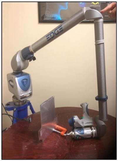
Figure 1.
3D Laser scanning of microchannel cold plate used for cooling the lithium-ion battery.
2.2. Experiments and Heat Flux Placement
The testing set-up utilized for LIB testing is explained in detail in our previously published paper [38]. The only difference is, in this paper, we used a different cold plate with different configuration. Three heat flux sensors from Omega company were put on the principal surface of the LIB (one close to the anode, one close to the cathode, and one close to the mid body) and the values were used for simulation. The heat flux sensor location is shown in Figure 2. A prismatic LIB pouch-type battery cell utilized for the testing and correspondingly for the model assessment is presented in Table 1, with technical details.
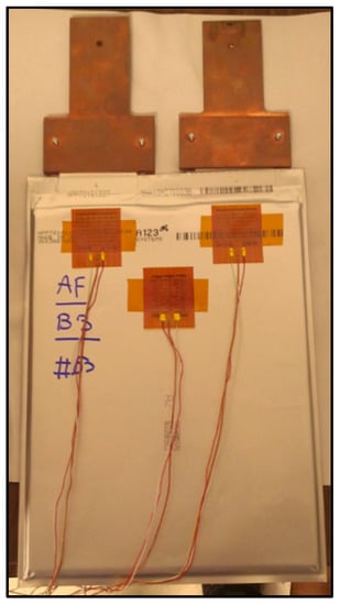
Figure 2.
Heat flux sensor locations.

Table 1.
Specifications of battery used for testing and modeling.
2.3. Testing Procedure
In the testing, four distinctive H2O inlet temperatures were preferred for the liquid coolant: 35 °C, 25 °C, 15 °C, and 5 °C. Two particular constant currents were chosen: 20 A and 40 A. The charge current (CC-CV: constant current-constant voltage) was 20 A. The testing methodology is shown in Table 2. The experimental conduct and experimental uncertainty are available in our previously published paper [38]. The reason for selecting 20 A and 40 A is that the heat generation from the battery cell is higher at these current rates.

Table 2.
Test plan.
3. Numerical Modeling
3.1. Governing Equations
For numerical work, the stream within the micro-cooling plates is turbulent and, hence, for the turbulence model, STAR CCM+ is utilized. The Reynolds number is calculated to find out the flow pattern, whether it is turbulent or laminar, and is presented as described in Equation (1).
where is the average liquid speed (m/s), is the characteristic length (m), is the dynamic liquid viscosity (Ns/m2), is the kinematic liquid viscosity (m2/s), also given as , and is the liquid density (kg/m3). The movement from laminar to turbulent stream relies on flow pattern. The transition happens at the Reynolds number between 105 and 106 for the flow over a flat plate. For flows in round channels, the critical Reynolds number is between 2000 and 3000. In this study, = 8.7 × 10³ and, furthermore, the stream in this manner is turbulent. The Reynolds-averaged Navier–Stokes (RANS)-based modeling approach, which averages the stream amounts for a whole limit of sizes of the turbulence being demonstrated, was utilized. The governing equations are:
where u is the speed (m/s), is the gradient operator, is the mean speed (m/s), is the Reynold’s stress, is the pressure (Pa), is the Prandtl number, and is the turbulent Prandtl number. Now the stream is considered turbulent; then, an appropriate turbulence model is required. In this examination, the realizable k-ε turbulence model was utilized, given the robustness of the model, reasonable precision for an extensive variety of streams, and demonstrated ability in heat exchange and stream investigation. The turbulent kinetic energy and eddy viscosity equations are as follows [39]:
In the above conditions, is the production of turbulence K.E. because of the buoyancy and gives the production of turbulence K.E. because of the average speed slops. presents the contribution of the fluctuating dilatation in compressible turbulence to the general dissipation rate. , , and are the constants, and are the turbulent Prandtl numbers for and , individually. and are user-defined source terms. The turbulent (or eddy) viscosity is processed by joining and as follows:
where is a constant. , , , , and have default values of 1.44, 1.92, 0.09, 1.0, and 1.3.
3.2. Geometry and Boundary Conditions
The full geometry of the cold plate utilized for LIB cooling in DEP MeshWroks 8.0 is given in Figure 3 and Figure 4.
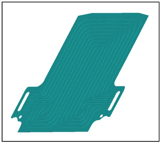
Figure 3.
CAD image after 3D laser scanning.
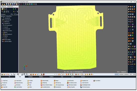
Figure 4.
DEP MeshWorks 8.0 screenshot during meshing of cold plate.
In a CFD, the word “wall” alludes to any rigid face that the stream may not infiltrate and, in this manner, incorporates the walls, the ground, and faces of the tested battery. The accompanying specifications are chosen for the model advancement:
3.2.1. Coolant Water
- (1)
- The stream is viewed as steady state, incompressible, and turbulent,
- (2)
- Water is picked as the flowing liquid,
- (3)
- Mass flow rate at each channel = 0.000277677 kg/s,
- (4)
- Total mass flow rate at all nine channels = 0.002499003 kg/s,
- (5)
- Area at each channel = 5.272 × 10⁻⁷ m2,
- (6)
- Density = 997.56 kg/m3,
- (7)
- Dynamic viscosity = 0.00088871 Pa-s,
- (8)
- The specific heat = 4181.72 J/kg-K,
- (9)
- Conductivity (thermal) = 0.62 W/m-K,
- (10)
- Turbulent Prandtl number = 0.9.
3.2.2. Outlet Cover-Aluminum
- (1)
- Specific heat = 903 J/kg-K,
- (2)
- Density = 2702 kg/m3,
- (3)
- Conductivity (thermal) = 237 W/m-K.
3.2.3. Volume Mesh Details (STAR CCM+)
- (1)
- Mesh type = polyhedral mesh and prism layer mesh,
- (2)
- Base size = 2 mm,
- (3)
- Number of prism layers = 2,
- (4)
- Thickness of prism layer = 0.3 mm,
- (5)
- Stretching of the prism layer = 1,
- (6)
- Growth factor for polyhedral mesh = 1.
3.2.4. Model Set-Up
- (1)
- Time: steady state,
- (2)
- Flow: turbulent,
- (3)
- Fluid: incompressible fluid,
- (4)
- Turbulence model: Realizable K-Epsilon (RANS),
- (5)
- Wall treatment: two-layer all y+ wall treatment (y+ ≈ 5),
- (6)
- Solver: segregated,
- (7)
- Convection: second-order,
- (8)
- Turbulence intensity: 0.01 (default),
- (9)
- Turbulent viscosity ratio: 10.0 (default).
3.3. Meshing in DEP MeshWorks 8.0
The meshing of the space is a vital part for different parameters of meshing, for example, quality criteria, mesh size, the node numbers, and the pattern of the components significantly affected the exactness of the outcomes and the numerical conduct of the result. Here, the meshing is also conducted using DEP MeshWorks 8.0 software. The screenshot of DEP MeshWorks during meshing of the cold plate is shown in Figure 4. Meshing in all nine inlet channels of the cold plate is also shown and the meshing in the top portion of the cold plate, which is specifically designed for this prismatic battery cooling, is shown in Figure 5, which provides maximum cooling in this region because of the higher heat generation being near electrodes. Meshing in inlet channels in DEP MeshWorks 8.0 is also shown in Figure 6.

Figure 5.
Meshing in all nine inlet channels and top side of cold plates in DEP MeshWorks 8.0.
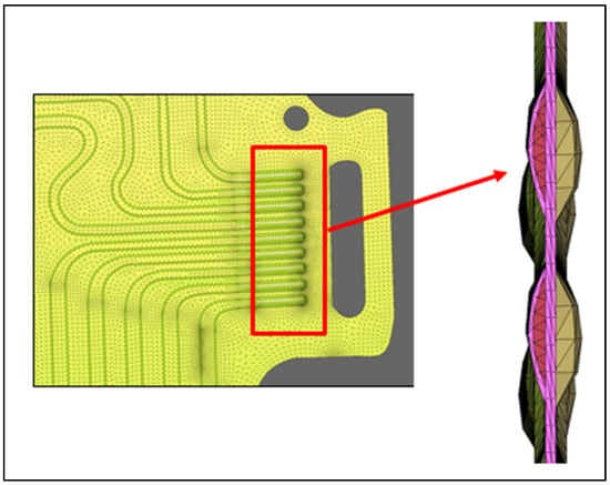
Figure 6.
Meshing in inlet channels in DEP MeshWorks 8.0.
4. Analysis
This part demonstrates the outcomes acquired from a prismatic LIB, at a wide variety of currents of 20 A and 40 A for fluid (water) cooling at ambient temperatures of 5 °C, 15 °C, 25 °C, and 35 °C.
4.1. Temperature Fields during 20 A
The temperature contours acquired from STAR CCM+ CFD at a release current of 20 A and 5 °C, 15 °C, 25 °C, and 35 °C working conditions (fluid cooling) are presented in Figure 7, Figure 8, Figure 9 and Figure 10. To remind readers, three heat flux devices were situated on the surface of the LIB: the first was situated close to the positive tab or cathode, the second was situated close to the negative tab or anode, and the third was situated close to the central part of the LIB cell. Figure 7 shows the simulation results at 20 A releasing current and 5 °C coolant inlet temperature, with heat flux values at position 1 = 575.5 W/m2, position 2 = 599.3 W/m2, and position 3 = 149.4 W/m2. Similarly, Figure 8 shows temperature contours at 20 A releasing current and 15 °C coolant inlet temperature, with heat flux at position 1 = 475.7 W/m2, position 2 = 781.4 W/m2, and position 3 = 157.9 W/m2. It is found that the temperature contours are almost the same with the inlet being cold and outlet being hot. Figure 9 shows temperature fields at 20 A releasing current and 25 °C coolant inlet temperature, with heat flux at position 1 = 148.2 W/m2, position 2 = 168.9 W/m2, and position 3 = 74.4 W/m2. Figure 10 shows temperature contours at 20 A releasing current and 35 °C coolant inlet temperature, with heat flux at position 1 = 47.6 W/m2, position 2 = 86.1 W/m2, and position 3 = 25.2 W/m2.
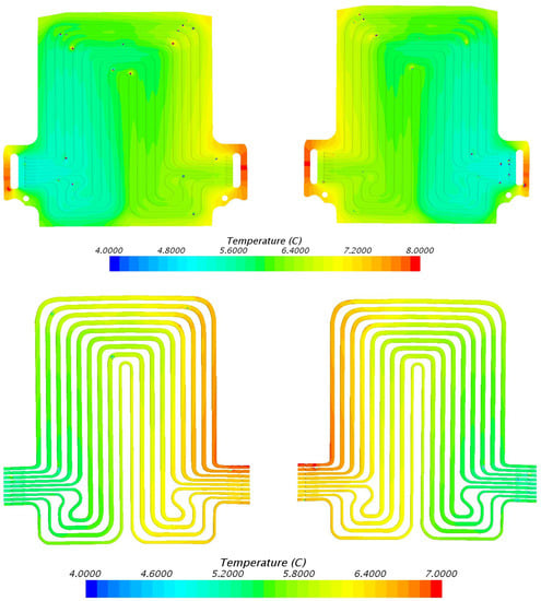
Figure 7.
Temperature field at 20 A discharge current and 5 °C coolant inlet temperature with heat flux at position 1 = 575.5 W/m2, position 2 = 599.3 W/m2, and position 3 = 149.4 W/m2.
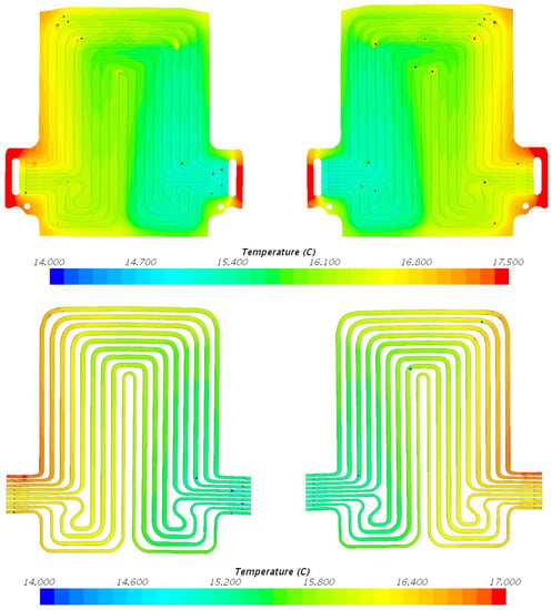
Figure 8.
Temperature field at 20 A discharge current and 15 °C coolant inlet temperature with heat flux at position 1 = 475.7 W/m2, position 2 = 781.4 W/m2, and position 3 = 157.9 W/m2.
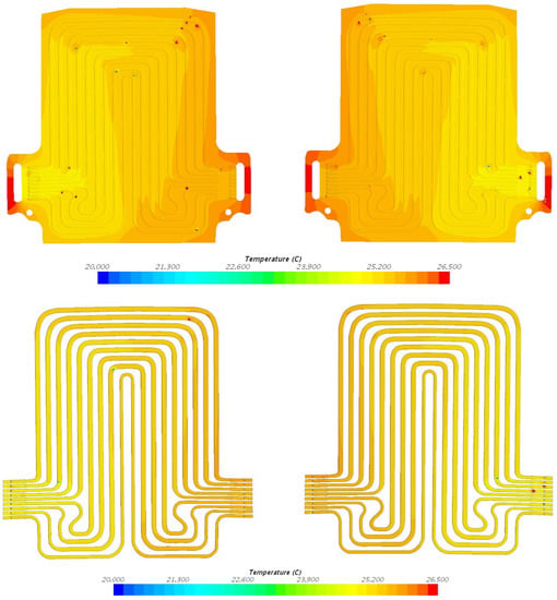
Figure 9.
Temperature field at 20 A discharge current and 25 °C coolant inlet temperature with heat flux at position 1 = 148.2 W/m2, position 2 = 168.9 W/m2, and position 3 = 74.4 W/m2.
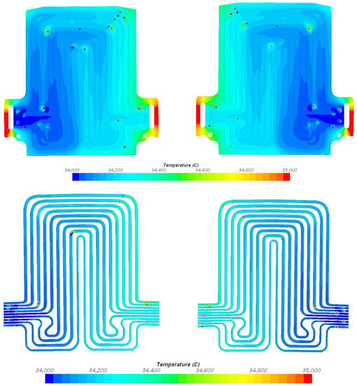
Figure 10.
Temperature field at 20 A discharge current and 35 °C coolant inlet temperature with heat flux at position 1 = 47.6 W/m2, position 2 = 86.1 W/m2, and position 3 = 25.2 W/m2.
It is discovered that the most elevated estimation of coolant outlet temperature is 35.72 °C for 40 A-35 °C (case) and the lowest estimation is 6.5726 °C for 20 A-5 °C (case) obtained from STAR CCM+. It is seen that there is an incredible effect of working temperature on the execution of battery and coolant plates and as the working temperature incrementally changes between 5 °C and 35 °C for a specific release current of 20 A, the temperature field data are also incrementally changing. The overall cooling designs are the equivalent, demonstrating more noteworthy temperature contracts at the inner part of the coolant plate where the water is coolest. The temperatures differ with the inlet temperature; however, the general coolant diagram stays generally similar. This is possible because of the lower temperature values included. The coolant diagrams pursue what is detected on the LIB testing, with the exit being high as compared to the inlet. Table 3 shows the fluid inlet and exit temperature at 20 A releasing current and distinctive working temperature scenarios of 5 °C, 15 °C, 25 °C, and 35 °C. Table 3, likewise, provides the difference in experimental and simulated values obtained from STAR CCM+ software. It is additionally seen that the simulated data are higher than experimental values from Table 3.

Table 3.
Water inlet and water outlet temperature at 20 A and 40 A releasing currents and at various operating temperatures.
4.2. Temperature Fields during 40 A
Figure 11 shows temperature fields at 40 A releasing current and 5 °C coolant inlet temperature, with heat flux at position 1 = 1294.5 W/m2, position 2 = 1390.8 W/m2, and position 3 = 341.3 W/m2. Figure 12 shows temperature contours at 40 A releasing current and 15 °C coolant inlet temperature, with heat flux at position 1 = 1029.7 W/m2, position 2 = 1509.9 W/m2, and position 3 = 331.7 W/m2. Figure 13 shows temperature contours at 40 A releasing current and 25 °C coolant inlet temperature, with heat flux at position 1 = 684.9 W/m2, position 2 = 733.2 W/m2, and position 3 = 194.8 W/m2. Figure 14 shows temperature contours at 40 A releasing current and 35 °C coolant inlet temperature, with heat flux at position 1 = 585.6 W/m2, position 2 = 689.7 W/m2, and position 3 = 163.3 W/m2. It is seen that as the battery releases, the moving fluid within the cooling plates becomes warm; this is self-evident. As the release current increments between 20 A and 40 A, there is also an increment in temperature data. The pattern noticed is that increments in release rates and increments in ambient temperatures result in increments in temperature within the coolant plates. Table 3 illustrates the summary of water inlet and outlet temperature at 40 A releasing current and different operating temperature conditions of 5 °C, 15 °C, 25 °C, and 35 °C. Table 3 also provides the difference in experimental and simulated values obtained from STAR CCM+ software and it is found that the modeled data are higher than experimental data. Once more, the general cooling designs are the equivalent, like the outcomes in Section 4.1. There are noteworthy temperature contrasts at the entrance of the coolant plate when the fluid is cooler. The temperature data change with the change in inlet temperatures; however, the general diagram remains the same.
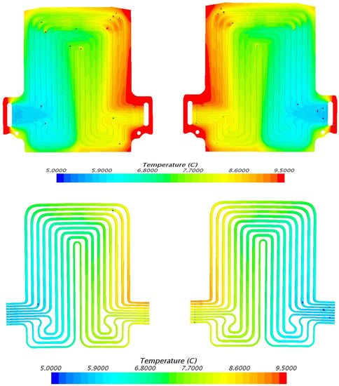
Figure 11.
Temperature field at 40 A discharge current and 5 °C coolant inlet temperature, with heat flux at position 1 = 1294.5 W/m2, position 2 = 1390.8 W/m2, and position 3 = 341.3 W/m2.
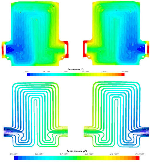
Figure 12.
Temperature field at 40 A discharge current and 15 °C coolant inlet temperature, with heat flux at position 1 = 1029.7 W/m2, position 2 = 1509.9 W/m2, and position 3 = 331.7 W/m2.
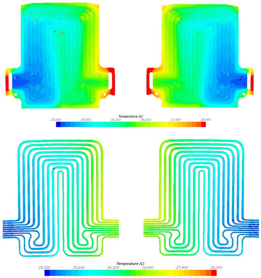
Figure 13.
Temperature field at 40 A discharge current and 25 °C coolant inlet temperature, with heat flux at position 1 = 684.9 W/m2, position 2 = 733.2 W/m2, and position 3 = 194.8 W/m2.
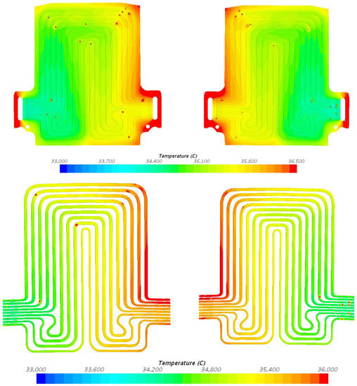
Figure 14.
Temperature field at 40 A discharge current and 35 °C coolant inlet temperature, with heat flux at position 1 = 585.6 W/m2, position 2 = 689.7 W/m2, and position 3 = 163.3 W/m2.
4.3. Velocity Contours at 20 A and 40 A Releasing Currents
The velocity shapes at 20 A and 40 A releasing currents and 5 °C, 15 °C, 25 °C, and 35 °C working temperatures appear in Figure 15 and Figure 16 for all nine numbers of channels. It is found that the velocity shapes are indistinguishable in every case; this is normal, given the lower temperatures engaged with the models that would have practically no impact on the water density. Such outcomes might be influenced by the lower value of y+, wall functions, and utilized model (turbulence). It is additionally seen that the speed distribution at the inner and outer areas is with curved flow paths with relatively higher velocity gradients.
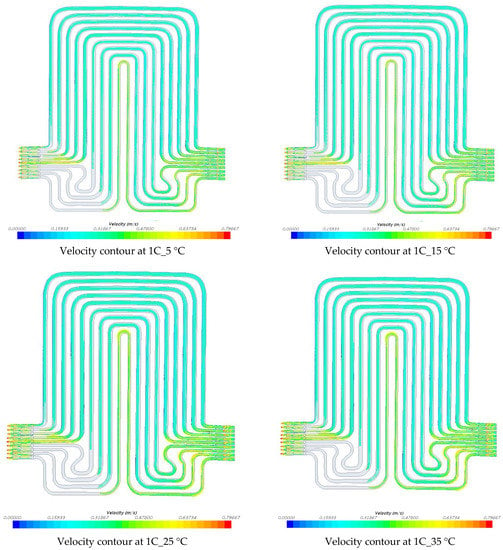
Figure 15.
Velocity distribution at 20 A discharge current and 5 °C, 15 °C, 25 °C, and 35 °C coolant inlet temperature.
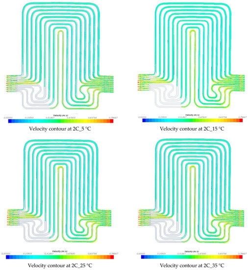
Figure 16.
Velocity distribution at 40 A discharge current and 5 °C, 15 °C, 25 °C, and 35 °C coolant inlet temperature.
4.4. Transient Temperature Profiles of Water Flow and Voltage Distributions
Figure 17 and Figure 18 show the transient pattern of water streaming within the coolant plates at 20 A and 40 A constant current releasing rates, with diverse working temperatures of 5 °C, 15 °C, 25 °C, and 35 °C. As explained before, this increment in temperature is because of the joule heating () from the LIB during discharges. Moreover, the impact of releasing current on the battery electrical execution is, likewise, examined and we discovered that there is an incredible impact from both releasing current and the working temperatures on the battery execution. At low releasing currents, the battery capacity remains nearer to the supplier’s details, yet as releasing current increments, there is a decrease in the releasing capacity. Notwithstanding the ambient temperature difference from 35 °C to 5 °C, there is a more prominent decrease in the releasing capacity. In general, it is observed that the incremented releasing currents and diminished ambient temperatures output the decline release capacity. These effects (reduction in battery discharge capacity) can be seen in Figure 19 and Figure 20, which present the discharge/charge profiles at 60A and 80A constant current discharges (and charge current being 20 A), with various working temperatures of 5 °C, 15 °C, 25 °C, and 35 °C.
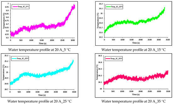
Figure 17.
Transient temperature profile of water flow at 20 A with 5 °C, 15 °C, 25 °C, and 35 °C.


Figure 18.
Transient temperature profile of water flow at 40 A with 5 °C, 15 °C, 25 °C, and 35 °C.
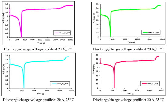
Figure 19.
Discharge/charge voltage profile at 20 A with 5 °C, 15 °C, 25 °C, and 35 °C.


Figure 20.
Discharge/charge voltage profile at 40 A with 5 °C, 15 °C, 25 °C, and 35 °C.
5. Conclusions
The paper presented a method for modeling the thermal execution of a microchannel coolant plate used to cool an EV battery cell and compared with experimental results. We presented a numerical model using STAR CCM+ for CFD simulation and the temperature and velocity contours were reported at lower currents of 20 A and 40 A and diverse working fluid (water) temperatures, with 5 °C, 15 °C, 25 °C, and 35 °C. Some concluding comments are expressed as follows:
- (i)
- The temperature fields inside the microchannel coolant plates increased as the discharge current increased between 20 A and 40 A;
- (ii)
- Incremental releasing currents resulted in increments in the heat flux at three assigned points on the LIB surface;
- (iii)
- The heat flux measuring devices nearest to the tabs provided higher values than the middle heat flux measuring devices. The coolant diagrams from the models were predictable with those received from testing;
- (iv)
- The simulated values obtained from STAR CCM+ were higher than the experimental values;
- (v)
- The velocity distribution was uniform for all cases, except at the inlet and outlet with curved flow paths with relatively higher velocity gradients.
These outcomes provide insights into the outline and advancement of LIB systems for auto cars.
Author Contributions
Conceptualization, S.P., K.G. and R.F.; methodology, S.P., K.G. and K.P.; software, K.G. and M.S.H.; validation, S.P. and M.S.H.; formal analysis, S.P., K.G. and M.-K.T.; investigation, S.P. and M.S.H.; resources, K.G. and M.F.; data curation, S.P.; writing—original draft preparation, S.P. and M.-K.T.; writing—review and editing, M.S.H. and K.P.; visualization, S.P. and M.S.H.; supervision, R.F. and M.F.; project administration, R.F. and M.F. All authors have read and agreed to the published version of the manuscript.
Funding
This research received no external funding.
Institutional Review Board Statement
Not applicable.
Informed Consent Statement
Not applicable.
Data Availability Statement
The data presented in this study are available on request from the corresponding author. The data are not publicly available due to confidentiality.
Conflicts of Interest
The authors declare no conflict of interest.
Nomenclature
| model constants | |
| constant | |
| C | Potential or voltage [V] |
| generation of turbulence kinetic energy due to mean velocity gradients & buoyancy | |
| I | current [A] |
| turbulent kinetic energy (J) | |
| characteristic dimension (m) | |
| Prandtl number and Turbulent Prandtl number | |
| pressure (Pa) | |
| Re | Reynold’s number |
| user-defined source terms | |
| T | temperature [°C or K] |
| τ | time [s] |
| t | time [s] |
| u | speed (m/s) |
| mean fluid velocity (m/s) | |
| average velocity (m/s) | |
| turbulent eddy frequency (1/s) | |
| y+ | wall treatment |
| the contribution of the oscillating dilatation in compressible turbulence to the general dissipation rate | |
| density (kg/m3) | |
| gradient operator | |
| dynamic fluid viscosity (Ns/m2) | |
| Reynold’s stress | |
| kinematic fluid viscosity (m2/s) | |
| turbulent Prandtl numbers for and | |
| sim | simulated |
| act | actual |
| + | Related to wall treatment |
| ° | degree |
| Ah | Ampere-hour |
| ANSYS Inc. | American Computer-aided engineering software developer |
| BTMS | Battery thermal management system |
| C | Capacity |
| CC | Constant-current |
| CV | Constant-voltage |
| CT | Computed tomography |
| CAD | Computer aided design |
| CFD | Computational fluid dynamics |
| DEP | Detroit Engineered Products, Inc. |
| CPU | Computer user memory |
| EV or BEV | Electric vehicle or battery-operated electric vehicle |
| FEM | Finite element method |
| FCV | Fuel cell vehicle |
| FSP | Field synergy principle |
| HEV | Hybrid electric vehicle |
| K.E. | Kinetic energy |
| LiMn2O4 | Lithium manganese oxide |
| LiMnNiCOO2 | Lithium manganese cobalt oxide |
| LiFePO4 | Lithium iron phosphate |
| LIB | Lithium-ion batteries |
| LES | Large eddy simulation |
| LED | Light-emitting diode |
| MeshWorks | Software used for mesh generation and CAD |
| PC | Personal computer |
| PCM | Phase change material |
| PHEV | Plug-In hybrid electric vehicle |
| RE | Reverse engineering |
| RNG | Renormalization group |
| RSM | Reynold’s stress model |
| RANS | Reynolds-averaged Navier-Stokes |
| SST | Shear stress transport |
| SLPB | Superior lithium polymer battery |
| STAR CCM+ | Simulation of Turbulent flow in Arbitary Regions-Computational Continuum Mechanics + (C++ based) |
| US06 | United States 06 drive cycle |
| 2D | Two-dimensional |
| 3D | Three-dimensional |
| 18650 | IFR 18650 cylindrical battery (“I” is for Lithium-ion rechargeable, “F” is for the component “Fe” that is Iron, “R” is for the round cell, 18650 means diameter of 1.8 cm and 650 means the height is 6.5 cm) |
References
- Wang, Q.; Sun, Q.; Ping, P.; Zhao, X.; Sun, J.; Lin, Z. Heat transfer in the dynamic cycling of lithium–titanate batteries. Int. J. Heat Mass Transf. 2016, 93, 896–905. [Google Scholar] [CrossRef]
- Tran, M.-K.; Akinsanya, M.; Panchal, S.; Fraser, R.; Fowler, M. Design of a Hybrid Electric Vehicle Powertrain for Performance Optimization Considering Various Powertrain Components and Configurations. Vehicles 2021, 3, 20–32. [Google Scholar] [CrossRef]
- Ritchie, A.; Howard, W. Recent developments and likely advances in lithium-ion batteries. J. Power Sources 2006, 162, 809–812. [Google Scholar] [CrossRef]
- Ye, Y.; Saw, L.H.; Shi, Y.; Tay, A.A. Numerical analyses on optimizing a heat pipe thermal management system for lithium-ion batteries during fast charging. Appl. Therm. Eng. 2015, 86, 281–291. [Google Scholar] [CrossRef]
- Tran, M.-K.; Fowler, M. A Review of Lithium-Ion Battery Fault Diagnostic Algorithms: Current Progress and Future Challenges. Algorithms 2020, 13, 62. [Google Scholar] [CrossRef] [Green Version]
- Tran, M.-K.; Mevawalla, A.; Aziz, A.; Panchal, S.; Xie, Y.; Fowler, M. A Review of Lithium-Ion Battery Thermal Runaway Modeling and Diagnosis Approaches. Processes 2022, 10, 1192. [Google Scholar] [CrossRef]
- Tran, M.-K.; Mathew, M.; Janhunen, S.; Panchal, S.; Raahemifar, K.; Fraser, R.; Fowler, M. A comprehensive equivalent circuit model for lithium-ion batteries, incorporating the effects of state of health, state of charge, and temperature on model parameters. J. Energy Storage 2021, 43, 103252. [Google Scholar] [CrossRef]
- Tran, M.-K.; Bhatti, A.; Vrolyk, R.; Wong, D.; Panchal, S.; Fowler, M.; Fraser, R. A Review of Range Extenders in Battery Electric Vehicles: Current Progress and Future Perspectives. WEVJ 2021, 12, 54. [Google Scholar] [CrossRef]
- Tran, M.-K.; DaCosta, A.; Mevawalla, A.; Panchal, S.; Fowler, M. Comparative Study of Equivalent Circuit Models Performance in Four Common Lithium-Ion Batteries: LFP, NMC, LMO, NCA. Batteries 2021, 7, 51. [Google Scholar] [CrossRef]
- Panchal, S.; Mathewson, S.; Fraser, R.; Culham, R.; Fowler, M. Thermal Management of Lithium-Ion Pouch Cell with Indirect Liquid Cooling Using Dual Cold Plates Approach. SAE Int. 2015, 4, 1–15. [Google Scholar] [CrossRef]
- Tran, M.-K.; Cunanan, C.; Panchal, S.; Fraser, R.; Fowler, M. Investigation of Individual Cells Replacement Concept in Lithium-Ion Battery Packs with Analysis on Economic Feasibility and Pack Design Requirements. Processes 2021, 9, 2263. [Google Scholar] [CrossRef]
- Tran, M.-K.; Panchal, S.; Khang, T.D.; Panchal, K.; Fraser, R.; Fowler, M. Concept Review of a Cloud-Based Smart Battery Management System for Lithium-Ion Batteries: Feasibility, Logistics, and Functionality. Batteries 2022, 8, 19. [Google Scholar] [CrossRef]
- Wang, C.H.; Lin, T.; Huang, J.T.; Rao, Z.H. Temperature response of a high power lithium-ion battery subjected to high current discharge. Mater. Res. Innov. 2015, 19, S2-156. [Google Scholar] [CrossRef]
- Panchal, S.; Dincer, I.; Agelin-Chaab, M.; Fowler, M.; Fraser, R. Uneven temperature and voltage distributions due to rapid discharge rates and different boundary conditions for series-connected LiFePO 4 batteries. Int. Commun. Heat Mass Transf. 2017, 81, 210–217. [Google Scholar] [CrossRef]
- Teng, H.; Ma, Y.; Yeow, K.; Thelliez, M. An Analysis of a Lithium-ion Battery System with Indirect Air Cooling and Warm-Up. SAE Int. J. Passeng. Cars—Mech. Syst. 2011, 4, 1343–1357. [Google Scholar] [CrossRef]
- He, F.; Ma, L. Thermal Management in Hybrid Power Systems Using Cylindrical and Prismatic Battery Cells. Heat Transf. Eng. 2015, 37, 581–590. [Google Scholar] [CrossRef]
- Giuliano, M.R.; Prasad, A.K.; Advani, S.G. Experimental study of an air-cooled thermal management system for high capacity lithium–titanate batteries. J. Power Sources 2012, 216, 345–352. [Google Scholar] [CrossRef]
- Jin, L.; Lee, P.; Kong, X.; Fan, Y.; Chou, S. Ultra-thin minichannel LCP for EV battery thermal management. Appl. Energy 2013, 113, 1786–1794. [Google Scholar] [CrossRef]
- Lin, C.; Xu, S.; Chang, G.; Liu, J. Experiment and simulation of a LiFePO4 battery pack with a passive thermal management system using composite phase change material and graphite sheets. J. Power Sources 2015, 275, 742–749. [Google Scholar] [CrossRef]
- Wang, Q.; Jiang, B.; Li, B.; Yan, Y. A critical review of thermal management models and solutions of lithiumion batteries for the development of pure electric vehicles. Renew. Sustain. Energy Rev. 2016, 64, 106–128. [Google Scholar] [CrossRef]
- Koca, F.; Zabun, M. The effect of outlet location on heat transfer performance in micro pinfin cooling used for a CPU. Eur. Phys. J. Plus 2021, 136, 1–15. [Google Scholar] [CrossRef]
- Zhao, Y.; Akolekar, H.D.; Weatheritt, J.; Michelassi, V.; Sandberg, R.D. RANS turbulence model development using CFD-driven machine learning. J. Comput. Phys. 2020, 411, 109413. [Google Scholar] [CrossRef] [Green Version]
- Vyroubal, P.; Kazda, T.; Maxa, J.; Vondrák, J. Analysis of Temperature Field in Lithium Ion Battery by Discharging. ECS Trans. 2015, 70, 269–273. [Google Scholar] [CrossRef]
- Yeow, K.; Teng, H.; Thelliez, M.; Tan, E. Thermal Analysis of a Li-ion Battery System with Indirect Liquid Cooling Using Finite Element Analysis Approach. SAE Int. J. Altern. Powertrains 2012, 1, 65–78. [Google Scholar] [CrossRef]
- Jarrett, A.; Kim, I.Y. Design optimization of electric vehicle battery cooling plates for thermal performance. J. Power Sources 2011, 196, 10359–10368. [Google Scholar] [CrossRef]
- Deng, T.; Zhang, G.; Ran, Y. Study on thermal management of rectangular Li-ion battery with serpentine-channel cold plate. Int. J. Heat Mass Transf. 2018, 125, 143–152. [Google Scholar] [CrossRef]
- Mondal, B.; Lopez, C.F.; Verma, A.; Mukherjee, P.P. Vortex generators for active thermal management in lithium-ion battery systems. Int. J. Heat Mass Transf. 2018, 124, 800–815. [Google Scholar] [CrossRef]
- De Vita, A.; Maheshwari, A.; Destro, M.; Santarelli, M.; Carello, M. Transient thermal analysis of a lithium-ion battery pack comparing different cooling solutions for automotive applications. Appl. Energy 2017, 206, 101–112. [Google Scholar] [CrossRef]
- Cooper, S.; Eastwood, D.; Gelb, J.; Damblanc, G.; Brett, D.; Bradley, R.; Withers, P.; Lee, P.; Marquis, A.; Brandon, N.; et al. Image based modelling of microstructural heterogeneity in LiFePO 4 electrodes for Li-ion batteries. J. Power Sources 2013, 247, 1033–1039. [Google Scholar] [CrossRef]
- Basu, S.; Hariharan, K.S.; Kolake, S.M.; Song, T.; Sohn, D.K.; Yeo, T. Coupled electrochemical thermal modelling of a novel Li-ion battery pack thermal management system. Appl. Energy 2016, 181, 1–13. [Google Scholar] [CrossRef]
- Mohammadian, S.; He, Y.L.; Zhang, Y. Internal cooling of a lithium-ion battery using electrolyte as coolant through microchannels embedded inside the electrodes. J. Power Sources 2015, 293, 458–466. [Google Scholar] [CrossRef]
- Al-Zareer, M.; Dincer, I.; Rosen, M.A. Heat transfer modeling of a novel battery thermal management system. Numer. Heat Transf. Part A Appl. 2018, 73, 277–290. [Google Scholar] [CrossRef]
- Li, X.; He, F.; Ma, L. Thermal management of cylindrical batteries investigated using wind tunnel testing and computational fluid dynamics simulation. J. Power Sources 2013, 238, 395–402. [Google Scholar] [CrossRef]
- Jassem, R.R.; Salem, T.K. An Experimental and Numerical Study the Performance of Finned liquid Cold-Plate with Different Operating Conditions. Int. J. Recent Res. Rev. 2016, 9, 2277–2283. [Google Scholar]
- Jiaqiang, E.; Xu, S.; Deng, Y.; Zhu, H.; Zuo, W.; Wang, H.; Chen, J.; Peng, Q.; Zhang, Z. Investigation on thermal performance and pressure loss of the fluid cold-plate used in thermal management system of the battery pack. Appl. Therm. Eng. 2018, 145, 552–568. [Google Scholar] [CrossRef]
- Panchal, S.; Khasow, R.; Dincer, I.; Agelin-Chaab, M.; Fraser, R.; Fowler, M. Numerical modeling and experimental investigation of a prismatic battery subjected to water cooling. Numer. Heat Transf. Part A Appl. 2017, 71, 626–637. [Google Scholar] [CrossRef]
- Panchal, S.; Gudlanarva, K.; Tran, M.-K.; Fraser, R.; Fowler, M. High Reynold’s Number Turbulent Model for Micro-Channel Cold Plate Using Reverse Engineering Approach for Water-Cooled Battery in Electric Vehicles. Energies 2020, 13, 1638. [Google Scholar] [CrossRef] [Green Version]
- Panchal, S.; Dincer, I.; Agelin-Chaab, M.; Fraser, R.; Fowler, M. Design and simulation of a lithium-ion battery at large C-rates and varying boundary conditions through heat flux distributions. Measurement 2017, 116, 382–390. [Google Scholar] [CrossRef] [Green Version]
- ANSYS, Inc. ANSYS Fluent Advanced Add-On Modules. Available online: http://www.ansys.com (accessed on 1 October 2020).
Publisher’s Note: MDPI stays neutral with regard to jurisdictional claims in published maps and institutional affiliations. |
© 2022 by the authors. Licensee MDPI, Basel, Switzerland. This article is an open access article distributed under the terms and conditions of the Creative Commons Attribution (CC BY) license (https://creativecommons.org/licenses/by/4.0/).