Article

Research on Electric Vehicle Electromagnetic Protection Considering Radiation of Two Wireless Chargers

1
Institute of Railway Technology, Lanzhou Jiaotong University, Lanzhou 730070, China
2
Key Laboratory of Opto-Electranic Technology and Intelligent Control, Ministry of Education, Lanzhou Jiaotong University, Lanzhou 730070, China
*
Author to whom correspondence should be addressed.
World Electr. Veh. J. 2022, 13(6), 95; https://doi.org/10.3390/wevj13060095
Submission received: 2 May 2022 / Revised: 22 May 2022 / Accepted: 24 May 2022 / Published: 26 May 2022

Abstract

:
To evaluate the electromagnetic exposure safety of multiple wireless charging vehicles charging simultaneously and explore simple, effective electromagnetic protection methods, in this paper, car model, wireless charger model, and human body models were established by using COMSOL Multiphysics software. The influence of different relative positions of two wireless chargers on magnetic induction strength (B) in simulation space when two cars are charging simultaneously and the influence of different car body materials on a driver’s body surface B and internal induced electric field strength (E) were analyzed. The simulation results showed that the maximum value of B in the car when two wireless chargers work simultaneously was 1.30 times that when a single wireless charger works. The maximum value of simulation space B could be reduced by 24.23% by staggering the front and rear positions of the two wireless chargers. The use of aluminum alloy car body could reduce the maximum value of human body surface B of the driver in the car by 99.76%. The B of the driver’s body surface in the aluminum alloy car body combined with the staggering method of two chargers was the smallest, which was 42.86% of that when the two chargers were not staggered, and its electromagnetic exposure level was 1.33% of the International Commission on Non-Ionizing Radiation Protection public exposure limit. The results showed that the protection method is effective.

1. Introduction

The requirements of unmanned aerial vehicle and electric vehicle (EV) automatic driving technology for endurance capability are increasing; the development of wireless power transfer (WPT) technology has eased some pressure [1,2,3]. With the development of EV wireless charging technology, fast charging has increased the power level of the WPT system from 3.7 kW to 22 kW [4,5]; the charging simultaneously produces a larger electromagnetic leakage, triggering scholars to discuss the safety of its electromagnetic environment.
In terms of the electromagnetic exposure safety assessment of wireless charging EVs, reference [6] discussed the accuracy and efficiency of numerical dose simulation when the human body is exposed to the electrostatic induction charging system of EV. To improve the transmission efficiency and stability of EVs, reference [7] developed a wireless charging system for EVs using superconducting resonant coils and ordinary resonant coils, and determined the safety of electromagnetic exposure. Reference [8] evaluated the electromagnetic dosimetry of a 10 kW WPT system and proposed feasible electromagnetic protection measures. Reference [9] studied the electromagnetic exposure of the human body during static wireless charging of EVs; under extreme conditions, the reference limit exceeded the standard but met the basic limit. Reference [10] studied the effect of static magnetic field on the cognitive ability of EV drivers. The results showed that despite no substantial effect on cognitive ability, changes in electroencephalogram were remarkable. References [11,12] compared the influence of the chassis on the electromagnetic exposure of the EV WPT system; the results showed that under the shielding of carbon fiber chassis in the mid power band (85 kHz, 7.7 kW), the driving position conformed to the basic limit of the International Commission on Non-Ionizing Radiation Protection (ICNIRP) but exceeded the reference limit, which proves that the shielding performance of carbon fiber is poor, and a thin metal is suggested to reduce the magnetic field.
The problem of excessive electromagnetic radiation of EV wireless charging gradually causes scholars to explore ways to reduce electromagnetic radiation. Reference [13] enhanced coupling and shields eddy current losses by using annular aluminum plate and ferrite rod. To reduce electromagnetic field leakage and improve efficiency, reference [14] proposed a WPT system combining near-field near-zero permeability and negative-permeability metal materials. Reference [15] studied the optimization of a shielding structure composed of multiple active coils, which reduces the magnetic field in key areas without affecting electrical performance. To obtain a higher transmission efficiency, reference [16] proposed a layered DD coil structure; moreover, ferrite as an electromagnetic shielding material has better power and transmission efficiency, and cobalt iron material can produce a higher emission power. Reference [17] proposed a wheeled WPT system with magnetic coupler structure to solve the electromagnetic exposure problem caused by the air gap. Reference [18] proposed a passive shielding scheme for the receiving side, in which the receiving coil and the transmitting coil were inverted in series. Reference [19] compared electromagnetic, metal, and resonant reactive current-shielding technologies, and proved that resonant reactive current shielding has a low electromotive force, a reasonable system efficiency, and an acceptable charger weight.
The abovementioned research only considers the electromagnetic exposure of single wireless charging EV, but in practical engineering applications, multiple EVs in the wireless charging station are charged wirelessly simultaneously, and the magnetic flux leakage is greater than that of a single EV. Ref. [20] studied the magnetic leakage problem when two electric cars are charged simultaneously (3.7 kW, 85 kHz) and analyzed the influence of the phase difference of coil current on magnetic leakage; the literature focuses on low-power bands, and the problem of keeping magnetic flux leakage specifications within the ICNIRP limits at high power is not considered. The selection of car body materials and the relative position between wireless chargers also change the electromagnetic environment in the car [21]. Therefore, when analyzing the electromagnetic exposure problem of multiple wireless chargers charging simultaneously, limiting the electromagnetic environment inside electric cars within a safe level by considering the relative position of wireless chargers and the influence of car body materials has higher practical importance.
This paper took the wireless charger of magnetic coupling resonance (MCR) electric cars with high power of 22.46 kW and resonant frequency of 22 kHz as the research object. Based on the basic idea of electromagnetic metrology, using the field-circuit coupling method, and combined with engineering practice, the wireless chargers of two cars were used as the electromagnetic exposure source, the influence of the relative position of the two chargers and the setting of the car bodies with different materials on the electromagnetic environment in the simulation space and in the car were analyzed, and the electromagnetic exposure safety of the driver in the car after the car body material was combined with the staggering method of the front and rear positions of the two wireless chargers was evaluated. The remaining part of this paper is structured as follows: the second section is the establishment of simulation model, the third section is the analysis of simulation results, and the conclusions are given in the fourth section.

2. Establishment of Simulation Model

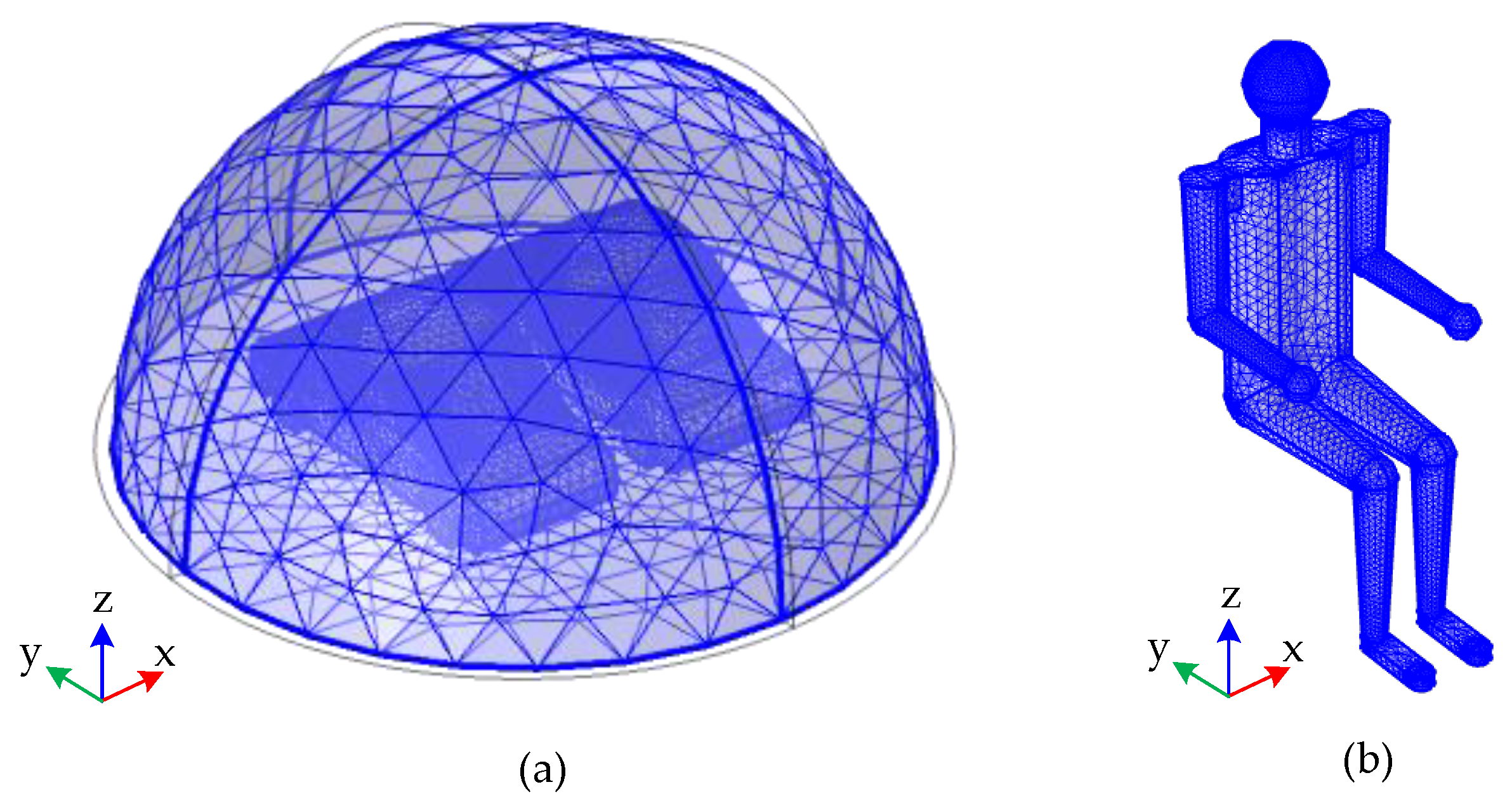
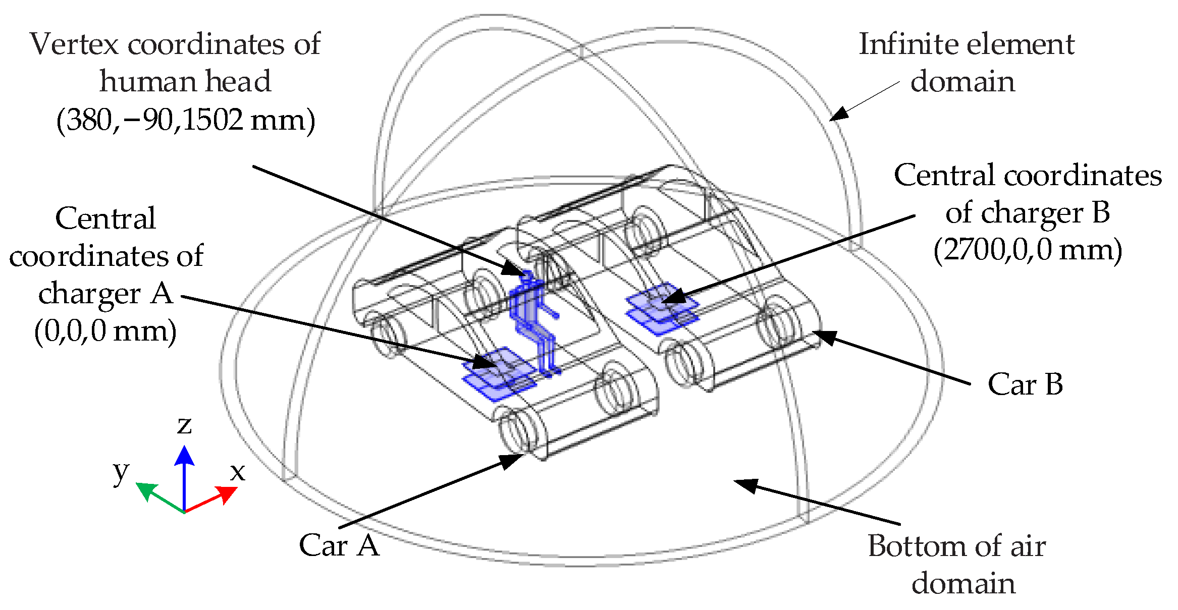
2.1. Global Model and Finite Element Discrete Model

The electromagnetic safety simulation model established in the finite element simulation software COMSOL Multiphysics 5.6 is shown in Figure 1, where the x direction is the width direction of the car, the y direction is along the parking space direction, and the z direction is the height direction of the car. Two electric cars, A and B, were parked side by side, and their wireless chargers are charger A and charger B, respectively. Considering the similarity of the electromagnetic environment of the human body in the two electric cars, only the electromagnetic exposure of the driver in car A is considered. The vertex coordinates of the driver’s body in car A were (380, −90, 1502 mm). The distance between the centers of the two wireless chargers was set to 2700 mm with reference to the width of the standard parking space. The central coordinates of wireless chargers A and B were (0, 0, and 0 mm) and (2700, 0, and 0 mm), respectively. The finite element discrete model is shown in Figure 2, where the wireless chargers and the human trunk adopt a relatively refined tetrahedral grid, with the minimum unit set to 8.4 and 0.4 mm, respectively. The human head adopts an ultra-fine tetrahedral mesh, and the minimum unit was set to 0.3 mm. The magnetic field module of COMSOL Multiphysics software is calculated in combination with the following formula:
  ×   H = J ,
B =   ×   A ,  
J = σ E + j ω D + σ v   ×   B + J e ,  
E = j ω A ,
In the formula, H (A/m) is the magnetic field strength, J (A/m2) is the current density, B (T) is the magnetic induction strength, A (Wb/m) is the magnetic vector potential, σ (S/m) is the conductivity, E (V/m) is the electric field strength, D (C/m2) is the electric flux density, v (m/s) is the speed, σv × B is the current generated when the conductor moves and cuts the magnetic field lines, and Je is the external current.

2.2. MCR Wireless Charger Model

The structure and size of wireless chargers A and B are identical, and both are composed of transmitting and receiving coils of the same size. The transmitting coil was on the ground of the parking space, the receiving coil was under the car chassis, and the air gap between the transmitting coil and the receiving coil was 190 mm. Ferrite with enhanced coupling was added outside the receiving coil and transmitting coil, with a relative permeability of 2300 and a thickness of 3 mm. The model parameters of the MCR wireless charger are shown in Table 1.

2.3. Car Body Model

Cars A and B have the same body size of 4310 mm × 1780 mm × 1520 mm; to facilitate mesh generation, the car body material was set to the average thickness of the whole vehicle parts of 1.3 mm. The detailed dielectric parameters of car body materials are shown in Table 2. The dielectric parameters of carbon fiber in the table were taken from literature [22].

2.4. Human Body Model

The human body model in the car was composed of head model and trunk model. The head model adopted a three-layer spherical head model. The height of the human body was 1750 mm, and the sitting height was 1302 mm. The relative permittivity and conductivity of tissues of each part of the human body calculated at the frequency of 22 kHz are shown in Table 3. The mean values of dry skin and wet skin were taken for the dielectric parameters of skin tissue in the table, and the mean values of cancellous bone, cortical bone, and bone marrow were taken for the dielectric parameters of bone tissue [23,24].

3. Analysis of Simulation Results

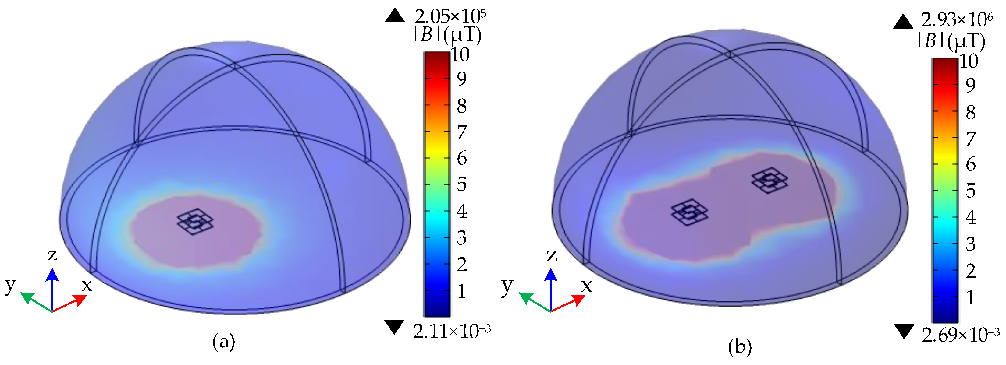
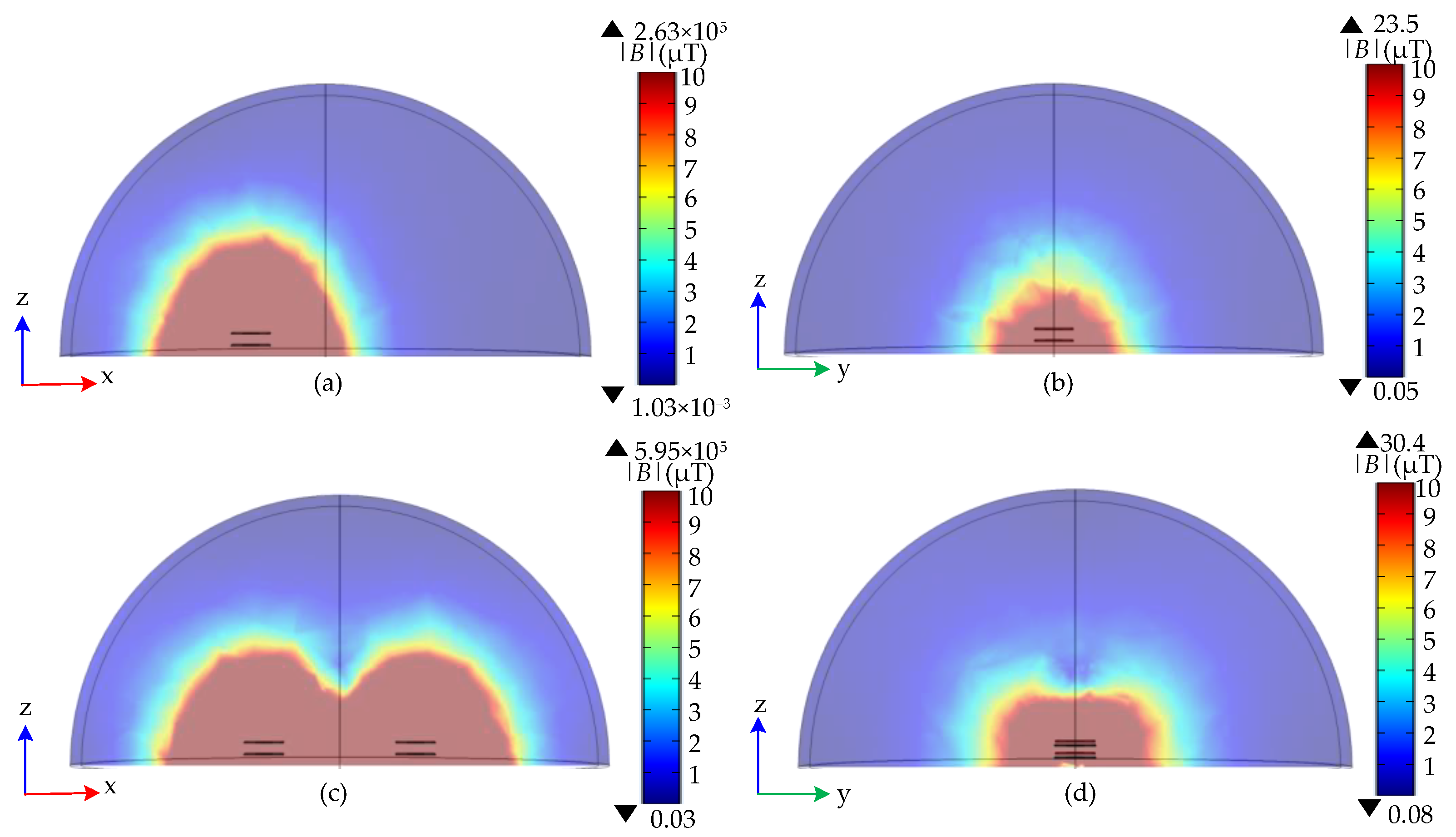
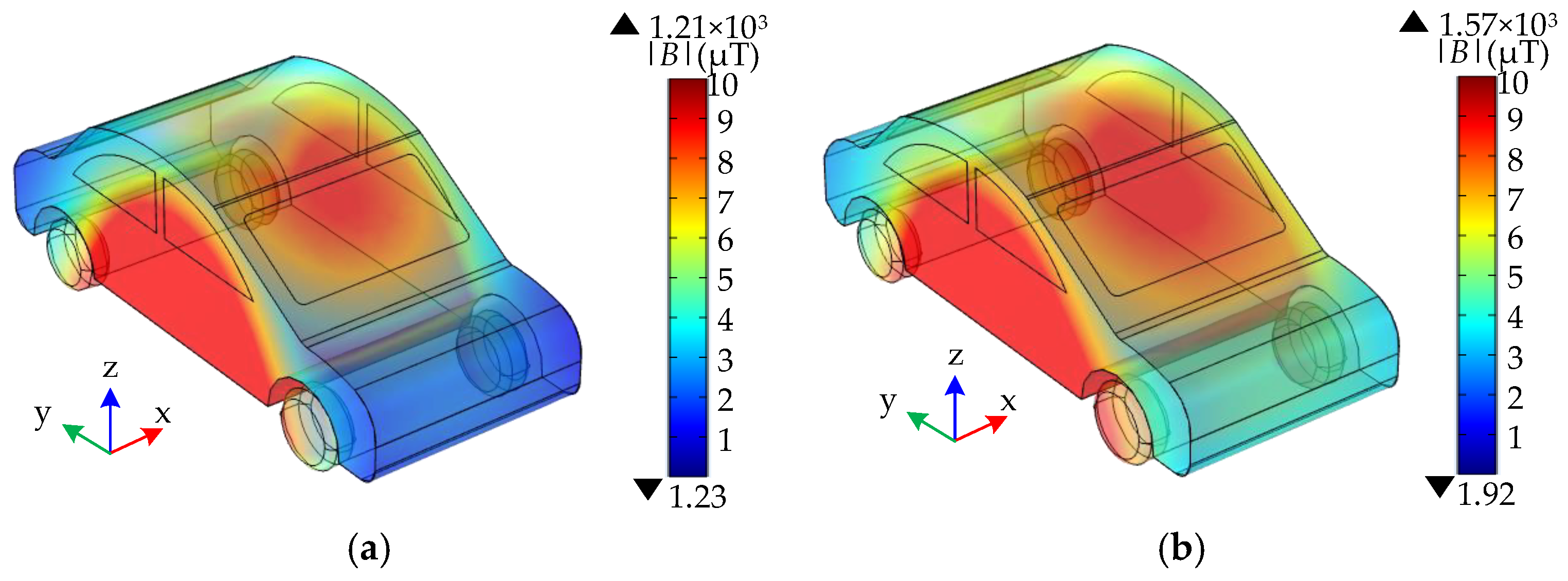
3.1. B Value of Wireless Charger A Working Alone and Two Wireless Chargers Working Simultaneously

Figure 3 shows the distribution of B in simulation space when wireless charger A worked alone and when two wireless chargers worked simultaneously. The maximum value of simulation space B when two wireless chargers worked simultaneously was larger than that when wireless charger A worked alone. When wireless charger A worked alone, and two wireless chargers worked simultaneously, the maximum values of simulation space B were 2.05 × 10⁵ μT and 2.93 × 10⁶ μT, respectively.
The zx and zy sections were taken at the center of the simulation space to observe the changes of B under the two conditions of wireless charger A working alone and two wireless chargers working simultaneously. The distribution of B is shown in Figure 4. Under the two conditions of wireless charger A working alone and two wireless chargers working simultaneously, the maximum values of B in the zx section were 2.63 × 10⁵ μT and 5.95 × 10⁵ μT, respectively, and the maximum values of B in the zy section were 23.5 μT and 30.4 μT, respectively.
Considering the symmetry of the position of the two cars, when wireless charger A worked alone or two wireless chargers worked simultaneously, only the area of car A was selected to observe the change of the B inside the car. When the car body material was set as air, the distribution of B in car A area is shown in Figure 5. When wireless charger A worked alone and two wireless chargers worked simultaneously, the maximum values of B in car A were 1.21 × 10³ μT and 1.57 × 10³ μT, respectively.
The maximum value of B under different conditions is shown in Table 4. When two wireless chargers worked simultaneously, the simulation space was about 143 times that when wireless charger A worked alone, the zx section was 2.24 times that when wireless charger A worked alone, the zy section was 1.29 times that when wireless charger A worked alone, and the interior of car A was 1.30 times that when wireless charger A worked alone. These results indicate that when two wireless chargers work simultaneously, the B value in the simulation space, at the two sections, and in the area of car A all increase in different amplitudes, and more magnetic leakage leads to greater electromagnetic radiation for the driver inside the electric car.

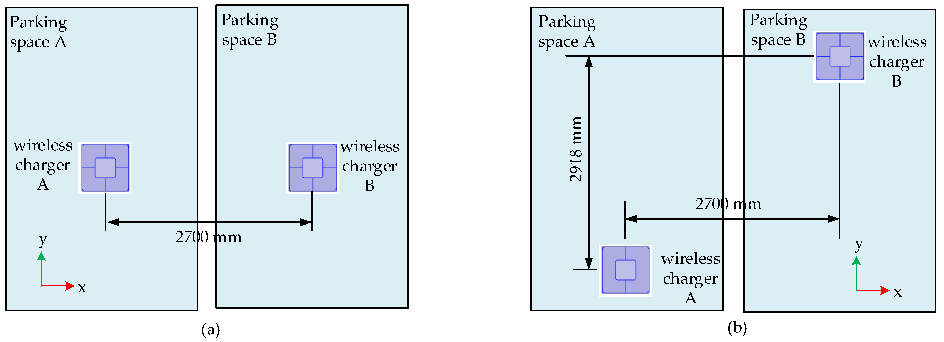
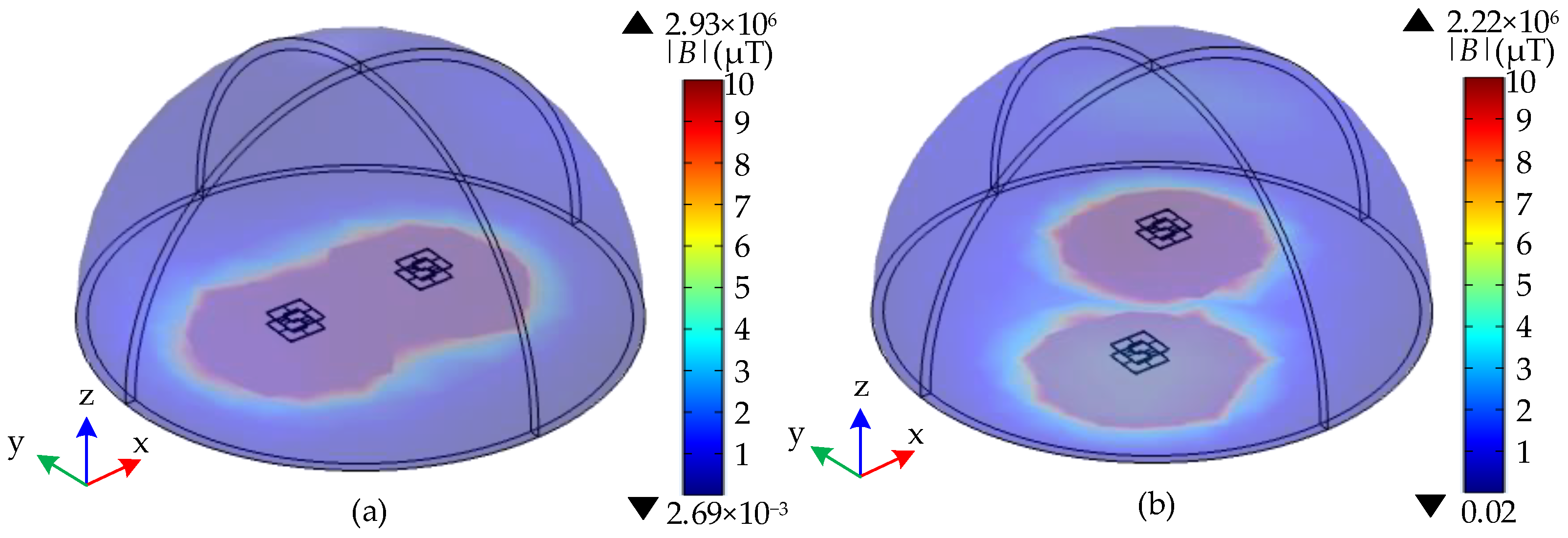
3.2. Simulation Space B under Different Positions of Two Wireless Chargers

To observe the electromagnetic radiation received by the driver inside car A under extreme conditions, the surface B and interior E of the human body were calculated under the condition that wireless charger A and wireless charger B work simultaneously without the protection of car body, as shown in Figure 6. The maximum value of B on the human body surface and internal E were 351 μT and 87.4 V/m, respectively, when two wireless chargers worked simultaneously without car body protection. The red part in the figure exceeded the ICNIRP standard. Figure 6b shows that E in the human head clearly exceeded the standard, which may have a certain effect on the central nervous system of the human body. Therefore, adopting simple, reliable methods to reduce electromagnetic radiation received by the human body to a safe range is a key issue.
To analyze the influence of the relative position of wireless charger A and wireless charger B on simulation space B, considering the space limitation of parking space in the actual situation, the left and right positions of the wireless chargers do not move but only change the parking direction of the car, namely, the front and rear positions, and the purpose is not to affect parking. Therefore, the distance between wireless charger A and wireless charger B remained unchanged in the x direction, and was staggered by 2918 mm in the y direction, as shown in Figure 7. Figure 7a is applicable to the situation that the receiving coil of the wireless charger is at the center of the car chassis. Figure 7b is applicable to the charging scenario where the receiving coil of the wireless charger is at the bottom of the car close to the front of the car and the front of two cars are parked in reverse. The values of simulation space B under the two cases of side-by-side charging of two wireless chargers and staggered charging of two wireless chargers were compared and analyzed. The results are shown in Figure 8. The maximum value of simulation space B was 2.93 × 10⁶ μT when two wireless chargers worked side by side and 2.22 × 10⁶ μT when the two wireless chargers were staggered by 2918 mm. After the two wireless chargers were staggered, the maximum value of simulation space B decreasesd by 24.23%. It indicates that the space magnetic field can be effectively reduced by properly adjusting the position of two wireless chargers in charging pile under the conditions of this paper.

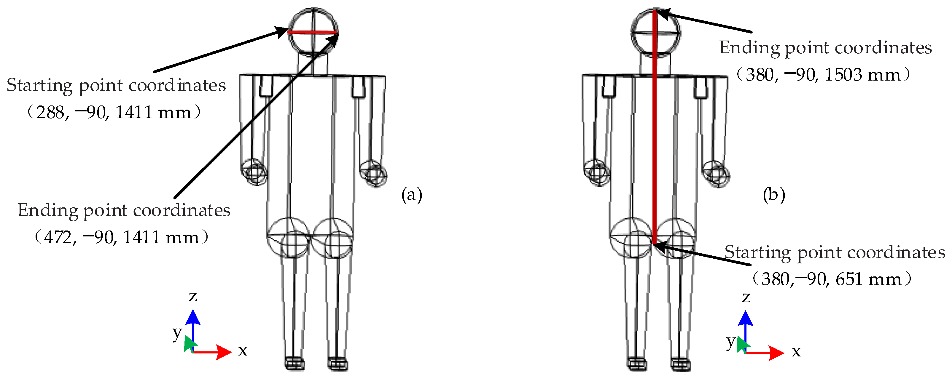
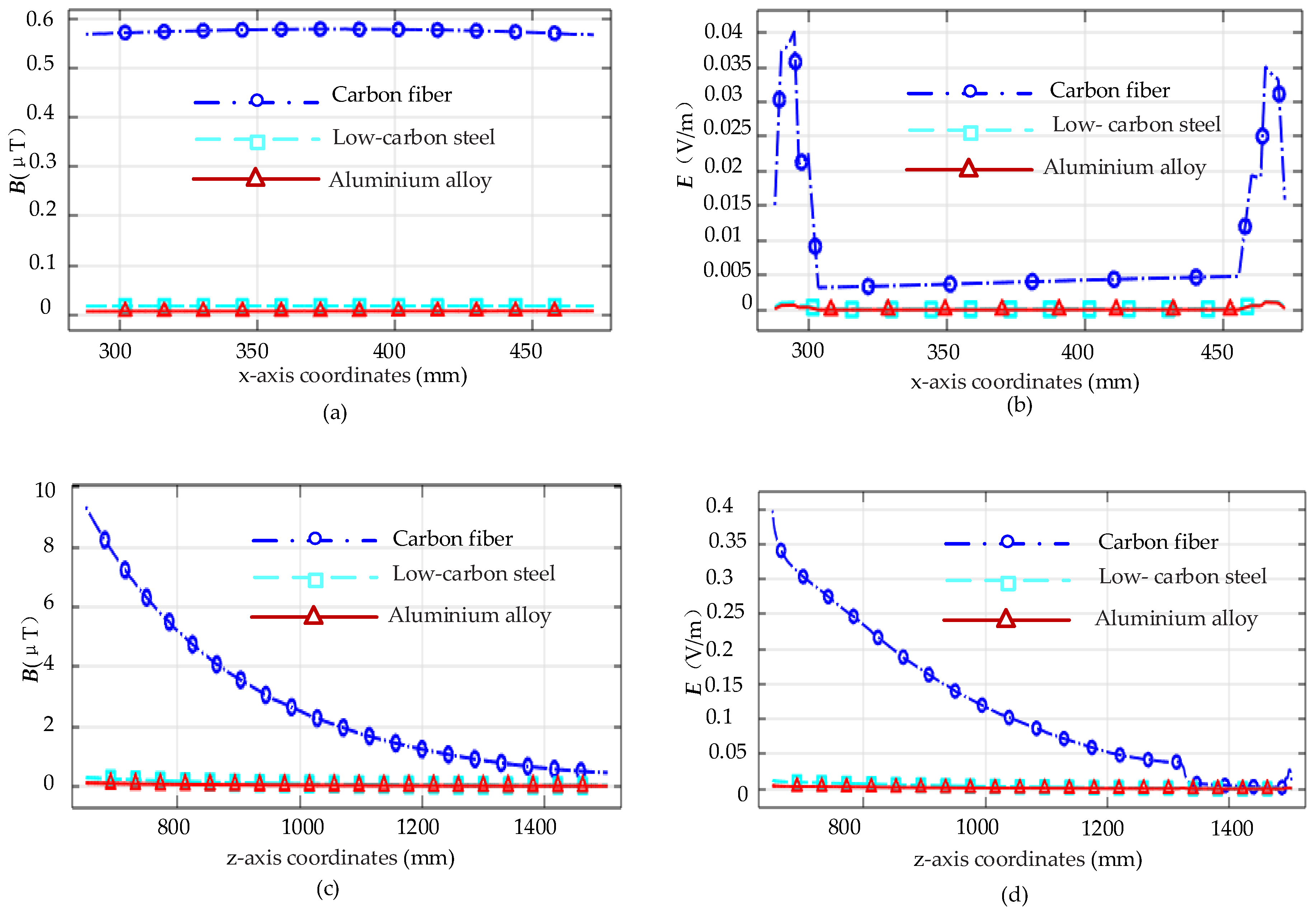
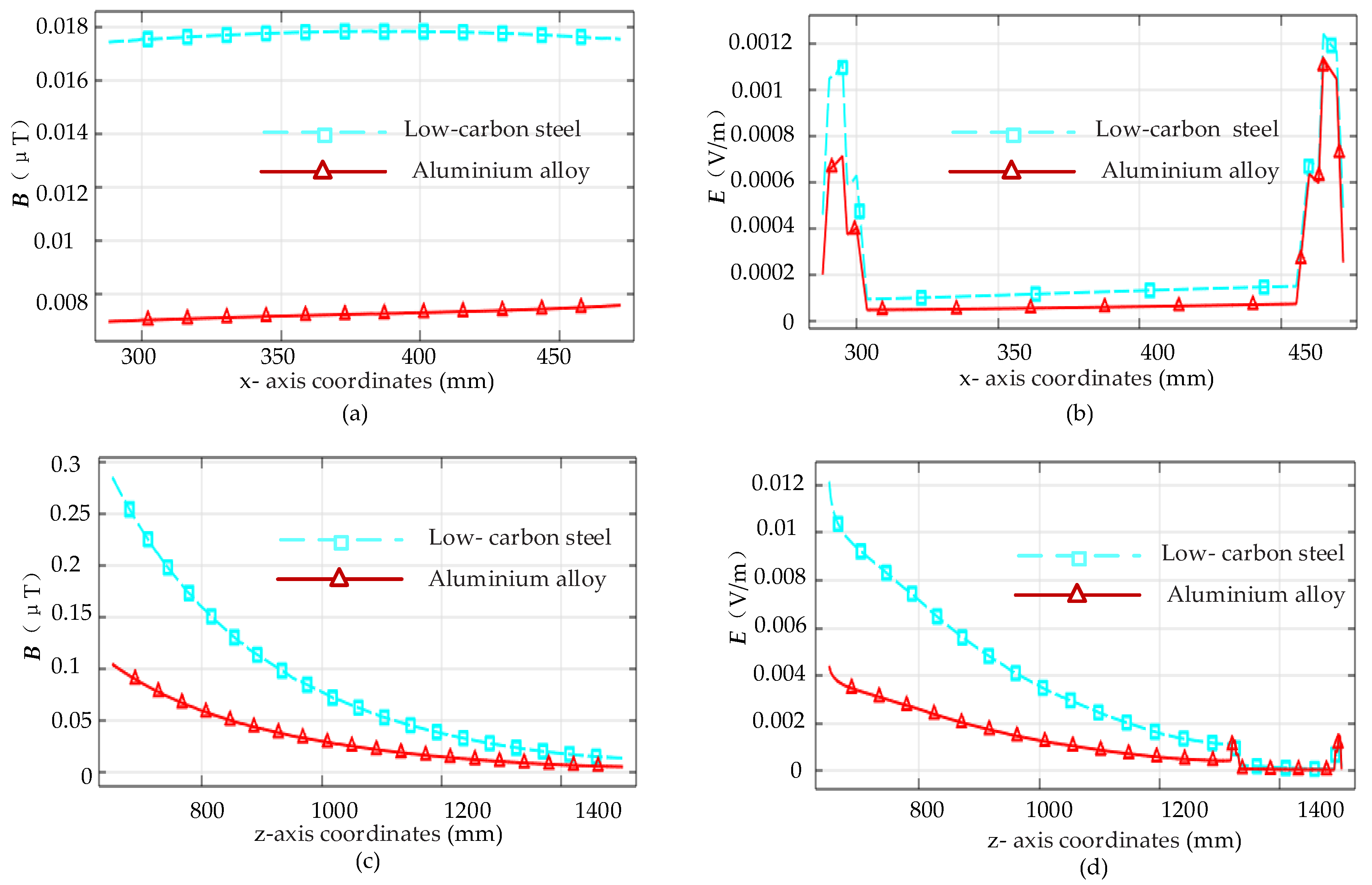
3.3. Influence of Different Car Body Materials

The car body made of metal materials has a certain protective effect on the magnetic leakage generated by the wireless charger [21]. To compare the electromagnetic protection effect of different car body materials on the driver human body, three representative materials, namely, aluminum alloy, low-carbon steel, and carbon fiber, were selected for analysis. Two cutting lines at driver human body in car A were taken, as shown in Figure 9. Figure 9a shows the cross cutting line of the human head, and the coordinates of the starting point and ending point were (288, −90, 1411 mm) and (472, −90, 1411 mm), respectively. Figure 9b shows the longitudinal cutting line from the apex of the human head to the lower part of the abdomen, and the coordinates of starting point and ending point were (380, −90, 651 mm) and (380, −90, 1503 mm), respectively. The values of B and E under the protection of three kinds of car bodies were analyzed at the two cutting lines.
In the case of car bodies made of three different materials, B and E at the cross cutting line of the driver’s head and longitudinal cutting line of the human body in car A are shown in Figure 10. Figure 10a,b show that the protection effect of carbon fiber car body on B and E at the cross cutting line of the human head was worse than that of aluminum alloy and low-carbon steel. The maximum value of B at the cross cutting line of the human head was about 0.6 μT for the carbon fiber car body and about 0 μT for the aluminum alloy and low-carbon steel car body. The maximum value of E at the cross cutting line of the human head was about 0.04 V/m for the carbon fiber car body and about 0 V/m for the aluminum alloy and low-carbon steel car body.
Figure 10c,d show the protection effect of the carbon fiber car body on B and E at the longitudinal cutting line of the human body was worse than that of aluminum alloy and low-carbon steel. The maximum value of B at the longitudinal cutting line of the human body was about 10 μT for carbon fiber car body and about 0 μT for the aluminum alloy and low-carbon steel car body. The maximum value of E at the longitudinal cutting line of the human body was about 0.4 V/m for the carbon fiber car body and about 0 V/m for the aluminum alloy and low-carbon steel car body. With the increase of the distance between the human body longitudinal cutting line and the wireless chargers, B and E had a decreasing trend.
The protective effects of the two materials are shown in further detail because the values of B and E at the human body cutting lines of aluminum alloy car body and low-carbon steel car body were very close. Under the protection of aluminum alloy and low-carbon steel car body, B and E at the cross cutting line of the human head and longitudinal cutting line of the human body are shown in Figure 11. Figure 11a,b show that the protection effect of the low-carbon steel car body on B and E at the cross cutting line of the human head was worse than that of aluminum alloy car body. The maximum value of B and E at the cross cutting line of the human head was about 0.018 μT and 0.0014 V/m in the case of the low-carbon steel car body, respectively, and 0.008 μT and 0.0011 V/m in the case of the aluminum alloy car body, respectively. Figure 11c,d show that the protection effect of low carbon steel car body on B and E at the longitudinal cutting line of the human body was worse than that of the aluminum alloy car body. The maximum value of the human body longitudinal cutting line B and E was about 0.3 μT and 0.012 V/m under the protection of the low-carbon steel body, respectively, and about 0.1 μT and 0.004 V/m under the protection of the aluminum alloy car body, respectively. Under the protection of the aluminum alloy car body, B and E at the cross cutting line of the human head and longitudinal cutting line of the human body were smaller than those of the low-carbon steel car body. Although the aluminum alloy material is more expensive than low-carbon steel, considering that the material is light and the electromagnetic protection effect is better, the aluminum alloy car body material was selected as the protective material in the subsequent research of this paper.

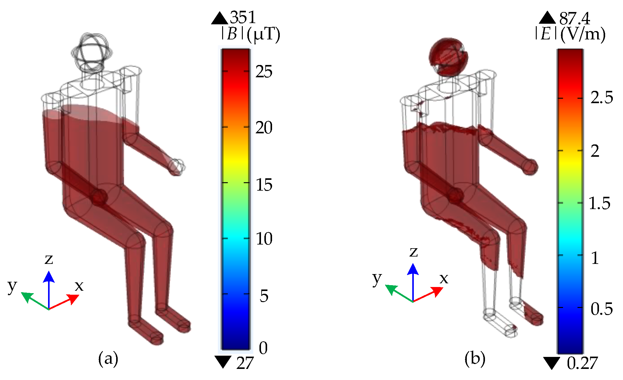
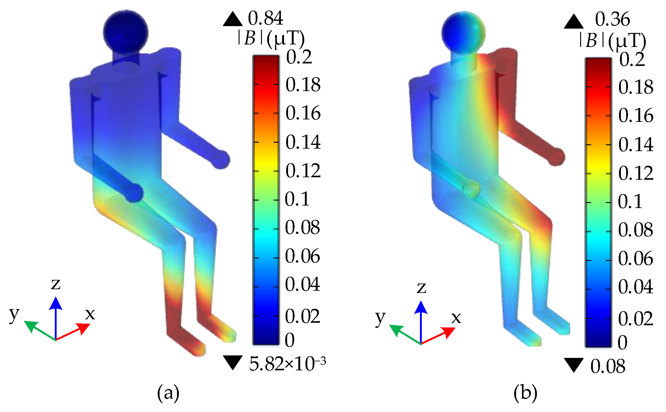
3.4. Electromagnetic Exposure of Driver’s Body under New Measures

After combining the aluminum alloy car body with the staggered front and rear positions of the two wireless chargers, human body surface B in car A was calculated, as shown in Figure 12. After combining the aluminum alloy car body with the staggered method of two wireless chargers, the B on the surface of the human body dropped even lower. After adding the aluminum alloy car body material, when the two wireless chargers worked side by side, the maximum value of human body surface B of the driver in the car was 0.84 μT; when the front and rear positions of the two wireless chargers were staggered, the maximum value of human body surface B of the driver in the car was 0.36 μT; when two wireless chargers worked in staggered front and back directions, the B was 42.9% of that when two chargers worked side by side.
Before and after taking the new measures, the maximum value of driver’s body surface B in car A was compared with the ICNIRP public magnetic field exposure limit, and the percentage value of the simulation value and the limit value was calculated. The results are shown in Table 5.
Table 5 shows that when two wireless chargers worked side by side and no car body existed, the maximum value of B on the human body surface was 351 μT, which is 13 times the ICNIRP limit. Combined with engineering application, after adding the car body material aluminum alloy, when the two wireless chargers worked side by side, the maximum value of B on the human body surface decreased to 3.11% of the ICNIRP limit; when the front and rear directions of the two wireless chargers were staggered, the maximum value of B on the human body surface was reduced to 1.33% of the ICNIRP limit. Under the conditions of this study, the aluminum alloy car body was combined with the staggered method of two chargers, which can better protect the human body from electromagnetic radiation. After taking new protective measures, the maximum value of B on human surface was far less than the ICNIRP exposure limit of 27 μT.

4. Conclusions

In this paper, taking two wireless chargers of electric cars as the electromagnetic exposure source, combined with engineering applications, the magnitude of magnetic leakage generated in the wireless charging of single wireless charger and two wireless chargers was simulated. The protective effects of car body materials on magnetic flux leakage radiation were compared, and the electromagnetic radiation of the driver’s body inside the car after using the aluminum alloy body combined with the staggering method of two wireless chargers was analyzed. The following conclusions were drawn:
(1) When two wireless chargers work simultaneously, the maximum value of B in car A is larger, which is 1.30 times that when wireless charger A works alone;
(2) Staggering the front and rear directions of the two wireless chargers reduces the maximum value of simulation space B by 24.23%, indicating that properly adjusting the relative position of the two wireless chargers can reduce the value of simulation space B;
(3) Aluminum alloy material is superior to low-carbon steel and carbon fiber in electromagnetic protection, and carbon fiber car body has the worst effect. After adding the aluminum alloy car body, when the two wireless chargers work side by side, the maximum value of the surface B of the human body in the driver’s seat in car A can be reduced by 99.76% compared with that before adding materials;
(4) After the aluminum alloy car body material is combined with the staggering method of two wireless chargers, the maximum value of B on the driver’s body surface in car A decreases to 0.102% of that before taking protective measures, which is much less than the public exposure limit of 27 μT, as stipulated in ICNIRP, and it is 1.33% of the ICNIRP limit. The protection method effectively protects the driver in the car from magnetic flux leakage radiation.
The above results can provide a reference for the selection of car body materials of wireless charging EVs and the design of wireless charging stations. It is worth mentioning that the method of staggering the front and rear positions of the two wireless chargers without special shielding measures is effective. For the case that there is already car body material protection, the method of staggering the positions of the two wireless chargers is only icing on the cake, which can better reduce the magnetic leakage in the EV. In order to save computing resources, this paper only studied the electromagnetic exposure scenario of two wireless chargers charging simultaneously; however, in practice, a wireless charging station often has multiple EVs charging simultaneously, and the magnetic leakage generated by charging is larger and more complicated. In the future, it can be extended to the electromagnetic exposure analysis of small wireless charging stations.

Author Contributions

W.M. and M.L. conceived the research and contributed to the research survey and data analysis. All authors have read and agreed to the published version of the manuscript.

Funding

The authors acknowledge the financial support from the National Natural Science Fund of China (51867014).

Institutional Review Board Statement

Not applicable.

Informed Consent Statement

Not applicable.

Data Availability Statement

Not applicable.

Conflicts of Interest

The authors declare no conflict of interest.

References

  1. Citroni, R.; Di Paolo, F.; Livreri, P. A Novel Energy Harvester for Powering Small UAVs: Performance Analysis, Model Validation and Flight Results. Sensors 2019, 19, 1771. [Google Scholar] [CrossRef] [PubMed] [Green Version]
  2. Elsisi, M. Optimal Design of Nonlinear Model Predictive Controller Based on New Modified Multitracker Optimization Algorithm. Int. J. Intell. Syst. 2020, 35, 1857–1878. [Google Scholar] [CrossRef]
  3. Elsisi, M.; Ebrahim, M. Optimal Design of Low Computational Burden Model Predictive Control Based on SSDA towards Autonomous Vehicle under Vision Dynamics. Int. J. Intell. Syst. 2021, 36, 6968–6981. [Google Scholar] [CrossRef]
  4. Zhang, Z.; Pang, H.; Georgiadis, A.; Cecati, C. Wireless Power Transfer—An Overview. IEEE Trans. Ind. Electron. 2019, 66, 1044–1058. [Google Scholar] [CrossRef]
  5. Machura, P.; Santis, V.D.; Li, Q. Driving Range of Electric Vehicles Charged by Wireless Power Transfer. IEEE Trans. Veh. Technol. 2020, 69, 5968–5982. [Google Scholar] [CrossRef]
  6. Arduino, A.; Bottauscio, O.; Chiampi, M.; Giaccone, L.; Liorni, I.; Kuster, N.; Zilberti, L.; Zucca, M. Accuracy Assessment of Numerical Dosimetry for the Evaluation of Human Exposure to Electric Vehicle Inductive Charging Systems. IEEE Trans. Electromagn. Compat. 2020, 62, 1939–1950. [Google Scholar] [CrossRef]
  7. Chung, Y.D.; Park, E.Y.; Lee, W.S.; Lee, J.Y. Impact Investigations and Characteristics by Strong Electromagnetic Field of Wireless Power Charging System for Electric Vehicle Under Air and Water Exposure Indexes. IEEE Trans. Appl. Supercond. 2018, 28, 1–5. [Google Scholar] [CrossRef]
  8. Wang, Q.; Li, W.; Kang, J.; Wang, Y. Electromagnetic Safety Evaluation and Protection Methods for a Wireless Charging System in an Electric Vehicle. IEEE Trans. Electromagn. Compat. 2019, 61, 1914–1925. [Google Scholar] [CrossRef]
  9. Santis, V.D.; Giaccone, L.; Freschi, F. Influence of Posture and Coil Position on the Safety of a WPT System While Recharging a Compact EV. Energies 2021, 14, 7248. [Google Scholar] [CrossRef]
  10. He, Y.Q.; Leung, P.S.W. The Effect of Static Magnetic Field Exposure to Drivers Cognitive Ability. In Proceedings of the 2019 Joint International Symposium on Electromagnetic Compatibility, Sapporo and Asia-Pacific International Symposium on Electromagnetic Compatibility, Sapporo, Japan, 3–7 June 2019. [Google Scholar]
  11. Santis, V.D.; Giaccone, L.; Freschi, F. Chassis Influence on the Exposure Assessment of a Compact EV during WPT Recharging Operations. Magnetochemistry 2021, 7, 25. [Google Scholar] [CrossRef]
  12. Campi, T.; Cruciani, S.; Santis, V.D.; Maradei, F.; Feliziani, M. Magnetic Field Behavior in a Carbon-Fiber Electrical Vehicle Charged by a Wireless Power Transfer System. In Proceedings of the 2017 International Symposium on Electromagnetic Compatibility—EMC EUROPE, Angers, France, 4–7 September 2017. [Google Scholar]
  13. Li, J.; Yin, F.; Wang, L. Transmission Efficiency of Different Shielding Structures in Wireless Power Transfer Systems for Electric Vehicles. CSEE J. Power Energy Syst. 2021, 7, 1247–1255. [Google Scholar]
  14. Lu, C.; Rong, C.; Huang, X.; Hu, Z.; Tao, X.; Wang, S.; Chen, J.; Liu, M. Investigation of Negative and Near-Zero Permeability Metamaterials for Increased Efficiency and Reduced Electromagnetic Field Leakage in a Wireless Power Transfer System. IEEE Trans. Electromagn. Compat. 2019, 61, 1438–1466. [Google Scholar] [CrossRef]
  15. Cruciani, S.; Campi, T.; Maradei, F.; Feliziani, M. Active Shielding Design and Optimization of a Wireless Power Transfer (WPT) System for Automotive. Energies 2020, 13, 5575. [Google Scholar] [CrossRef]
  16. Bima, M.E.; Bhattacharya, I.; Hasan, S.R. Comparative Analysis of Magnetic Materials, Coil Structures and Shielding Materials for Efficient Wireless Power Transfer. In Proceedings of the 2019 IEEE International Symposium on Electromagnetic Compatibility, Signal and Power Integrity, New Orleans, LA, USA, 22–26 July 2019. [Google Scholar]
  17. Hwang, Y.J.; Jang, J.Y. Design and Analysis of a Novel Magnetic Coupler of an In-Wheel Wireless Power Transfer System for Electric Vehicles. Energies 2020, 13, 332. [Google Scholar] [CrossRef] [Green Version]
  18. Vaka, R.; Keshri, R.K. Evaluation and Selection of Shielding Methods for Wireless Charging of E-Rickshaw. Electr. Eng. 2020, 102, 1005–1019. [Google Scholar] [CrossRef]
  19. Tan, L.; Elnail KE, I.; Ju, M.; Huang, X. Comparative Analysis and Design of the Shielding Techniques in WPT Systems for Charging EVs. Energies 2019, 12, 2115. [Google Scholar] [CrossRef] [Green Version]
  20. Watanabe, T.; Hakuta, Y. Evaluation of the Magnetic Field Leakage from Two Wireless Power Transfer Systems for EV/PHV Driven Simultaneously. World Electr. Veh. J. 2019, 10, 41. [Google Scholar] [CrossRef] [Green Version]
  21. Mou, W.; Lu, M. Dosimetry Simulation Research on Electromagnetic Exposure of Wireless Charging Electric Vehicle to Human Central Nervous System. In Proceedings of the 16th IEEE Conference on Industrial Electronics and Applications, ICIEA 2021, Chengdu, China, 1 August 2021. [Google Scholar]
  22. Miwa, K.; Takenaka, T.; Hirata, A. Electromagnetic Dosimetry and Compliance for Wireless Power Transfer Systems in Vehicles. IEEE Trans. Electromagn. Compat. 2019, 61, 2024–2030. [Google Scholar] [CrossRef]
  23. Lu, M.; Ueno, S. Comparison of the Induced Fields Using Different Coil Configurations During Deep Transcranial Magnetic Stimulation. PLoS ONE 2017, 12, e0178422. [Google Scholar] [CrossRef]
  24. Yang, C.; Lu, M. Safety Evaluation for a High Signal Operator with Electric Field Exposure Induced by Contact Wires. Arch. Electr. Eng. 2021, 70, 431–444. [Google Scholar]
  25. ICNIRP. Guidelines for Limiting Exposure to Time-Varying Electric and Magnetic Fields (1 Hz to 100 kHz). Health Phys. 2010, 99, 818–836. [Google Scholar] [CrossRef] [PubMed]
Figure 1. Electromagnetic safety simulation model.
Wevj 13 00095 g001
Figure 2. Finite element discrete model: (a) overall, (b) human body.
Wevj 13 00095 g002
Figure 3. Distribution of simulation space B: (a) charger A works alone, (b) two chargers work simultaneously.
Wevj 13 00095 g003
Figure 4. Distribution of B at the section: (a) charger A works alone (zx section), (b) charger A works alone (zy section), (c) two chargers work simultaneously (zx section), and (d) two chargers work simultaneously (zy section).
Wevj 13 00095 g004
Figure 5. Distribution of B in car A: (a) charger A works alone, (b) two chargers work simultaneously.
Wevj 13 00095 g005
Figure 6. Human body B and E (without car body): (a) surface B, (b) internal E.
Wevj 13 00095 g006
Figure 7. Position of two wireless chargers: (a) side by side, (b) staggered front and rear directions.
Wevj 13 00095 g007
Figure 8. Simulation space B: (a) Two chargers side by side, (b) Staggered front and rear directions of the two chargers.
Wevj 13 00095 g008
Figure 9. Cutting line of human body: (a) head, (b) body.
Wevj 13 00095 g009
Figure 10. B and E at human body cutting lines (three materials): (a) B at the cross cutting line of the head, (b) E at the cross cutting line of the head, (c) B at the longitudinal cutting line of the human body, and (d) E at the longitudinal cutting line of the human body.
Wevj 13 00095 g010
Figure 11. B and E at the human body cutting lines (two materials): (a) B at the cross cutting line of the head, (b) E at the cross cutting line of the head, (c) B at the longitudinal cutting line of the human body, and (d) E at the longitudinal cutting line of the human body.
Wevj 13 00095 g011
Figure 12. B of human body surface: (a) Only the aluminum alloy car body is added, (b) aluminum alloy car body combined with two chargers staggered by 2918 mm.
Wevj 13 00095 g012
Table 1. Parameters of the wireless charger model.
ParametersNumerical Value
Ferrite plate size (length × width × height)/mm × mm × mm700 × 700 × 3
Air gap/mm190
Resonant frequency/kHz22
Transmitting power/kW21.88
Receiving power/kW21.62
Transmission efficiency (%)98.80
Table 2. Dielectric parameters of electric cars.
Car Body and WindowRelative
Permittivity
Conductivity
(S/m)
Relative
Permeability
Aluminum alloy 1.02.33 × 1071
Low carbon steel1.08.41 × 106150
Carbon fiber1.02.50 × 1051
Glass5.51.01
Table 3. Dielectric parameters of human tissues at 22 kHz.
TissuesRelative PermittivityConductivity (S/m)
Cerebral white matter6.73 × 1037.32 × 10−2
Cerebral gray matter1.09 × 1041.21 × 10−1
Cerebrospinal Fluid1.09 × 1022.00 × 100
Blood5.23 × 1037.00 × 10−1
Muscle1.47 × 1043.45 × 10−1
Bone5.47 × 1023.55 × 10−2
Skin1.40 × 1044.63 × 10−3
Table 4. Value of B when charger A works alone or two chargers work simultaneously.
Different PositionsTwo Chargers Work Simultaneously B (μT)Charger A Works Alone B (μT)Two Chargers Work Simultaneously/Charger A Works Alone (Multiple)
Simulation space2.93 × 1062.05 × 105143
The zx section5.95 × 1052.63 × 1052.24
The zy section3.04 × 1012.35 × 1011.29
Inside the car A1.57 × 1031.21 × 1031.30
Table 5. Percentage values of simulation values and ICNIRP limits.
Different MeasuresMagnetic Induction Strength on Human Body Surface |B| (µT)ICNIRP Exposure Limits |B| (µT) [25]Percentage Values
No car body (the two chargers side by side)351271300%
Aluminum alloy car body (the two chargers side by side)0.84273.11%
Aluminum alloy car body (the two chargers are staggered)0.36271.33%
Publisher’s Note: MDPI stays neutral with regard to jurisdictional claims in published maps and institutional affiliations.

