Article

Virtual Constant Signal Injection-Based MTPA Control for IPMSM Considering Partial Derivative Term of Motor Inductance Parameters

1
Weichai Power Co., Ltd., Weifang 261061, China
2
Advanced Electrical Equipment Innovation Center, Zhejiang University, Hangzhou 311107, China
3
School of Electrical Engineering, Tiangong University, Tianjin 300387, China
*
Author to whom correspondence should be addressed.
World Electr. Veh. J. 2022, 13(12), 240; https://doi.org/10.3390/wevj13120240
Submission received: 26 October 2022 / Revised: 7 December 2022 / Accepted: 12 December 2022 / Published: 14 December 2022

Abstract

:
The dq-axis inductance parameter value of the Internal Permanent Magnet Synchronous Motor (IPMSM) will change with the dq-axis current. The Virtual Constant Signal Injection Method (VCSIM)-based Maximum Torque Per Ampere (MTPA) control ignores the partial derivative term of the dq-axis inductance to the dq-axis current when extracting the partial derivative information of the torque to the dq-axis current. This will cause the current to deviate from the MTPA point, which will have a certain impact on the output capacity and efficiency of the motor torque. To solve the above problems, this paper proposes a simple and feasible compensation method by solving the partial derivative information between the dq-axis inductance and the dq-axis current. The experimental results show that the motor efficiency and torque output capability are significantly improved after applying the proposed strategy.

1. Introduction

Interior Permanent Magnet Synchronous Motors (IPMSMs) are widely used in electric vehicle drive systems due to their high-power density and high output torque [1]. In order to make full use of the unique reluctance torque in IPMSM, Maximum Torque Per Ampere (MTPA) control is usually used below the base speed to improve the torque output capability of the motor unit stator current and reduce the copper consumption of the motor unit electromagnetic torque [2].
Existing MTPA control methods can be divided into two types: the offline method and the online method. The offline method usually uses finite element analysis [3,4] or experimental analysis [5,6] to establish a data table of dq-axis current reference values related to torque, or a table of dq-axis inductance related to the dq-axis current, and realize MTPA control by looking up the table. This type of method can reduce the influence of motor parameter changes on the current’s given value when the motor is running, but it requires a number of experiments to be performed in advance, and the data of different motors cannot be used interchangeably. In addition, the dq-axis current reference value is usually calculated by interpolation, which also has certain errors, which affects the accuracy of the dq-axis current given value at the MTPA point.
Online methods can be further divided into formula methods, model methods and signal injection methods. The formula method aims to calculate the torque formula of the motor to obtain the MTPA point. In order to avoid the influence of the motor parameter changes in the formula, the recursive least squares method is used to estimate the q-axis inductance and the permanent magnet flux linkage in [7], and the MTPA control is realized by combining the adaptive control. The model method usually establishes a mathematical model based on constant parameters and then uses the recursive Legendre fuzzy neural network algorithm, variable equivalent parameter MTPA control rate and parameter self-correction method to search for MTPA points [8,9,10,11]. Although the formula method and model method can realize MTPA control, they are more complicated to implement. The signal injection method has received extensive attention in recent years because of its strong robustness to parameter changes. According to different signal types, the signal injection method can be divided into the real signal injection method and virtual signal injection method.
The real signal injection method aims to inject a periodic signal into the actual current, reference flux linkage or voltage vector, adjust the current loop through the torque or rotational speed and use the condition that the partial derivative of the torque to current angle is zero to realize MTPA control [12,13,14]. Although this type of method achieves the accurate acquisition of MTPA points, it will bring additional motor losses due to the signal injection into the control loop. The virtual signal injection method can be divided into the Virtual Sinusoidal Signal Injection Method (VSSIM), Virtual Square Wave Signal Injection Method (VSWSIM) and Virtual Constant Signal Injection Method (VCSIM) according to the injected signal form [15,16,17,18,19,20,21]. VSSIM realizes MTPA control by injecting a periodic sinusoidal signal into the calculated current angle and extracting the partial derivative information of the torque to current angle. Although this method does not actually inject the signal into the control loop to avoid additional losses, this method uses multiple filters to obtain partial derivative information. In order to avoid this problem, VSWSIM is proposed in [20], but the partial derivative information of the torque to current angle extracted by this method will be affected by the high-order partial derivative term, which cannot be eliminated. In order to avoid the use of filters and the fact that the higher-order partial derivatives cannot be eliminated, a VCSIM-based MTPA control strategy is proposed in [21]. The difficulty of the algorithm is simplified and the control precision of MTPA is improved effectively. VCSIM is an ideal MTPA online control strategy at present.
However, we found in our study that VSCIM considers the partial derivatives of the dq-axis inductance to the dq-axis current to be zero when extracting the derivative of the torque and the current angle (dTe/dβ). As the value of dq-axis inductance will change with the change in current amplitude, temperature and other factors, with the increase in current amplitude, the dq-axis inductance value changes more seriously. This indicates that ignoring the partial conductance value of dq-axis inductance to dq-axis current will lead to the deviation of dTe/dβ extracted by VSCIM from the actual value, and the greater the current amplitude, the greater the deviation. Therefore, when the current amplitude is large, the dq-axis current reference value obtained by VSCIM deviates from the MTPA point, and the MTPA control precision becomes worse.
In order to improve the control accuracy of VSCM under large current amplitude, this paper analyzes the control error of VSCM, proposes a simple and feasible compensation method and introduces the realization process of this method. The experimental results show that the proposed method can effectively improve the torque output capacity of VCSIM under large current amplitude, improve the motor efficiency and realize MTPA control more accurately.

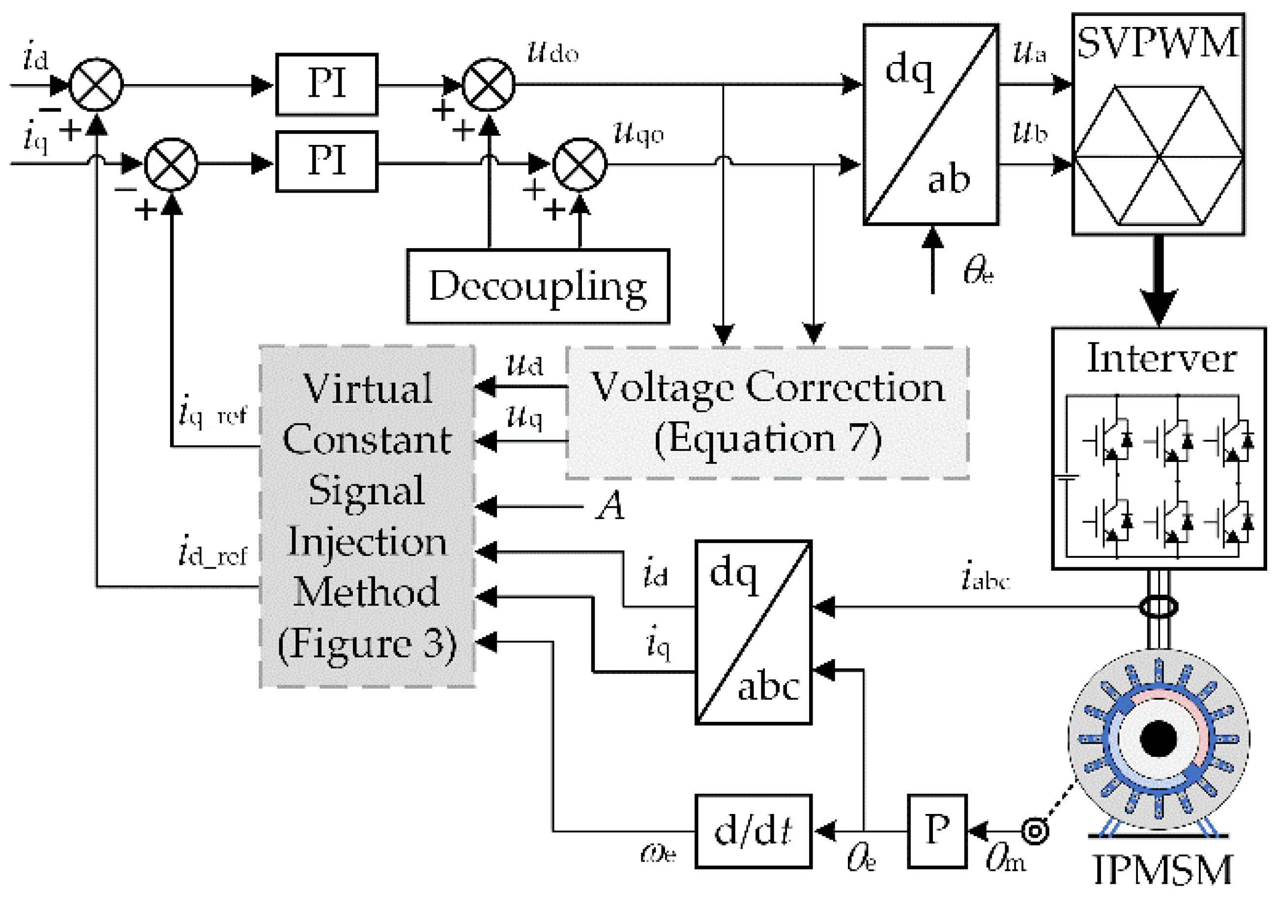
2. MTPA Control Based on Virtual Constant Signal Injection Method

2.1. Mathematical Model of dq-Axis of IPMSM

In the dq-axis coordinate system, the stator voltage equation of the IPMSM can be expressed as
{ u d = R i d + L d d i d d t ω e L q i q u q = R i q + L q d i q d t + ω e ( L d i d + ψ f )
In steady state, the IPMSM stator voltage equation can be expressed as
{ u d = R i d ω e L q i q u q = R i q + ω e ( L d i d + ψ f )
The torque equation of IPMSM can be expressed as
T e = 3 2 p [ ψ f i q + ( L d L q ) i d i q ]
where ud and uq are the dq-axis components of the motor stator voltage, respectively; id and iq are the dq-axis components of the motor stator current, respectively; R is the motor stator resistance; Ld and Lq are the equivalent inductances of the dq-axis of the motor, respectively; ψf is the permanent magnet flux linkage; ωe is the electrical angular velocity of the motor; Te is the torque of the motor; p is the number of pole pairs of the motor.

2.2. The Principle of MTPA Control

The relationship between the dq-axis current of the IPMSM and the current angle β can be expressed as
{ i d = I s sin β i q = I s cos β
where Is is the magnitude of the current vector; β is the angle between the current vector and the q-axis.
Substituting Equation (4) into Equation (3), the relationship between the torque and the current angle can be obtained as
T e = 3 2 p [ ψ f I s cos β 1 2 ( L d L q ) I s 2 sin 2 β ]
It can be determined from Equation (5) that when Is is constant, there is an optimal current angle to maximize the torque, which is called the MTPA angle βMTPA.
β MTPA = arcsin ( ψ f + ψ f 2 + 8 ( L q L d ) 2 I s 2 4 ( L q L d ) I s )
Substituting Equation (6) into Equation (4), the expression of the dq-axis current when the torque is at the maximum can be obtained as
{ i d _ MTPA = I s sin β MTPA i q _ MTPA = I s cos β MTPA
In the current closed-loop control of IPMSM, MTPA control can be realized by setting id_MTPA and iq_MTPA as the dq-axis current reference value, respectively.

2.3. Virtual Constant Signal Injection Method

Due to the influence of ambient temperature and flux saturation, the motor parameters are highly nonlinear, and it is difficult to obtain the parameter values accurately. This will lead to a deviation between the Te calculated by Equation (3) and the actual torque, and then the βMTPA obtained by dTe/dβ = 0 will have a deviation from the actual MTPA angle, so that the torque generated at this angle is not the maximum value. Fortunately, VCSIM has strong robustness to motor parameter changes in the process of realizing MTPA control.
The full differential equation of dTe/dβ can be expressed as
d T e d β = T e i d i d β + T e i q i q β
Substituting Equation (4) into Equation (8), dTe/dβ can be further expressed as
d T e d β = T e i d ( I s cos β ) + T e i q ( I s sin β ) = T e i d i q + T e i q i d
It can be seen from Equation (9) that if we wish to obtain dTe/dβ, we must first accurately obtain ∂Te/∂id and ∂Te/∂iq. Defining the constant value signal A, and injecting A into id and iq in Equation (3), respectively, the torque can be expressed as
{ T e h ( i d + A , i q ) = 3 2 p [ ( L d L q ) ( i d + A ) + ψ f ] i q T e h ( i d , i q + A ) = 3 2 p [ ( L d L q ) i d + ψ f ] ( i q + A )
The binary Taylor series expansion of Equation (10) at (id, iq) can be expressed as
{ T e h ( i d + A , i q ) = T e h ( i d , i q ) + A T e i d + 1 2 A 2 2 T e i d 2 + T e h ( i d , i q + A ) = T e h ( i d , i q ) + A T e i q + 1 2 A 2 2 T e i q 2 +
where
{ T e i d = 3 p ( L d L q ) 2 i q T e i q = 3 p ( ψ f + L d L q ) 2 i d
It can be seen from Equation (12) that the id term is not included in ∂Te/∂id, and the iq term is not included in ∂Te/∂iq, so the second-order and above partial derivatives in Equation (11) are all equal to 0. Equation (11) can be expressed as
{ T e h ( i d + A , i q ) = T e h ( i d , i q ) + A T e i d T e h ( i d , i q + A ) = T e h ( i d , i q ) + A T e i q
Equation (13) can be further expressed as
{ T e i d = [ T e h ( i d + A , i q ) T e h ( i d , i q ) ] / A T e i q = [ T e h ( i d , i q + A ) T e h ( i d , i q ) ] / A
In order to avoid the influence of parameter changes on the partial derivative information, the following transformations are required. When the motor is in steady state, Equation (15) can be obtained from Equation (2).
{ L q = u d R i d ω e i q L d i d + ψ f = u q R i q ω e
Substituting Equation (15) into Equations (3) and (10), respectively, the following equations can be obtained:
T e ( i d , i q ) = 3 2 p ( u d R i d ω e i q i d + u q R i q ω e ) i q
{ T e h ( i d + A , i q ) = 3 2 p [ u d R i d ω e i q ( i d + A ) + u q R i q ω e + A L d ] i q T e h ( i d , i q + A ) = 3 2 p [ u d R i d ω e i q + u q R i q ω e ] ( i q + A )
In Equations (16) and (17), only the stator resistance and d-axis inductance are included. For the IPMSM for electric vehicles, the stator resistance is small, and the influence of the stator resistance change can be ignored [20]. Moreover, the change in d-axis inductance is smaller than that of q-axis inductance in the MTPA stage, and the influence of q-axis inductance is more prominent [15].
The accuracy of ∂Te/∂id and ∂Te/∂iq obtained by Equations (14), (16) and (17) depends on the accuracy of the dq-axis current, dq-axis voltage and rotational speed. Due to the change in rotor position caused by the delay in the control cycle, there will also be a deviation between the voltage output by the current controller and the voltage actually applied to the motor terminal, and the deviation increases with the increase in the rotation speed. Therefore, the output voltage of the current controller needs to be corrected as follows before using it in Equations (15)–(17) [21].
{ u d = k [ u d o cos ( 1.5 ω e T s ) u qo sin ( 1.5 ω e T s ) ] u q = k [ u do sin ( 1.5 ω e T s ) + u qo cos ( 1.5 ω e T s ) ]
where udo and uqo are the dq-axis voltage output by the current controller, respectively; Ts is the control period; k = 2sin(0.5ωeTs)/(ωeTs).
From Equation (9), (14) and (16)–(18), dTe/dβ can be obtained. The dq-axis current reference value at the MTPA point is obtained in the following manner:
(a)
D-axis reference current id_ref
Integrate the extracted dTe/dβ to generate id_ref. When dTe/dβ ≠ 0, id_ref is adjusted under the action of the integrator until dTe/dβ = 0. At this time, id_ref is the d-axis current at the MTPA point.
(b)
Q-axis reference current iq_ref
i q _ ref = { 3 p ψ f T e _ ref / 2 ,   M < 3 2 p ψ f T e _ ref / M ,   M 3 2 p ψ f
where M = Te(id,iq)/iq, and Te_ref is the reference torque.
The schematic diagram of VCSIM is shown in Figure 1.

3. Error Analysis and Error Compensation Method of Virtual Constant Signal Injection Method

3.1. Error Analysis

From Equations (10), (11) and (14), it can be determined that Ld and Lq are regarded as constants independent of id and iq when VCSIM obtains ∂Te/id and ∂Te/∂iq. However, in the actual operation of the IPMSM, the dq-axis inductance varies with the current.
Taking a 60 kW IPMSM as an example, the relationship between the dq-axis inductance and the dq-axis current is as shown in Figure 2.
It can be seen from Figure 2 that with the increase in |id| and iq, both Ld and Lq show a downward trend, and the larger |id| and iq are, the greater the decline in Ld and Lq is. Representing Ld and Lq as implicit functions with id and iq as independent variables, it can be expressed as
{ L dr = L d ( i d , i q ) L qr = L q ( i d , i q )
Substituting Equation (20) into Equation (3), the partial derivative of torque to dq-axis current can be expressed as
{ T er i d = 3 2 p [ ( L dr L qr ) i q + ( L dr i d L qr i d ) i d i q ] T er i q = 3 2 p [ ψ f + ( L dr L qr ) i d + ( L dr i q L qr i q ) i d i q ]
{ 2 T er i d 2 = 3 2 p [ 2 ( L dr i d L qr i d ) i q + ( 2 L dr i d 2 2 L qr i d 2 ) i d i q ] 2 T er i q 2 = 3 2 p [ 2 ( L dr i d L qr i d ) i d + ( 2 L dr i q 2 2 L qr i q 2 ) i d i q ]
{ 3 T er i d 3 = 3 2 p [ 3 ( 2 L dr i d 2 2 L qr i d 2 ) i q + ( 3 L dr i d 3 3 L qr i d 3 ) i d i q ] 3 T er i q 3 = 3 2 p [ 3 ( 2 L dr i d 2 2 L qr i d 2 ) i d + ( 3 L dr i q 3 3 L qr i q 3 ) i d i q ]
From Equations (11) and (14), it can be determined that after considering the change in dq-axis inductance, the errors of ∂Te/∂id and ∂Te/∂iq can be expressed as
{ Δ T e i d = 1 2 A 2 T e i d 2 + 1 6 A 2 3 T e i d 3 + Δ T e i q = 1 2 A 2 T e i q 2 + 1 6 A 2 3 T e i q 3 +
From Equations (9) and (24), the error of dTe/dβ can be expressed as
Δ d T e d β = Δ T e i d i q + Δ T e i q i d
It can be seen from Figure 1 that ΔdTe/dβ and Δ∂Te/∂iq will cause a deviation between the actual reference value of the current and the ideal reference value of the current, which will cause the motor output torque to fail to accurately track the reference torque.

3.2. Error Compensation Method

It can be seen from Equation (11) that when considering the change in inductance, the partial conductance information extracted by VCSIM can be expressed as
{ T e i d = [ T e h ( i d + A , i q ) T e h ( i d , i q ) ] / A Δ T e i d T e i q = [ T e h ( i d , i q + A ) T e h ( i d , i q ) ] / A Δ T e i q
The partial derivative error can be compensated for by obtaining the values of Δ∂Te/∂id and Δ∂Te/∂iq.
In order to facilitate the determination of Δ∂Te/∂id and Δ∂Te/∂iq, the dq-axis inductance is considered to be proportional to the dq-axis current. In other words, the second-order and above partial derivatives of dq-axis inductance to dq-axis current are zero. From Equations (22)–(24), Δ∂Te/∂id and Δ∂Te/∂iq can be expressed as
{ Δ T e i d = 3 2 A M p i q Δ T e i q = 3 2 A N p i d
where M = ∂Ldr/∂id − ∂Lqr/∂id and N = ∂Ldr/∂iq − ∂Lqr/∂iq.
It can be seen from Formula (27) that the key to obtaining Δ∂Te/∂id and Δ∂Te/∂iq lies in obtaining the values of M and N. If the measured motor has a current inductance relation table, ∂Ldr/∂id, ∂Lqr/∂id, ∂Ldr/∂iq and ∂Lqr/∂iq can be obtained by linear fitting. Then, M and N are calculated using the fitting results. In the actual operation of the motor, the inductance current relation table is not completely accurate, so the M and N values should be slightly adjusted according to the experimental results to obtain more accurate compensation effect. If the measured motor does not have a current inductance relation table, it is necessary to select different values of M and N to carry out the experiment. By observing the magnitude of the deviation between the dq-axis current and the MTPA point, the appropriate M and N values are selected.
The control block diagram of VCSIM with inductance partial derivative error compensation is shown in Figure 3.
The block diagram of MTPA control based on the proposed method is shown in Figure 4.

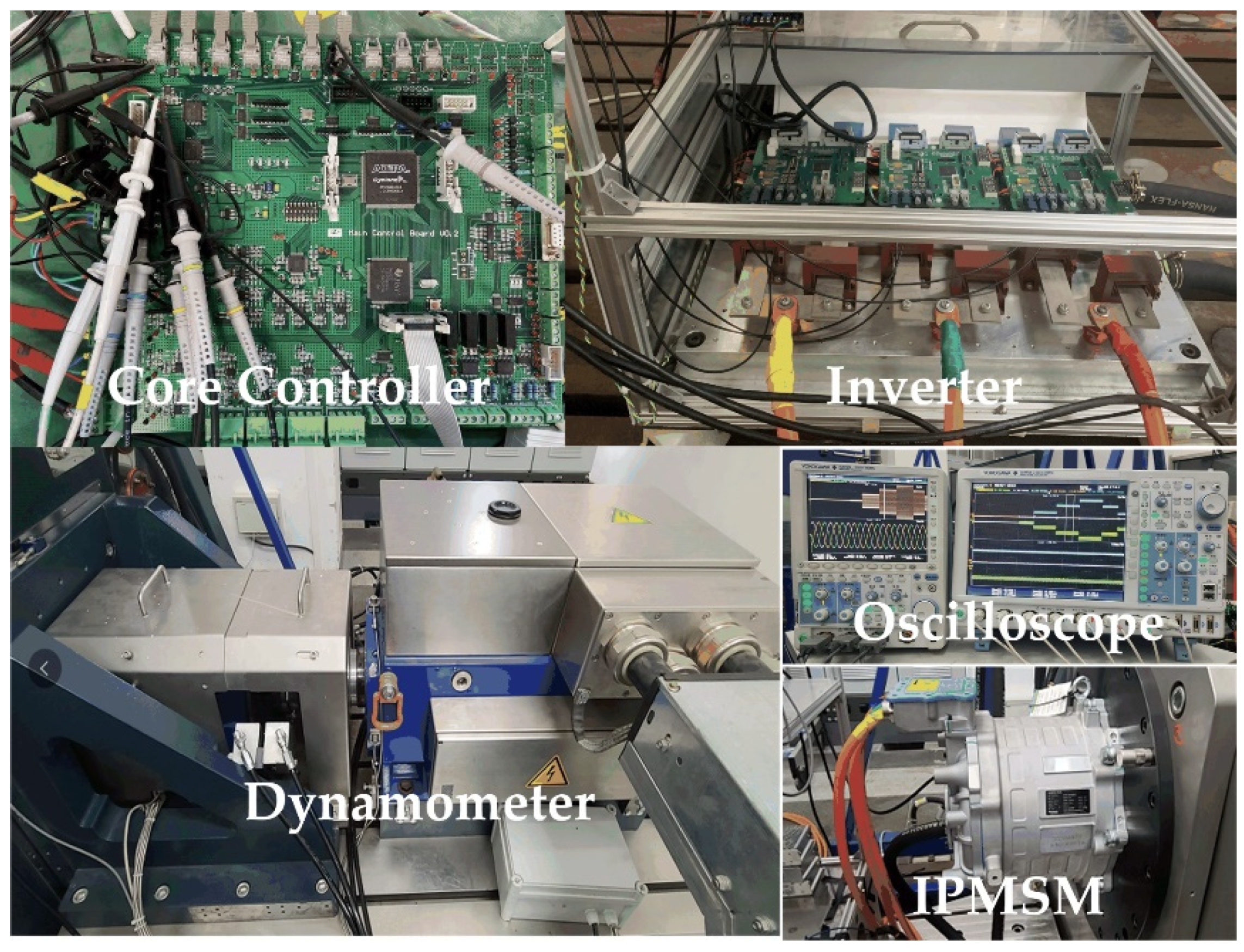
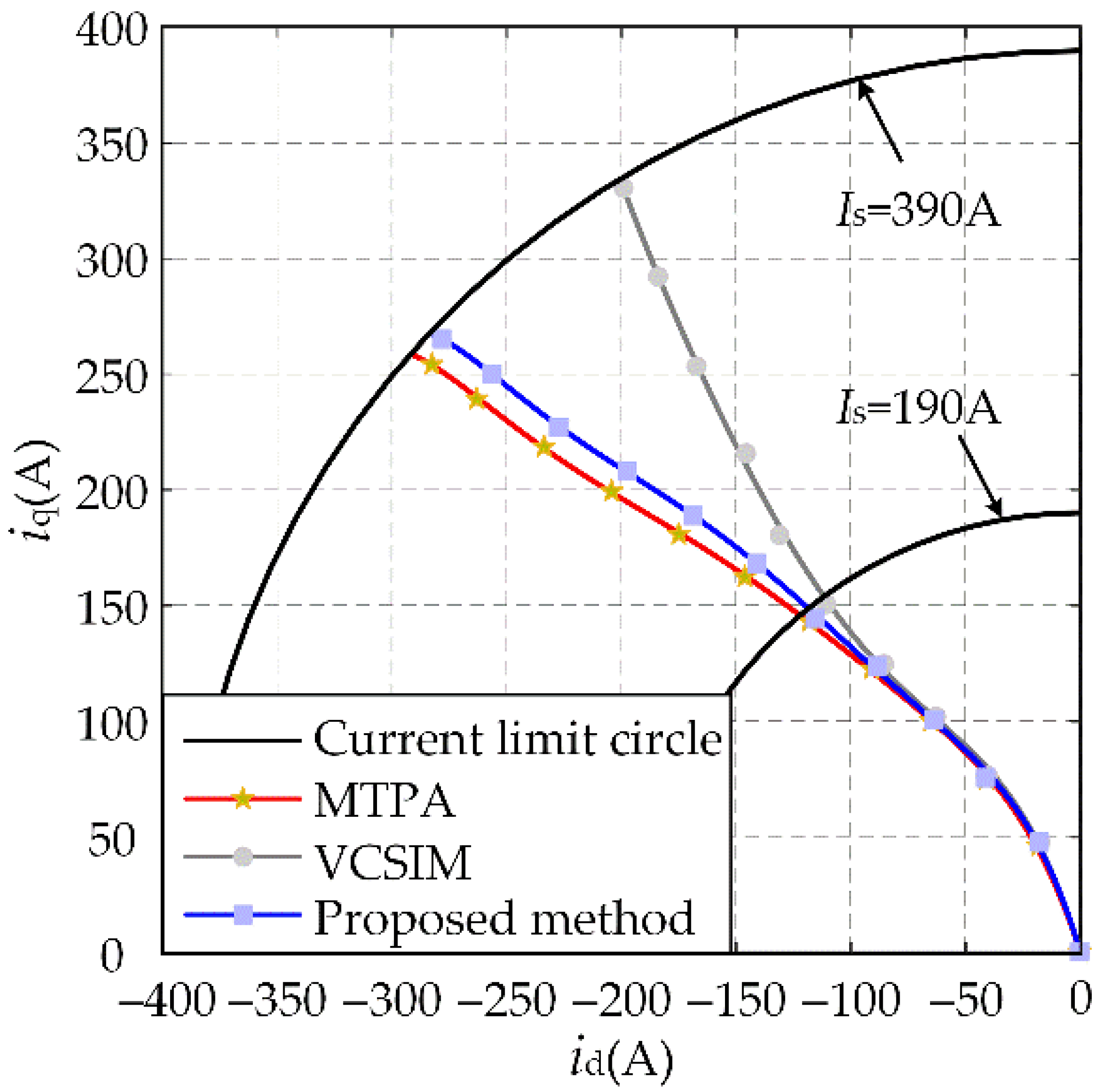
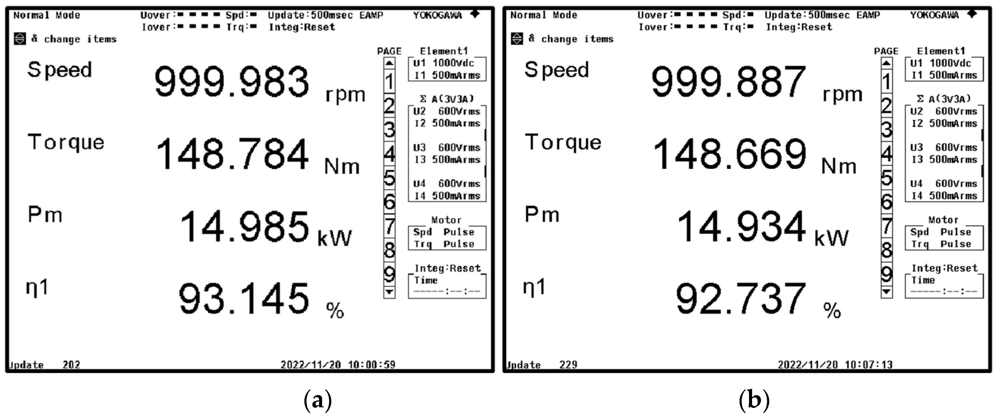
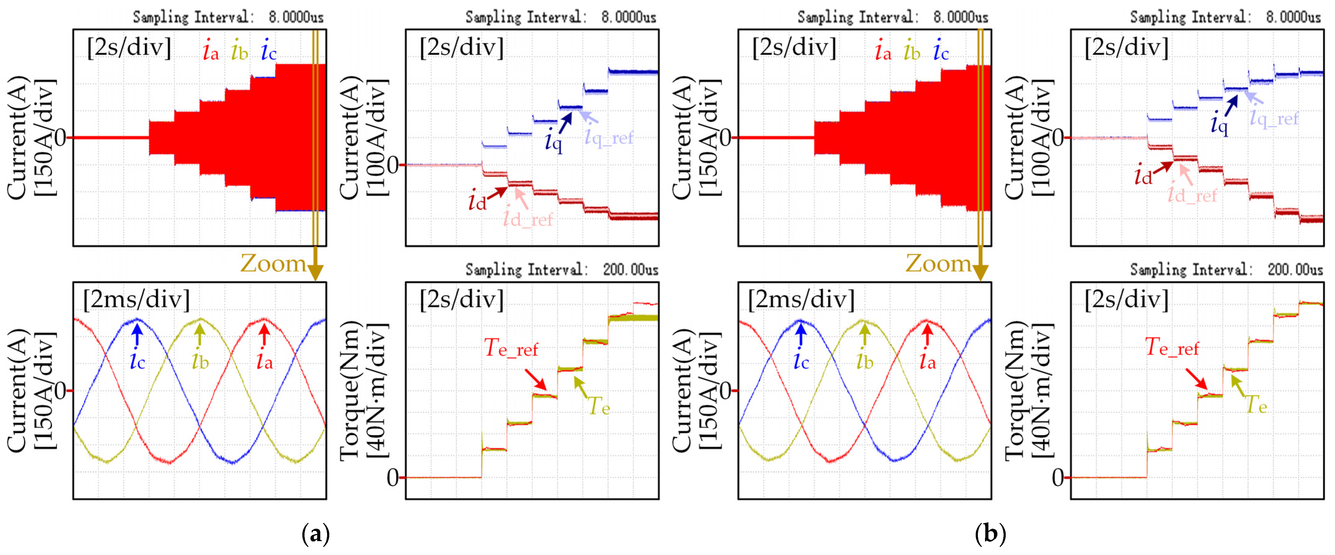
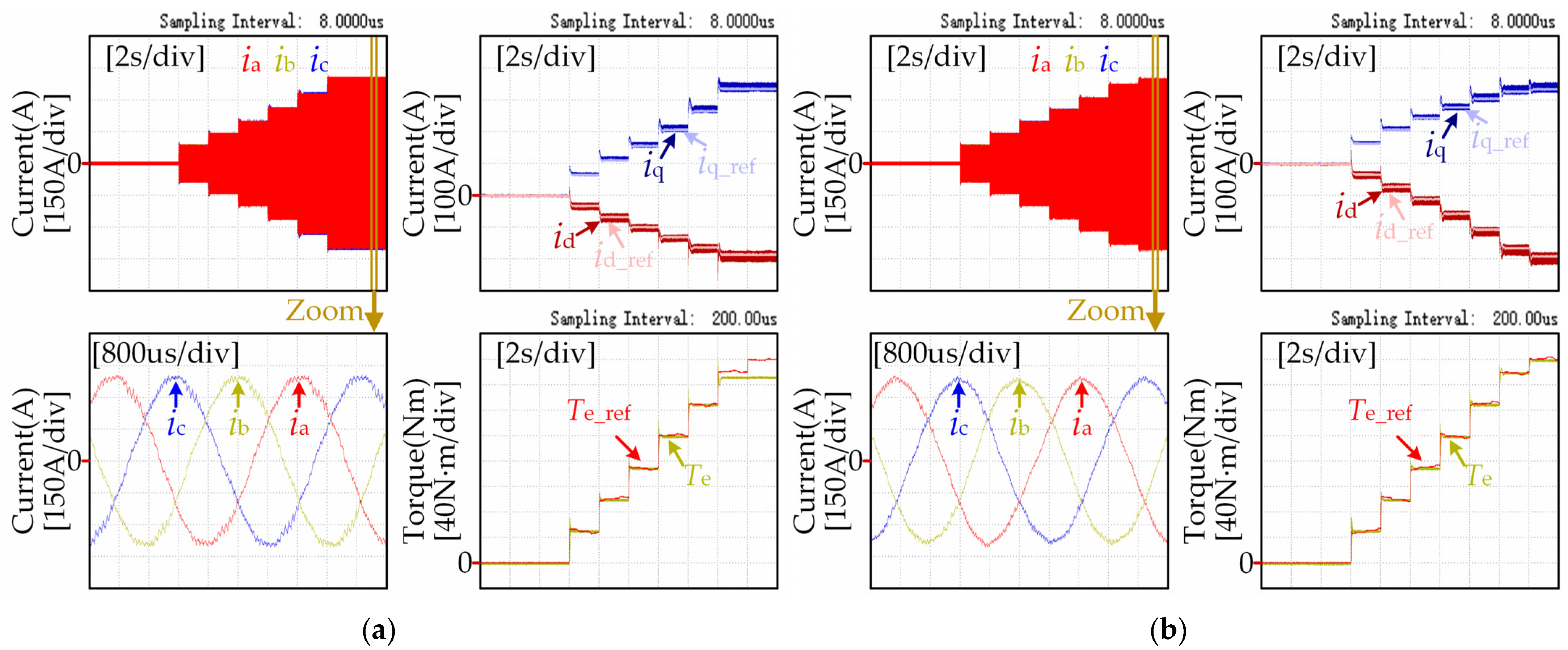
4. Experimental Results and Analysis

To verify the feasibility and the effectiveness of the proposed method, an experimental system, as shown in Figure 5, was set up. The experimental test bench consisted of a dynamometer, an inverter and a control unit, which was built by DSP(TMS320F28335) and FPGA(EP1C6Q240C8). The sampling frequency and carrier frequency of the control system were both 10 kHz. The parameters of the IPMSM are given in Table 1. The values of M and N in the experiment were −1.2 × 10⁻⁶ and 1.1 × 10⁻⁶, respectively.
In order to verify the accuracy of the proposed method for MTPA point tracking, the motor speed was set to 1000 r/min, and the reference torque was increased from 0 N·m to 300 N·m at intervals of 30 N·m, and finally to 320 N·m. The dq-axis current reference values obtained by VCSIM or the proposed method are shown in Figure 6.
The accuracy of MTPA control affects the motor efficiency and torque output capability. In order to verify the advantages of the proposed method, VSCIM and the proposed method were used to observe the motor efficiency and output torque under different reference torque values using a Tokogawa-WT3000 power analyzer at 1000 r/min. The results are illustrated in Figure 7 and Table 2. At the same time, VSCIM and the proposed method were used to observe the three-phase waveform, d-q current waveform and output torque waveform under different reference torque values using a Tokogawa-DLM4058 oscilloscope and Tokogawa-DL850 wave recorder at 1000 r/min and 3000 r/min, respectively. The results are illustrated in Figure 8 and Figure 9.
As can be seen from Figure 7, when the motor runs at 1000 r/min and the output torque is 150 N·m, the motor efficiency when the proposed method is applied is 0.363% higher than the motor efficiency when VSCIM is applied. It can be seen from Table 2 that, compared with VSCIM, when the same torque is output, the current amplitude is smaller and the efficiency is higher when the proposed method is applied. This shows that when the proposed method is applied, the ability to generate torque per unit current is stronger, and the higher the torque is, the more obvious the advantages of the proposed method are.
It can be seen from Figure 8a and Figure 9a that when the motor runs at 1000 r/min and 3000 r/min, respectively, and the given torque is less than 300 N·m, the output torque of the motor can better track the given value when VSCIM is applied. However, when the reference torque is 300 N·m and 320 N·m, the output torque deviates from the reference value, and the maximum output value is 293 N·m. This is because VSCIM ignores the partial derivative of the inductance to the current, which causes the current to deviate from the MTPA point. When the output torque is 293 N·m, the current amplitude reaches the current limit circle boundary value of 390 A. It can be seen from Figure 8b and Figure 9b that the motor output torque can be accurately tracked to the reference torque when the proposed method is applied, which shows that the motor output torque capability of the proposed method is stronger than that of VSCIM. It can be seen from Figure 8 and Figure 9 that under the same output torque, the current amplitude required by VSCIM is larger than that of the method proposed in this paper. Therefore, it is necessary to consider the partial derivative term of the dq-axis inductance to the dq-axis current when solving Equation (9).
The above experimental results show that, compared with VCSIM, the method proposed in this paper has better accuracy for MTPA point tracking, higher motor efficiency and a stronger torque output capability under the same working conditions, and it is more suitable for the field of electric vehicle drives.

5. Conclusions

In order to ensure the accuracy of MTPA control, give full play to the torque output capacity of the motor in the constant torque area and improve the motor efficiency, the existing VCSIM is studied in this paper. Through analysis, it is found that the existing VCSIM ignores the partial conductance of the d-q axis inductor to d-q axis current when obtaining dTe/dβ, which causes the output current to deviate from the MTPA point, thus affecting the motor efficiency and torque output ability. In order to solve this problem, a method to compensate for the partial conductance error by solving the partial conductance value between the d-q axis inductance and the d-q axis current is proposed in this paper. The experimental results show that, compared with the existing VCSIM, the proposed method can realize MTPA control more accurately, and the motor efficiency and torque output capacity are improved significantly, especially under the condition of a large current amplitude.

Author Contributions

Data curation, Z.L.; formal analysis, Z.L.; funding acquisition, X.L; investigation, Q.M. and Q.L.; methodology, Y.X.; project administration, W.C. and X.L.; resources, Z.L.; validation, Z.L. and Y.X.; writing—original draft, Q.M. and Z.L.; writing—review and editing, Q.L. and Y.X. All authors have read and agreed to the published version of the manuscript.

Funding

This research was supported by the Zhejiang Provincial Basic Public Welfare Research Projects, under grant number LGG22E070010, and the Key Program of Tianjin Natural Science Foundation, grant number 20JCZDJC00020.

Data Availability Statement

Not applicable.

Acknowledgments

Sincere thanks to all those who have worked hard on this article.

Conflicts of Interest

Qiang Miao, Qiang Li and Yamei Xu are employees of Weichai Power Co., Ltd., Weifang 261061, China. The paper reflects the views of the scientists and not the company.

References

  1. Shi, T.; Yan, Y.; Zhou, Z.; Xiao, M.; Xia, C. Linear Quadratic Regulator Control for PMSM Drive Systems Using Nonlinear Disturbance Observer. IEEE Trans. Power Electron. 2020, 35, 5093–5101. [Google Scholar] [CrossRef]
  2. Liu, Q.; Hameyer, K. High-Performance Adaptive Torque Control for an IPMSM with Real-Time MTPA Operation. IEEE Trans. Energy Convers. 2017, 32, 571–581. [Google Scholar] [CrossRef]
  3. Jung, S.; Hong, H.; Nam, K. Current Minimizing Torque Control of the IPMSM Using Ferrari’s Method. IEEE Trans. Power Electron. 2013, 28, 5603–5617. [Google Scholar] [CrossRef]
  4. Kim, S.; Sul, S. Speed Control of Interior Permanent Magnet Synchronous Motor Drive for Flux Weakening Operation. IEEE Trans. Ind. Appl. 1997, 33, 43–48. [Google Scholar]
  5. Hoang, K.; Wang, J.; Aorith, H. Online Feedback-Based Field Weakening Control of Interior Permanent Magnet Brushless AC Drives for Traction Applications Accounting for Nonlinear Inverter Characteristics. In Proceedings of the 7th IET International Conference on Power Electronics, Machines and Drives (PEMD 2014), Manchester, UK, 8–10 April 2014. [Google Scholar] [CrossRef]
  6. Morimoto, S.; Sanada, M. Wide-Speed Operation of Interior Permanent Magnet Synchronous Motors with High-Performance Current Regulator. IEEE Trans. Ind. Appl. 1994, 30, 920–926. [Google Scholar] [CrossRef]
  7. Underwood, S.; Husain, I. Online Parameter Estimation and Adaptive Control of Permanent-Magnet Synchronous Machines. IEEE Trans. Ind. Electron. 2009, 57, 2435–2443. [Google Scholar] [CrossRef]
  8. Li, K.; Wang, Y. Maximum Torque Per Ampere (MTPA) Control for IPMSM Drives Based on a Variable-Equivalent-Parameter MTPA Control Law. IEEE Trans. Power Electron. 2019, 34, 7092–7102. [Google Scholar] [CrossRef]
  9. Wang, H.; Li, C.; Geng, Q.; Shi, T. Maximum Torque Per Ampere (MTPA) Control of IPMSM Systems Based on Controller Parameters Self-Modification. IEEE Trans. Veh. Technol. 2020, 69, 2613–2620. [Google Scholar] [CrossRef]
  10. Lin, F.; Huang, M.; Chen, S.; Hsu, C. Intelligent Maximum Torque per Ampere Tracking Control of Synchronous Reluctance Motor Using Recurrent Legendre Fuzzy Neural Network. IEEE Trans. Power Electron. 2019, 34, 12080–12094. [Google Scholar] [CrossRef]
  11. Bolognani, S.; Petrella, R.; Prearo, A.; Sgarbossa, L. Automatic Tracking of MTPA Trajectory in IPM Motor Drives Based on AC Current Injection. IEEE Trans. Ind. Appl. 2011, 47, 105–114. [Google Scholar] [CrossRef]
  12. Liu, G.; Wang, J.; Zhao, W.; Chen, Q. A Novel MTPA Control Strategy for IPMSM Drives by Space Vector Signal Injection. IEEE Trans. Ind. Electron. 2017, 64, 9243–9252. [Google Scholar] [CrossRef]
  13. Xia, J.; Guo, Y.; Li, Z.; Jatskevich, H.; Zhang, X. Step-Signal-Injection-Based Robust MTPA Operation Strategy for Interior Permanent Magnet Synchronous Machines. IEEE Trans. Energy Convers. 2019, 34, 2052–2061. [Google Scholar] [CrossRef]
  14. Li, K.; Wang, Y. Maximum Torque per Ampere (MTPA) Control for IPMSM Drives Using Signal Injection and an MTPA Control Law. IEEE Trans. Ind. Inform. 2019, 15, 5588–5598. [Google Scholar] [CrossRef]
  15. Sun, T.; Wang, J.; Chen, X. Maximum Torque Per Ampere (MTPA) Control for Interior Permanent Magnet Synchronous Machine Drives Based on Virtual Signal Injection. IEEE Trans. Power Electron. 2014, 30, 5036–5045. [Google Scholar] [CrossRef]
  16. Sun, T.; Wang, J. Extension of Virtual-Signal-Injection-Based MTPA Control for Interior Permanent-Magnet Synchronous Machine Drives Into the Field-Weakening Region. IEEE Trans. Ind. Electron. 2015, 62, 6809–6817. [Google Scholar] [CrossRef]
  17. Sun, T.; Wang, J. Self-Learning MTPA Control of Interior Permanent-Magnet Synchronous Machine Drives Based on Virtual Signal Injection. IEEE Trans. Ind. Appl. 2016, 52, 3062–3070. [Google Scholar] [CrossRef]
  18. Sun, T.; Wang, J.; Koc, M. On Accuracy of Virtual Signal Injection based MTPA Operation of Interior Permanent Magnet Synchronous Machine Drives. IEEE Trans. Power Electron. 2017, 33, 7405–7408. [Google Scholar] [CrossRef]
  19. Sun, T.; Koc, M.; Wang, J. MTPA Control of IPMSM Drives Based on Virtual Signal Injection Considering Machine Parameter Variations. IEEE Trans. Ind. Electron. 2018, 65, 6089–6098. [Google Scholar]
  20. Wang, J.; Huang, X.; Yu, D.; Chen, Y.; Zhang, J.; Niu, F.; Feng, Y.; Cao, W.; Zhang, H. An Accurate Virtual Signal Injection Control of MTPA for an IPMSM with Fast Dynamic Response. IEEE Trans. Power Electron. 2018, 33, 7916–7926. [Google Scholar]
  21. Chen, Z.; Yan, Y.; Shi, T.; Gu, X.; Wang, Z.; Xia, C. An Accurate Virtual Signal Injection Control for IPMSM with Improved Torque Output and Widen Speed Region. IEEE Trans. Power Electron. 2021, 36, 1941–1953. [Google Scholar] [CrossRef]
Figure 1. Schematic diagram of VCSIM.
Wevj 13 00240 g001
Figure 2. Relationship between dq-axis inductance and dq-axis current: (a) d-axis inductance, (b) q-axis inductance.
Wevj 13 00240 g002
Figure 3. Block diagram of the proposed method.
Wevj 13 00240 g003
Figure 4. Block diagram of the whole proposed control scheme.
Wevj 13 00240 g004
Figure 5. Diagram of experimental system.
Wevj 13 00240 g005
Figure 6. MTPA tracking experimental result of VCSIM and proposed method when the motor speed is 1000 r/min.
Wevj 13 00240 g006
Figure 7. The comparison diagram of motor efficiency at speed of 1000 r/min and torque of 150 N·m. (a) VCSIM, (b) the proposed method.
Wevj 13 00240 g007
Figure 8. The current and torque waveforms at speed of 1000 r/min and Te_ref = 50, 100, 150, 200, 250, 300, 320 N·m: (a) VCSIM; (b) the proposed method.
Wevj 13 00240 g008
Figure 9. The current and torque waveforms at speed of 3000 r/min and Te_ref = 50, 100, 150, 200, 250, 300, 320 N·m: (a) VCSIM; (b) the proposed method.
Wevj 13 00240 g009
Table 1. The parameters of the IPMSM.
ParametersSymbolValueUnit
Pole pairsp4\
Flux linkageψf0.09398Wb
Stator resistanceRs0.032Ω
d-axis inductanceLd0.437mH
q-axis inductanceLq1.119mH
Rated speednN3820r/min
Rated torqueTN150N·m
Peak torqueTP320N·m
Rated voltageUN540V
Rated currentIN135A
Peak currentIP275A
Table 2. Output torque, current amplitude and efficiency when applying VCSIM and the proposed method.
Te_ref (N·m)VCSIMProposed MethodError
Te1 (N·m)Is1 (A)η1Te2 (N·m)Is2(A)η2Is2Is1 (A)η2η1
3030.2350.2796.77%30.1150.5096.78%0.250.01%
6059.7786.2695.63%59.6785.8195.75%0.480.12%
9089.21119.4094.62%89.23118.6794.78%0.130.16%
120118.94150.9293.76%118.91152.0393.98%−1.460.22%
150148.67186.6692.74%148.78185.5493.15%−2.540.41%
180178.53222.8191.63%178.89219.2792.19%−3.980.57%
210208.15260.2190.32%208.83253.2491.23%−7.110.92%
240237.83303.5688.88%238.67286.5890.29%−14.881.42%
270266.72345.2787.07%268.61321.3789.17%−25.512.09%
300292.35385.7984.97%297.99357.9187.92%−34.862.96%
320\\\316.93384.3786.89%\\
Publisher’s Note: MDPI stays neutral with regard to jurisdictional claims in published maps and institutional affiliations.

