Abstract
Currently, transitioning from fossil fuels to renewable sources of energy is needed, considering the impact of climate change on the globe. From this point of view, there is a need for development in several stages such as storage, transmission, and conversion of power. In this paper, we demonstrate a simulation of a hybrid energy storage system consisting of a battery and fuel cell in parallel operation. The novelty in the proposed system is the inclusion of an electrolyser along with a switching algorithm. The electrolyser consumes electricity to intrinsically produce hydrogen and store it in a tank. This implies that the system consumes electricity as input energy as opposed to hydrogen being the input fuel. The hydrogen produced by the electrolyser and stored in the tank is later utilised by the fuel cell to produce electricity to power the load when needed. Energy is, therefore, stored in the form of hydrogen. A battery of lower capacity is coupled with the fuel cell to handle transient loads. A parallel control algorithm is developed to switch on/off the charging and discharging cycle of the fuel cell and battery depending upon the connected load. Electrically equivalent circuits of a polymer electrolyte membrane electrolyser, polymer electrolyte membrane fuel cell, necessary hydrogen, oxygen, water tanks, and switching controller for the parallel operation were modelled with their respective mathematical equations in MATLAB® Simulink®. In this paper, we mainly focus on the modelling and simulation of the proposed system. The results showcase the simulated system’s mentioned advantages and compare its ability to handle loads to a battery-only system.
1. Introduction
The current global warming scenario is aggravating, at an alarming rate, the increase in the production of greenhouse gases (GHG) [1]. As development progresses, the demand for energy keeps increasing, leaving us with no choice other than to utilise the available reserves and search for additional alternative energy sources [2]. To meet our increasing demands, fossil fuels are being consumed at an exorbitant rate to provide energy for servicing our needs [3]. Combustion of fossil fuels produces GHG which lead to an increase in global temperatures [4]. To fight the issue, the Paris agreement was signed by 194 countries who agreed to slow down the negative impact of climate change by reducing fossil fuel consumption over the course of a decade [5]. Since then, development has shifted focus toward improving the efficiency of producing, storing, and transmitting energy, and since then, invention and innovation of several methodologies have been undertaken to explore ways to improve the system [6]. Despite this, the global warming scenario seems to be escalating steadily, urgently demanding the need for alternative and renewable energy sources [7,8]. Several alternative methods for producing energy have been developed and introduced into the market. From the energy storage point of view, the industry seems to be lagging in terms of the primary technology used to store energy, that is, batteries [9]. Battery technologies have achieved high efficiencies, but they pose a threat to the environment in terms of the materials used to produce them [10].
Several alternatives for storing energy exist in the development stage [11]. Amongst the available options, hydrogen is viewed as one of the most promising alternatives to replace fossil fuels [12]. Governments are establishing ambitious targets for making hydrogen technology commercially viable and are supporting those industries that are focusing on improving this field of technology [4,5]. With the boom of electric cars and their commercial success, hydrogen technology is not far away from taking the helm, as it has the potential to be superior in several factors as compared with existing battery systems [13]. However, the gap is yet to be filled in terms of technological advancements, and making it commercially viable is in the hands of those in research and development [14,15].
The idea of hydrogen being utilised as an energy carrier medium has been around for decades. It started at a scientific meeting in Stockholm in the 1970s, where a group of scientists spoke about sending energy in the form of hydrogen through pipelines [16]. Since then, the trial for exploring hydrogen’s potential has been on and off [17]. Hydrogen has been tested to be used as a means of storing energy. For the past two decades, several companies have developed hydrogen-based systems and have deployed them commercially, especially in the transportation sector [18]. The transportation sector accounts for a significant portion of global energy demand and consumption [19]. Moreover, heavy-duty vehicles that provide transportation services to support industries demand significant energy, which is currently satisfied by relying on diesel as its primary fuel [20].
To date, hydrogen is still considered to be an energy carrier of the future and has begun to establish itself [21]. This is attributed to its high energy density, which enables hydrogen to store enormous amounts of energy that can be later delivered for significantly extended periods [22]. Hydrogen systems have several benefits over existing systems [23]. They are reliable, offer longevity, have a higher energy density, environmental compatibility, flexibility with intermittent renewable sources, low pollution, and a hazard-free nature, and are safer than existing batteries [24,25]. All the highlighted advantages make hydrogen potentially a better choice than batteries in energy-demanding applications. For example, they could be implemented in heavy-duty vehicles to satisfy the energy demand in the transportation sector which accounts for almost a quarter of the total energy demand of the globe [26]. Studies have shown that fuel cell-powered heavy-duty vehicles offer better range, vehicle longevity, and significantly lower transportation and maintenance costs [27]. Hydrogen is a substance with extremely low mass density and very low energy content by volume. This implies that hydrogen occupies a large space to store minimal quantities. Therefore, the storage of hydrogen is a crucial aspect to be considered to utilise fuel cell technology. In practice, three methods are used to store hydrogen: Hydrogen is cooled to extremely low temperatures in cryogenic tanks, compressed and stored in high-pressure tanks, and stored in metal hydride tanks. The first two methods require additional energy to cool/compress hydrogen which add to the operational costs. Metal hydride tanks for storing hydrogen employ metals that absorb hydrogen [28]. The latter is considered to be the best amongst the specified methods due to no requirements for energy, smaller volume, and safety.
Hydrogen is produced by various methods. Electrolysis and steam methane reforming are the two most established methods [29]. Electrolysis is considered to be the better alternative among the two as it is more efficient and reliable [30,31]. It is also the cleanest method [32]. However, an electrolyser requires electricity as a source of energy for producing hydrogen. The source of electricity supplied to the electrolyser determines the nature of the hydrogen. The hydrogen available in the market is classified as green, blue, and grey hydrogen. The term ”green hydrogen” is coined for hydrogen produced from clean and renewable energy sources, whereas ”grey hydrogen” is produced from the electricity generated by the combustion of fossil fuels [33]. ”Blue hydrogen” is produced by a hybrid of renewable and fossil fuel sources and includes carbon capture and storage. The production of blue and grey hydrogen is harmful to the environment. Therefore, the energy source to produce hydrogen is of prime importance [34].
The electrolysis process is a chemical reaction carried out with electrodes, where a water molecule is broken down into hydrogen and oxygen. The electrochemical reaction occurring in an electrolyser is non-spontaneous, and therefore, it requires an external source of electricity. The reaction is further improved by conducting it in a membrane medium that acts as a catalyst. The membrane is non-conductive, and the structure is designed such that the membrane is sandwiched between the electrodes. The process of electrolysis is carried out by an electrolyser. Alternatively, a fuel cell carries out the reverse function of an electrolyser [35]. When hydrogen and oxygen are allowed to contact the membrane of a fuel cell, they undergo a spontaneous reaction producing electricity across its electrodes [36].
Investments into years of research and development have produced several fuel cell technologies. The six main categories are: (a) proton exchange membrane fuel cell (PEMFC), (b) alkaline fuel cell (AFC), (c) phosphoric acid fuel cell (PAFC), (d) molten carbonate fuel cell (MCFC), (e) solid oxide fuel cell (SOFC), and (f) microbial fuel cell (MFC) [12]. The preferable one is the polymer electrolyte membrane (PEM) fuel cell [37]. The electrolysers and fuel cells show great potential for the future as they offer higher efficiency than existing energy systems, with a few commercial downsides that can be filled with the help of research and development. Further advancements in the development of PEM technology have emerged over the years, improving its efficiency by above 75% and reducing its manufacturing costs by a staggering 95% between 2005 and 2012 alone [12]. The reliability of PEM technologies has improved to the stage where they offer excellent support to the intermittent nature of renewable sources, which could ensure the production of green hydrogen in the near future [38]. Recent technologies have emerged that even allow PEM technologies to function bi-directionally as an electrolyser and a fuel cell [39]. The apparatus serves as a regenerative fuel cell and can be used to reform hydrogen.
In the current scenario, fuel cell-based hybrid vehicles are now available in the market. However, fuel cell technology has failed to achieve market success despite its several benefits [40]. The cost of external hydrogen solely accounts for its failure. The major disadvantage of hydrogen is its energy content by volume, which implies that a huge tank is required to store even 1 kg of hydrogen [41]. To overcome this issue, hydrogen should be stored under high pressure or at extremely low temperatures [42]. Alternatively, metal-hydride-based tanks also exist [43]. However, all of this increases the cost and makes storage and transportation of hydrogen difficult and commercially unfeasible. Overall, the major disadvantages in utilising fuel cell technology are: (a) the need for efficient production of green hydrogen, (b) the need for robust ways to store hydrogen, and (c) the need for a low-cost and safe way to transport hydrogen.
In this paper, we illustrate a possible solution to the third issue by eradicating the need for transporting hydrogen fuel to every location. Electric grid lines are available even to remote locations and transmitting energy through the lines is far cheaper than carrying fuel to those locations. A similar reason explains why electric vehicles are promoted over fossil fuel cars even though the electricity needed for the cars is produced by burning fossil fuels. Similarly, instead of transporting hydrogen fuel, electricity could alone be transmitted to the location to produce the necessary hydrogen locally, thereby, lowering costs. This is possible by incorporating an electrolyser that is used to produce hydrogen locally, to be utilized later by a fuel cell to generate and supply electric energy when there is a load. Modelling of a hybrid fuel cell and battery hybrid system has been well explored and its benefits have been illustrated in several journals. However, in this paper, we demonstrate a system where hydrogen is produced intrinsically in the hybrid system with the help of an electrolyser. This carries the advantage of lower charging cost, as transmitting electricity is significantly cheaper than transporting hydrogen. Additionally, the proposed system also has a smart switching algorithm that detects the availability of power supply, load, and state of charges to switch the fuel cell and battery accordingly to charge themselves and supply the load optimally. The proposed hybrid system is still not as efficient to replace batteries in every scenario. Nevertheless, the proposed topology shows potential as it has higher energy density, longer life, and no hazardous materials such as batteries.
As mentioned earlier, an electrolyser is utilised for producing hydrogen intrinsically in the system by consuming electricity, which could be later consumed by a fuel cell based on its demand. This would imply that the system would produce and consume hydrogen of its own within its confined hydrogen, oxygen, and water tanks. Thus, eradicating the need for external production, storage, and transportation of hydrogen, and opening doors for potential hydrogen commerce without the need for hydrogen refuelling stations. The system would reduce operational costs as a trade-off for the initial cost of including an electrolyser. The proposed system is mathematically modelled using MATLAB® Simulink®.
The contribution of this study is to propose a system that excludes the utilisation of hydrogen as fuel input and exploits only the advantages of the hydrogen system. This is accomplished by realising the following aspects:
We focus on designing a mathematical model of the proposed system using MATLAB® Simulink®. The result is the combined system’s mathematical model, which includes an electrolyser, fuel cell, necessary hydrogen, oxygen, and water tanks and the parallel control algorithm modelled in the simulation.
- The main focus is on the topology of the proposed system and not on its current practical viability.
- The design, however, strives to include the practical auxiliary losses of such a system to the extent that mathematical modelling allows it to. This is to ensure a small step toward similarity and closeness to real-world results to try to showcase the solidarity of the proposed system.
- We demonstrate the operation of the proposed system in a test condition with various scenarios to showcase its robust design.
- We also try to demonstrate the advantages of the proposed system as compared with a battery-only system.
The paper is organised in the order as follows: In Section 2, we describe the system working in detail; in Section 3, we describe the modelling of individual components of the system with their respective mathematical equations; in Section 4, we describe the Simulink model of separate components connected to form the proposed system; in Section 5, we discuss the results; and in Section 6, we provide the conclusions.
2. Proposed System
The system proposed in this paper aims to overcome the challenge of input fuel being hydrogen. The system contains an electrolyser and a fuel cell working in either direction of hydrogen reformation. It comprises three tanks, two of them are for storing hydrogen and oxygen produced by the electrolyser and one tank is for storing water produced by the fuel cell. The input power for the system is electricity from the grid. The electrolyser consumes electrical energy and water to produce hydrogen and oxygen, which are stored in their separate tanks. The electrical energy consumed is stored as hydrogen in the form of chemical energy. Therefore, energy is stored for later use. When there is a load connected, the chemical energy of hydrogen is converted into electrical energy with the help of a fuel cell. This cycle eradicates the need for the entire system’s input fuel to be hydrogen, that is, hydrogen is produced internally rather than fed to the system. A fuel cell is not suitable for supplying energy to all types of loads, and has a downside of poor power density. This is overcome by connecting a battery in parallel with the fuel cell. The battery is chosen such that the capacity rating of the battery is much lower than the fuel cell since the battery only serves the purpose of handling load transients. The control algorithm takes care of the switching of the battery.
The switching operation of the system is as follows:
- Charging When a power supply from the grid is available, the electrolyser is switched on to produce hydrogen and the battery is charged simultaneously until they are both full. If a load is connected to the system during the charging process, then, the load is also switched to be directly connected in parallel to the grid. This ensures that the power is not wasted due to auxiliary losses of the cycle, and instead directly powers the load.
- Start When there is no load connected (with no power supply), the fuel cell is switched on. To support the slow start-up time of the fuel cell, the switching control turns on the battery to support the transient.
- Stable supply When the fuel cell is capable of supporting the load stably, the switching control disconnects the battery. When there is a load transient, the switching control connects the battery to handle the transient.
- Recharge battery When the battery state of charge is below a particular threshold, the switching control connects the fuel cell to charge and replenish the battery to a certain SOC value. The switching control checks the fuel availability before connecting the battery. Additionally, the fuel cell is allowed to charge the battery only when it is either able to stably supply a load or when it is not connected to a load at all. This is to ensure that the battery is always available to support the fuel cell during load transients.
The block diagram for the proposed system is shown in Figure 1.
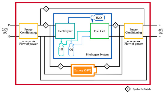
Figure 1.
Block diagram of the proposed system.
Although the simulation system is built to resemble the practical system, the system is designed with certain assumptions and limitations. The assumptions, however, do not significantly affect the system’s output and ensure that the output is comparable. The system assumptions are: (a) The PEM electrolyser and PEM fuel cell systems are assumed to maintain their respective temperatures at a stable value with necessary cooling systems. The assumptions are worth noting as the fuel cell and electrolyser temperature affects the performance figures [44]. (b) The fuel cell and electrolyser stack are assumed to maintain their humidity at stable values. Similar to temperature, the humidity values also appreciably affect the performance values, as they determine the flow of liquids inside the stack. (c) The third assumption points to the internal resistances of the fuel cell stack. In practice, the internal resistance value fluctuates based on various parameters. However, they are not considered in this model and are assumed to have a constant value. (d) The pressure drops inside the fuel cell, and the electrolyser stack is not considered. (e) The modelled tanks in the system are purely mathematical and do not resemble any hydrogen storage system in practice. The auxiliary losses tied with the tanks are not considered. However, the losses are not considered if the tank system is compared to hydrogen storage in metal hydride tanks; they do not require any extra energy [43].
Despite the assumptions, the system has inevitable limitations that are not included in the modelling: (a) The effects of the flow of liquids within the fuel cell and electrolyser stack are not depicted in the modelling of the system. (b) In practice, the performance of the fuel cell depends on its temperature, which implies that the start-up time and response time are affected and varied by the temperature [45]. This system is not dynamically modelled to accommodate this aspect. The modelled system includes constant values of auxiliary losses to accommodate for the limitations up to an extent.
3. System Components
In this section, the modelling and explanation for each component of the system are given in detail along with necessary diagrams and equations. The proposed system is a product of the individual components connected together, considering the unit transformation of parameters between components.
3.1. Buck Converter
Typical energy storage systems operate at a fixed bus voltage value. The bus voltage value of the system is 24 V. Therefore, stepping down and regulating the system’s input and the output voltage is necessary. A buck converter is chosen for simplicity. The input side buck converter feeds power to the electrolyser, while the output side buck converter feeds the load. The selection of buck converter parameters is based on its input and output voltage values. The inductor and capacitor values for the buck converter design were derived from Equations (1) and (2) [46]. The circuit is designed in a closed-loop structure to get a stable and reliable output. The equivalent circuit diagram of the buck converter is depicted in Figure 2.
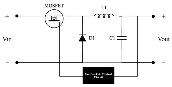
Figure 2.
Buck converter circuit diagram.
3.2. Fuel Cell
Fuel cells can be modelled in three different forms: equivalent electrical, chemical, and experimental models [44]. An experimental model requires actual fuel cell hardware, which incurs high capital costs. This can be avoided by utilising the other two models. A chemical equivalent model requires knowledge of several thermodynamic aspects such as diffusion, mass transport, and heat transfer, which make the system complex and difficult to debug [44]. An electrical equivalent circuit is established using mathematical equations that facilitate the simulation to perform the significant weight lifting.
The elemental electromotive force produced by the cell is given by the Nernst equation of a fuel cell described in Equation (3). The significant losses governing the output of the fuel are concentration losses, activation losses, and ohmic losses. The concentration losses are caused due to limitations in the mass transport of electrons inside the stack during high current densities. The concentration losses are considered by the voltage constant. The operation of the fuel cell has little effect on the concentration losses. Therefore, the open-circuit voltage is described in Equation (4). The activation losses are included during operation, where it is caused by the uncertainties resulting in slower reaction rates inside the fuel cell, affecting the fuel cell’s performance by not meeting the load demand. This is described in Equation (5). In practice, the fuel cell’s output voltage is further affected due to the inclusion of its ohmic losses. The net output voltage of the fuel cell is given by Equation (6). The Tafel slope used in the activation determines the ability of the fuel cell to adapt its current concerning the change in its voltage, given in Equation (7):
3.3. Electrolyser
For the modelling of the electrolyser, the equations describing its operation are derived from thermodynamic aspects. However, the formulas governing the operation of an electrolyser are rather simpler. They are obtained from Faraday’s laws of electrolysis. An equivalent circuit of a required electrolyser is modelled using the mathematical equations in MATLAB® Simulink®. The equivalent circuit of the electrolyser is shown in Figure 3. The expected output from the electrolyser is the hydrogen production rate, given in Equation (8) [13]. The amount of hydrogen produced by the electrolyser depends on the current drawn by the electrolyser and the molar volume of hydrogen. The formula for molar volume is given in Equation (9):
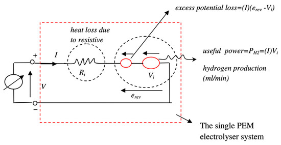
Figure 3.
Equivalent circuit of the PEM electrolyser.
3.4. Storage Tanks: H2/O2/H2O
There are three tanks in the proposed system: hydrogen, oxygen, and water. The tanks play a crucial part in the proposed system as they store the necessary fluids. On the one hand, the electrolyser consumes electricity and water to produce hydrogen and oxygen, which are stored in the first two tanks. On the other hand, the fuel cell consumes from these tanks to produce electricity and water. The water produced by the fuel cell is stored in the water tank, which is again consumed by the electrolyser. The cycle goes on and on depending on the charging and discharging cycle of the system. A dynamic module for the tank level is constructed in MATLAB® Simulink® based on the instantaneous pressure of the tank given by Equation (10), and the formula for the compressibility factor is given in Equation (11) (the tanks modelled in the system are purely mathematical and do not replicate any of the specified tank systems):
The consumption and production of each fluid in its respective tanks are governed by Equations (12)–(14) [7]:
On the fuel cell’s side, the H2 and O2 consumption and H2O production are given by Equations (15)–(17):
Similarly, on the electrolysers’ side, H2 and O2 production and H2O consumption are given by the Equations (18)–(20) [7]:
3.5. Control Algorithm
The control algorithm governs the system’s operation. The system’s algorithm is pictorially depicted as a flowchart in Figure 4. In total, 13 unique cases are derived as a permutation of unique cases from Figure 4. Based on the availability of power supply and load, the switching ensures optimal charging and discharging for all cases of operation. To do this, the system has four switches: at the input side of the electrolyser (EL), at the output side of the fuel cell (FC), at the input side of the battery charging circuit (BI), and at the supply to load connection circuit (IL). These four switches are turned on/off based on a unique combination sent by the ”control algorithm” block. To produce this unique set of Boolean codes, the system reads four different parameters in Boolean format to identify the current case of operation. The four input parameters are the detection of power supply availability (IN), detection of load (OUT), H2 fuel availability (FS) and battery SOC (BS). The unique output code for each case along with input and output Boolean parameters are illustrated in Table 1. The novelty in the algorithm is that it controls the charging of the system, simultaneously supplies the load when there is a power supply, and smartly recharges the battery with the fuel cell if it can, even in the presence of a load.
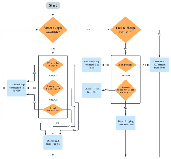
Figure 4.
Flowchart of the switching algorithm.

Table 1.
Switching algorithm with legend.
4. Simulation
4.1. System Simulink Models
The entire proposed system is modelled using Simulink as separate blocks that are connected to resemble the entire system. The whole system is shown in Figure 5. Each block containing segments of the system is further illustrated in detail.
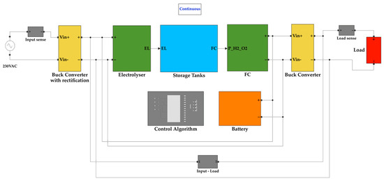
Figure 5.
Simulink model of the proposed system.
The buck converter on the input side takes its input from the isolation and rectification circuit. The isolation secures the system from surges while the rectification circuit converts the AC input waveform into a DC waveform. The buck converter then steps down the voltage to 24 V, which is the operating voltage of the electrolyser. Figure 6 depicts the buck converter on the input side.
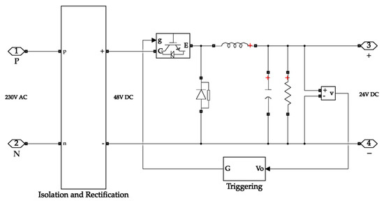
Figure 6.
Buck converter with rectification on the input side of the system.
The electrolyser block calculates the ideal potential of one cell, the molar volume of hydrogen, and the amount of hydrogen produced by the electrolyser. The electrolyser output carries the value of the amount of hydrogen produced, the number of cells in the stack, electrolyser current, and molar volume. The Simulink diagram for the electrolyser system is depicted in Figure 7. The hydrogen tank requires the molar volume value for calculating the tank pressure. At the same time, the remaining values are necessary for calculating the hydrogen consumed and tank quantity values.
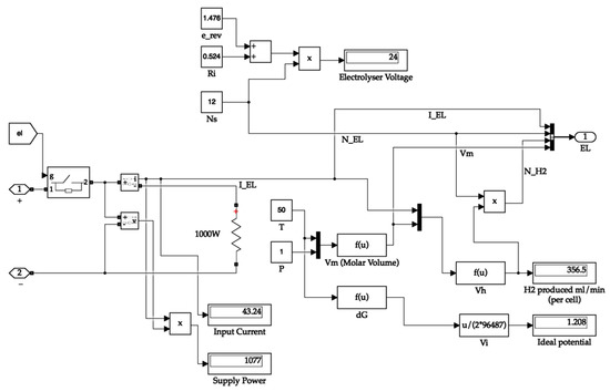
Figure 7.
Electrolyser system.
The hydrogen tank system calculates the hydrogen consumed and the partial pressure of the tank. The hydrogen produced is directly available from the electrolyser. The tank receives the fuel cell current value to calculate the hydrogen consumed value. The tank passes its partial pressure value to the fuel cell for its operation. It uses the hydrogen produced and consumed values to calculate the quantity of hydrogen in the tank. Additionally, the latter values are sent to the oxygen and water tanks, where their quantities are proportionally calculated. The storage tank system is shown in Figure 8. The hydrogen tank system is depicted in Figure 9.
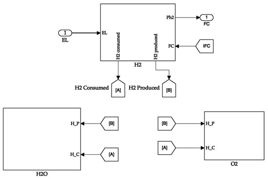
Figure 8.
Storage tank system.
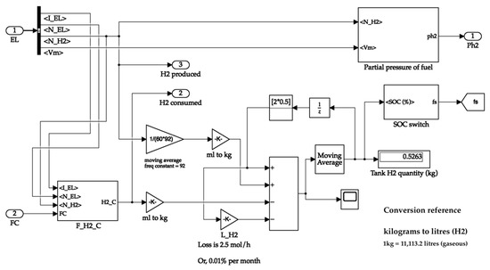
Figure 9.
Hydrogen storage tank.
The fuel cell system receives the partial pressure value from the tank system and passes it to the block containing its stack. The other necessary parameters of the fuel cell that are assumed to be static are fed into the stack block in the form of constants. The fuel cell block calculates the output voltage value of the fuel cell and generates an electrical equivalent signal. The signal terminals are considered to be the output of the fuel cell. Figure 10 shows the inside of the fuel cell block. Figure 11 illustrates the simulation circuit of the output side buck converter.
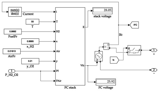
Figure 10.
Fuel cell system.
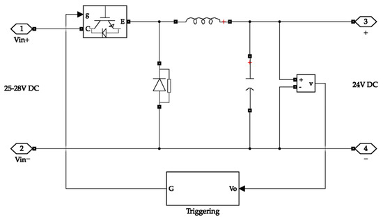
Figure 11.
Buck converter on the output side.
4.2. Simulation of Comparison Test
To compare and illustrate the difference in energy consumption between the hybrid and battery-only systems, a test condition of an electric kart (low power) is designed for simulation. The vehicle drive cycle is simulated on a global homologation drive cycle namely, the “worldwide harmonized light vehicle test procedure” (WLTC) for estimating the energy consumption in Wh/km. Since the modelled vehicle is of low power, class 1 WLTC is adopted for the simulation (for vehicles with a low power-to-weight ratio). The simulation for the test condition is designed in Scilab®. Figure 12 shows the adopted WLTC drive cycle and Figure 13 shows the simulation design for the test.
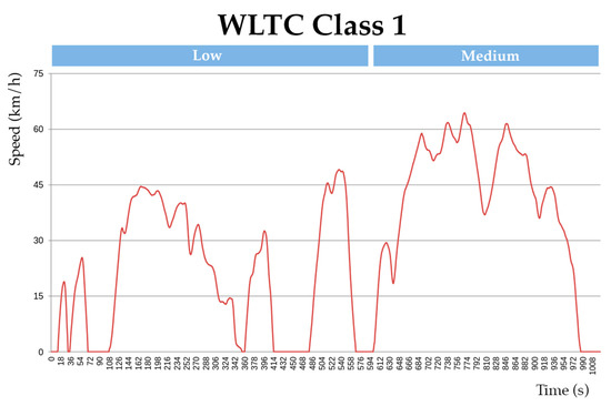
Figure 12.
Class 1 WLTC drive cycle.

Figure 13.
Scilab® simulation diagram.
The specifications of the vehicle and both of the energy systems are illustrated in Table 2 below. To facilitate the necessary simulation, the values of the specifications were adopted from Ballard Power Systems® Nexa 1.2 kW Fuel Cell, Exicom® 2 kWh Li-ion battery, Bosch® 750Wh battery, and Quantum Fuel Systems® 1 kg hydrogen tank [47,48,49,50,51]. The values are considered purely for virtual comparison purposes and not to compare with a real-world scenario. Table 2 displays the specifications in a compiled fashion.
Table 2.
Vehicle and energy system specifications.
5. Results and Discussions
Before discussing the obtained results, it is vital to clarify the application of the proposed system. The proposed system is an alternative for applications where a battery is used. The hybrid system intends to replace the battery in large-scale scenarios where a fuel cell, electrolyser, and battery can be accommodated, for example, in an electric vehicle. To illustrate the working of the developed hybrid system, a test situation is considered with different sections. All the sections collectively illustrate the hybrid system’s output in different scenarios. For understanding, section (n) will be considered the period between section (n) and section (n + 1) in the graphs shown in Figure 14 and Figure 15. In Section 1, the hybrid system is given a power supply from the grid. In this section, it is depicted that the switching algorithm turns on the electrolyser and also allows the battery to charge. In Section 2, a load of 800 W is connected while the input supply is still available. In this section, since the power supply is still available, the electrolyser is still switched on to produce hydrogen. Additionally, the system supplies power to the load directly by conditioning the voltage from the grid. This is depicted in the input and load graphs, where the input power increases with load. The fuel cell and battery output graphs show that no power is withdrawn from them in this section. In Section 3, the load is disconnected while the supply is on, switching the system back to the way it functioned in Section 1. The input power supply is then disconnected in Section 4.
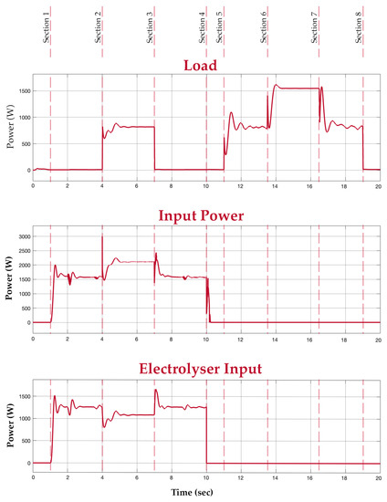
Figure 14.
Load, input, and electrolyser graphs.
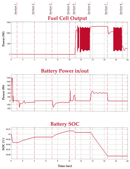
Figure 15.
Fuel cell, battery, and battery SOC graphs.
In Section 5, a load of 800 W is introduced again, now in the absence of an input power supply. In this period, the fuel cell is turned on to supply power to the load. This is depicted in the load and fuel cell graphs. At this medium load, the mean power value of the fuel cell is considered. The buck converter, however, smoothens the output. In Section 6, an extra load of 800 W is connected to the system. Since the new total load exceeds the fuel cell’s power rating of 1.26 kW, the battery supports the fuel cell to meet the new load demand. This is depicted in the battery graph. Section 7 has the extra load disconnected, switching the system back to the way it functioned during Section 5. Finally, in Section 8, all loads are disconnected and there is also no input power. It is evident from the graphs that the battery supports the system during transients and additional load.
Before the test demonstration, the fuel tank is set at half-filled capacity and the battery SOC is set at 50%. The voltage within the system connections is maintained at 24 V with the help of the buck converters. Table 3 depicts the ratings of the electrolyser, the overall rating of the hybrid system, and the individual ratings of the fuel cell and battery.
Table 3.
System ratings.
To observe the load performance, the hybrid system’s output is compared to the output of a typical battery-only system against an identical load. A typical battery of 24 V and 2 kW power rating is taken for comparison. The battery-only system’s rated power is the same as the proposed system’s combined rated power. The systems are both connected across the identical load individually and are simulated for the same time period. Figure 16 shows the output comparison between both systems.
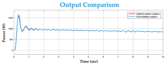
Figure 16.
Output comparison graph.
The potential of the proposed system over a battery-only system is its energy density. The energy consumption and densities obtained from test vehicle simulation with the WLTC homologation drive cycle are illustrated in Figure 17. With the adopted components, the theoretical cost of the hybrid system is approximately estimated to be USD 8000, whereas the estimated cost of the battery-only system is approximately USD 300. The steep difference in cost is due to the high price of fuel cell systems. Slashing further costs in the proposed system lies in the courtesy of future innovations. However, in the current scenario, the proposed system would be cheaper for large volume applications, since extending the capacity of the hybrid system would only require extra tanks.
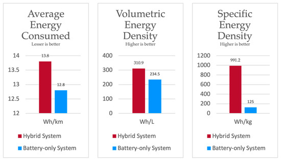
Figure 17.
Comparison of systems.
6. Conclusions
Progress in a direction that involves replacing fossil fuels and polluting battery components is unavoidable in the current scenario of global warming. With hydrogen as a possible future energy carrier, it is essential to develop efficient and robust methods to make hydrogen systems commercial for the future. Replacing input hydrogen with electricity would be a step towards reducing costs. In certain situations, allowing the system to produce its own hydrogen could prove advantageous considering the cost of transporting hydrogen. Eliminating the usage of hydrogen as input fuel by utilising electricity to charge a system to produce its own hydrogen could entirely cut down the costs of transporting hydrogen in sophisticated tank systems and the capital required for erecting fuel stations.
It is important to mention that the designed system has its downsides. It does not include the dynamic parameters of the electrolyser and fuel cell stacks. It does not consider the losses and energy requirements of tanks used to store the fluids. It charges slower as compared with a battery-only storage system. The system cannot be visualized for replacing a battery in small-scale applications, such as smartphones. Nevertheless, to compensate for a few downsides, the proposed system’s modelling is designed with considerably lower efficiencies. However, it is worth noting that higher efficiency designs are achieved on the industrial scale, thus, still widening the potential for the proposed system topology.
With respect to the focus in this paper, i.e., only on modelling of the proposed system topology, we also attempt to illustrate its potential over a battery-only system. The results exhibit the potential of the system with respect to three different aspects. The dynamic nature of the system is demonstrated, wherein it handles the load and/or charges its components in the presence of a power supply or absence thereof. We compare the system’s output against a battery-only system to showcase its ability to handle a load. In addition, the potential of the sytem is illustrated by calculating the system’s average energy consumed, volumetric energy density, and specific energy density against a battery-only system under a certain test method. With the combined energy density of fuel cells and power density of batteries, the proposed system could conceptually carry larger amounts of energy and yet supply practical loads in spite of its practical inefficiencies. Considering the high initial cost and higher minimum weight in the current scenario, the proposed system is not beneficial in every case. However, it could be theoretically considered beneficial for certain large applications such as in large electric vehicles or high-range electric vehicles, and static applications such as inverter energy storage and energy storage at remote locations with a grid.
Author Contributions
Conceptualization, V.R.; methodology, V.R. and I.; software, V.R.; validation, V.R., I. and S.R.S.; formal analysis, V.R. and I.; investigation, V.R.; resources, I. and S.R.S.; data curation, V.R.; writing—original draft preparation, V.R.; writing—review and editing, V.R., I. and S.R.S.; visualization, V.R.; supervision, I. and S.R.S.; project administration, V.R. and I.; funding acquisition, S.R.S. All authors have read and agreed to the published version of the manuscript.
Funding
This research work was funded by “Woosong University’s Academic Research Funding-2022”.
Data Availability Statement
Not applicable.
Conflicts of Interest
The authors declare no conflict of interest.
Nomenclature
| L1 | Buck converter design inductance (mH) |
| C1 | Buck converter design conductance (μF) |
| Vout | Buck converter output voltage (V) |
| D | Duty cycle |
| fsw | Switching frequency (Hz) |
| ΔIL | Current ripple (A) |
| ΔVout | Voltage ripple (V) |
| En | Nernst voltage (V) |
| TFC | Fuel cell operating temperature (T) |
| z | Number of moving electrons |
| F | Faraday’s constant |
| PH2 | Partial pressure of hydrogen (atm) |
| PO2 | Partial pressure of oxygen (atm) |
| F | Faraday’s constant |
| EOC | Open circuit voltage (V) |
| KC | voltage constant at nominal condition |
| E | Fuel Cell Voltage Source (V) |
| A | Tafel Slope (V) |
| iO | Exchange current (A) |
| Td | Response time (s) |
| VFC | Fuel Cell output voltage (V) |
| Rohm | Internal resistance (Ω) |
| α | Charge Transfer Coefficient |
| VH | Amount of Hydrogen produced by Electrolyser (mL/min) |
| Vm | Molar volume of hydrogen |
| R | Universal gas constant (J mol/K) |
| TEL | Operating temperature of electrolyser (C) |
| PEL | Operating pressure of electrolyser (atm) |
| Pt | Hydrogen tank pressure (Pascals) |
| Pti | Hydrogen tank initial pressure (Pascals) |
| ZC | Compressibility Factor |
| NH2 | Amount of hydrogen fed to the tank (mL/min) |
| Tt | Temperature of tank (K) |
| MH2 | Molar mass of hydrogen (kg/mol) |
| Vt | Volume of tank (m3) |
| QH2 | Quantity of hydrogen in tank (mL/min) |
| QO2 | Quantity of oxygen in tank (mL/min) |
| QH2O | Quantity of water in tank (mL/min) |
| Hydrogen produced (mL/min) | |
| Hydrogen consumed (mL/min) | |
| Oxygen produced (mL/min) | |
| Oxygen consumed (mL/min) | |
| Water produced (mL/min) | |
| Water consumed (mL/min) | |
| LH2 | Hydrogen loss |
| LO2 | Oxygen loss |
| SH2 | Stochiometric ratio of hydrogen |
| SO2 | Stochiometric ratio of oxygen |
| SH2O | Stochiometric ratio of water |
| NFC | Number of cells in Fuel cell stack |
| IFC | Fuel cell current (A) |
| ηFC | Fuel cell efficiency |
| NEL | Number of cells in Electrolyser stack |
| IEL | Electrolyser current (A) |
| ηEL | Electrolyser efficiency |
| h | Planck’s constant |
| k | Boltzmann constant |
References
- Ashraf Ansari, S.; Khalid, M.; Kamal, K.; Abdul Hussain Ratlamwala, T.; Hussain, G.; Alkahtani, M. Modeling and Simulation of a Proton Exchange Membrane Fuel Cell Alongside a Waste Heat Recovery System Based on the Organic Rankine Cycle in MATLAB/SIMULINK Environment. Sustainability 2021, 13, 1218. [Google Scholar] [CrossRef]
- Möller, M.C.; Krauter, S. Hybrid Energy System Model in Matlab/Simulink Based on Solar Energy, Lithium-Ion Battery and Hydrogen. Energies 2022, 15, 2201. [Google Scholar] [CrossRef]
- Arsalis, A.; Georghiou, G.E.; Papanastasiou, P. Recent Research Progress in Hybrid Photovoltaic–Regenerative Hydrogen Fuel Cell Microgrid Systems. Energies 2022, 15, 3512. [Google Scholar] [CrossRef]
- Aouali, F.Z.; Becherif, M.; Ramadan, H.S.; Emziane, M.; Khellaf, A.; Mohammedi, K. Analytical Modelling and Experimental Validation of Proton Exchange Membrane Electrolyser for Hydrogen Production. Int. J. Hydrogen Energy 2017, 42, 1366–1374. [Google Scholar] [CrossRef]
- Yaïci, W.; Longo, M. Feasibility Investigation of Hydrogen Refuelling Infrastructure for Heavy-Duty Vehicles in Canada. Energies 2022, 15, 2848. [Google Scholar] [CrossRef]
- Almomani, O.; Sayeed, I.; Kolbantseva, D.; Treschev, D.; Trescheva, M.; Anikina, I.; Kolbantsev, Y.; Kalmykov, K.; Aleshina, A.; Kalyutik, A.; et al. Analysis of Technologies for Hydrogen Consumption, Transition and Storage at Operating Thermal Power Plants. Energies 2022, 15, 3671. [Google Scholar] [CrossRef]
- Darras, C.; Sailler, S.; Thibault, C.; Muselli, M.; Poggi, P.; Hoguet, J.C.; Melscoet, S.; Pinton, E.; Grehant, S.; Gailly, F.; et al. Sizing of Photovoltaic System Coupled with Hydrogen/Oxygen Storage Based on the ORIENTE Model. Int. J. Hydrogen Energy 2010, 35, 3322–3332. [Google Scholar] [CrossRef]
- Onar, O.C.; Uzunoglu, M.; Alam, M.S. Dynamic Modeling, Design and Simulation of a Wind/Fuel Cell/Ultra-Capacitor-Based Hybrid Power Generation System. J. Power Source 2006, 161, 707–722. [Google Scholar] [CrossRef]
- Grunow, P. Decentral Hydrogen. Energies 2022, 15, 2820. [Google Scholar] [CrossRef]
- Briguglio, N.; Brunaccini, G.; Siracusano, S.; Randazzo, N.; Dispenza, G.; Ferraro, M.; Ornelas, R.; Aricò, A.S.; Antonucci, V. Design and Testing of a Compact PEM Electrolyzer System. Int. J. Hydrogen Energy 2013, 38, 11519–11529. [Google Scholar] [CrossRef]
- Sridhar, S.; Reddy Salkuti, S. Development and Future Scope of Renewable Energy and Energy Storage Systems. Smart Cities 2022, 5, 668–699. [Google Scholar] [CrossRef]
- Pollet, B.G.; Staffell, I.; Shang, J.L. Current Status of Hybrid, Battery and Fuel Cell Electric Vehicles: From Electrochemistry to Market Prospects. Electrochim. Acta 2012, 84, 235–249. [Google Scholar] [CrossRef]
- Atlam, O.; Kolhe, M. Equivalent Electrical Model for a Proton Exchange Membrane (PEM) Electrolyser. Energy Convers. Manag. 2011, 52, 2952–2957. [Google Scholar] [CrossRef]
- Jia, J.; Li, Q.; Wang, Y.; Cham, Y.T.; Han, M. Modeling and Dynamic Characteristic Simulation of a Proton Exchange Membrane Fuel Cell. IEEE Trans. Energy Convers. 2009, 24, 283–291. [Google Scholar] [CrossRef]
- Sadykov, A.; Kuriqi, A.; Zhang, L.; Liu, Y.; Pei, P.; Liu, X.; Wang, L.; Wan, Y. Variation Characteristic Analysis of Water Content at the Flow Channel of Proton Exchange Membrane Fuel Cell. Energies 2022, 15, 3280. [Google Scholar] [CrossRef]
- Bockris, J.O.M. The Hydrogen Economy: Its History. Int. J. Hydrogen Energy 2013, 38, 2579–2588. [Google Scholar] [CrossRef]
- Yigit, T.; Selamet, O.F. Mathematical Modeling and Dynamic Simulink Simulation of High-Pressure PEM Electrolyzer System. Int. J. Hydrogen Energy 2016, 41, 13901–13914. [Google Scholar] [CrossRef]
- Omran, A.; Lucchesi, A.; Smith, D.; Alaswad, A.; Amiri, A.; Wilberforce, T.; Sodré, J.R.; Olabi, A.G. Mathematical Model of a Proton-Exchange Membrane (PEM) Fuel Cell. Int. J. Thermofluids 2021, 11, 100110. [Google Scholar] [CrossRef]
- Yang, H.; Han, Y.J.; Yu, J.; Kim, S.; Lee, S.; Kim, G.; Lee, C. Exploring Future Promising Technologies in Hydrogen Fuel Cell Transportation. Sustainability 2022, 14, 917. [Google Scholar] [CrossRef]
- Clemens, M.; Clemens, T. Scenarios to Decarbonize Austria’s Energy Consumption and the Role of Underground Hydrogen Storage. Energies 2022, 15, 3742. [Google Scholar] [CrossRef]
- Marchenko, O.V.; Solomin, S.V. The Future Energy: Hydrogen versus Electricity. Int. J. Hydrogen Energy 2015, 40, 3801–3805. [Google Scholar] [CrossRef]
- Gurau, V.; Ogunleke, A.; Strickland, F. Design of a Methanol Reformer for On-Board Production of Hydrogen as Fuel for a 3 KW High-Temperature Proton Exchange Membrane Fuel Cell Power System. Int. J. Hydrogen Energy 2020, 45, 31745–31759. [Google Scholar] [CrossRef]
- Gutiérrez-Martín, F.; Amodio, L.; Pagano, M. Hydrogen Production by Water Electrolysis and Off-Grid Solar PV. Int. J. Hydrogen Energy 2021, 46, 29038–29048. [Google Scholar] [CrossRef]
- Midilli, A.; Ay, M.; Dincer, I.; Rosen, M.A. On Hydrogen and Hydrogen Energy Strategies: I: Current Status and Needs. Renew. Sustain. Energy Rev. 2005, 9, 255–271. [Google Scholar] [CrossRef]
- Mebarki, N.; Rekioua, T.; Mokrani, Z.; Rekioua, D.; Bacha, S. PEM Fuel Cell/Battery Storage System Supplying Electric Vehicle. Int. J. Hydrogen Energy 2016, 41, 20993–21005. [Google Scholar] [CrossRef]
- Meng, G.; Wu, C.; Zhang, B.; Xue, F.; Lu, S. Net Hydrogen Consumption Minimization of Fuel Cell Hybrid Trains Using a Time-Based Co-Optimization Model. Energies 2022, 15, 2891. [Google Scholar] [CrossRef]
- Al Amerl, A.; Oukkacha, I.; Camara, M.B.; Dakyo, B.; Babu, S. Real-Time Control Strategy of Fuel Cell and Battery System for Electric Hybrid Boat Application. Sustainability 2021, 13, 8693. [Google Scholar] [CrossRef]
- Hernán Suárez, S.; Chabane, D.; N’diaye, A.; Ait-Amirat, Y.; Elkedim, O.; Djerdir, A. Evaluation of the Performance Degradation of a Metal Hydride Tank in a Real Fuel Cell Electric Vehicle. Energies 2022, 15, 3484. [Google Scholar] [CrossRef]
- Meloni, E.; Iervolino, G.; Ruocco, C.; Renda, S.; Festa, G.; Martino, M.; Palma, V. Electrified Hydrogen Production from Methane for PEM Fuel Cells Feeding: A Review. Energies 2022, 15, 3588. [Google Scholar] [CrossRef]
- Awasthi, A.; Scott, K.; Basu, S. Dynamic Modeling and Simulation of a Proton Exchange Membrane Electrolyzer for Hydrogen Production. Int. J. Hydrogen Energy 2011, 36, 14779–14786. [Google Scholar] [CrossRef]
- Pascuzzi, S.; Sotirios Anifantis, A.; Blanco, I.; Mugnozza, G.S.; Rosen, M.A. Electrolyzer Performance Analysis of an Integrated Hydrogen Power System for Greenhouse Heating. A Case Study. Sustainability 2016, 8, 629. [Google Scholar] [CrossRef]
- Ceylan, C.; Devrim, Y. Design and Simulation of the PV/PEM Fuel Cell Based Hybrid Energy System Using MATLAB/Simulink for Greenhouse Application. Int. J. Hydrogen Energy 2021, 46, 22092–22106. [Google Scholar] [CrossRef]
- Van Leeuwen, R.P.; Boerman, A.E.; Schaefer, E.W.; Hoogsteen, G.; Hajimolana, Y.S. Model Supported Business Case Scenario Analysis for Decentral Hydrogen Conversion, Storage and Consumption within Energy Hubs. Energies 2022, 15, 2065. [Google Scholar] [CrossRef]
- International Renewable Energy Agency. Green Hydrogen Cost Reduction; IRENA: Abu Dhabi, United Arab Emirates, 2020; ISBN 9789292602956. [Google Scholar]
- Albarghot, M.; Rolland, L. MATLAB/Simulink modelling and experimental results of a PEM electrolyzer powered by a solar panel. In Proceedings of the 2016 IEEE Electrical Power and Energy Conference (EPEC), Ottawa, ON, Canada, 12–14 October 2016; pp. 1–6. [Google Scholar]
- Yousfi-Steiner, N.; Moçotéguy, P.; Candusso, D.; Hissel, D. A Review on Polymer Electrolyte Membrane Fuel Cell Catalyst Degradation and Starvation Issues: Causes, Consequences and Diagnostic for Mitigation. J. Power Sources 2009, 194, 130–145. [Google Scholar] [CrossRef]
- Venkatesh, G.; Gnanamoorthy, R.; Okazaki, M. Fretting Wear Behaviour of Nickel Foam Struts Used in Fuel Cell Applications. Proc. Inst. Mech. Eng. Part J J. Eng. Tribol. 2022, 236, 144–155. [Google Scholar] [CrossRef]
- Furfari, S.; Clerici, A. Green Hydrogen: The Crucial Performance of Electrolysers Fed by Variable and Intermittent Renewable Electricity. Eur. Phys. J. Plus 2021, 136, 509. [Google Scholar] [CrossRef]
- Ho, N.X.; Nguyen, D.V. Experimental Analysis of the Performance Characteristics of the Regenerative Fuel Cell System Based on Serpentine Flow-Field Design. IOP Conf. Ser. Mater. Sci. Eng. 2021, 1117, 12031. [Google Scholar] [CrossRef]
- Yuan, X.; Cai, Y. Forecasting the Development Trend of Low Emission Vehicle Technologies: Based on Patent Data. Technol. Forecast. Soc. Chang. 2021, 166, 120651. [Google Scholar] [CrossRef]
- Eisapour, A.H.; Eisapour, M.; Talebizadehsardari, P.; Walker, G.S. An Innovative Multi-Zone Configuration to Enhance the Charging Process of Magnesium Based Metal Hydride Hydrogen Storage Tank. J. Energy Storage 2021, 36, 102443. [Google Scholar] [CrossRef]
- Niermann, M.; Timmerberg, S.; Drünert, S.; Kaltschmitt, M. Liquid Organic Hydrogen Carriers and Alternatives for International Transport of Renewable Hydrogen. Renew. Sustain. Energy Rev. 2021, 135, 110171. [Google Scholar] [CrossRef]
- Güther, V.; Otto, A. Recent Developments in Hydrogen Storage Applications Based on Metal Hydrides. J. Alloys Compd. 1999, 293–295, 889–892. [Google Scholar] [CrossRef]
- Motapon, S.N.; Tremblay, O.; Dessaint, L.-A. Development of a Generic Fuel Cell Model: Application to a Fuel Cell Vehicle Simulation. Int. J. Power Electron. 2012, 4, 505. [Google Scholar] [CrossRef]
- Qin, H.; Deng, Z.; Li, X. Cooperative Control of a Steam Reformer Solid Oxide Fuel Cell System for Stable Reformer Operation. Energies 2022, 15, 3336. [Google Scholar] [CrossRef]
- Buck Converter Design. Available online: https://www.mouser.de/pdfdocs/BuckConverterDesignNote.pdf (accessed on 22 April 2022).
- Dere, A.A.; Singh, M.; Thakan, A.; Singh, H. Structural Optimization of Go-Kart Chassis by Geometrical Modifications Based on Modal Analysis. ARPN J. Eng. Appl. Sci. 2019, 14, 3234–3240. [Google Scholar]
- Ballard Power Systems® Nexa 1.2 KW Fuel Cell. Available online: http://heliocentris.com/products/ballard.html (accessed on 16 September 2022).
- Exicom® 2 kWh Li-Ion Battery. Available online: https://www.exicom-ps.com/battery-intro.html?id=divCube4 (accessed on 16 September 2022).
- Bosch® 750 Wh Battery. Available online: https://www.bosch-ebike.com/en/products/batteries (accessed on 16 September 2022).
- Quantum Fuel Systems® 1 kg Hydrogen Tank. Available online: https://www.qtww.com/wp-content/uploads/2019/06/H2-Tank-Specifications-June-2019-All-Tanks-1.pdf (accessed on 16 September 2022).


Publisher’s Note: MDPI stays neutral with regard to jurisdictional claims in published maps and institutional affiliations. |
© 2022 by the authors. Licensee MDPI, Basel, Switzerland. This article is an open access article distributed under the terms and conditions of the Creative Commons Attribution (CC BY) license (https://creativecommons.org/licenses/by/4.0/).