Abstract
The need for electrical energy means batteries have a critical role in technological developments in the future. One of the most advanced types of batteries is the lithium-ion battery. The conventional charging system has the disadvantage of taking a relatively long time, so the battery temperature is high. Therefore, a charging method that can shorten the charging time and extend battery life is needed. Some contributions of the paper are the design and prototype of a buck-boost converter for dual-mode lithium-ion battery charging (buck and boost mode) and the implementation of the Multi-Step Constant Current Method (MSCC) algorithm with an optimal charging pattern (OPT) to perform fast charging under voltage, current limit, and temperature monitoring. The test results showed that the proposed charging system prototype has an accuracy of 99.93% for the voltage sensor and 98.86% for the current sensor, whereas the precision of voltage and current sensors are 98.60% and 99.34%, respectively. The proposed method took 45 min to charge the 2-series (2S) and 4-series (4S) batteries. Compared to the CCCV method, the charging time of the MSCC method was 18.18% faster. In terms of battery temperature, MSCC had a lower peak temperature compared to CCCV by 1.5% and 1.25% for 2S and 4S, respectively.
1. Introduction
The need for electrical energy makes batteries critical as energy storage systems. It is widely used in many aspects nowadays, such as storing energy from renewable energy resources [1], robotics [2], and electric vehicles [3,4,5]. In other words, battery technology will play a critical role in future technological development [6]. One of the most advanced batteries is the lithium-ion battery. It has a high energy density, high specific energy, a good life cycle, low self-discharge, and is environmentally friendly [7,8,9]. Lithium-ion batteries are susceptible to deep discharge or overcharge, affecting their performance and lifespan [10]. Therefore, in applying lithium-ion batteries, the battery charging system must be well designed to get high battery performance and long battery life [11].
There are various battery charging methods, but the most popular is the Constant Current-Constant Voltage (CCCV) method [12]. The CCCV method is widely used in lithium-ion battery charging because of its simplicity and easy application [13,14]. The CCCV method consists of two different types of operations. The battery is charged at a constant current during CC charging mode until a particular upper voltage limit is reached (cut-off). The cut-off is usually set as 4.2 V for Li-ion batteries. In CV mode, charging is carried out by maintaining the voltage at the cut-off threshold, and then the current decreases. The charging process will be terminated when the current reaches a particular value (usually 0.02 C or 0.052 A) since the battery is considered fully charged. Although more than 80% of the battery capacity is filled by CC mode charging, about 50% of the total charging time is taken up by CV mode charging. The CV mode prolongs charging time, which makes it unsuitable for fast charging applications [15] and causes the battery temperature to increase dramatically, which reduces battery life [16,17]. Several filling methods have been developed in the literature to overcome the shortcomings of the CC-CV method. One of them is the Multi-Step Constant current (MSCC) method.
The MSCC charging method consists of several stages of CC mode. The current amplitude is applied differently at each stage until the battery voltage reaches its threshold. In the MSCC charging method, the CV period is replaced by a CC charging period, with some current amplitudes gradually reduced [18]. Therefore, several stages of CC mode from the MSCC charging profile are applied until the maximum charging voltage is reached. The disconnection voltage is applied using a charging pattern controlled via feedback from the battery voltage sensors. The pattern is terminated when the measured battery voltage reaches the cut-off level. The main advantage of MSCC is that the current rate can be adjusted during the charging process; it also limits cell degradation and reduces the charging time [19].
MSCC filling has higher efficiency and decreases the temperature rise compared to the conventional CCCV method [20]. Higher reliability and longer service life can be achieved using the MSCC method due to eliminating the CV filling cycle [15]. The MSCC method has proven its advantage over the traditional charging method regarding the charging time and efficiency [21,22]. Moreover, the charging time of MSCC is faster compared to CCCV with the same initial charging current rate [23]. On the other hand, according to [24], it needs proper cooling or temperature protection to limit the rise in battery temperature.
Some researchers have proposed and researched MSCC as a charging algorithm for Li-ion batteries. Rehman et al. [25] proposed an optimization of MSCC using Fuzzy logic and the Salps Swarm Algorithm (SSA) that could charge 19% faster than PSO-optimized MSCC. A programmable battery charger was also employed in the study; however, a detailed explanation of the experiment process was not provided. Wu et al. [24] used a multistage CCCV in different charging temperatures, 25, 0, and −10 °C; this application resulted in the highest charging capacities and shortest charging periods compared to the traditional CCCV. However, the battery tester used was designed without any self-developing method. Khan et al. [11] also used the MSCC method and proved that it has a faster charging time than CCCV by 12%. However, the operation mode in the battery test experiment was not clearly stated; it was unclear whether the test was performed in buck or boost mode. An et al. [26] used MSCC to charge pouch cell batteries and concluded that the MSCC method improves cycle performance and could shorten charging time. Haider et al. [15] proposed Temperature-Compensated-MSCC (TC-MSCC) and stated that traditional MSCCs did not consider the charging temperature and only used voltage cut-off as feedback; thus, using TC-MSCC could reduce the peak temperature. However, the research did not mention how to find the pattern of the charging current.
Meanwhile, Zhang et al. [27] used GA to find the optimal current step in MSCC with temperature as a constraint and charging time as the objective function. The experimental result showed that the applied method could reduce the temperature rise by up to 46.4% and charging time by up to 4.2% compared to MSCC without optimization. However, the study only focused on the development of the charging algorithm and not on the prototyping process. Wang et al. [28] used PSO to find the optimal current stage of the five-stage constant-current (5SCC). The experimental result verified that the method could improve the charging time and charging efficiency by 15.6% and 0.47%, respectively. However, the drawback was found that the SoC charging was lower by 2.5%. In addition, Mathieu et al. [29] used numerical optimization for MSCC. An electro-thermal model of the battery was used for the optimization process. The objective was to minimize the charging time with constraints of charged capacity, temperature, and current. Compared to the CCCV method, the Mathieu method could decrease the charging time without increasing the degradation.
A design and development of a charging system with a buck-boost mode converter will be explained in detail. Moreover, the main contributions of the paper can be briefly listed as follows:
- (1)
- This paper presents the design and prototype of a buck-boost converter for lithium-ion battery charging with dual-mode: buck and boost mode.
- (2)
- The MSCC algorithm with optimal charging pattern (OPT) was used to perform fast charging under voltage, current limit, and temperature monitoring.
- (3)
- Detailed comparisons of experimental results with the conventional CCCV were presented.
2. Materials and Methods
2.1. Battery State of Charge (SoC)
The SoC of a battery is defined as the ratio of current capacity Q(t) to nominal capacity Q(n) [30]. The nominal capacity is given by the manufacturer and represents the maximum amount of charge that can be stored in the battery. The SoC can be defined using (1). One SoC estimation method that is highly precise and simple is the open-circuit voltage (OCV) [31]. OCV is an estimation of battery SoC by calculating the battery’s open-circuit voltage (voltage when the battery current is zero). The basic formula for the OCV method can be seen in (2) [32], where A0 is the terminal voltage at SoC = 0% (Vmin). Meanwhile, A1 is the voltage difference between SoC = 100% and SoC = 0% (Vmax − Vmin). The lithium-ion battery used in this research was a Sony VTC4 18650, with its specifications as listed in Table 1.

Table 1.
Li-ion battery specification [33].
2.2. Buck-Boost Converter
Buck-boost converter is a combination of a buck converter and a boost converter. Buck-boost converter is a DC-DC converter whose output voltage can be greater or less than the input voltage. Figure 1 is a general buck-boost converter circuit. The switching process in this converter is also ignited by Pulse Width Modulation (PWM) as a duty cycle setting, which profoundly influences the size of the output voltage of the buck-boost converter. There are two PWMs used for switching, namely PWM1 to generate a duty cycle in buck mode and PWM2 to generate a duty cycle in boost mode.
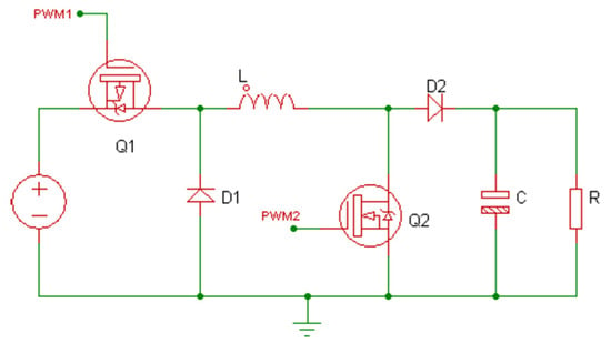
Figure 1.
Topology of the buck-boost converter.
One of the components that must be considered in manufacturing the buck-boost converter is the LC filter, which is crucial for leveling the resulting switching pulses. The value of the inductor will affect the operation of the buck-boost converter. The inductor current must remain continuous for one period to operate in a continuous region. The minimum required inductor value is determined using (3) and (4) for buck and boost modes, where D, f, and R, are duty cycle, frequency, and resistor values, respectively.
The output voltage cannot be perfectly constant. The output voltage has ripples, primarily due to the characteristic of a capacitor; it charges and discharges continuously. A capacitor with a particular value is required so that the resulting voltage ripple is small. The minimum required capacitor value is determined using (5) and (6) for buck and boost mode. Meanwhile, Table 2 shows the specification of the proposed charger design.

Table 2.
Design specification of the proposed buck-boost converter.
2.3. Multi-Step Constant Current (MSCC)
MSCC method works by dividing the charging current into some steps. It is also called five steps charging since the resulting charging process has five steps. According to Gao et al. [34], this method is model-free, easy to implement, and performs better than the CCCV method.
There are three essential parameters in designing an MSCC-based charging system: the number of steps, the current value in each step, and the duration of each step. However, finding the optimal step is difficult and time-consuming [35]. The MSCC charging process is illustrated in Figure 2.
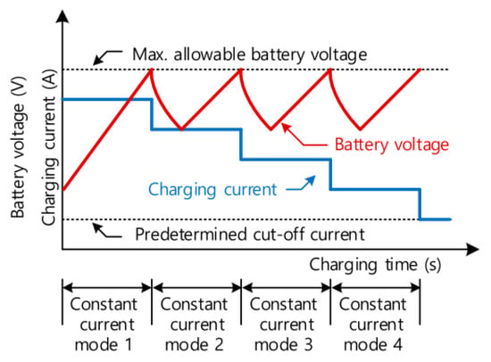
Figure 2.
MSCC with five steps [36].
In this research, the optimal charging pattern (OCP) proposed by Khan and Choi [10] was adopted to overcome issues in the applied MSCC, precisely the five-step MSCC. Thus, the first and last current values can be determined based on the maximum current and battery capacity. Meanwhile, the second, third, and fourth current step values are determined based on (7).
2.4. Proposed System
There are two steps in the system design process: hardware design and software design. The hardware design involves developing a buck-boost converter prototype and manufacturing a monitoring system for the current, voltage, and temperature sensors. Meanwhile, the software design consists of programming a sensor reading and SoC on the battery, and then displaying them on an OLED screen. After that, the operation mode will be selected, whether in a buck or a boost mode.
The system block diagram is shown in Figure 3. Arduino was chosen as the controller with three sensors: current, voltage, and temperature. Whereas Figure 4 shows the schematic for the simulation. The flow diagram of the proposed method is presented in Figure 5. The process started with a sensor reading and calculating the SoC, then displaying the results in an OLED. The next step was determining the boost or buck mode selection based on the voltage detected. The buck mode would be operated if the voltage was lower than 14.4. Otherwise, the system would select the boost mode.
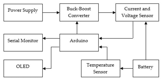
Figure 3.
Block diagram of the proposed system.
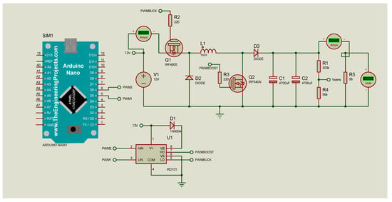
Figure 4.
Buck-boost converter simulation circuit.
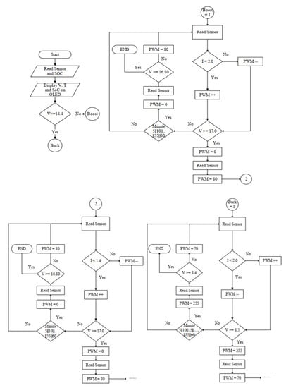
Figure 5.
System working flow.
The system would enter the boost operation mode if the boost mode was selected. When the system selected the boost mode and entered the boost operation mode, the sensor continued to read the measurement. Then, the measured current would be compared to the threshold. If the current measured were lower than the current of the first step, the PWM would increase. Table 3 presents the list of current values of each step in the research.

Table 3.
Current step for MSCC method.
The voltage sensor informed the measurement of the battery’s voltage. If the measured voltage exceeded the threshold value, the PWM would be set to zero, and the next step would be continued. The threshold for 4S (four series) batteries used in this research was 17 V. On the other hand, if the measured voltage was lower than the threshold, the system would stay operating at the first current step. The voltage reading was performed every five minutes. The same logical procedure was applied to the second, third, fourth, and fifth steps.
In the buck mode, the logic flow was still the same; the only difference was in the values of voltage threshold and PWM. In this mode, the increase in the charging voltage was performed by lowering the PWM value. The second until the fifth step of buck mode was the same as its first step.
2.5. Sensor Accuracy and Precision
The sensor reading test was aimed to determine whether the reading results of the sensor match the actual measurement. Any difference between the sensor reading and the measuring instrument would be used as a reference for programming and calibrating. After calibrating the voltage reader, the level of accuracy and precision would be tested. The level of accuracy was represented by the root mean square error (RMSE), as shown in (8). The smaller the RMSE, the better the level of accuracy. The level of the precision test was represented by the relative standard deviation (RSD) of repeatability (9), where n is the number of samplings, x is sensor measurement, is the multimeter measurement, is the means of sensor measurement data, and SD is the standard deviation. Meanwhile, three types of sensors were used: voltage, current, and temperature sensors.
A voltage sensor test was performed by assembling a voltage sensor in parallel with a multimeter and then connecting them to a voltage divider circuit using a resistor. The voltage measurement was carried out according to (10).
The sensor used to measure the electrical current was ACS712-05A. This sensor had a maximum current reading capability of 5 A. The ACS712-5A current sensor reading sensitivity was 185 mV/A. The measured electrical current was determined using (11).
Battery temperature measurement was measured by placing a temperature sensor on the battery. In a 2-series battery, the temperature sensor was placed in the middle of the batteries. The temperature sensor placement was designed to measure the two batteries simultaneously. While in a 4-series battery, the temperature sensor was placed in the middle of the batteries. Figure 6 shows the placement of the temperature sensor.
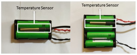
Figure 6.
Battery temperature measurement.
3. Results and Discussion
3.1. Buck-Boost Converter Simulation
A simulation carried out with the designated circuit in Figure 4 obtained several samples of voltage measurements. This simulation assessed the relationship between the duty cycle and the input–output voltage in buck and boost modes. The buck mode and boost mode test results are listed in Table 4. It shows that with the same input value when the duty cycle is increased, the buck mode has the lower output; at the same condition, the boost mode has the higher output. It proves that the proposed charger can work well in the simulation.

Table 4.
Simulation result.
3.2. Hardware Testing
Figure 7 is an image of the proposed battery charging system design, in which the components were installed following the circuit design schematic. The following is a description of each component installed in the system:
| A: PNP MOSFET | F: Inductor | K: OLED |
| B: Capacitor | G: NPN MOSFET | L: Diode |
| C: Regulator 5 V | H: Voltage Sensor | M: Current Sensor |
| D: Supply Input | I: Temperature Sensor | N: Buck-Boost output |
| E: Driver MOSFET (IR2101) | J: Arduino Nano |
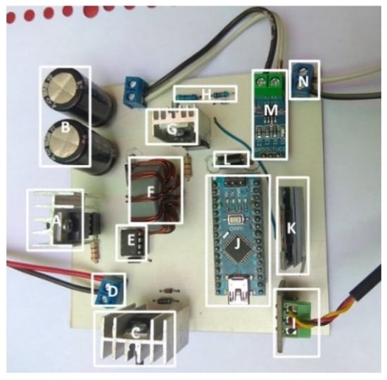
Figure 7.
System hardware.
3.2.1. Sensor Accuracy and Precision
The accuracy of voltage and current sensors were represented by the root mean square error (RMSE). The value of RMSE was proportional to the accuracy level; the smaller the RMSE value, the better the level of accuracy. Figure 8 and Figure 9 show the test results of the voltage sensor and the current sensor, respectively, which describe the sensors’ accuracy.
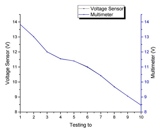
Figure 8.
Test results of the voltage sensor.
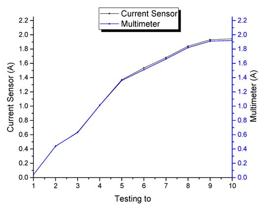
Figure 9.
Test results of the current sensor.
Based on Figure 8, the percentage of error value readings on the multimeter and voltage sensor had an error value of 0.07% RMSE, so the voltage sensor reading had an accuracy of 99.93%. Meanwhile, Figure 9 shows a comparison of current measurements between the current sensor measurement and a multimeter. The error value (RMSE) on the current sensor used was 1.14%, so the current sensor reading had an accuracy of 98.86%.
The precision test was performed by measuring voltage and current sensor measurements fifty times repeatedly. Based on the precision test results, the standard deviation of voltage and current sensors are 0.149 and 0.007, respectively. The RSD of each sensor is 1.399% and 0.659%. In other words, the voltage and the current sensor had a precision of 98.60% and 99.34%, respectively.
3.2.2. Buck-Boost Testing
The test for a buck-boost converter was performed by varying the duty cycle as an input to obtain a varying output voltage. The test was divided into two stages, buck and boost modes. A load of 220 Ω was given to measure the output voltage. The test aimed to determine whether the circuit was running well and could be utilized properly in a battery charging system.
Test results for the buck-boost converter operating in a buck mode are listed in Table 5. The duty cycle was set from 0% to 90%. The highest output voltage was obtained when the duty cycle was 0%, which was 11.95 V. The highest efficiency (87.97%) was also obtained at the same duty cycle. Meanwhile, the smallest output voltage (3.90 V) and the smallest efficiency (18.62%) were obtained at a 90% duty cycle.

Table 5.
Test result buck mode.
Table 6 shows the test results for the boost mode, with the duty cycle being set from 0% to 70%. The highest output voltage was obtained when the duty cycle was 70%, which was 27.9 V. The smallest output voltage was obtained at 0% duty cycle and measured as 11.95 V. Moreover, the lowest efficiency was obtained at 70% duty cycle (51.65%). Meanwhile, the highest efficiency was obtained at 30% duty cycle (89.11%).

Table 6.
Test result boost mode.
3.2.3. Comparison between CCCV and MSCC
- (a)
- Charging 2S and 4S batteries
Figure 10 shows the charging processes of 2-series (2S) and 4-series (4S) batteries with CCCV and MSCC methods. The utilization of a 2S battery was to perform the buck mode, whereas the 4S battery was to perform the boost mode of the charger. According to the figure, both voltage and current show a constant pattern before the drastic change in the CCCV method. On the other side, in the MSCC method, the charging current’s pattern was like a step. The overall results showed a similar charging time for both 2S and 4S; the MSCC method required 45 min to fully charge the battery, which was reasonably faster than the CCCV method (55 min). A more comprehensive and detailed analysis will be provided in the next part.
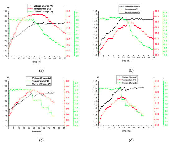
Figure 10.
Charging process: (a) 2S-CCCV; (b) 4S-CCCV; (c) 2S-MSCC; (d) 4S-MSCC.
- (b)
- Charging voltages
A comparison of charging voltage using CCCV and MSCC methods is shown in Figure 11. Based on Figure 11a, the voltage would slowly increase to stabilize the charging current at 2 A when charging a 2S battery using the CCCV method. When the voltage reached the cut-off at 8.51 V, the charging system entered CV mode, and the voltage would be stable at 8.51 V with a voltage ripple of 0–0.03 V.
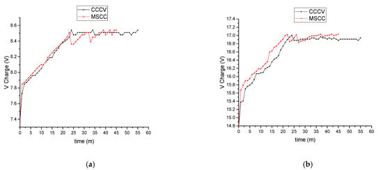
Figure 11.
Charging voltage: (a) 2S; (b) 4S.
Meanwhile, the initial charging voltage using the MSCC method will increase slowly to stabilize the charging current at 2 A, as shown in Figure 11a. The charging system continued to the second step when the voltage reached the cut-off at 8.51 V, with a decreasing pattern, following the pattern of the charging current, which would later be stable at 1.42 A. After the charging current reached the second step of the charging strategy, the voltage rose again until it reached the second cut-off at 8.51 V. Then, the charging system continued to the third step of the fast-charging strategy, and the voltage would be dropped again until the charging current reached the next value of the current’s threshold. When the voltage reached the third cut-off at 8.54 V, the system then entered the fourth step of the fast-charging strategy with a decreasing trend until the charging current reached 0.73 A. The charging process would be continued until the charging voltage reached the fourth cut-off at 8.54 V, with a current of 0.52 A. At the fifth step of the charging strategy, the voltage would be maintained to stabilize the charging current at 0.52 A until the battery became fully charged. At this stage, the battery temperature decreased as the charging stages changed.
Similarly, the pattern of the charging voltage for the 4S battery is shown in Figure 11b. In CCCV mode, the voltage would increase slowly to stabilize the charging current at 2 A. After reaching the cut-off voltage at 17.00 V, the charging system entered CV mode, and the voltage would be stable at 16.94 V with a ripple of 0–0.06 V.
In the MSCC mode, the initial charging voltage will increase slowly as well to stabilize the charging current at 2 A. The results were very much similar to the application for the 2S battery. The only difference was the cut-off value of the voltage. In the 4S battery, the voltage cut-off was around 17 V. The pattern of the charging voltage was similar to the previous results of the application for a 2S battery.
According to Figure 11a,b, the charging voltage pattern for CCCV was considered reasonably smooth, whereas MSCC had a saw-tooth pattern since the charging current was changed after reaching the voltage threshold. However, the MSCC method performed a faster charging completion than the CCCV method based on the time taken by the batteries to be fully charged.
- (c)
- Charging Current
In the application of the CCCV method for 2S batteries, the charging current was stable at ±2 A until the 26th minute; this indicates that the charging system was in the CC mode. Then, the charging current slowly dropped, indicating that the charging system was in CV mode, as shown in Figure 12a. Similarly, in the application of the MSCC method, the charging current was stable at ±2 A until the 23rd minute; this indicates that the charging system was in the first step of the CC mode. Then, the charging current was lowered and stabilized at ±1.4 A until the 32nd minute, indicating that the charging system was in the second step. The current was reduced and stabilized at ±1.0 A until the 39th minute, indicating the third step of the fast-charging strategy. Later, the charging current was lowered and stabilized at ±0.73 A until the 42nd minute, indicating that the charging system was in the fourth step. The charging current was then lowered and re-stabilized at ±0.52 A until the battery was fully charged at the 45th minute, which was in the fifth stage.
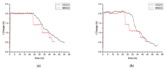
Figure 12.
Charging current: (a) 2S; (b) 4S.
Meanwhile, Figure 12b shows the results for applying both methods for 4S batteries. When the battery was charged using the CCCV method, the charging current was stable at ±2 A until the 24th minute; this indicates that the charging was in the CC mode. After that, the current slowly dropped, indicating the charging system operated in CV mode. Using the MSCC method, the charging current was stable at ±2 A until the 23rd minute, which means the charging system was at the first step of the CC mode. At the 23rd minute, the charging current was reduced and stabilized at ±1.4 A until the 37th minute, indicating that the charging system was in the second step of the fast-charging strategy. After that, the charging current was reduced and stabilized at ±1.0 A until the 42nd minute, in the third stage. The charging current was reduced and stabilized at ±0.73 A until the 42nd minute, indicating that the charging is in the fourth stage. Eventually, the charging current was lowered and stabilized at ±0.52 A until the battery was fully charged at the 45th minute. This was considered the fifth step of the fast-charging strategy using the MSCC method.
Unlike the pattern of charging voltage, some differences can be clearly seen in the patterns of charging current for both methods. The charging current of the MSCC method had a step-like pattern that prevented a drastic change in current drop. However, in the CCCV method, the charging current had a drastic drop in its pattern. In these results, the current in the MSCC method was lower than in the CCCV method. This phenomenon does not mean the MSCC charging current capacity is lower than CCCV; this happens due to battery voltage in MSCC reaching the cut-off voltage (8.4 V for 2S and 16.8 for 4S); therefore, based on the MSCC algorithm, the current value is changed to the next step value. If the battery voltage has not reached the cut-off voltage yet, the MSCC current will continue at the determined current step, which will be higher than the CCCV current.
- (d)
- Battery temperature
A detailed comparison of the battery temperature in the charging system for a 2S battery using CCCV and MSCC methods is shown in Figure 13a. According to the figure, the battery temperature of a charging system using the CCCV method rose slowly in CC mode. Then, after reaching 32.7 °C, which was the highest temperature, the battery temperature was maintained stably for a while before decreasing in CV mode at the 33rd minute.
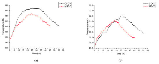
Figure 13.
Battery temperature: (a) 2S; (b) 4S.
Meanwhile, in the MSCC method, the battery temperature also rose slowly in the first step of the CC mode but was not as drastic as in the CCCV method. The battery temperature reached its maximum, which was 32.2 °C at the 26th minute, and then decreased as the mode changed. The decrease in battery temperature in the MSCC method was performed faster than in the CCCV method, as the temperature was not maintained at the same value for a long time.
Figure 13b was a detailed comparison of the battery temperature for charging 4S batteries. Similar to the results of applying the CCCV method for charging the 2S battery, the battery’s temperature increased slowly in CC mode, was stable at its maximum (32 °C) for a while, and then decreased during the CV mode at the 32nd minute. The pattern of the battery temperature while charging the 4S battery using the MSCC method was also similar to the results of charging the 2S battery. The battery temperature also increased slowly at the first step of CC mode; however, the battery temperature was slightly higher than the results of the CCCV method during this period. Then, the battery temperature reached its maximum at the 23rd minute, which was 31.6 °C, and then decreased as the mode changed. During this period, the battery temperature was lower than the results of the CCCV method.
- (e)
- Battery Voltage
The difference between the charging voltage and the battery voltage is that the charging voltage is measured when there is a current flow to the battery from the charger. In contrast, the battery voltage is measured every 5 min when the charger is disconnected since the battery current must be zero to estimate SoC using the OCV method. Figure 14 shows the comparison of the battery voltage among the applications of CCCV and MSCC methods. Figure 14a shows the results for charging 2S batteries. In the CCCV method, the initial battery voltage was 7.37 V, and the battery voltage slowly increased to reach 8.42 V. This indicates that the charging system had successfully charged the battery. Since the current entering the battery was restricted in the CV mode, the battery voltage would rise slowly.
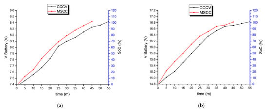
Figure 14.
Battery voltage: (a) 2S; (b) 4S.
Whereas when charging with MSCC, with an initial battery voltage of 7.38 V, the battery voltage increased faster with a higher voltage than the results of the CCCV method. The battery voltage rose slowly in the fourth stage due to the small charging current. The battery voltage did not exceed 8.4 V; this indicates that the system had successfully charged the battery fully and managed to keep the battery from overcharging.
Similarly, the battery voltage of a charging system for the 4S battery using CCCV and MSCC methods increased slowly and successfully reached 16.8 V, with initial voltages of 14.77 and 14.78 V, respectively. According to Figure 14b, in applying the CCCV method to charge 4S batteries, the battery voltage rose slowly when entering the CV mode since the current to the battery was reduced. In different ways, during the fourth stage of charging using the MSCC method, the battery voltage rose slowly because the current entering the charging was small. The battery voltage did not exceed 16.8 V; this indicates that the system has fully charged the battery and managed to keep the battery from overcharging. The charging time taken to charge 4S batteries was the same as for 2S batteries.
4. Conclusions
The multi-step constant current (MSCC) design was divided into two stages: hardware design and software design. The hardware design was performed by implementing a buck-boost converter system using current and voltage sensors as feedback from the charging system. Meanwhile, the software design was performed by programming the algorithm and then implementing it on the Arduino Nano microcontroller. The test results showed that the proposed charging system prototype had an accuracy of 99.93% and 98.86% for the voltage sensor and current sensor, respectively. Moreover, the precision of voltage and current sensors are 98.60% and 99.34%, respectively. According to the experimental results, the proposed design could maintain a stable current at each specified charging stage on the cut-off voltage that had been reached. The charging system managed to keep the battery voltage from exceeding the safe limit. In the 2-series battery, the battery voltage was 8.4 V, while the battery voltage in the 4-series battery was 16.8 V. The charging time to fully charge a battery using the MSCC method for 2-series and 4-series batteries was 45 min, while it took 55 min using the conventional CCCV method. Therefore, the MSCC method was reasonably faster than the CCCV method; by 18.18%. In terms of battery temperature, MSCC had a lower peak temperature compared to CCCV, by 1.5% and 1.25% for 2S and 4S, respectively.
Author Contributions
Conceptualization, M.N. and I.I.; Data curation, B.I.; Formal analysis, B.I.; Methodology, M.N. and I.I.; Validation, H.M.; Writing—original draft, H.M.; Writing—review and editing, A.M. All authors have read and agreed to the published version of the manuscript.
Funding
This research activity is supported through funding from the Ministry of Education, Culture, Research and Technology Through Penelitian Unggulan Terapan UNS according to the contract NUMBER: 254/UN27.22/PT.01.03/2022.
Data Availability Statement
Not applicable.
Conflicts of Interest
The authors declare no conflict of interest.
References
- Abedini Rizi, A.; Rezaei, A.; Ghorbani Rizi, M.; Aliakbari Rizi, M. Design a New Multiport DC-DC Converter to Charge an Electric Car. Int. J. Robot. Control Syst. 2022, 2, 87–96. [Google Scholar] [CrossRef]
- Sreenivas Rao, M.V.; Shivakumar, M. IR based auto-recharging system for autonomous mobile robot. J. Robot. Control 2021, 2, 244–251. [Google Scholar] [CrossRef]
- Amifia, L.K. Direct Comparison Using Coulomb Counting and Open Circuit Voltage Method for the State of Health Li-Po Battery. J. Robot. Control 2022, 3, 455–463. [Google Scholar] [CrossRef]
- Mohammed, A.A.; Abdullahi, A.; Ibrahim, A. Development of a prototype autonomous electric vehicle. J. Robot. Control 2021, 2, 559–564. [Google Scholar] [CrossRef]
- Duan, J.; Tang, X.; Dai, H.; Yang, Y.; Wu, W.; Wei, X.; Huang, Y. Building Safe Lithium-Ion Batteries for Electric Vehicles: A Review; Springer: Singapore, 2020; Volume 3, ISBN 0123456789. [Google Scholar]
- Patnaik, L.; Praneeth, A.V.J.S.; Member, S.; Williamson, S.S. A Closed-loop Constant-temperature Constant-voltage Charging Technique to Reduce Charge Time of Lithium-ion Batteries. IEEE Trans. Ind. Electron. 2018, 66, 1059–1067. [Google Scholar] [CrossRef]
- Saw, L.H.; Ye, Y.; Tay, A.A. Integration issues of lithium-ion battery into electric vehicles battery pack. J. Clean. Prod. 2016, 113, 1032–1045. [Google Scholar] [CrossRef]
- Rao, Z.; Wang, S.; Zhang, G. Simulation and experiment of thermal energy management with phase change material for ageing LiFePO 4 power battery. Energy Convers. Manag. 2011, 52, 3408–3414. [Google Scholar] [CrossRef]
- Wang, S.; Jin, S.; Bai, D.; Fan, Y.; Shi, H.; Fernandez, C. A critical review of improved deep learning methods for the remaining useful life prediction of lithium-ion batteries. Energy Rep. 2021, 7, 5562–5574. [Google Scholar] [CrossRef]
- Khan, A.B.; Choi, W. Optimal Charge Pattern for the High Performance Multi-Stage Constant Current Charge Method for the Li-Ion Batteries. IEEE Trans. Energy Convers. 2018, 33, 1132–1140. [Google Scholar] [CrossRef]
- Khan, A.B.; Pham, V.; Nguyen, T.; Choi, W. Multistage Constant-Current Charging Method for Li-ion Batteries. In Proceedings of the IEEE Transportation Electrificatin Conf and Expo, Dearborn, MI, USA, 27–29 June 2016; pp. 381–385. [Google Scholar]
- Chen, L.R.; Han, J.Y.; Jaw, J.L.; Chou, C.P.; Liu, C.S. A Resistance-Compensated Phase-Locked Battery Charger. In Proceedings of the 1st IEEE Conference on Industrial Electronics and Applications, Singapore, 24–26 May 2006. [Google Scholar]
- Ashwin, T.R.; Mcgordon, A.; Jennings, P.A. Electrochemical modelling of Li-ion battery pack with constant voltage cycling. J. Power Sources 2017, 341, S39–S47. [Google Scholar] [CrossRef]
- Liu, P.; Chien, L. A High-Efficiency Integrated Multimode Battery Charger with an Adaptive Supply Voltage Control Scheme. IEEE Trans. Power Electron. 2017, 33, 6869–6876. [Google Scholar] [CrossRef]
- Alhaider, M.M.; Ahmed, E.M.; Aly, M.; Serhan, H.A.; Mohammed, E.A.; Ali, Z.M. New Temperature-Compensated Multi-Step Constant-Current Charging Method for Reliable Operation of Battery Energy Storage Systems. IEEE Access 2020, 8, 27961–27972. [Google Scholar] [CrossRef]
- Liu, C.; Chiu, Y.; Liu, Y.; Ho, Y.; Huang, S.; Technology, I. Optimization of a Fuzzy-Logic-Control-Based Five-Stage Battery Charger Using a Fuzzy-Based Taguchi Method. Energies 2013, 6, 3528–3547. [Google Scholar] [CrossRef]
- Dung, L.R.; Chen, C.E.; Yuan, H.F. A robust, intelligent CC-CV fast charger for aging lithium batteries. IEEE Int. Symp. Ind. Electron. 2016, 2016, 268–273. [Google Scholar] [CrossRef]
- Liu, Y.; Hsieh, C.; Luo, Y. Search for an Optimal Five-Step Charging Pattern for Li-Ion Batteries Using Consecutive. IEEE Trans. Energy Convers. 2011, 26, 654–661. [Google Scholar] [CrossRef]
- Duru, K.K.; Karra, C.; Venkatachalam, P.; Betha, S.A.; Anish Madhavan, A.; Kalluri, S. Critical Insights into Fast Charging Techniques for Lithium-Ion Batteries in Electric Vehicles. IEEE Trans. Device Mater. Reliab. 2021, 21, 137–152. [Google Scholar] [CrossRef]
- Serhan, H.A.; Ahmed, E.M. Effect of the Different Charging Techniques on Battery Life-Time: Review. In Proceedings of the 2018 International Conference on Innovative Trends in Computer Engineering (ITCE), Aswan, Egypt, 19–21 February 2018; pp. 421–426. [Google Scholar]
- Amanor-boadu, J.M.; Guiseppi-elie, A.; Sánchez-sinencio, E. Search for Optimal Pulse Charging Parameters for Li-ion Polymer Batteries Using Taguchi Orthogonal Arrays. IEEE Trans. Ind. Electron. 2018, 65, 8982–8992. [Google Scholar] [CrossRef]
- Arabsalmanabadi, B.; Tashakor, N.; Javadi, A.; Al-Haddad, K. Charging techniques in lithium-ion battery charger: Review and new solution. In Proceedings of the IECON 2018—44th Annual Conference of the IEEE Industrial Electronics Society, Washington, DC, USA, 21–23 October 2018; pp. 5731–5738. [Google Scholar]
- Wang, S.C.; Chen, Y.L.; Liu, Y.H.; Huang, Y.S. A fast-charging pattern search for li-ion batteries with fuzzy-logic-based Taguchi method. In Proceedings of the 2015 IEEE 10th Conference on Industrial Electronics and Applications (ICIEA), Auckland, New Zealand, 15–17 June 2015; pp. 855–859. [Google Scholar] [CrossRef]
- Wu, X.; Hu, C.; Du, J.; Sun, J. Multistage CC-CV Charge Method for Li-Ion Battery. Math. Probl. Eng. 2015, 2015, 294793. [Google Scholar] [CrossRef]
- Rehman, F.U.; Mehmood, T.; Iqbal, M.B. Charging Time Reduction Using Optimized Multistage Constant Current Charging Pattern for Lithium Ion Batteries. ITEE J. 2019, 8, 101–109. [Google Scholar]
- An, F.; Zhang, R.; Wei, Z.; Li, P. Multi-stage constant-current charging protocol for a high-energy-density pouch cell based on a 622NCM/graphite system. RSC Adv. 2019, 9, 21498–21506. [Google Scholar] [CrossRef]
- Zhang, Y.; Xu, S.; Wu, T. Multi-stage constant current charging strategy considering SOC intervals and voltage thresholds. Glob. Energy Interconnect. 2022, 5, 143–153. [Google Scholar] [CrossRef]
- Wang, Y.; Li, Y.; Jiang, L.; Huang, Y.; Cao, Y. PSO-based optimization for constant-current charging pattern for Li-ion battery. Chin. J. Electr. Eng. 2019, 5, 72–78. [Google Scholar] [CrossRef]
- Mathieu, R.; Briat, O.; Gyan, P.; Vinassa, J.M. Fast charging for electric vehicles applications: Numerical optimization of a multi-stage charging protocol for lithium-ion battery and impact on cycle life. J. Energy Storage 2021, 40, 102756. [Google Scholar] [CrossRef]
- Chang, W. The State of Charge Estimating Methods for Battery: A Review. ISRN Appl. Math. 2013, 2013, 953792. [Google Scholar] [CrossRef]
- Espedal, I.B.; Jinasena, A.; Burheim, O.S.; Lamb, J.J. Current trends for state-of-charge (SoC) estimation in lithium-ion battery electric vehicles. Energies 2021, 14, 3284. [Google Scholar] [CrossRef]
- Chiasson, J.; Vairamohan, B. Estimating the State of Charge of a Battery. IEEE Trans. Control Syst. Technol. 2005, 13, 465–470. [Google Scholar] [CrossRef]
- Lithium Ion Rechargeable Battery Technical Information. Available online: https://www.powerstream.com/p/us18650vtc4.pdf (accessed on 29 October 2021).
- Gao, Y.; Zhang, X.; Cheng, Q.; Guo, B.; Yang, J. Classification and Review of the Charging Strategies for Commercial Lithium-Ion Batteries. IEEE Access 2019, 7, 43511–43524. [Google Scholar] [CrossRef]
- Brenna, M.; Foiadelli, F.; Leone, C.; Longo, M. Electric Vehicles Charging Technology Review and Optimal Size Estimation. J. Electr. Eng. Technol. 2020, 15, 2539–2552. [Google Scholar] [CrossRef]
- Cho, I.H.; Lee, P.Y.; Kim, J.H. Analysis of the Effect of the Variable Charging Current Control Method on Cycle Life of Li-ion Batteries. Energies 2019, 12, 3023. [Google Scholar] [CrossRef]
Publisher’s Note: MDPI stays neutral with regard to jurisdictional claims in published maps and institutional affiliations. |
© 2022 by the authors. Licensee MDPI, Basel, Switzerland. This article is an open access article distributed under the terms and conditions of the Creative Commons Attribution (CC BY) license (https://creativecommons.org/licenses/by/4.0/).