Abstract
The goal of this study was to figure out how to regulate an induction motor in a hybrid electric vehicle. Conventional combined vector and direct control induction motors take advantage of the advantages of vector control and direct torque control. It is also a method that avoids some of the difficulties in implementing both of the two control methods. However, for this method of control, the statoric current has a great wealth of harmonic components which, unfortunately, results in a strong undulation of the torque regardless of the region speed. To solve this problem, a five-level neutral point clamped inverter was used. Through multilevel inverter operation, the voltage is closer to the sine wave. The speed and torque are then successfully controlled with a lower level of ripple in the torque response which improves system performance. The analysis of this study was verified with simulation in the MATLAB/Simulink interface. The simulation results demonstrate the high performance of this control strategy.
1. Introduction
The major equipment utilized for electromechanical converters worldwide is the induction motor. It is used in most production sectors and contributes to about two-thirds of electrical production in industrial applications [1]. This effort is part of a project to develop a hybrid electric vehicle. The most important advantages of an induction motor are: Its construction is quite simple in nature which does not only contain brushes but also slip rings and commutators. Furthermore, for a hybrid electric vehicle, the induction motor appears to be the ideal option.
Its cost is quite low compared to DC motors with the disadvantages of the brush commutator as well as corrosion and the need for servicing. Therefore, closed-loop induction motors are particularly used for speed-controlled applications [2]. The development of microprocessors and power engineering has led to the implementation of novel techniques for precise control of torque and speed of induction machines [3].
There are generally two types of controls for induction motors. First, there is vector control (VC). In VC, the decoupling of torque and flux control can be guaranteed which makes it possible to control the induction motor linearly like a separately excited DC motor [4]. However, the rotor’s torque and flux are regulated by the stator current decoupled from the d and q axes.
The second alternative command is direct torque control (DTC) [5], which is made up of a pair of hysteresis comparators, a couple of torque and flow calculators, a look-up table, and a voltage source converter [6]. The main interest in DTC is based on certain advantages compared to conventional vector drives, such as the control without the use of current loops, the transmission does not require coordinate conversion between the stationary and synchronous loops, and the use of a pulse-width modulator (PWM) is not necessary [7]. However, this type of drive usually poses major problems, such as the need to estimate the flux and torque and then vary the switching frequency. The literature on this variation is extensive, and several techniques are suggested to decrease the impact of this variety [8].
The objectives of combining the performance of vector control and direct torque control are speed and accuracy which resulted in a new control method that has already been defined and proposed in [9,10,11,12] under the name of combined vector control and direct torque control (VC-DTC). The combination of these two systems consists of replacing the PI controllers with PWM (pulse width and modulation) and hysteresis signals provided by the switch table. However, this transmission has some disadvantages, including heavy torque ripple and current distortion. To overcome this problem, [13] introduced a fuzzy controller in this drive to minimize torque ripple.
More recently, due to the demand for high and medium power applications in utilities and the industry, the demand for voltage source inverters (VSIs) has risen sharply. For a two-stage inverter, the harmonic reduction of the output current is mainly achieved by increasing the commutation frequency. However, for more powerful applications, the switching frequency of the power device must be reduced to less than 1 KHz because of increased switching losses and the DC bus voltage level [14]. Thus, for the reduction of harmonics and the high voltage level of the DC link, multilevel inverters are an interesting choice for medium- and high-power applications [15]. The cascaded H-bridge inverter [16], neutral point clamped [17], and the flying capacitor [18] are currently the most widely used and developed topologies. The neutral point clamped inverter, also known as the multi-stage converter, was particularly used in the case of very high power in order to reduce output harmonics in voltage, current, and commutation losses [19]. An optimized efficiency modulation strategy for a three-stage NPC inverter is proposed in [20] which takes into account the NP potential balance and the reduction of switching losses. A control technique for decreasing the common-mode voltage (CMV) in the three-phase inverter with five levels of active neutral point lockout (5L-ANPC) is proposed in [21], using only the 55 voltage vectors selected from the 125 that generate low CMV values.
This paper’s main contribution is the proposition of a new combined vector control and direct torque control by incorporating a five-level inverter. The obtained simulation results prove the efficiency of the suggested scheme so as to optimize the choice of the voltage space vector, followed by a successful control of torque and speed with a lower ripple level in response to torque and current. To achieve this research objective, the document is organized into seven main sections. This section discusses the context and importance of the proposed work. Section 2 presents the mathematical model of the induction engine. The five-level NPC inverter model is discussed in Section 3. Section 4 presents vector and direct torque control strategies. Section 5 presents the proposed control system and its basic idea. The effectiveness of the proposed system, as demonstrated in MATLAB/Simulink, is presented in Section 6. Finally, conclusions are presented in Section 7.
2. Mathematical Model of Induction Motor
In an equilibrium situation, it is possible to express the three-phase stator voltage of an induction motor as follows:
Using the following equation, these voltages are converted into the reference frame with synchronous two-phase rotation of the dqo axis.
Therefore, the dq axis tensions are:
The stator and rotor voltage equation of induction motor written in (d, q) reference frame are given by the following equations:
where (,) and (,) are, respectively, the (d, q) stator and rotor axis voltage. (, ) are the (d, q) axis stator current. (, ) are the (d, q) axis rotor current. and represent, respectively, the reference frame and the slip speed. (, ) and (, ) are the (d, q) axis stator and rotor fluxes and can be expressed by the expression:
where and represent, respectively, stator and rotor inductance, and is the magnetizing inductance.
An IM’s dynamic mechanical model is defined as follows [11]:
where is the total inertia, is the friction coefficient, describes the load torque, and is the electromagnetic torque that is defined by:
where p is the number of pole pairs.
3. Five-Level Neutral Point Clamped Inverter
Currently, five-stage inverters are very popular for the majority of inverter applications, including machine controls and power factor controllers. They have the advantage of reducing the harmonic content and reducing the rated voltage or current of the semiconductors [22,23]. Figure 1 presents the topology of a five-stage inverter circuit based on the eight main switches. The three phases of the inverter share a common DC bus, which is further subdivided by four capacitors.
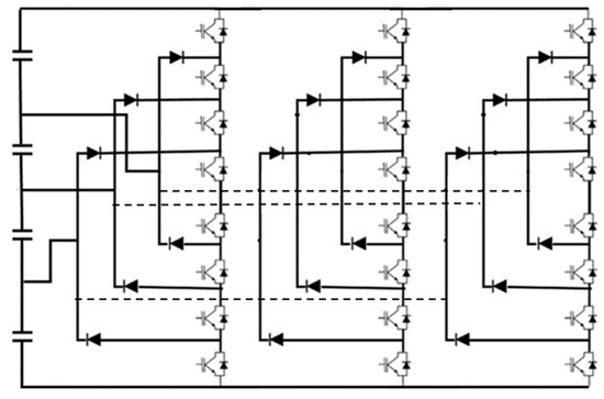
Figure 1.
Five-level diode clamped voltage source inverter.
The function interprets the open or closed state of each switch such as [22]:
In reference to the neutral point (n) of the DC bus voltage, the voltages of the output phases are [22]:
Each inverter branch can have five different switching states: E/2, E/4, 0, −E/2, and −E/2, respectively. Figure 2 shows the spatial voltage vectors of a five-level inverter for all switching states. The output space vector is determined by the combination of the three branches’ switching states. The output terminals a, b, and c of the 401 transistor, for example, have potentials of E/2, 0, and E/4, respectively. The three-level inverter contains 53 = 125 switching states, as indicated in the diagram, since each branch has five types of switching states. Because certain switching states are redundant and form the same space vector, the output voltage vector can only take 61 distinct locations in the figure [24].
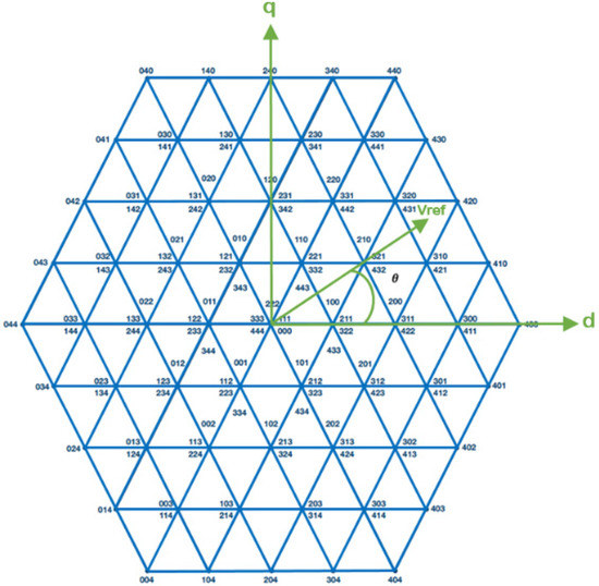
Figure 2.
Space vector diagram of five-level inverter.
4. Principles of Vector and Direct Torque Control
4.1. Vector Control
Mathematically, the command consists in establishing all the transformations to go from a system with a structural double non-linearity to a linear system that ensures the independence between the creation of the flow and the production of the couple as in a separate excitation DC machine [24]. The vector control (VC) technique applied to the induction motor is to adjust the flow by one current component and the torque by the other component. To do this, you must choose an axis system (d, q). Figure 3 shows the VC scheme:
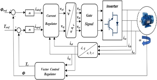
Figure 3.
Vector control scheme.
The application of the VC allows one to obtain:
Under these conditions, we have:
When implementing the decoupling method, the tension equations become:
where:
4.2. Direct Torque Control
The principle of direct torque control (DTC) consists in maintaining the statoric flow in a range. The synoptic scheme of the DTC command is shown in Figure 4 [25,26]. The DTC control of an induction motor is based on the direct determination of the sequence of controls applied to the voltage inverter switches. This strategy is generally based on the use of hysteresis comparators whose role is to control the amplitudes of the statoric flux and the electromagnetic torque.
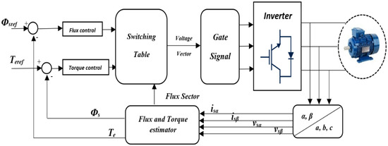
Figure 4.
Direct torque control scheme.
According to the stator and rotor voltage formulas, the stator voltages are obtained:
Therefore, the statoric flux can be calculated by:
where:
The estimated torque and current equations are then obtained:
Substituting (19) in (18) yields:
where the stator flux angle.
The derivative of (20) corresponds to the following result:
To ensure direct control of the stator flux and electromagnetic torque of the inverter-driven induction motor, a switching panel must be developed which best implements the possibilities of the inverter. Table 1 and Table 2 represent, respectively, the switching tables for the two-level and five-level inverters with an NPC structure. They are based on the choice of the statoric voltage vector applied to increase or decrease the statoric flux module and the value of the electromagnetic torque.

Table 1.
Switching table of two-level inverter.

Table 2.
Switching table of five-level inverter.
5. Improved Combined Vector Control and Direct Torque Control Strategy
In this part, a correspondence between the VC and the DTC is presented. It is also proven that the VC and DTC have a common basis despite their differences in implementation [9,10]. Section 4 shows that the rotor flow and electromagnetic torque are approximately the following systems:
where and rely on the parameters of the induction motor.
According to the DTC command, T 5 is broken down into two elements: the first is the radial component which contributes to the control of the level of the statoric flux, and the second element is the tangential component which controls the angle of rotation of the flux [13].
The variation of the electromagnetic torque can then be expressed as [11]:
Using a good approximation:
Substituting (24) into (15) provides:
Thus:
Figure 5 clearly shows that the variation in the amplitude of the statoric flux is:
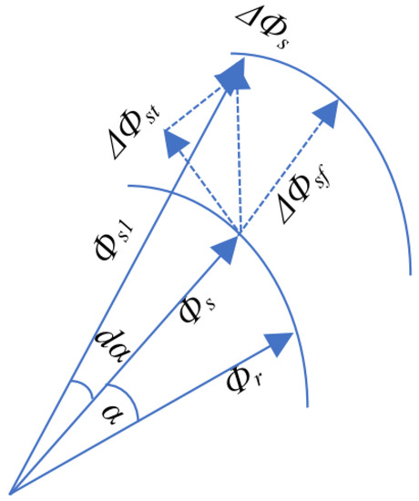
Figure 5.
Flux linkage vector variation.
Equation (24), in relation to (24), gives:
Referring to (22), (26), and (28), the radial component of the DTC flux is proportional to the direct axis component of the statoric current in VC, and the tangential component of the DTC flux is proportional to the quadrature component of the statoric current vector in VC.
Figure 6 shows a block diagram of a combined vector control and direct torque control strategy controlled induction motor drive.
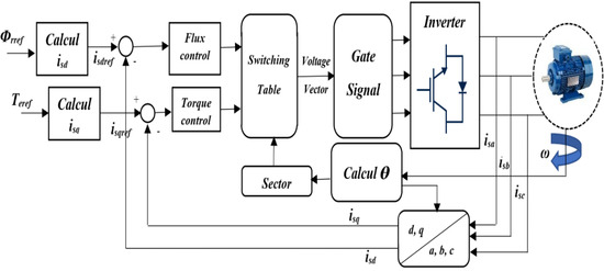
Figure 6.
Combined vector control and direct torque control scheme.
6. Simulation Results
To evaluate the validity and the performance of the system, a numerical simulation model for an induction motor in Figure 6 was developed and modulated under MATLAB/Simulink®. The THD analysis is an effective parameter that must be considered in order to prove the efficiency of the multilevel inverter integration. For this, we studied the harmonic rate of the current Isd and the Isd, the variation between Isdmax and Isdmin and Isqmax and Isqmin.
The results of the currents, voltage waveforms, and THD analysis are discussed in this section. The simulation parameters are those presented in the table in the Appendix A.
6.1. Variable Torque
As shown in Figure 7, Figure 8, Figure 9, Figure 10 and Figure 11, the responses of torque, stator current components, and stator phase current increase from 6 to −6, at t = 2 s.

Figure 7.
Output voltage of the inverter: (a) conventional inverter; (b) five-level inverter.

Figure 8.
Torque response: (a) conventional inverter; (b) five-level inverter.

Figure 9.
Stator current: (a) conventional inverter; (b) five-level inverter.

Figure 10.
Isq components: (a) conventional inverter; (b) five-level inverter.

Figure 11.
Isd components: (a) conventional inverter; (b) five-level inverter.
As the five-level inverter can provide a voltage closer to the sine than the two-level inverter as shown in Figure 7, the torque inverter has been considerably reduced as shown in Figure 8. On the other hand, when using a five-level inverter in a combined VC-DTC structure, it is noted that the distortion of the statoric current and statoric phase current component has been considerably reduced, as shown in Figure 9, Figure 10 and Figure 11. Figure 12 illustrates the FFT analysis of the current Isd and the fundamental harmonic THD, where the THD analysis demonstrates that the THD voltage of the five-level inverter is much lower than the conventional inverter. Table 3 represents theIsd and Isq for the two-level and five-level inverters with an NPC structure. This good low THD result of the five levels and the Isd andIsq demonstrate the efficiency of the multilevel inverter.
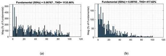
Figure 12.
FFT analysis of the Isd and the fundamental harmonic THD: (a) conventional inverter; (b) five-level inverter.

Table 3.
Isd and Isd of two- and five-level inverters.
6.2. High Speed
To further evaluate the combined VC-DTC proposal, a closed-loop speed control was applied to the drive. The results obtained with the conventional combined VC-DTC are also presented for the sake of comparison. As shown in Figure 13, the speed of the drive increases from 70 to 40 and, finally, drops to 10 rad/s, at t = 4 and 7 s, respectively. Figure 14, Figure 15, Figure 16, Figure 17 and Figure 18 represent the results. Table 4 represents a comparison between theIsd and Isq for the two-level and five-level inverters.

Figure 13.
Speed response: (a) conventional inverter; (b) five-level inverter.

Figure 14.
Torque response: (a) conventional inverter; (b) five-level inverter.

Figure 15.
Stator current: (a) conventional inverter; (b) five-level inverter.

Figure 16.
Isq components: (a) conventional inverter; (b) five-level inverter.

Figure 17.
Isd components: (a) conventional inverter; (b) five-level inverter.

Figure 18.
FFT analysis of the Isd and the fundamental harmonic THD: (a) conventional inverter; (b) five-level inverter.

Table 4.
Isd and Isd of two- and five-level inverters.
6.3. Reverse Speed
As shown in the Figure 19, Figure 20, Figure 21, Figure 22, Figure 23 and Figure 24 and Table 5, the five-level inverter offers high performance compared to the conventional inverter which applies to minimizing the ripple of the stator torque and current. Reverse speed always remains a critical point in the majority of applications; thus, to verify the efficiency of the proposed drive, the induction motor was submitted to a negative reference speed to demonstrate the good results obtained in this case.

Figure 19.
Speed response: (a) conventional inverter; (b) five-level inverter.

Figure 20.
Torque response: (a) conventional inverter; (b) five-level inverter.

Figure 21.
Stator current: (a) conventional inverter; (b) five-level inverter.

Figure 22.
Isq components: (a) conventional inverter; (b) five-level inverter.

Figure 23.
Isd components: (a) conventional inverter; (b) five-level inverter.

Figure 24.
FFT analysis of the Isd and the fundamental harmonic THD: (a) conventional inverter; (b) five-level inverter.

Table 5.
Isd and Isd of two- and five-level inverters.
7. Conclusions
The article presents induction motor control using conventional combined vector control and direct torque control. However, this command causes disadvantages such as a great wealth of harmonic components of the statoric current and the torque. In order to improve the performance of the induction motor, a five-stage inverter to reduce torque ripple was introduced in this system. This article analyzes and compares the operation and efficiency of the control with a five-level inverter compared to the two-level inverter. Tests of simulation of the control by variation of the speed are presented. The results obtained show that the control VC-DTC five levels are very efficient. This demonstrates the effectiveness of the proposed strategy. The experimental data are required to verify the accuracy of the findings from our suggested study. As a further step, we will conduct experiments to compare the outcomes we obtained.
Author Contributions
This paper was developed by a research team from LISA Laboratory. Conceptualization, methodology, and software, O.E.; formal analysis, investigation, and resources, O.E., A.O. and L.E.B.; data curation, O.E. and Z.E.I.; writing—original draft preparation, O.E.; writng—review and editing, O.E.; visualization, O.E., A.O., L.E.B. and Z.E.I.; supervision, A.O. and L.E.B. All authors have read and agreed to the published version of the manuscript.
Funding
This research received no external funding.
Conflicts of Interest
The authors declare no conflict of interest.
Appendix A
Induction motor data: rated power p = 1 kw, rated speed n = 1425 rpm, rated voltage V = 220 V, stator resistance Rs = 6.8 Ω, rotor resistance Rr = 5.43 Ω, stator inductance Ls = 0.3973 H, rotor inductance Ls = 0.3558 H, mutual inductance Lm = 0.3558 H, moment of inertia J = 0.02 Kg·m2, and number of pole pairs p = 2.
References
- Ye, X.; Yang, Z.; Zhu, J.; Guo, Y. Modeling and Operation of a Bearingless Fixed-Pole Rotor Induction Motor. IEEE Trans. Appl. Supercond. 2019, 29, 1–4. [Google Scholar] [CrossRef]
- Aliaskari, A.; Zarei, B.; Davari, S.A.; Wang, F.; Kennel, R.M. A Modified Closed-Loop Voltage Model Observer Based on Adaptive Direct Flux Magnitude Estimation in Sensorless Predictive Direct Voltage Control of an Induction Motor. IEEE Trans. Power Electron. 2020, 35, 630–639. [Google Scholar] [CrossRef]
- Abbasi, M.A.; Husain, A.R.; Idris, N.R.N.; Anjum, W.; Bassi, H.; Rawa, M.J.H. Predictive Flux Control for Induction Motor Drives With Modified Disturbance Observer for Improved Transient Response. IEEE Access 2020, 8, 112484–112495. [Google Scholar] [CrossRef]
- Pacheco, N.O.; Pacheco, J.O.; de Souza, A.B. Vector Control Brushless AC—An approach using power voltage. IEEE Lat. Am. Trans. 2016, 14, 4013–4020. [Google Scholar] [CrossRef]
- Alsofyani, I.M.; Lee, K.B. Enhanced Performance of Constant Frequency Torque Controller–Based Direct Torque Control of Induction Machines with Increased Torque-Loop Bandwidth. IEEE Trans. Ind. Electron. 2020, 67, 10168–10179. [Google Scholar] [CrossRef]
- Manohar, M.; Das, S. Direct torque controlled induction motor drive using modified five-level torque controller for reduction in torque ripple. IET Power Electron. 2020, 13, 1885–1892. [Google Scholar] [CrossRef]
- Halleh, H.; Rahmani, M.; Kimiaghalam, B. Direct Torque Control of induction motors with fuzzy logic controller. In Proceedings of the 2008 International Conference on Control, Automation and Systems, Seoul, Korea, 14–17 October 2008; pp. 345–350. [Google Scholar] [CrossRef]
- Reddy, S.R.P.; Loganathan, U. Robust and High-Dynamic-Performance Control of Induction Motor Drive Using Transient Vector Estimator. IEEE Trans. Ind. Electron. 2019, 66, 7529–7538. [Google Scholar] [CrossRef]
- Boulghasoul, Z.; Elbacha, A.; Elwarraki, E.; Yousfi, D. Combined Vector Control and Direct Torque Control an experimental review and evaluation. In Proceedings of the 2011 International Conference on Multimedia Computing and Systems, Ouarzazate, Morocco, 7–9 April 2011; pp. 1–6. [Google Scholar] [CrossRef]
- Vaez-Zadeh, S.; Jalali, E. Combined vector control and direct torque control method for high performance induction motor drives. Energy Convers. Manag. 2007, 48, 3095–3101. [Google Scholar] [CrossRef]
- Vaez-Zadeh, S.; Jalali, E. An Induction Motor Drive System Employing Salient Features of Vector and Direct Torque Controls. In Proceedings of the 2007 IEEE International Electric Machines & Drives Conference, Antalya, Turkey, 3–5 May 2007; pp. 1264–1268. [Google Scholar] [CrossRef]
- Farasat, M.; Rostami, N.; Feyzi, M.R. Speed sensorless hybrid field oriented and direct torque control of induction motor drive for wide speed range applications. In Proceedings of the 2010 1st Power Electronic & Drive Systems & Technologies Conference (PEDSTC), Tehran, Iran, 17–18 February 2010; pp. 243–248. [Google Scholar] [CrossRef]
- Boulghasoul, Z.; Elbacha, A.; Elwarraki, E. Intelligent Control for Torque Ripple Minimization in Combined Vector and Direct Controls for High Performance of IM Drive. J. Electr. Eng. Technol. 2012, 7, 546–557. [Google Scholar] [CrossRef][Green Version]
- Durgasukumar, G.; Pathak, M.K. THD reduction in performance of multi-level inverter fed induction motor drive. In Proceedings of the India International Conference on Power Electronics 2010 (IICPE2010), New Delhi, India, 28–30 January 2011; pp. 1–6. [Google Scholar] [CrossRef]
- Das, M.K.; Jana, K.C.; Sinha, A. Performance evaluation of an asymmetrical reduced switched multi-level inverter for a grid-connected PV system. IET Renew. Power Gener. 2018, 12, 252–263. [Google Scholar] [CrossRef]
- Wang, T.; Zhang, J.; Wang, H.; Wang, Y.; Diallo, D.; Benbouzid, M. Multi-mode fault-tolerant control strategy for cascaded H-bridge multilevel inverters. IET Power Electron. 2020, 13, 3119–3126. [Google Scholar] [CrossRef]
- Li, C.; Wang, S.; Guan, Q.; Xu, D. Hybrid Modulation Concept for Five-Level Active-Neutral-Point-Clamped Converter. IEEE Trans. Power Electron. 2017, 32, 8958–8962. [Google Scholar] [CrossRef]
- Kim, S.; Kim, R.; Kim, S. Generalized Model Predictive Control Method for Single-Phase N-Level Flying Capacitor Multilevel Rectifiers for Solid State Transformer. IEEE Trans. Ind. Appl. 2019, 55, 7505–7514. [Google Scholar] [CrossRef]
- Oumaymah, E.; Abdellah, O.; Lhoussain, E. The injection of wind power into a grid using a multi-level inverter controlled by SVPWM. In Proceedings of the 2020 International Conference on Electrical and Information Technologies (ICEIT), Rabat-Salé, Morocco, 4–7 March 2020; pp. 1–6. [Google Scholar] [CrossRef]
- Li, N.; Li, W.; Zhang, H.; Yang, P. Efficiency-optimised modulation technique of three-level NPC inverter. J. Eng. 2019, 2019, 938–942. [Google Scholar] [CrossRef]
- Le, Q.A.; Lee, D.C. Reduction of Common-Mode Voltages for Five-Level Active NPC Inverters by the Space-Vector Modulation Technique. IEEE Trans. Ind. Appl. 2017, 53, 1289–1299. [Google Scholar] [CrossRef]
- Rezki, M.; Griche, I. Simulation and Modeling of a Five -Level (NPC) Inverter Fed by a Photovoltaic Generator and Integrated in a Hybrid Wind-PV Power System. Eng. Technol. Appl. Sci. Res. 2017, 7, 1759–1764. [Google Scholar] [CrossRef]
- Oumaymah, E.; Abdellah, O.; Omar, B.; Lhoussain, E. NPC five level inverter using SVPWM for Grid-Connected Hybrid Wind-Photovoltaic Generation System. Adv. Sci. Technol. Eng. Syst. J. 2020, 5, 7. [Google Scholar] [CrossRef]
- He, H.; Xing, J. Design of Induction Motor Speed-Sensorless Vector Control System. In Proceedings of the 2016 International Symposium on Computer, Consumer and Control (IS3C), Xi’an, China, 4–6 July 2016; pp. 563–566. [Google Scholar] [CrossRef]
- Vinod, B.R.; Baiju, M.R.; Shiny, G. Five-Level Inverter-Fed Space Vector Based Direct Torque Control of Open-End Winding Induction Motor Drive. IEEE Trans. Energy Convers. 2018, 33, 1392–1401. [Google Scholar] [CrossRef]
- Oumaymah, E.; Abdellah, O.; Omar, B.; Lhoussain, E. Backstepping Design Control Applied to the Wind PMSG Generator and Grid Connection Using A Multilevel Inverter. In Proceedings of the 2021 8th International Conference on Electrical and Electronics Engineering (ICEEE), Antalya, Turkey, 9–11 April 2021; pp. 136–141. [Google Scholar] [CrossRef]
Publisher’s Note: MDPI stays neutral with regard to jurisdictional claims in published maps and institutional affiliations. |
© 2022 by the authors. Licensee MDPI, Basel, Switzerland. This article is an open access article distributed under the terms and conditions of the Creative Commons Attribution (CC BY) license (https://creativecommons.org/licenses/by/4.0/).