1. Introduction
Hybrid excitation synchronous machines (HESM) incorporate both permanent magnets and field winding for field excitation [
1]. By employing these two excitation field sources, the flux weakening capability and hence the speed range can be significantly improved [
2]. According to the arrangement of PM and excitation coils, HESM can be represented as series hybrid excitation (SHE) and parallel hybrid excitation (PHE) machines [
3].
For PHE machines, the excitation fluxes produced by PMs and field winding have different trajectories [
4]. Therefore, the risk of irreversible demagnetization of the PMs can be avoided. Among those PHE machines, the consequent-pole PM (CPPM) machine possesses inherent field weakening capability [
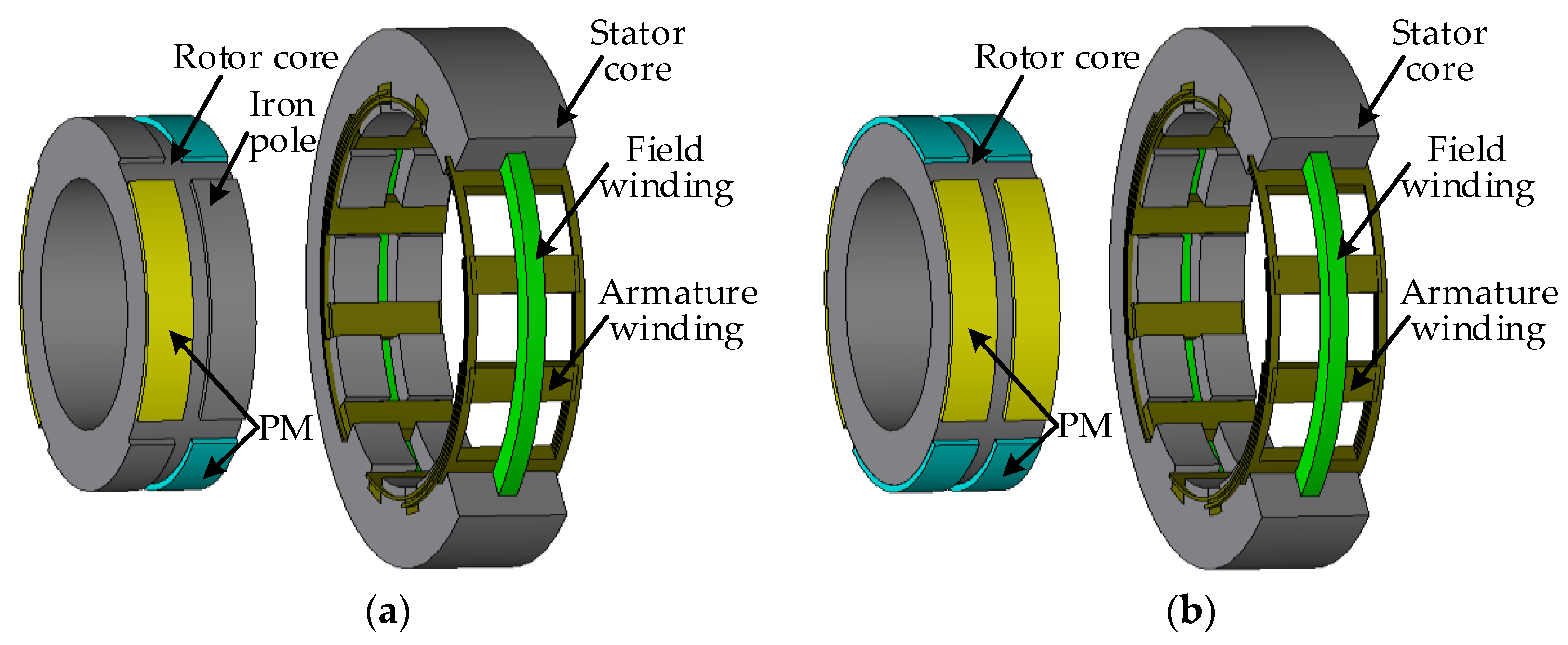
5]. The PM and field-winding are housed in the rotor and stator separately. Therefore, air-gap flux can be regulated, and the demagnetization risk can be avoided. Meanwhile, as the field control winding is housed in the stator, the brushes or slip rings can be eliminated. Besides, compared with traditional PM machine, less rare-earth PM is required, as CPPM machine employed iron-pole to replace half of PM poles [
6], as shown in
Figure 1.
To improve machine’s power density and torque density, various design methods have been proposed in CPPM machines [
7,
8]. For example, in [
9], the fundamental of the air-gap flux density distribution can be improved by optimizing the width of PMs.
In these papers, the finite element method (FEM) is generally employed. Thanks to the enormous improvement in digital computing, FEM has developed into a mature modeling technique, capable of accurately predicting motor performance. Meanwhile, many available FEM software packages, such as JMAG [
4], Ansys [
10] and MotorSolve [
11], have largely simplified the implementation. However, compared to the analytical models, FEM is very time-consuming, especially for three-dimensional (3-D) motors [
12]. Therefore, analytical methods, such as nonlinear varying-network magnetic circuit (NVNMC) method and Fourier modeling method, are proposed for the initial design. Based on analytical equations and often tuned empirically, analytical methods can provide comparatively accurate prediction of the motor performance, and take the definite advantages of fast computation and simple implementation [
13]. Based on previous research results, a comparison between FEM, Fourier modeling method and NVNMC is listed in
Table 1. It can be seen that NVNMC model is more suitable for saturation condition than Fourier modeling method [
13]; thus, the former one is employed in this paper. However, the available NVNMC model is ill-suited for advanced machines with 3-D flux flow.
The purpose of this paper is to develop the NVNMC model of CPPM machines, hence assessing their electromagnetic performances, including the magnetic field distribution and back-electromotive force (EMF). The two-dimensional (2-D) NVNMC for CPPM machines is presented, and magnetic saturation and flux leakage is considered. This paper considers, for the first time, the use of 2-D NVNMC model to predict the performance of 3-D machine. In order to verify the accuracy of the proposed model, the NVNMC results and FEM results are quantitatively compared. Consequently, the proposed NVNMC method can be employed as a tool to optimize the CPPM machine in future study.
In
Section 2, the NVNMC model of CPPM machine in [
14] will be described. Then, the model is analyzed in
Section 3.
Section 4 will be devoted to solving this model. Then, the results will be presented in
Section 5, and these are compared with FEM results. Finally, a conclusion will be drawn in
Section 6.
2. NVNMC Model
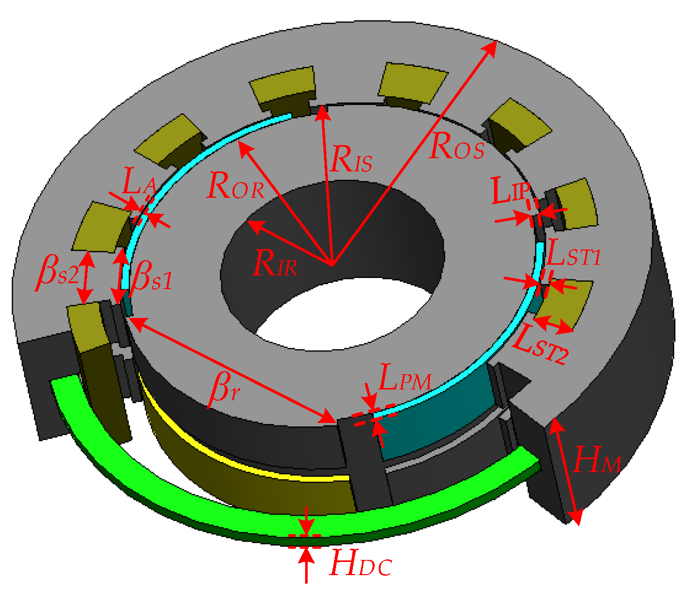
Figure 1a shows the structure of a three-phase 12-slot 4-pole CPPM machine. It should be mentioned that the rotor has radially magnetized bipolar PMs distributed alternatively in the circumferential direction, and other parts are iron poles (also called rotor tooth in this paper) [
6]. Due to symmetry, this CPPM machine can be considered as two 6/2-pole machines. Hence, the modeling is needed only for the 6/2-pole machine.
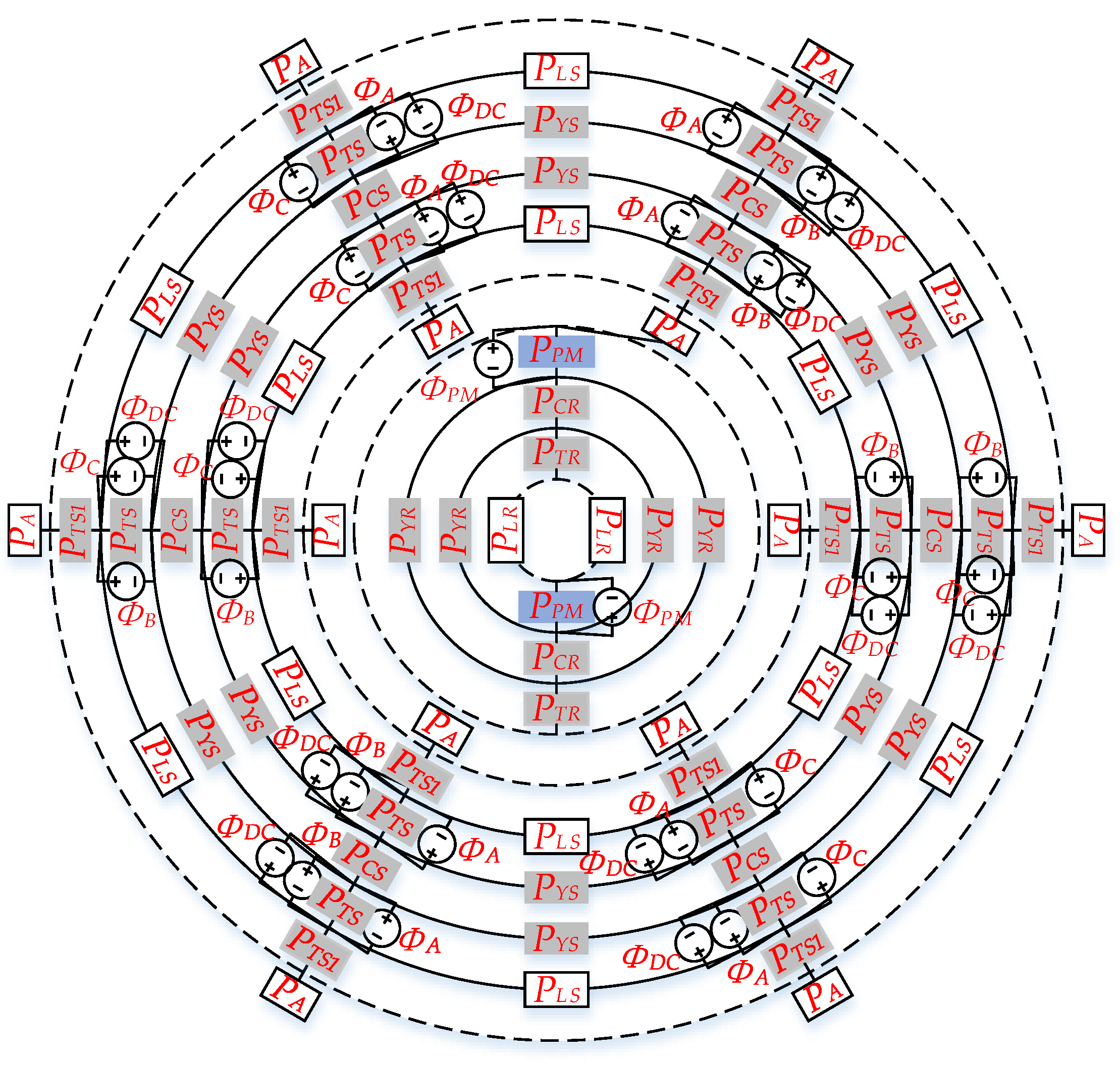
Although the machine involves 3-D flux flow, the corresponding 2-D NVNMC model is depicted in
Figure 2. The key is to translate the 3-D flux path into a 2-D NVNMC model properly, namely the upper half of rotor is drawn inside the rotor yoke, while the upper half of stator is drawn outside the stator yoke.
In this model,
PTR,
PYR,
PCR,
PTS1,
PTS,
PYS, and
PCS are the permeances of rotor tooth, rotor yoke, rotor consequent-yoke, stator inner tooth, stator outer tooth, stator yoke, and stator consequent-yoke, respectively, which vary with the nonlinear saturation in the corresponding magnetic paths, while
PPM,
PLR, and
PLS are the permeances of PM, rotor tooth-to-PM leakage flux, and stator tooth-to-tooth leakage flux, respectively, which are of constant permeability [
18].
It should be emphasized that although there is only one PA module drawn in front of each stator tooth in the model, it can be considered as each stator tooth having two PA modules connecting the PM and rotor tooth. So, there is a total of 24 PA modules in this model, and apparently, the value of some PA modules could become zero when the rotor is rotating. Besides, the connection lines between the outer PA and inner PM, as well as rotor teeth, are omitted in this figure.
In addition, ΦPM, ΦA, ΦB, ΦC and ΦDC represent the magnetic flux source (MFS) of the PM, phase A winding, phase B winding, phase C winding and field winding, respectively. It should be noted that the armature MFS supplied by phase A, phase B, and phase C winding is represented by eight ΦA, ΦB, and ΦC modules separately, while the MFS provided by DC winding is represented by twelve ΦDC modules.
3. Model Analysis
In NVNMC model, the magnetic field distribution is highly related to the geometry of the PM and the reluctance of its path. In this case, the magnetic flux source, the air-gap, and magnet reluctances are the most important values.
The basic equation which governs the permeance of each element is given by [
21]
where
μ0 and
μiron are the permeability of air and iron region, while
b,
h, and
l are the width, height, and length of the element.
Although most elements’ permeances can be easily acquired from (1), the calculations of main air-gap, stator and rotor cores are difficult and subtle. Hence, the calculation procedure for these parts is detailed in the following.
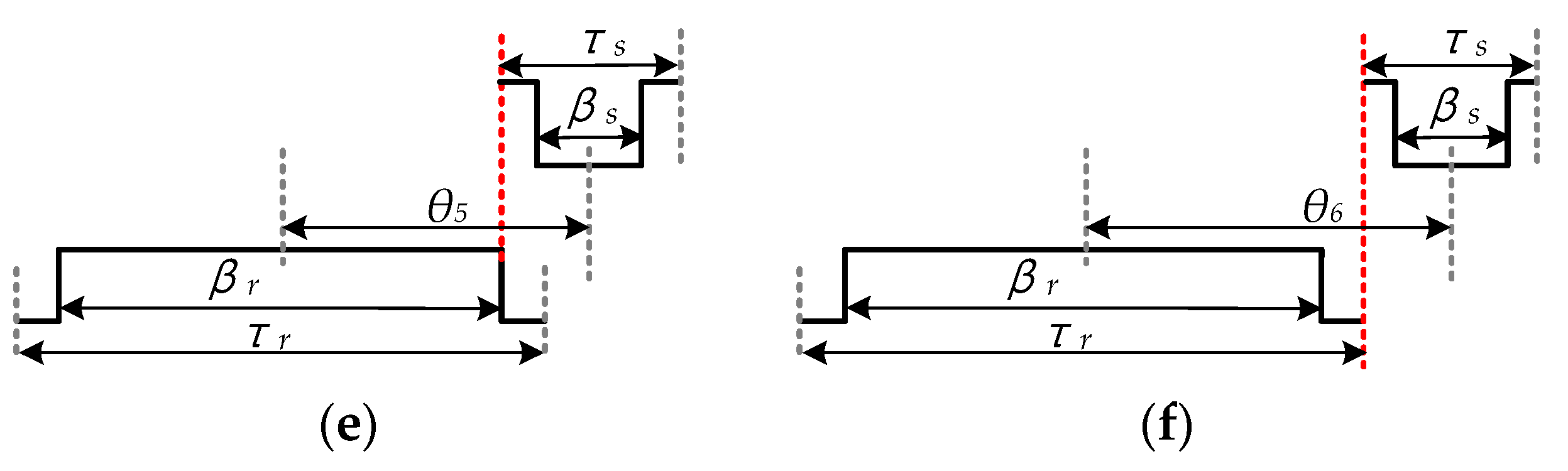
3.1. The Permeance of Air-Gap
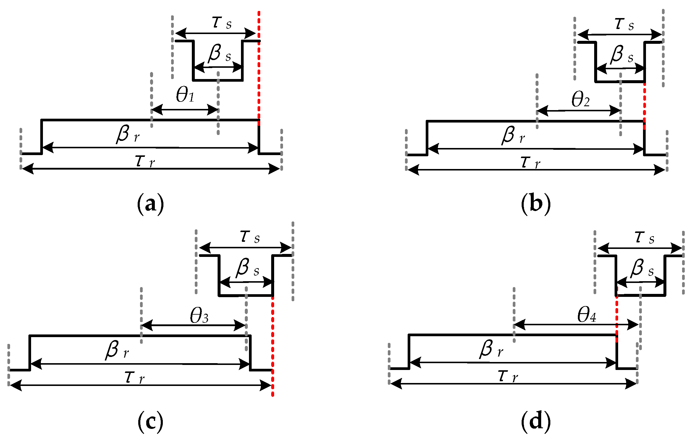
As the permeance of air-gap is varying with the rotor position, the whole mechanical period is separated into seven regions, which can be defined as Region 1 0 ≤
θ ≤
θ1, Region 2
θ1 <
θ ≤
θ2, …, and Region 7
θ6 <
θ, where
θ is the angle between the central lines of rotor and stator teeth. As depicted in
Figure 3,
θ1 to
θ6 can be calculated as
θ1 = 1/2 × (
βr −
τs),
θ2 = 1/2 × (
βr −
βs),
θ3 = 1/2 × (
τr −
βs),
θ4 = 1/2 × (
βr +
βs),
θ5 = 1/2 × (
βr +
τs), and
θ6 = 1/2 × (
τr +
τs), where
τr and
τs are the pole pitches of rotor and stator, and
βr and
βs are the tooth arc of rotor and stator.
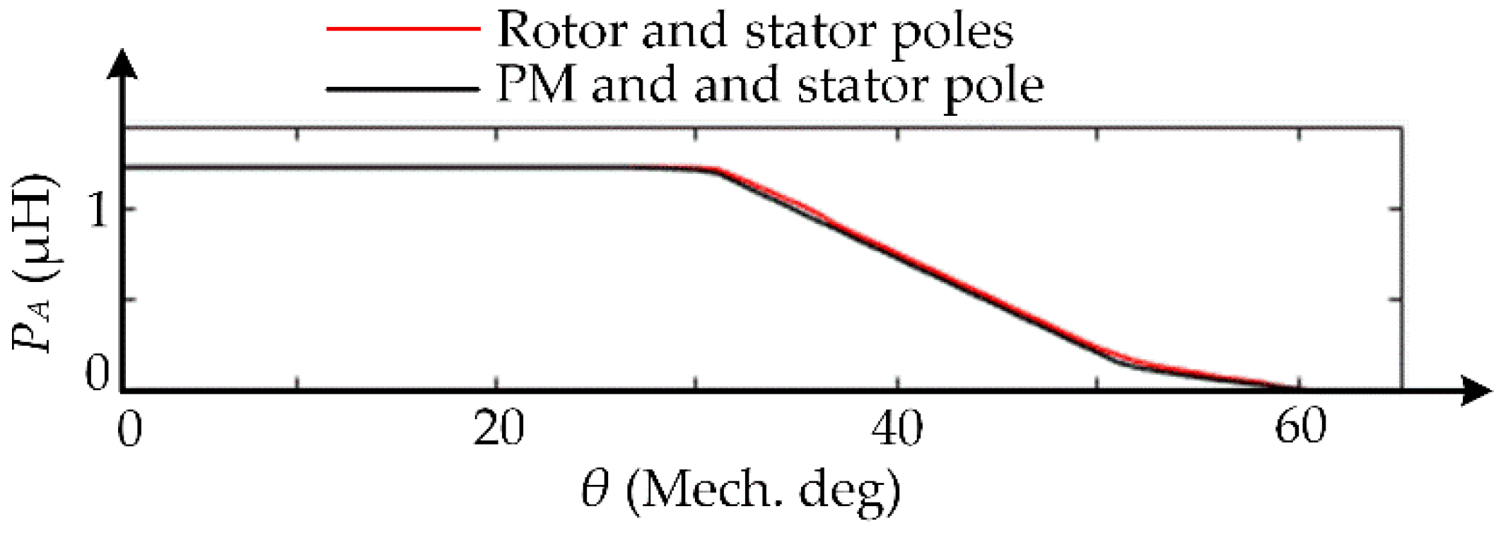
By employing the calculation method in [
18], the air-gap permeance in each region can be calculated. It should be noted that the permanence between rotor yoke and stator pole should not be considered when calculating the
PA between PM and stator pole. In this paper,
PA-
θ curve, the relationship between air-gap permeance and rotor angle, is shown in
Figure 4.
3.2. The Permeance of Tooth, Yoke, and Consequent-Yoke
Figure 5a,b show the field distribution of the stator and rotor core separately. In order to analyze these two iron regions, the stator is separated as stator tooth (including
PTS1 and
PTS), stator yoke, and stator consequent-yoke, so that the corresponding magnetic field distributions can be seen as radial, circumferential, and axial directions, respectively [
22]. Similarly, the magnetic field distributions in the rotor tooth, rotor yoke, and rotor consequent-yoke are separated in accordance with the relevant parts of the stator.
To separate the stator and rotor core preciously, the widths of
PCR and
PCS, as well as the lengths of
PYR and
PYS, are specified based on FEM [
18], and change dynamically with field current. But it should be mentioned that the FEM simulation only needs to run a few angles to get the widths of
PCR and
PCS, thus the time can be saved. Then, as the magnetic field distribution in each element is simplified as one-directional [
23], (1) can be employed to calculate the
PTR,
PYR,
PCR,
PTS1,
PTS,
PYS, and
PCS.
3.3. The Magnetic Flux Source
The magnetomotive force (MMF) obtained from PM can be simplified as [
24]
where
hm and
Br is the thickness and the remanence of PM, separately.
Therefore, the MFS of PM, namely
ΦPM, can be acquired by
where
PPM is the permeance of PM, which can be obtained through (1).
The armature windings are formed by symmetrical three-phase windings. Taking phase C winding as an example, the MMF can be acquired through [
25]
where
NC and
IC are the number of turns and the current of phase C winding, respectively.
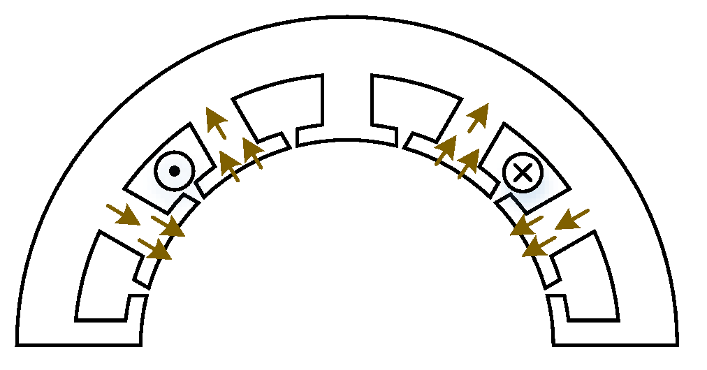
It should be noticed that as the armature field flows as
Figure 6 shows, the whole MMF is evenly distributed to every stator tooth near the armature windings.
For the field-winding, it is formed by DC coils. The MMF of this winding can be acquired through [
25]
where
NDC and
IDC are the numbers of turns and the current of DC windings, separately.
It should be emphasized that the flux excited by DC winding flows from one stator tooth to another axially adjacent tooth through the stator consequent-yoke. Therefore, the whole MMF is evenly distributed to every stator tooth.
The basic equation which governs the MFS of each stator tooth is given by [
25]
4. Magnetic Circuit Equations
4.1. Establishment of the Magnetic Circuit Equations
The nodal analysis and Kirchhoff’s Law are employed to establish the magnetic circuit, the basic equation which governs the whole NVNMC model is given by [
24]
where
n number of nodes;
P(i, j) for i, j = 1, 2, …, n − 1, is the permeance of branch, which connects node i and j;
F(i) for i = 1, 2, …, n − 1, is the node magnetic potential;
Φs(i) for i = 1, 2, …, n − 1, is the node magnetic flux source.
It should be mentioned that the number of independent nodes in this model is n − 1, and the magnetic potential for node n is zero.
4.2. Calculation of the Magnetic Circuit Equations
As the magnetic circuit equation is established in the former section, the magnetic potential of all nodes can be obtained by [
26]
where
P,
F, and
Φs are the node permeance matrix, node magnetic vector potential, and node magnetic flux source, respectively.
Then the magnetic flux in each branch can be deduced by [
18]
where
Φ(
i, j) is the magnetic flux flows branch, which connects nodes
i and
j.
However, it should be noticed that the permeance of each branch is varying; i.e., the permeance of the main air-gap varies as the rotor rotates, and the permeance of stator and rotor element varies as the flux density changes. Different from air-gap permeance, which can be acquired by employing an appropriate
PA −
θ curve (depicted in
Figure 4), the precise permeance of the iron region can only be obtained by solving the NVNMC model iteratively [
17]. In detail, by employing a reliable initial value of iron permeability, such as 3500
μ0, the magnetic flux in each iron element can be acquired through (10), as well as the magnetic flux density can be obtained. Therefore, the permeability of this region can be updated through the material’s
B-
H curve.
Nevertheless, directly employing the new permeability in (8) is ill-suitable, because the iteration procedure could be an endless loop in this case. For example, if the flux density acquired in (
k − 1)th step is higher than 2T, then the permeability
μk−1iron would be relatively small, such as 100
μ0, then with this value, the flux density acquired in
kth step could be much lower, such as 1T, and the corresponding permeability, namely
μkiron, could be 4000
μ0, so the flux density acquired in (
k + 1)th step could be 2T again. Hence, to avoid this problem, the permeability for
kth iteration can be obtained by [
24]
where
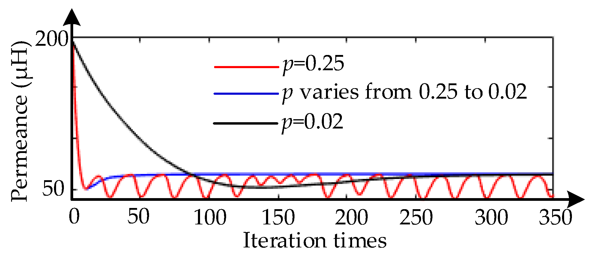
p is a damping factor that is between 0 to 1, and is varying with the iteration steps. For example, damping factor could be 0.3, 0.1 and 0.02 in the first, second and last ten iterations. Compared with fixed damping factor, the precise result can be acquired quickly with varying damping factor. Taking the stator tooth as an example, the permeance of stator tooth is shown in
Figure 7. It can be observed that this model cannot acquire precise result when damping factor is 0.25, and it takes a long time to solve the NVNMC model when damping factor is 0.02. However, the precise result can be acquired quickly with varying damping factor.
When the discrepancy between
μk−1iron and
μkiron is tolerable, the iteration can be finished, and the precise solution of this NVNMC model can be acquired [
23].
5. Results and Discussion
Based on the aforementioned solving procedure, major parameters of the CPPM machine are determined as listed in
Table 2, and marked in
Figure 8, which will be used for predicting electromagnetic performance. It should be noted that the method of determining winding turns is given in [
11]. Besides, the results acquired by NVNMC models and 3-D FEM are compared in this section.
5.1. Coil Flux Linkage
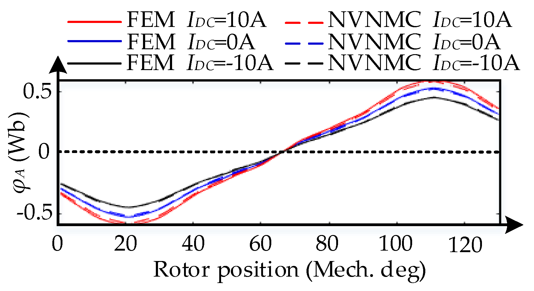
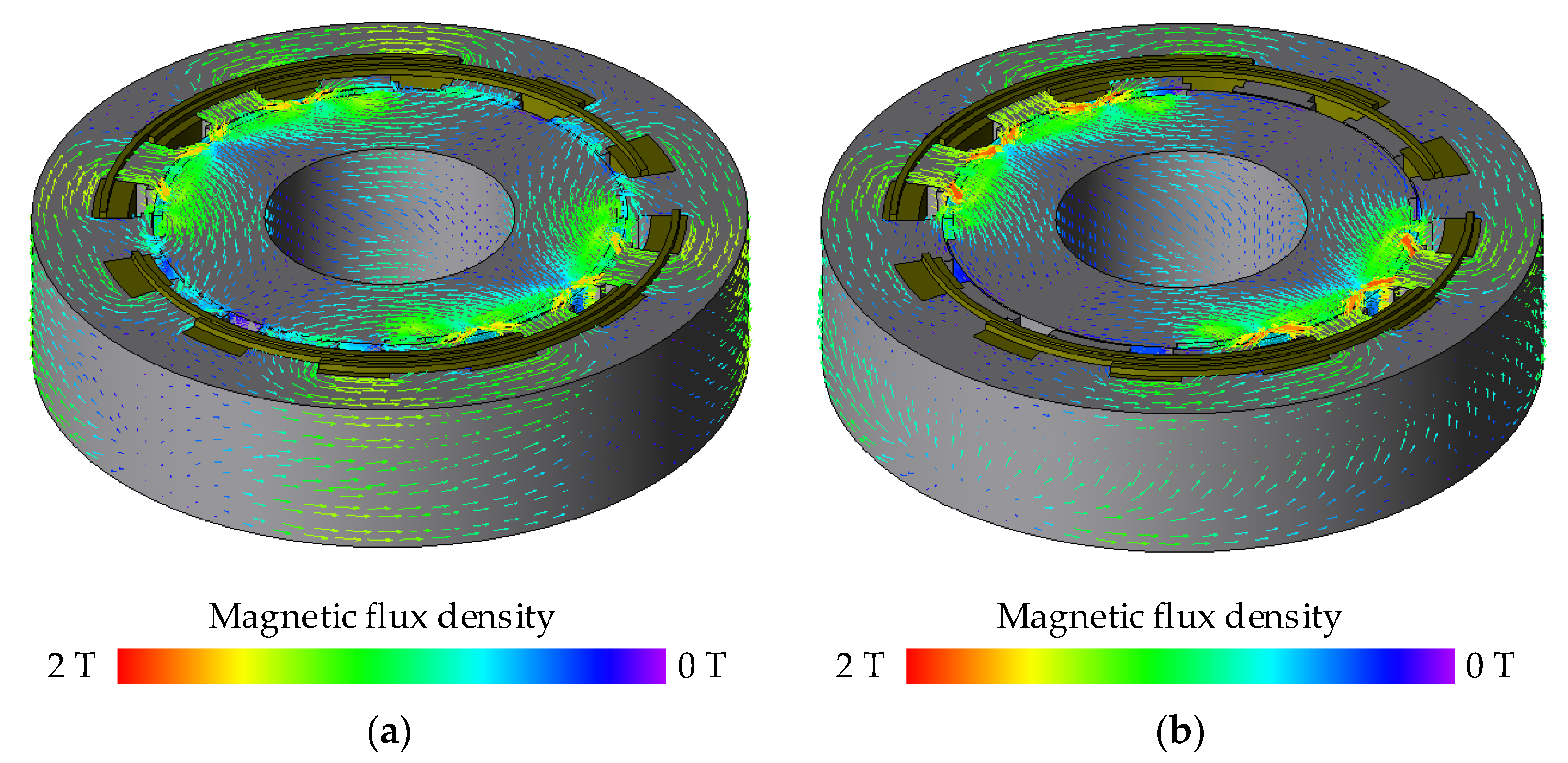
Figure 9 shows the waveforms of
φA, namely the coil flux linkage of phase A. Meanwhile, the strengthening and weakening actions of the armature current are tested under different field winding currents with the value of 0 A, 10 A and −10 A. As aforementioned, hybrid excitation machines can regulate the field flux by varying the current of field winding, as shown in
Figure 10. It can be seen that more flux flows at circumferential direction with 10 A field winding current, thus the width of
PCR and
PCS should be smaller; however, when the system is weakening the field flux, more flux flows at axial direction; thus, the width of
PCR and
PCS should be larger. But it should be mentioned that the width of
PCR and
PCS are not linearly related to the field current because of the saturation. Therefore, based on FEM, the widths of
PCR and
PCS are set as 40%, 25% and 55% of the stator and rotor pitches, when the field current is 0 A, 10 A and −10 A, respectively. As can be seen in
Figure 9, a good agreement can be obtained between NVNMC and 3-D FEM.
5.2. Back-EMF
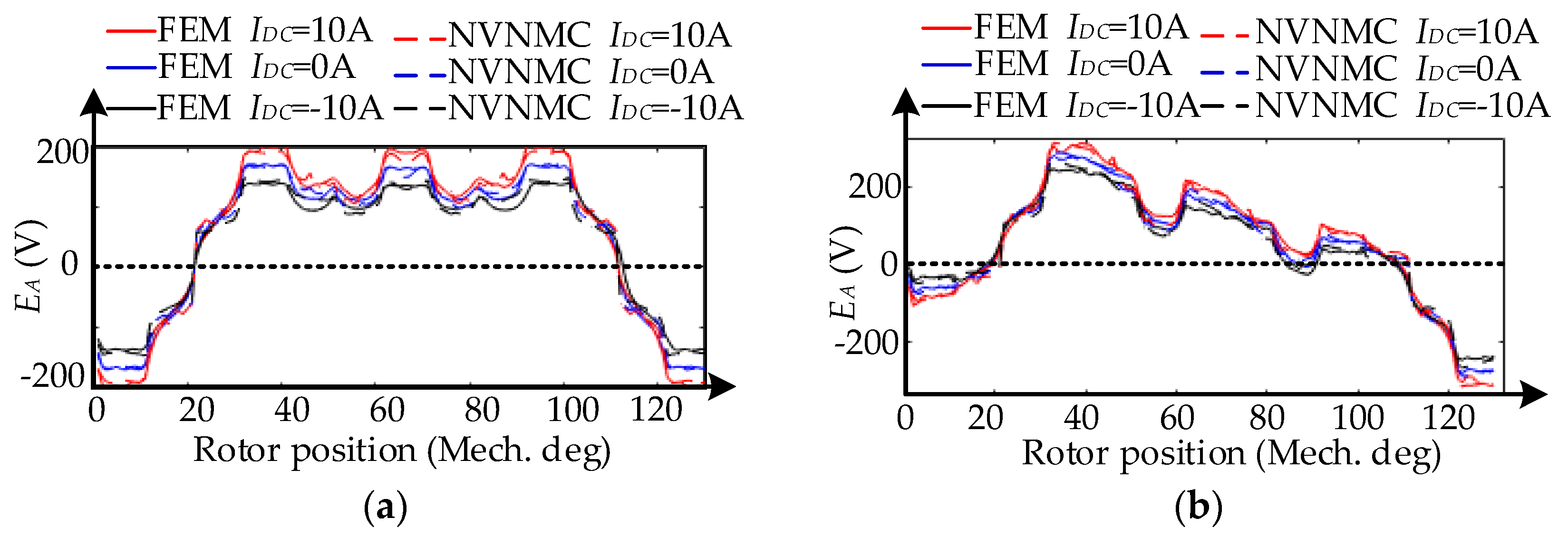
Figure 11 illustrates
EA, the back-EMF of phase A, versus rotor angle under different
IDC and phase current, which can be acquired through [
14]
where
ω is the angular velocity of the rotor.
As can be seen, there are few discrepancies between back-EMF calculated by the NVNMC model and FEM. Because the NVNMC method employs the simplified 2-D model to replace the 3-D machine, and the aim of this method is to rapidly predict the dynamic performance of CPPM machines with different dimensions and excitation conditions. Therefore, the degradation of accuracy is tolerable in view of the time-saving.
However, it should be mentioned that, as shown in
Figure 11a, the results of NVNMC are not so accurate in some regions. The main reason is that the air-gap magnetic field is very complicated, especially in region 5 and region 6 (
θ5 <
θ), thus when the rotor turns around 30 and 110 degrees, the results of these two methods are different.
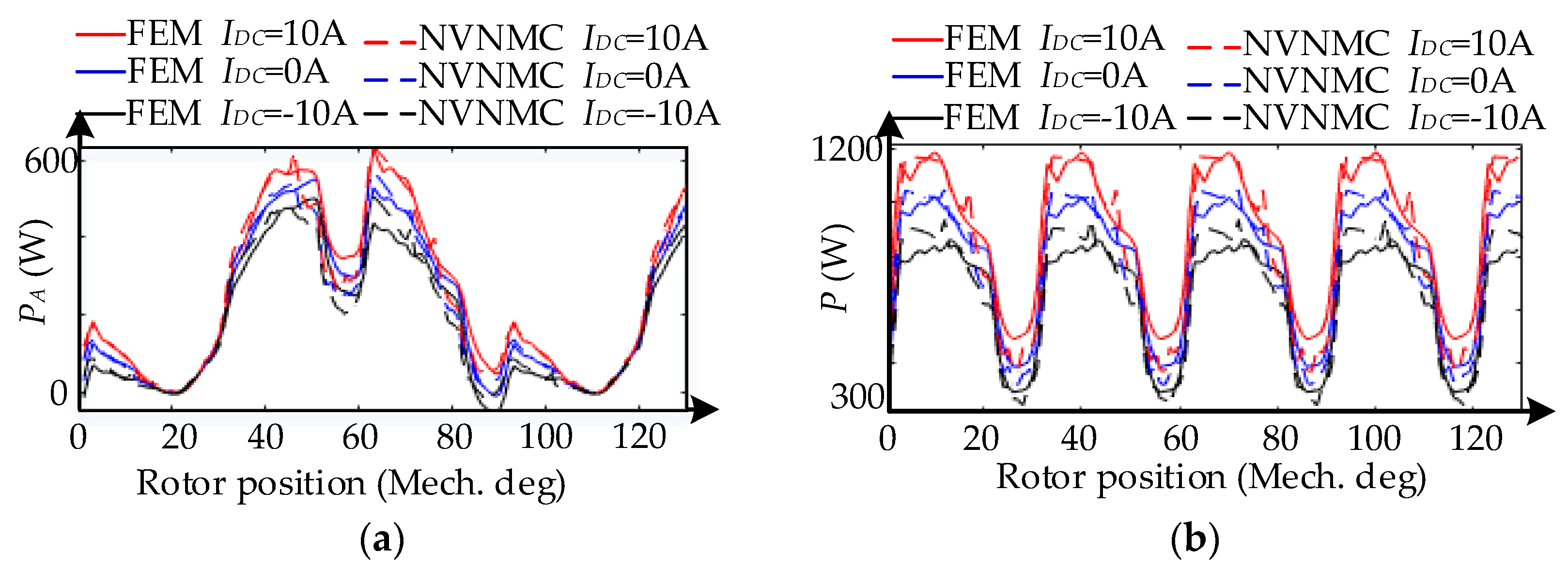
5.3. Power
As the winding internal resistance is very small, the copper loss is not considered in this paper. Thus, the input power of phase A and total input power be simplified as [
27]
and
Figure 12 shows the variation of the input power with rotor position, fed by three-phase AC current with the peak of 3 A. As will be seen, the results acquired from NVNMC model compare well with those from 3-D FEM.
5.4. Discussion
Consistent with the theoretical analysis, the proposed NVNMC method can provide comparatively reliable results in a shorter time. As a matter of fact, the NVNMC software Matlab only needs to run 2 min, while the FEM software JMAG needs to run 27 h for one cycle with same computer. Besides, it is easy to see which part is too saturated and limits the flow of machine’s magnetic field; thus, we can optimize the motor parameters with physical insight.
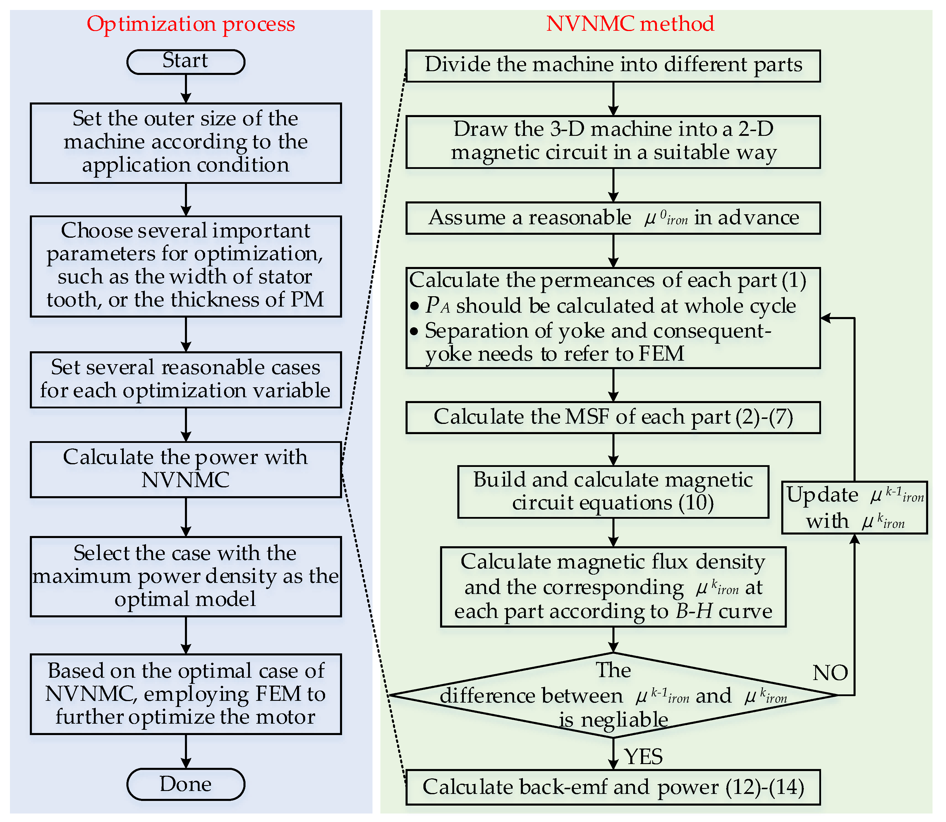
However, the result of NVNMC method is still not as accurate as FEM method. The main reason is that the NVNMC method separates the machine into dozens of elements, and assuming the magnetic field is evenly distributed in each element to calculate the permeability. However, uneven distribution of magnetic field is unavoidable, thus it is inappropriate to calculate the permeance of each element with single permeability. In theory, this problem can be solved by separating the machine into smaller elements, as FEM method separates the machine into numerous meshes, but the running time is inevitably increased. Therefore, it is better to use NVNMC method for initial design and refine the design with FEM method, as shown in
Figure 13. Considering there are too many parameters that can have an impact on the performance of the motor, how to optimize these parameters quickly and reasonably will become the future research direction of this study.
6. Conclusions
In this paper, a 2-D NVNMC modeling approach has been developed to predict the electromagnetic performance, namely the air-gap field distribution and the back-EMF. The detailed calculation procedure for the permeance of main air-gap, stator, and rotor is introduced. The dynamic segmentation method is proposed, making the calculated static characteristics agree more closely with those found by FEM. Besides, the saturation is also considered, making the calculated static characteristics agree more closely with those found by FEM, and the comparisons also show that the proposed NVNMC approach offers reasonable accuracy. Furtherly, this modeling method can also be applied to other 3-D machines.
Author Contributions
The work presented in this paper is the output of the research projects undertaken by H.W. In particular, H.W. developed the topic, analyzed the results, and wrote the paper. K.T.C., C.H.T.L., C.C.C. and T.Y. helped provide guidance and resources for improving the paper. All authors have read and agreed to the published version of the manuscript.
Funding
This research was funded by a grant (Project No. 17205518) from the Hong Kong Research Grants Council, Hong Kong Special Administrative Region, China.
Institutional Review Board Statement
Not applicable.
Informed Consent Statement
Not applicable.
Data Availability Statement
Not applicable.
Conflicts of Interest
The authors declare no conflict of interest.
References
- Cao, L.; Chau, K.T.; Lee, C.H.T. A new parallel-hybrid-excited permanent-magnet machine with harmonic-differential effect for electric vehicles. IEEE Trans. Veh. Technol. 2020, 69, 12734–12750. [Google Scholar] [CrossRef]
- Chau, K.T.; Jiang, C.; Han, W.; Lee, C.H.T. State-of-the-art electromagnetics research in electric and hybrid vehicles. Prog. Electromagn. Res. 2017, 159, 139–157. [Google Scholar] [CrossRef] [Green Version]
- Sun, L.; Zhang, Z.; Gu, X.; Yu, L.; Li, J. Analysis of reactive power compensation effect of a new hybrid excitation brushless dc generator. IEEE Trans. Ind. Electron. 2020, 67, 3562–3572. [Google Scholar] [CrossRef]
- Cao, L.; Chau, K.T.; Lee, C.H.T.; Lam, W.-H. Design and analysis of a new parallel-hybrid-excited machine with harmonic-shift structure. IEEE Trans. Ind. Electron. 2020, 67, 1759–1770. [Google Scholar] [CrossRef]
- Zhao, H.; Liu, C.; Song, Z.; Liu, S. A consequent-pole pm magnetic-geared double-rotor machine with flux-weakening ability for hybrid electric vehicle application. IEEE Trans. Magn. 2019, 55, 1–7. [Google Scholar] [CrossRef]
- Sakamoto, S.; Yokoi, Y.; Higuchi, T.; Miyamoto, Y. A study on rotor design of consequent-pole permanent magnet machines. In Proceedings of the 23rd International Conference on Electrical Machines and Systems, Hamamatsu, Japan, 24–27 November 2020. [Google Scholar]
- Li, J.; Wang, K. A novel spoke-type pm machine employing asymmetric modular consequent-pole rotor. IEEE ASME Trans. Mechatron. 2019, 24, 2182–2192. [Google Scholar] [CrossRef]
- Li, J.; Wang, K.; Zhang, H. Flux-focusing permanent magnet machines with modular consequent-pole rotor. IEEE Trans. Ind. Electron. 2020, 67, 3374–3385. [Google Scholar] [CrossRef]
- Li, J.; Wang, K.; Liu, C. Torque improvement and cost reduction of permanent magnet machines with a dovetailed consequent-pole rotor. IEEE Trans. Energy Convers. 2018, 33, 1628–1640. [Google Scholar] [CrossRef]
- Cao, R.; Su, E.; Lu, M. Comparative study of permanent magnet assisted linear switched reluctance motor and linear flux switching permanent magnet motor for railway transportation. IEEE Trans. Appl. Supercond. 2020, 30, 1–5. [Google Scholar] [CrossRef]
- Amitkumar, K.S.; Thike, R.; Pillay, P. Linear amplifier-based power-hardware-in-the-loop emulation of a variable flux machine. IEEE Trans. Ind. Appl. 2019, 55, 4624–4632. [Google Scholar] [CrossRef]
- Sun, W.; Li, Q.; Sun, L.; Zhu, L.; Li, L. Electromagnetic analysis on novel rotor-segmented axial-field srm based on dynamic magnetic equivalent circuit. IEEE Trans. Magn. 2019, 55, 1–5. [Google Scholar] [CrossRef]
- Sprangers, R.L.J.; Paulides, J.J.H.; Gysen, B.L.J.; Lomonova, E.A. Magnetic saturation in semi-analytical harmonic modeling for electric machine analysis. IEEE Trans. Magn. 2016, 52, 1–10. [Google Scholar] [CrossRef]
- Tapia, J.A.; Leonardi, F.; Lipo, T.A. Consequent-pole permanent-magnet machine with extended field-weakening capability. IEEE Trans. Ind. Appl. 2003, 39, 1704–1709. [Google Scholar] [CrossRef] [Green Version]
- Gysen, B.L.J.; Ilhan, E.; Meessen, K.J.; Paulides, J.J.H.; Lomonova, E.A. Modeling of flux switching permanent magnet machines with fourier analysis. IEEE Trans. Magn. 2010, 46, 1499–1502. [Google Scholar] [CrossRef] [Green Version]
- Ping, J.; Shuhua, F.; Ho, S.-L. Distribution characteristic and combined optimization of maximum cogging torque of surface-mounted permanent-magnet machines. IEEE Trans. Magn. 2018, 54, 1–5. [Google Scholar] [CrossRef]
- Bao, J.; Gysen, B.L.J.; Lomonova, E.A. Hybrid analytical modeling of saturated linear and rotary electrical machines: Integration of fourier modeling and magnetic equivalent circuits. IEEE Trans. Magn. 2018, 54, 1–5. [Google Scholar] [CrossRef] [Green Version]
- Cheng, M.; Chau, K.T.; Chan, C.C.; Zhou, E.; Huang, X. Nonlinear varying-network magnetic circuit analysis for doubly salient permanent-magnet motors. IEEE Trans. Magn. 2000, 36, 339–348. [Google Scholar] [CrossRef]
- Zhu, Z.Q.; Pang, Y.; Howe, D.; Iwasaki, S.; Deodhar, R.; Pride, A. Analysis of electromagnetic performance of flux-switching permanent-magnet machines by nonlinear adaptive lumped parameter magnetic circuit model. IEEE Trans. Magn. 2005, 41, 4277–4287. [Google Scholar] [CrossRef]
- Wang, M.; Zheng, P.; Tong, C.; Zhao, Q.; Qiao, G. Research on a transverse-flux brushless double-rotor machine for hybrid electric vehicles. IEEE Trans. Ind. Electron. 2019, 66, 1032–1043. [Google Scholar] [CrossRef]
- Fitzgerald, A.E.; Kingsley, C.; Umans, S.D. Fitzgerald and Kingsley’s Electric Machinery, 7th ed.; McGraw-Hill: New York, NY, USA, 2013. [Google Scholar]
- Li, B.; Li, G.-D.; Li, H.-F. Magnetic field analysis of 3-dof permanent magnetic spherical motor using magnetic equivalent circuit method. IEEE Trans. Magn. 2011, 47, 2127–2133. [Google Scholar] [CrossRef]
- Li, N.; Zhu, J.; Lin, M.; Yang, G.; Kong, Y.; Hao, L. Analysis of axial field flux-switching memory machine based on 3-d magnetic equivalent circuit network considering magnetic hysteresis. IEEE Trans. Magn. 2019, 55, 1–4. [Google Scholar] [CrossRef]
- Fu, D.; Gong, J.; Xu, Y.; Gillon, F.; Bracikowski, N. Coupled circuit and magnetic model for a transverse flux permanent magnet linear motor. IEEE Access 2020, 8, 159274–159283. [Google Scholar] [CrossRef]
- Yu, C.; Niu, S. Development of a magnetless flux switching machine for rooftop wind power generation. IEEE Trans. Energy Convers. 2015, 30, 1703–1711. [Google Scholar] [CrossRef]
- Liu, G.; Ding, L.; Zhao, W.; Chen, Q.; Jiang, S. Nonlinear equivalent magnetic network of a linear permanent magnet vernier machine with end effect consideration. IEEE Trans. Magn. 2018, 54, 1–9. [Google Scholar] [CrossRef]
- Shi, H.; Niguchi, N.; Hirata, K. Design and analysis of surface permanent magnet vernier linear motor based on air gap magnetic flux density distribution. In Proceedings of the 12th International Symposium on Linear Drives for Industry Applications, Neuchâtel, Switzerland, 1–3 July 2019. [Google Scholar]
| Publisher’s Note: MDPI stays neutral with regard to jurisdictional claims in published maps and institutional affiliations. |
© 2021 by the authors. Licensee MDPI, Basel, Switzerland. This article is an open access article distributed under the terms and conditions of the Creative Commons Attribution (CC BY) license (https://creativecommons.org/licenses/by/4.0/).


