Article

Safety Analysis and Risk Control of Shore-Based Bunkering Operations for Hydrogen Powered Ships

Wuhan Rules and Research Institute of China Classification Society, Wuhan 430000, China
*
Author to whom correspondence should be addressed.
World Electr. Veh. J. 2021, 12(4), 162; https://doi.org/10.3390/wevj12040162
Submission received: 1 August 2021 / Revised: 13 September 2021 / Accepted: 18 September 2021 / Published: 26 September 2021

Abstract

:
In order to ensure the safety of shore-based hydrogen bunkering operations, this paper takes a 2000-ton bulk hydrogen powered ship as an example. Firstly, the HAZID method is used to identify the hazards of hydrogen bunkering, then the probability of each scenario is analyzed, and then the consequences of scenarios with high risk based on FLACS software is simulated. Finally, the personal risk of bunkering operation is evaluated and the bunkering restriction area is defined. The results show that the personal risk of shore-based bunkering operation of hydrogen powered ship is acceptable, but the following risk control measures should be taken: (1) The bunkering restriction area shall be delineated, and only the necessary operators are allowed to enter the area and control the any form of potential ignition source; (2) The hose is the high risk hazards during bunkering. The design form of bunkering arm and bunkering hose is considered to shorten the length of the hose as far as possible; (3) A safe distance between shore-based hydrogenation station and the building outside the station should be guaranteed. The results have a guiding role in effectively reducing the risk of hydrogen bunkering operation.

1. Introduction

Against the background of low carbon environmental protection, IMO has put forward its vision that the carbon emission intensity of the shipping industry in 2050 will be reduced by 70% compared with that in 2008 [1]. In order to achieve this ambitious goal, the shipping industry is looking for reasonable paths to achieve it in all aspects. Among them, hydrogen fuel, as a kind of energy with clean combustion products and high combustion efficiency [2], has attracted much attention, and China has gradually started the rollout of hydrogen powered ships. The bunkering operation of hydrogen powered ships is an indispensable part of its fuel supply, and the safety is particularly important.
Considering the current technical level, the possible bunkering methods for hydrogen powered ships include tanker bunkering, shore-based bunkering, pontoon bunkering [3] and overall tank changing [4]. Based on the current situation that the bunkering of hydrogen powered ship is still in its infancy, it is difficult to supervise the bunkering of tankers, and the pontoon bunkering technology is not mature. In addition, there is a fuel supply mode for overall replacement of hydrogen storage module in the onshore charging infrastructure. However, due to the larger hydrogen storage capacity required by ships compared with vehicles, the number of hydrogen storage tanks of hydrogen powered ships is more than that of hydrogen powered vehicles [5], for the overall replacement of hydrogen fuel tank, air tightness tests need to be done again every time the pipeline is reconnected. Frequent docking between the tank system and the gas supply pipeline will bring additional risks. Shore-based bunkering has the advantages of large bunkering volume, fixed location, and relatively easy control of risks [6]. In conclusion, shore-based bunkering is the preferred choice for hydrogen powered ships.
During the process of bunkering, once hydrogen leakage occurs due to aging of bunkering hoses, valve leakage or other reasons [7,8], it may cause fires, explosions, ship sinkings and other serious consequences to targets such as other ships, facilities, personnel, and waterways. Based on this, this paper takes the shore-based bunkering operation of hydrogen powered ship as the research object, assessing its risk from the systematic perspective, and puts forward corresponding risk control measures.
There are few domestic and foreign studies on the bunkering operations of hydrogen powered ships, but scholars have done some research on the safety analysis of other fuel bunkering operations. For example, in the safety research of LNG bunkering operations, Iannaccone et al. [9] evaluated the risk of passengers boarding and disembarking during LNG bunkering, determined a credible plan for port operations that could be carried out simultaneously with LNG bunkering, and analyzed the risks of the plan. Yan [10] used the PHAST software to simulate the leakage of the hose of a LNG bunkering ship, and analyzed its dangerous area, restricted area and warning area; Fan et al. [11] used CFD software to simulate and analyze the LNG leakage during ship-to-ship bunkering, and the research results showed that the rupture of the LNG hose and the release of natural gas from the fuel tank safety relief valve should not be ignored. In the aspect of fuel bunkering safety research, Chen et al. [12] put forward risk control measures from ship safety inspection and bunkering process management; Zhu et al. [13] analyzed the force of ships during offshore bunkering process, studied the relationship between the stability of the ship and the ultimate wind speed and wave speed, and determined the ultimate wind speed and wave speed to ensure a safe bunkering process.
In terms of ship risk assessment, Wang et al. [14] discussed the applicability of the HCL methodology for ship collision accidents, and the results showed that the estimated results are close to the real cases compared with the historical data. Parhizkar et al. [15] introduced the dynamic probabilistic risk assessment method and applied it to three incidents that occurred in the Norwegian offshore sector in previous years. Zheng et al. [16] proposed a quantitative ship collision risk assessment algorithm that is based on support vector machine (SVM) technology.
Besides, in terms of hydrogen fuel risk assessment, Wang [17] used Dow Chemical’s fire and explosion index method to assess the risk of hydrogen refueling stations, and revised the assessment results in consideration of the correction coefficient of risk control measures; based on the HAZOP-LOPA method, Zhang [18] evaluated the risk of a hydrogen storage station and proposed corresponding risk reduction measures; Kikukawa et al. [19] analyzed different accident scenarios based on FMEA and HAZOP, using liquid hydrogen explosion experiment data to evaluate the level of consequences of each accident scenario, and using a risk matrix to evaluate the risk of each accident scenario; Based on PHAST Software, Li et al. [20] conducted a quantitative risk assessment of the hydrogenation station, and the assessment results showed that to improve the installation height of the compressor and to set the enclosure for the compressor can effectively reduce the risk of compressor leakage.
It can be seen that the above scholars have done certain research on hydrogen leakage and diffusion and hydrogen fuel risk assessment. However, since hydrogen-powered ships are emerging and their development is still in the initial stage, it is not clear whether the risk of bunkering operation of hydrogen fuel powered ships is acceptable or not, and what kind of risk mitigation measures should be taken to control the risks has not yet been determined. Based on this, this paper takes the shore-based bunkering operation of hydrogen powered ship as the research object, carries out a quantitative risk assessment, judges the acceptability of the risk, puts forward risk control measures and delimits the bunkering restricted area, so as to ensure the safe and stable progress of hydrogen bunkering operation.

2. Research Background

2.1. Method Introduction
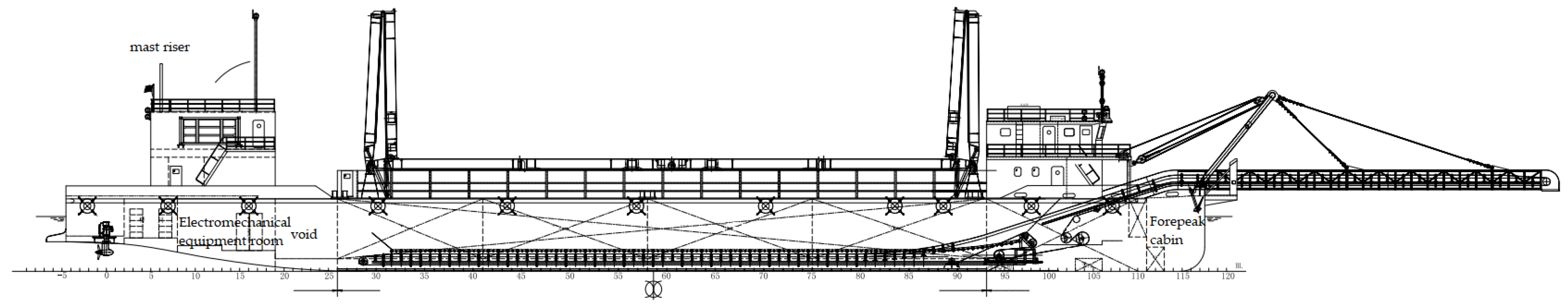
The quantitative risk assessment is a systematic method of quantitatively presenting the frequency and consequences of accidents in a certain facility or operation [21]. In the analysis process, not only the qualitative analysis of the cause, process, consequences and existing safety measures of the accident, but also the quantitative analysis of the accident frequency and consequences are required, and the analysis results are compared with the risk acceptance criteria to judge the acceptability of the risk [22]. If the requirements of risk acceptance criteria are not met, recommended measures to reduce risks shall be put forward. Quantitative risk assessment should include at least the following steps [23]: (1) data collection and sorting; (2) hazards identification: this step analyzes the causes and possible consequences of the hazards, and qualitatively determine the risk level; (3) failure scenario selection: according to the results of hazards identification, high-risk scenarios are selected for further quantitative analysis; (4) frequency analysis: based on the authoritative failure probability database, this step analyzes the equipment failure probability in the scenario; (5) consequence analysis: this phase establishes a model to analyze the consequences of the scenario; (6) risk assessment: The individual risk refers to the individual death probability of personnel at a specific location in the area caused by the accident. The individual risk model is shown in Equation (1) [24]:
R ( x , y ) = s = 1 N f s × V s ( x , y )
where, R(x,y) is the individual risk at the location of (x,y); fS is the probability of the s-th accident scenario; VS(x,y) is the probability of individual death caused by the s-th accident scenario at position (x,y); N is the total number of accidents.

2.2. Case Overview

In this paper, a 2000 DWT hydrogen powered ship is taken as an example to carry out a risk assessment of bunkering operations. The relevant parameters of the ship are shown in Table 1. The general layout of the ship is shown in Figure 1.
The hydrogenation station matched with the above hydrogen powered ship is 40 m long and 45 m wide, which is composed of the hydrogenation machine, the hydrogenation control room, the hydrogen storage bottles, the compressors, etc. The station uses the pressure of 35 MPa to bunker the hydrogen powered ship.

3. Results

3.1. Hazards Identification

The project team convened 15 industry experts to identify hazards for the ship’s bunkering operations, and referred to related literature [25,26], and finally identified 16 risk scenarios, including hose rupture, hard pipe rupture, valve leakage, overpressure of the bunkering system, too fast flow rate of the bunkering system, power loss of the ship, personnel improper operation, communication failures, etc. According to the qualitative analysis of the expert group, hose rupture, hard pipe rupture and valve leakage are high-risk hazards, and the rest of the scenarios are medium and low risk. According to this, only the analysis results of the high-risk scenarios are shown in Table 2, and further quantitative analysis is made for these three scenarios below.

3.2. Probability Analysis

For the determination of equipment failure probability, the general approach is to refer to relevant domestic and foreign databases [27]. Among them, the recognized more authoritative leak probability databases include the International Oil and Gas Producers Association (OGP), Health and Safety Executive (HSE), Offshore and Onshore Reliability Data (OREDA), Federal Energy Regulatory Commission (FERC) and other databases. Each database has a different scope of application. Combined with the characteristics of the object studied in this paper and the application range of each database, the failure probability of the remote valve is 4.2 × 10⁻⁵, the failure probability of the manual valve is 4.9 × 10⁻⁶, the failure probability of the small hole (5mm) of the pipe is 6.4 × 10⁻⁶, and the failure probability of complete rupture is 1 × 10⁻⁶. The hose failure probability is 1.2 × 10⁻⁴.
For the determination of the failure scenarios for the consequence analysis in the next step, according to the relevant provisions of the FERC, it points out that scenarios with a failure probability greater than 5 × 10⁻⁵ must be considered. It can be seen that only the failure probability of a hose rupture is greater than 5 × 10⁻⁵, so this paper will further analyze the failure consequences of the hose rupture hazard.

3.3. Consequence Analysis

3.3.1. Mathematical Model

After hydrogen leaks, it continuously mixes with air to form a turbulent flow. In this process, the flow of the mixed gas follows the continuity equation, the energy equation, the momentum equation, and each component follows the component transport equation. The above equation can be expressed in a general form [28], as shown in Equation (2):
( ρ ϕ ) τ + ( ρ u i ϕ ) x j = x j ( Γ ϕ x j ) + S
where, ϕ is a general variable; τ is the time; u j is the component of velocity along X, Y and Z directions; ρ is the density of the mixed gas; Γ is the diffusion coefficient; S is the source item.

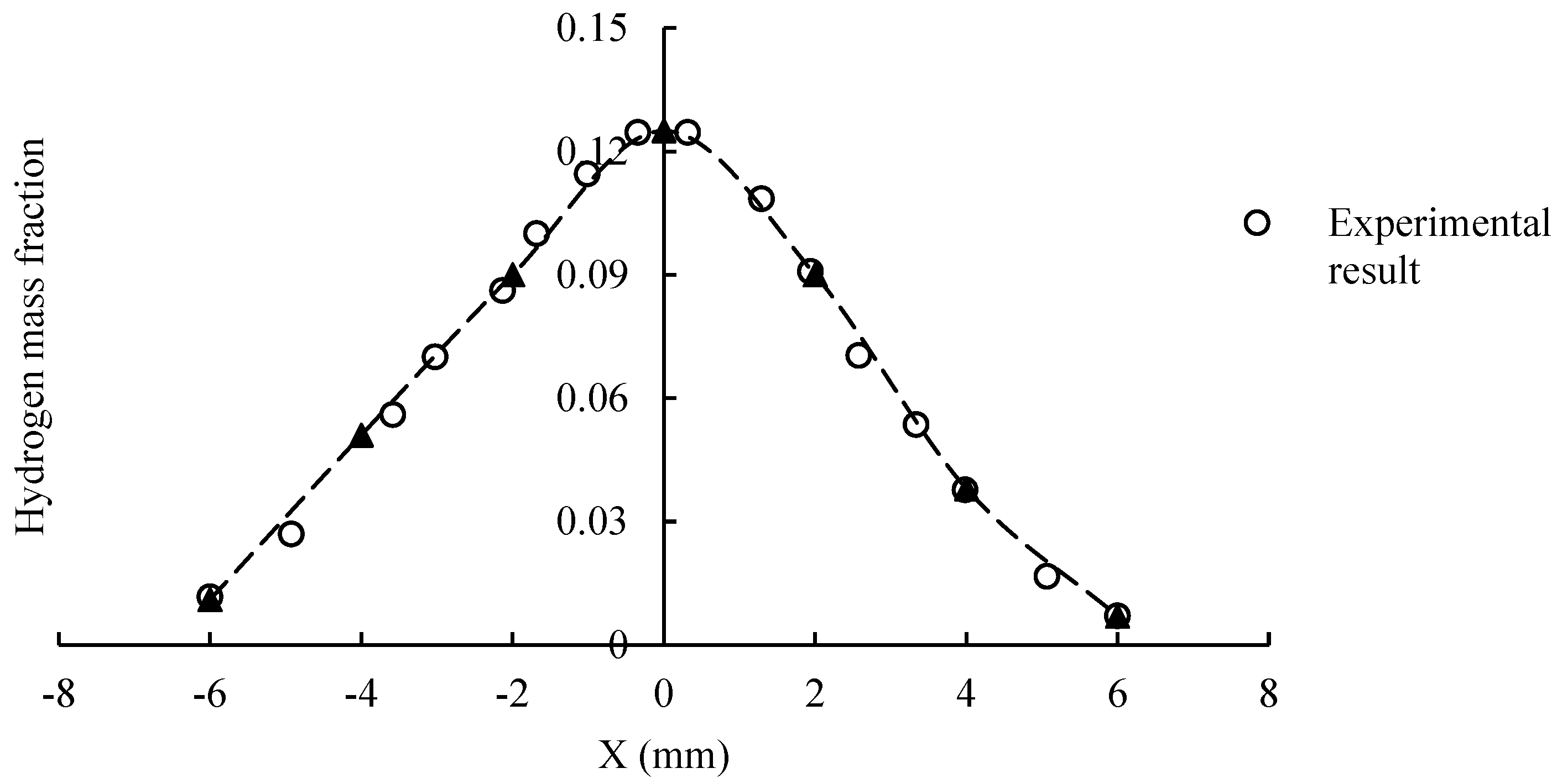
3.3.2. Comparison between the Experimental Results and the Simulation Results of Hydrogen Dispersion and Ventilation Module of FLACS Software

In order to verify the accuracy of the hydrogen dispersion and ventilation module of FLACS software, the FLACS simulation results are compared with the experimental results of hydrogen leakage jet [29,30]. In the experiment, the diameter of hydrogen pipe is 63.5 mm, the diameter of leakage port is 1.9 mm, the leakage speed is 133.9 m/s, the experimental environment is windless, the temperature is 21 °C, the atmospheric pressure is 100 kPa, and the radial hydrogen mass fraction concentration of vertical hydrogen jet at different axial positions along the jet centerline is obtained. The FLACS model under the same initial conditions is established, and the radial hydrogen mass fraction at the axial Z/D = 10 of the hydrogen jet is obtained. The experimental and simulation results are shown in Figure 2. It can be seen that the FLACS simulation results are in good agreement with the experimental results, and the reliability of the simulation results is high.

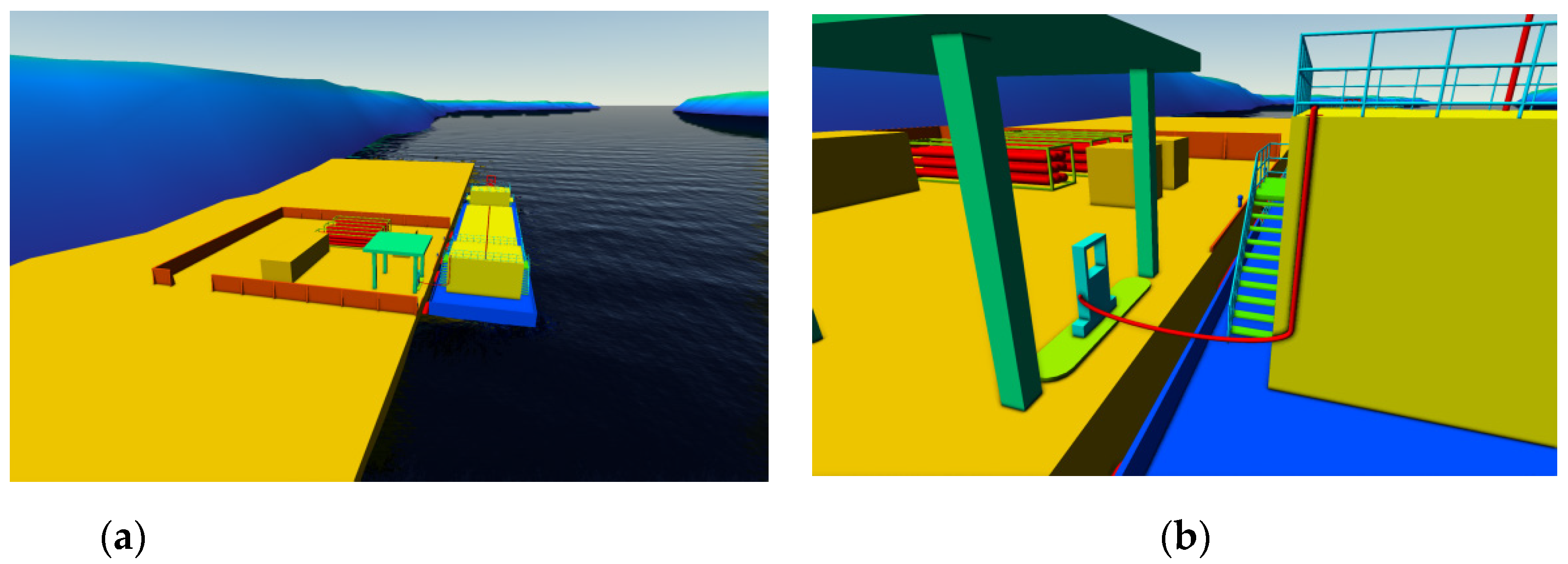
3.3.3. Simulation Model and Scene Description

According to the results of probability analysis, the FLACS software is used to model the actual scene of shore based bunkering operation of the hydrogen-powered ship. FLACS is a 3D CFD calculation software based on porosity technology, which integrates the data correction of actual tests conducted during the past 40 years and is used to simulate the diffusion of flammable gases, fires and explosions, etc. [31,32]. In the FLACS software, the 3D model of the hydrogen powered ship, the bunkering station and the surrounding environment is established, and the overall and partial models are shown in the Figure 3.
In the above case, the wind rose diagram of annual average wind speed and maximum wind speed in the bunkering operation area is shown in the Figure 4. The local average annual temperature is 21.8 °C, the average annual humidity is 76%, and the atmospheric stability is grade D. The failure scenario is the complete rupture of the bunkering hose between the ship and the shore, the pressure of the hydrogen pipeline is 35 MPa and the inner diameter of bunkering pipeline is 8.5 mm.

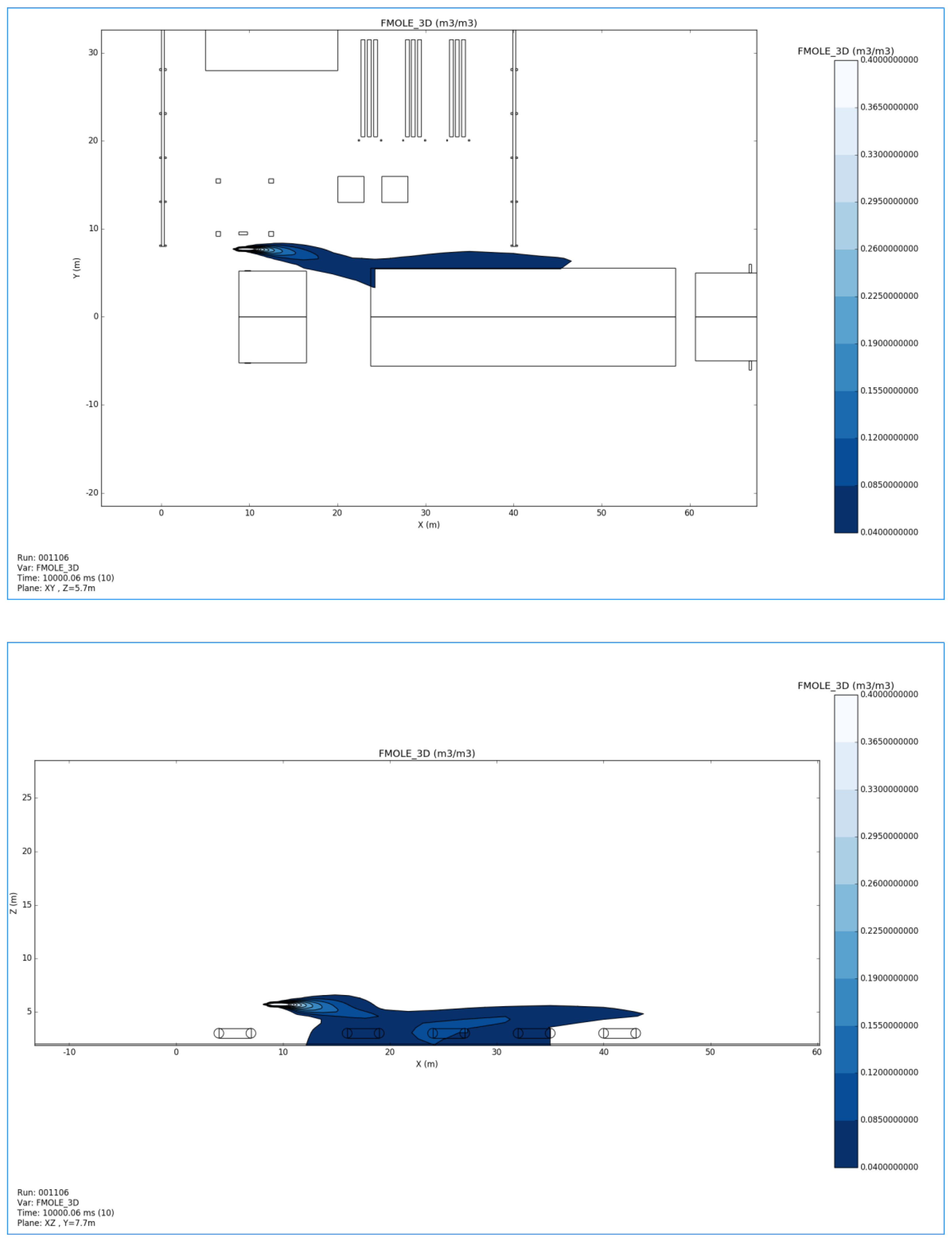
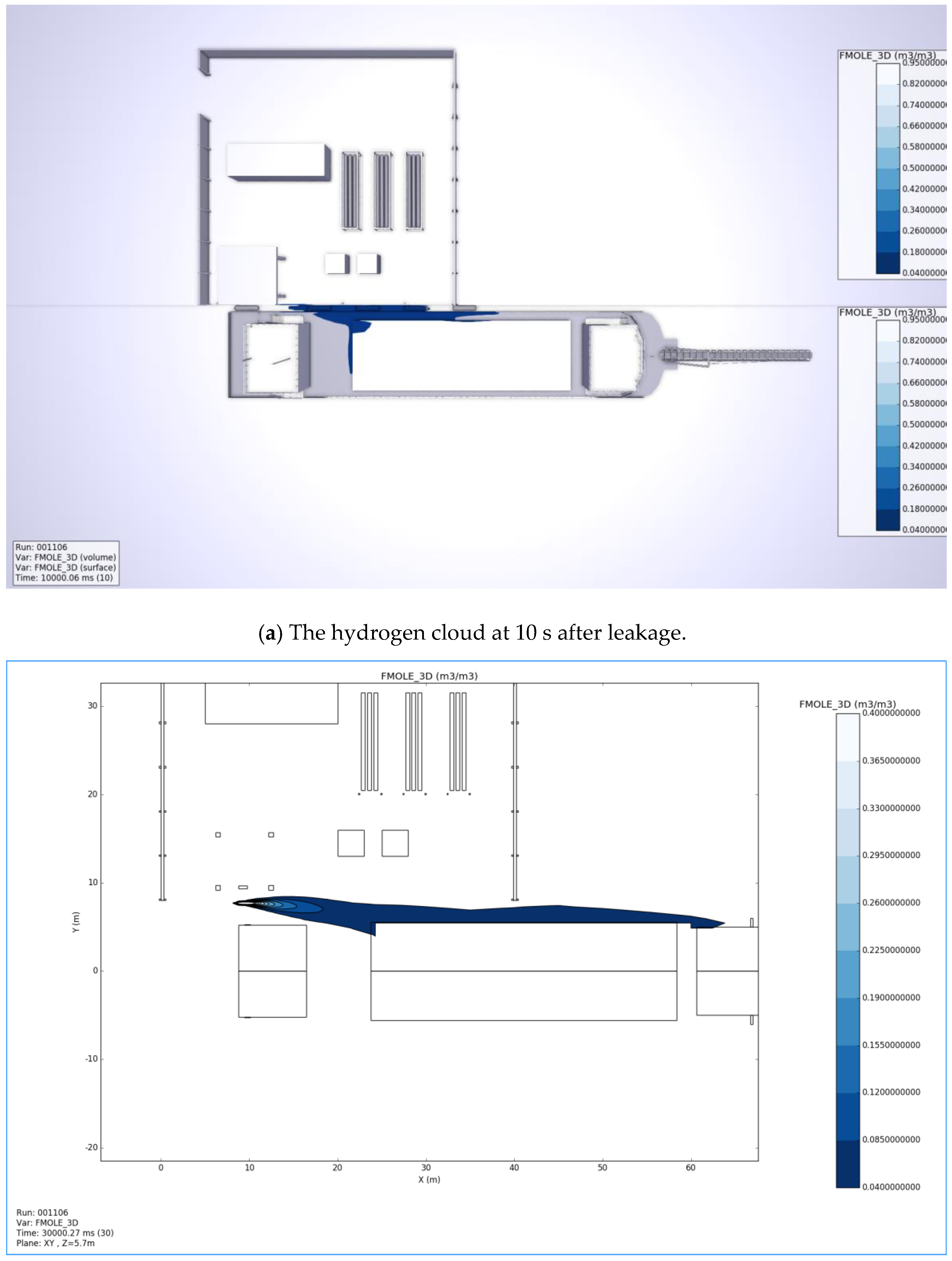
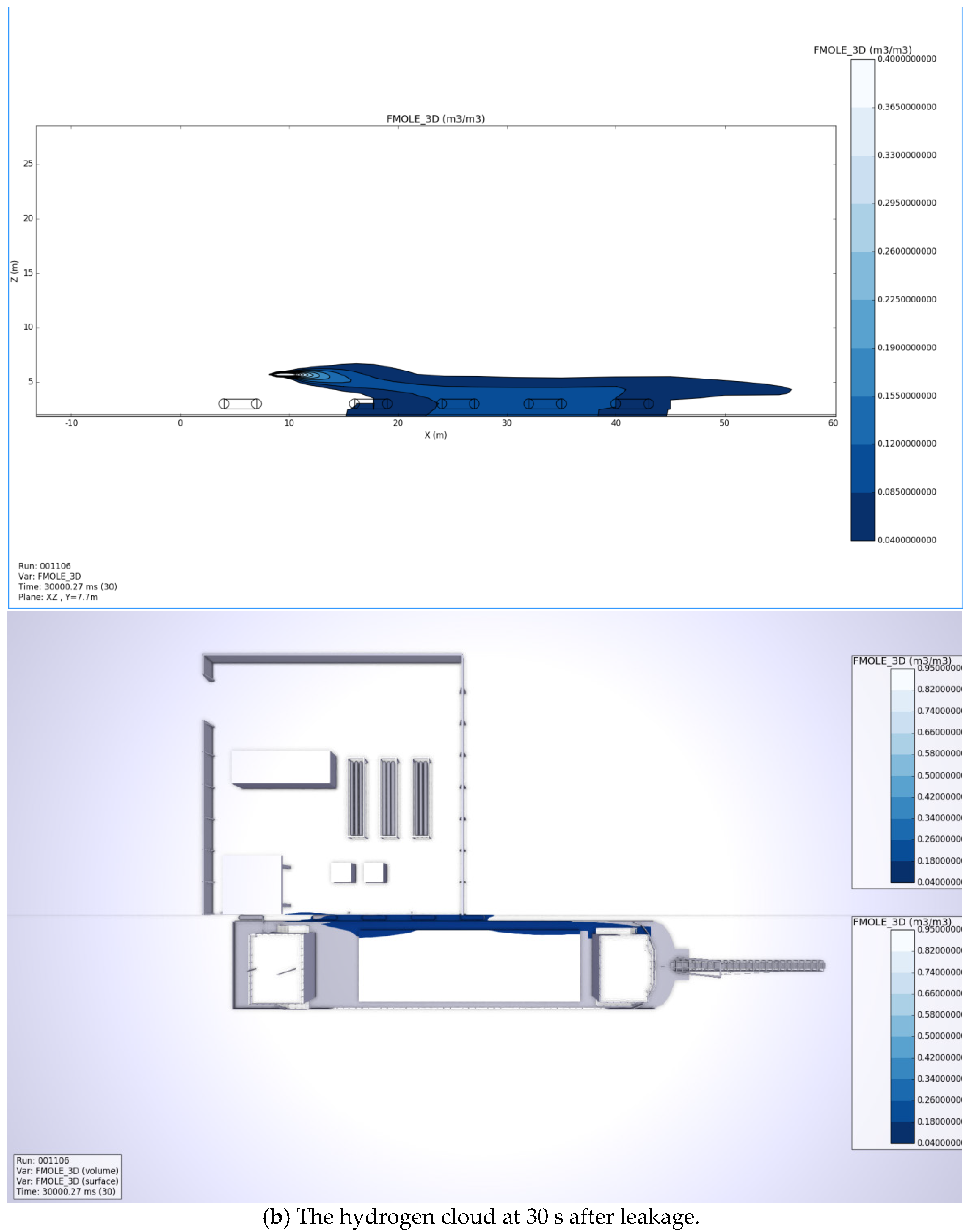
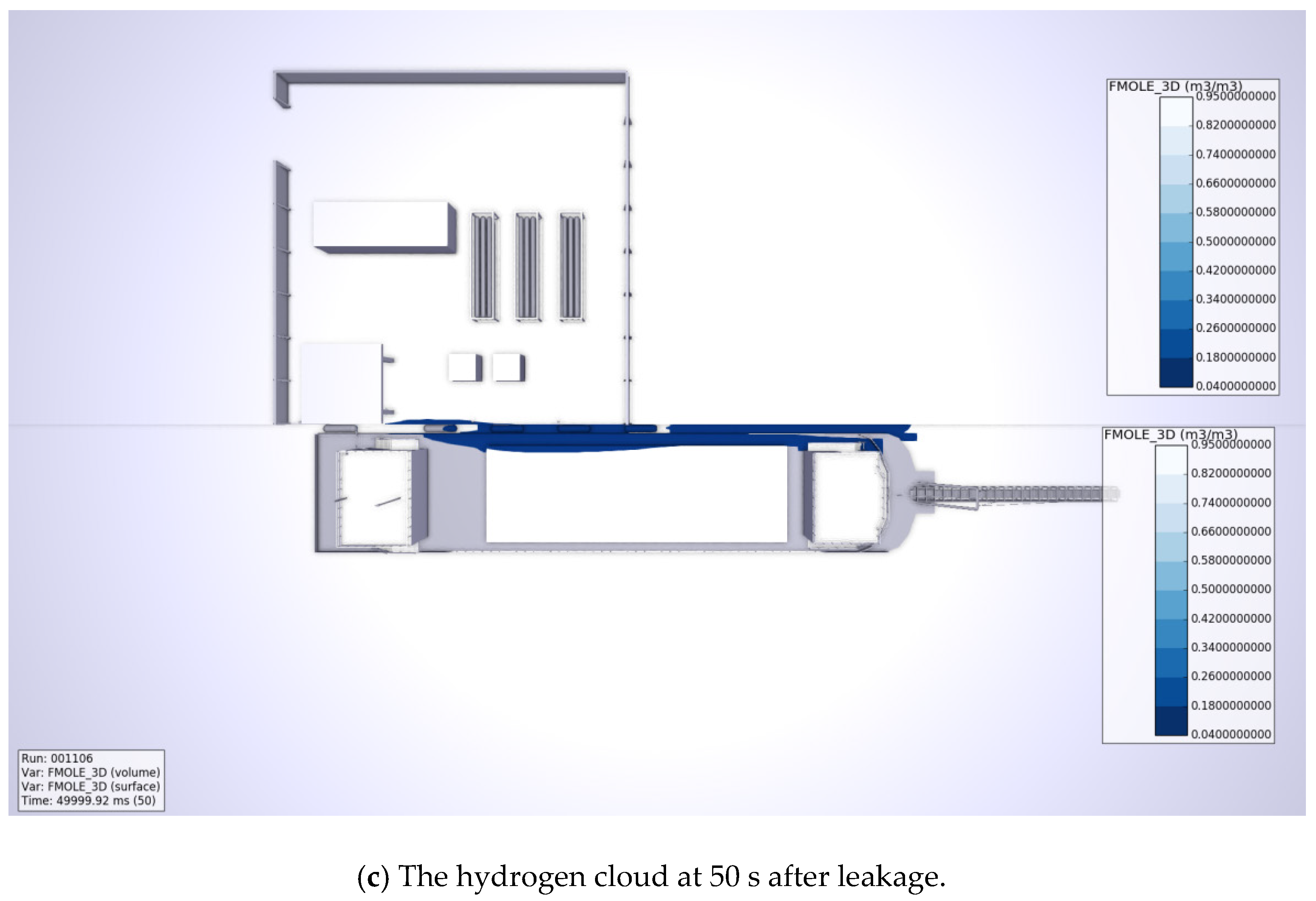
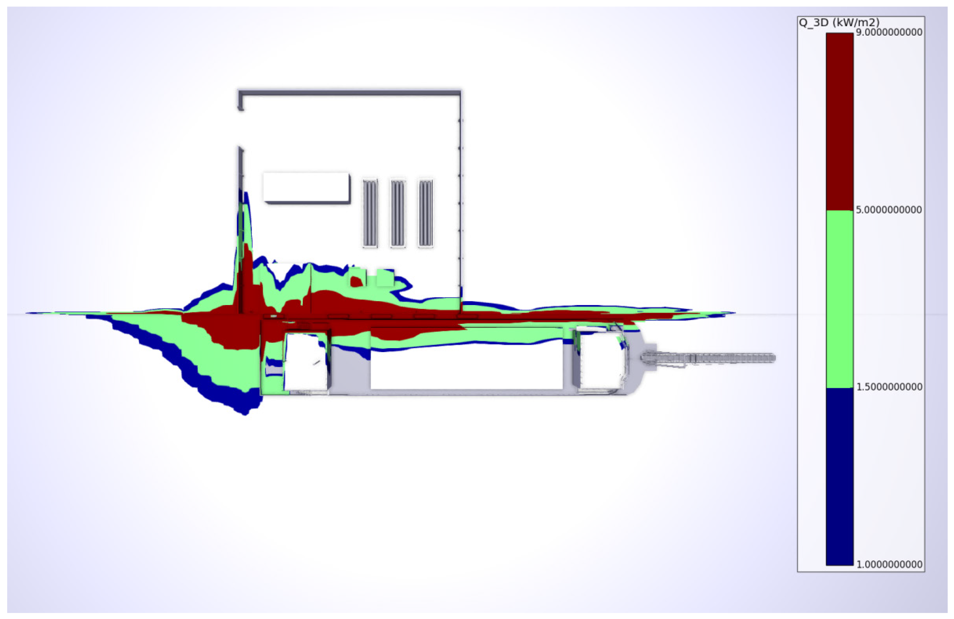
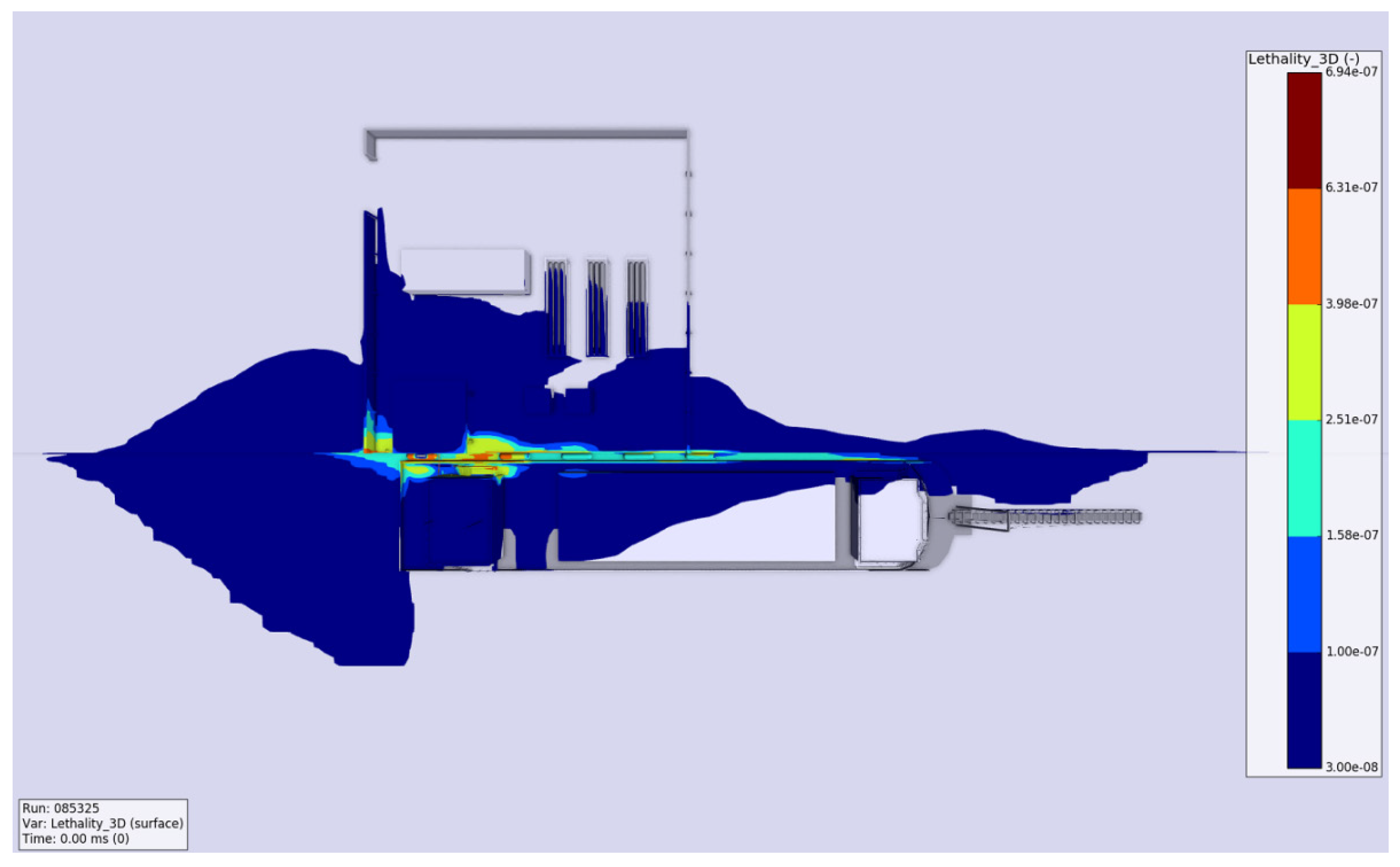
3.3.4. Consequence Simulation

The dispersion range of hydrogen after leakage is simulated by using the dispersion and ventilation module of the FLACS software, and the diffusion range at different time points is recorded. The cross-section, longitudinal section of the diffusion range of hydrogen cloud at 10 s, 30 s and 50 s after the occurrence of hydrogen fuel leakage are summarized as shown in the Figure 5. It can be seen that with the passage of time of leakage, the diffusion range of hydrogen cloud increases along with the direction of ship length, but changes are not obvious in the direction of ship width and ship height. This is due to the formation of a semi-enclosed space between the bunkering station and the hydrogen powered ship. Due to the existence of the narrow tube effect, when the airflow passes through this area, the horizontal wind speed increases, thus promoting the diffusion of hydrogen cloud in this area, and the diffusion of hydrogen in the direction of ship width and ship height is restrained to a certain extent.
In addition, according to the simulation results, under the above setting conditions, the instantaneous leakage speed of hydrogen can reach 782 m/s, which will have a huge injection reaction force on the hydrogenation hose. Besides, the pull-off valve is usually set near the hydrogenation station for hydrogen bunkering [33]. When the force exceeds the set value, the pull-off valve will automatically disengage. This will cause the long and flexible hydrogenation hose after leakage to swing at a high speed, threatening the safety of surrounding operators and facilities. Therefore, it can be considered to set appropriate protective measures for the hydrogenation hose, such as installing anti swing support or installing energy absorbing parts made of high-efficiency energy absorbing materials on the hose fixing device.
The fire module in FLACS software is used to simulate the ignition of combustible gas 60 s after hydrogen leakage. The thermal radiation distribution is shown in Figure 6.

3.3.5. The Determination of Safety Distance

Based on the literature research results [34,35] and combined with the actual situation of hydrogen bunkering, the thermal radiation thresholds of shore-based bunkering stations for hydrogen powered ships and buildings outside the stations are determined as follows: for the recommended safe distance between important public buildings, railways and bridges and shore-based bunkering station of hydrogen-powered ships, the larger value of diffusion distance at 0.5 LFL hydrogen concentration and thermal radiation influence distance at 1.5 kW/m2 is taken. For outdoor distribution power stations, class I protection for civil buildings, class-A and class-B production and storage plants, the diffusion distance of hydrogen under LFL concentration is taken; The thermal radiation influence distance of 5 kW/m2 is taken for the class II protection for civil buildings and the production and storage plants of class C, D and E. The thermal radiation influence distance of 9 kW/m2 is taken for the class III protection for civil buildings. On the basis of the above values and considering certain safety margin, the final recommended safe distance between shore-based bunkering station of hydrogen powered ship and buildings outside the station is shown in the Table 3. For the definition of buildings outside the station, please refer to GB 50156 [36].
In addition, according to the FLACS simulation results, the diffusion distance of LFL concentration of hydrogen gas is taken as the envelope to delimit the restricted area. During the bunkering operation, unrelated persons are not allowed to enter and strictly any ignition source in the restricted area. The restricted area scope is: 128 m along the length of the ship (from the bunkering station), 35 m along the width of the ship (from the bunker station), and 18 m in the vertical direction (from the main deck).

3.4. Risk Assessment

Referring to the No. 40 of the State Administration of Work Safety “Interim Provisions on the supervision and administration of major hazards of dangerous chemicals”, for the shore based bunkering operation of hydrogen powered ship, select 1 × 10⁻⁶/a is acceptable individual risk, 1 × 10⁻⁸/a is negligible individual risk. Based on the results of probability analysis and FLACS consequence simulation, it can be concluded that the maximum individual risk value of shore based bunkering operation is 6.9 × 10⁻⁷/a, which is within the ALARP region and necessary risk control measures need to be taken. The simulation results of the individual risk varying with distance from the risk source are shown in the Figure 7. It can be seen that the higher risk value appears in the middle slit between the hydrogen powered ship and the shore-based bunkering station, which is more consistent with the location where the hydrogen concentration is high in the leakage diffusion cloud map.

4. Conclusions and Recommendations

4.1. Conclusions

For all types of hydrogen powered ships, the following risk control measures are recommended to mitigate the risk:
(1)
Consider using the bunkering arm and hose as the hydrogen transmission channel between the ship and shore, so as to shorten the length of hose.
(2)
Appropriate protection measures against mechanical damage should be added to the pipes at the ship.
(3)
Regular maintenance of the valve and regular replacement of flange gasket.
(4)
A restricted area shall be set during bunkering operation, and the ignition source shall be controlled within the restricted area.
(5)
When the hose ruptures, the instantaneous leakage speed of hydrogen is very large, which may lead to hose swing and seriously threaten the safety of surrounding equipment and personnel. It can be considered to set up anti swing support or install energy absorbing parts on the hose fixing device to effectively realize anti swing protection.
For the hydrogen powered ship in this case, the following conclusions are drawn through the above research:
(1)
The personal risk of shore-based bunkering operations for hydrogen-powered ship is acceptable, but appropriate risk control measures need to be taken to mitigate the risk as much as possible;
(2)
The envelope of the bunkering restriction area is 128 m along the length of the ship (from the bunkering station), 35 m along the width of the ship (from the bunker station), and 18 m in the vertical direction (from the main deck). During the hydrogen bunkering operation, irrelevant personnel are prohibited to enter the area and any form of ignition source is prohibited.
(3)
The shore-based hydrogen bunkering station should maintain a certain safe distance from the buildings outside the station. After risk assessment, it is recommended that the safe distance to important public buildings, railways and bridges is 150 m, and the safe distance to civil buildings is 120 m~135 m, the safe distance from the production and storage plant is 125 m~135 m.

4.2. Recommendations

In this paper, the traditional risk assessment method is used to conduct quantitative risk assessment on the emerging ship type, and some risk control measures to mitigate the risk are obtained. However, there are still some deficiencies to be further studied in the follow-up:
(1)
With the deepening of the understanding of the risk of bunkering operation of hydrogen powered ships, the innovative risk assessment theory for the new-type ship still needs to be further studied.
(2)
There are too few real ship application cases of hydrogen powered ships in the world, and the accumulation of failure data is still insufficient. Therefore, at present, the existing mature database is mainly used for reference. After the application experience has accumulated to a certain extent, the failure probability analysis and correction for this new type ship can be considered.
(3)
In the consequence simulation part, this paper uses the FLACS software to simulate the leakage and diffusion during the bunkering process. In the future research, experimental methods can be considered to carry out related experimental research.

Author Contributions

Methodology, Y.F.; software, J.C.; investigation, Y.Z. and D.J. All authors have read and agreed to the published version of the manuscript.

Funding

TThis research was funded by the project of the ministry of industry and information technology of China “Research on Key Technologies of hydrogen fuel powered ship”.

Data Availability Statement

Publicly archived datasets were analyzed in this study, and can be found at the following: Annual offshore statistics and regulatory activity report, 2019 Final, Health and Safety Executive (HSE), https://www.hse.gov.uk/offshore/statistics/index.htm (accessed on 2 June 2021). Risk assessment data directory—Process release frequencies, 2019 Final, IOGP 434-01 report, International Association of oil gas Producers (IOGP), https://www.iogp.org/bookstore/browse/ (accessed on 10 June 2021). Offshore & onshore reliability data, OREDA, https://www.oreda.com/ (accessed on 12 June 2021).

Conflicts of Interest

The authors declare no conflict of interest.

References

  1. Ji, C.; El-Halwagi, M.M. A data-driven study of IMO compliant fuel emissions with consideration of black carbon aerosols. Ocean Eng. 2020, 218, 108241. [Google Scholar] [CrossRef]
  2. Offer, G.J.; Howey, D.; Contestabile, M.; Offer, G.J.; Clague, R.; Brandon, N.P. Comparative analysis of battery electric, hydrogen fuel cell and hybrid vehicles in a future sustainable road transport system. Energy Policy 2010, 38, 24–29. [Google Scholar] [CrossRef] [Green Version]
  3. Shi, G.; Zhang, H. Study on fuel bunkering mode of natural gas fueled power ship. Ship Sea Eng. 2013, 6, 57–60. [Google Scholar]
  4. Jin, Y.; Cheng, B. An intelligent replaceable on-board hydrogen tank. China: 110789333A, 14 February 2020. [Google Scholar]
  5. Li, F. Design of Hydrogen System and Numerical Simulation of Hydrogen Leakage of Fuel Cell Passenger Ship; Wuhan University of technology: Wuhan, China, 2018. [Google Scholar]
  6. Lu, L.; Liu, M.; Lu, J.; Liu, X. Study on ship shore LNG transmission speed of inland river LNG shore-based bunkering station. China Water Transp. 2019, 615, 46–47. [Google Scholar]
  7. Milazzo, M.F.; Bragatto, P. A framework addressing a safe ageing management in complex industrial sites: The Italian experience in «Seveso» establishments. J. Loss Prev. Process Ind. 2019, 58, 70–81. [Google Scholar] [CrossRef]
  8. Yacine, B.; Mébarek, D.; Hefaidh, H. Contribution to the ageing control of onshore oil and gas fields. Petroleum 2020, 6, 311–317. [Google Scholar] [CrossRef]
  9. Iannaccone, T.; Jeong, B.; Cozzani, V.; Zhou, P. Safety Analysis of Liquefied Natural Gas Bunkering and Simultaneous Port Operations for Passenger Ships. In ASME 2020 39th International Conference on Ocean, Proceedings of the Offshore and Arctic Engineering, Online, 3–7 August 2020; American Society of Mechanical Engineers: New York, NY, USA, 2020. [Google Scholar]
  10. Yan, M. Risk Identification and Risk Analysis of LNG Filling Operation; Jiangsu University of Science and Technology: Zhenjiang, China, 2018. [Google Scholar]
  11. Fan, H.; Cheng, K.; Wu, S. CFD Based Simulation of LNG Release during Bunkering and Cargo Loading/Unloading Simultaneous Operations of a Containership. J. Shipp. Ocean Eng. 2017, 7, 51–58. [Google Scholar]
  12. Chen, L.; Dou, L. Discussion on safety management of water refueling on distribution ship. Saf. Health Environ. 2012, 12, 47–49. [Google Scholar]
  13. Zhu, B.; Li, C. Research on Stability Simulation of safe operation of tanker. Ship Eng. 2011, 33, 25–28. [Google Scholar]
  14. Wang, T.; Wu, Q.; Diaconeasa, M.A.; Yan, X.; Mosleh, A. On the Use of the Hybrid Causal Logic Methodology in Ship Collision Risk Assessment. J. Mar. Sci. Eng. 2020, 8, 485. [Google Scholar] [CrossRef]
  15. Parhizkar, T.; Utne, I.B.; Vinnem, J.E.; Mosleh, A. Supervised dynamic probabilistic risk assessment of complex systems, part 2: Application to risk-informed decision making, practice and results. Reliab. Eng. Syst. Saf. 2021, 208, 107392. [Google Scholar] [CrossRef]
  16. Zheng, K.; Chen, Y.; Jiang, Y.; Qiao, S. A SVM based ship collision risk assessment algorithm. Ocean Eng. 2020, 202, 107062. [Google Scholar] [CrossRef]
  17. Wang, C. Study on Environmental Safety Risk Assessment System of Hydrogenation Station; Shanghai Jiaotong University: Shanghai, China, 2016. [Google Scholar]
  18. Zhang, C. Research on Risk Assessment of Fuel Cell Vehicle Hydrogenation Station; Chongqing University: Chongqing, China, 2019. [Google Scholar]
  19. Kikukawa, S.; Mitsuhashi, H.; Miyake, A. Risk assessment for liquid hydrogen fueling stations. Int. J. Hydrog. Energy 2009, 34, 1135–1141. [Google Scholar] [CrossRef]
  20. Li, Z.; Xiangmin, R.; Jianxin, R. Quantitative risk assessment on a gaseous hydrogen refueling station in Shanghai. Int. J. Hydrog. Energy 2010, 35, 6822–6829. [Google Scholar]
  21. Antonioni, G.; Spadoni, G.; Cozzani, V. A methodology for the quantitative risk assessment of major accidents triggered by seismic events. J. Hazard. Mater. 2007, 147, 48–59. [Google Scholar] [CrossRef]
  22. Dian, L.I.; Tang, W.; Zhang, S. Review of risk acceptance criteria for ocean engineering. Ocean Eng. 2003, 21, 96–102. [Google Scholar]
  23. Antonioni, G.; Spadoni, G.; Cozzani, V. Application of domino effect quantitative risk assessment to an extended industrial area. J. Loss Prev. Process Ind. 2009, 22, 614–624. [Google Scholar] [CrossRef]
  24. AQT 3046-2013. Guidelines for Quantitative Risk Assessment of Chemical Enterprises; China Planning Press: Beijing, China, 2013. [Google Scholar]
  25. Lu, L.; Liu, M.; Shi, G. Study on risk analysis and preventive measures of LNG tanker. China Water Transp. 2019, 609, 45–47. [Google Scholar]
  26. Yan, M. Risk Identification of LNG Bunkering Ship and Risk Analysis of Bunkering Operation; Jiangsu University of science and technology: Nanjing, China, 2018. [Google Scholar]
  27. Yuan, J. Analysis of Petrochemical Tank Farm Safety Measures and Its Impact on Quantitative Risk; China University of Petroleum: Qingdao, China, 2014. [Google Scholar]
  28. Yu, Y.; Deng, Y. Hydrogen leakage and diffusion in high voltage chamber of fuel cell bus. J. Zhejiang Univ. (Eng. Sci.) 2020, 54, 381–387. [Google Scholar]
  29. Houf, W.; Schefer, R. Analytical and experimental investigation of small-scale unintended releases of hydrogen. Int. J. Hydrog. Energy 2008, 33, 1435–1444. [Google Scholar] [CrossRef]
  30. Schefer, R.; Houf, W.; Williams, T. Investigation of small-scale unintended releases of hydrogen: Momentum-dominated regime. Int. J. Hydrog. Energy 2008, 33, 6373–6384. [Google Scholar] [CrossRef]
  31. Hansen, O.R.; Gavelli, F.; Ichard, M.; Davis, S.G. Validation of FLACS against experimental data sets from the model evaluation database for LNG vapor dispersion. J. Loss Prev. Process Ind. 2010, 23, 857–877. [Google Scholar] [CrossRef]
  32. Wang, R.J. Establishing 3D model and Simulating explosion accident of LNG powered ship. J. Saf. Sci. Technol. 2013, 9, 73–77. [Google Scholar]
  33. China Classification Society. Guidelines for Ships Using Alternative Fuels; China Communications Press: Beijing, China, 2017. [Google Scholar]
  34. Wu, Z.; Dang, W. Research on the method of determining the external safety distance of water LNG bunkering stations. Saf. Health Environ. 2017, 17, 40–43. [Google Scholar]
  35. Wan, G.; Dang, W.; Wu, Z.; Lin, X. Study on determination method of safety distance of LNG filling barge. Chin. J. Saf. Sci. 2015, 25, 110–115. [Google Scholar]
  36. GB 50156-2012. Code for Design and Construction of Filling Station; China Planning Press: Beijing, China, 2012. [Google Scholar]
Figure 1. The general layout of a hydrogen powered ship.
Wevj 12 00162 g001
Figure 2. The experimental and simulation results of radial hydrogen mass fraction at Z/D = 10 of hydrogen jet.
Wevj 12 00162 g002
Figure 3. The overall and partial model of FLACS for shore-based bunkering operation for the hydrogen powered ship. (a) The Overall FLACS model; (b) The partial FLACS model.
Wevj 12 00162 g003
Figure 4. The wind rose diagram of annual average wind speed and maximum wind speed in the bunkering operation.
Wevj 12 00162 g004
Figure 5. The cross section, longitudinal section and overall diffusion range of hydrogen cloud at different time points after leakage.
Wevj 12 00162 g005aWevj 12 00162 g005bWevj 12 00162 g005cWevj 12 00162 g005dWevj 12 00162 g005e
Figure 6. The distribution of fire thermal radiation in shore based bunkering operation for hydrogen powered ship.
Wevj 12 00162 g006
Figure 7. The individual risk varying with distance from the risk source.
Wevj 12 00162 g007
Table 1. The main parameters of the hydrogen powered ship.
NameParameter
Ship length70.5 m
Ship width13.9 m
Depth4.5 m
Draft3.1 m
Hydrogen cylinder and hydrogen storage36 bottles, single bottle 320 L, 35 MPa, total 280 kg
Bunkering pipe diameterHigh pressure gas phase (outer diameter 12.7 mm, inner diameter 8.5 mm)
Fuel cell system4 × 135 kW, a total of 540 kW, PEMFC
Lithium battery capacity4 × 315 kW h, a total of 1260 kW h
Design speed13.0 km/h
Endurance140 km
Table 2. Identification table of the main hazards for shore-based bunkering system for hydrogen powered ships.
Main HazardsCauseConsequenceExisting Safety MeasuresRecommended Measure
Hose rupture
  • The ship/shore relative motion is too large;
  • The bending radius is too small;
  • Aging corrosion;
  • Fatigue failure;
  • Improper storage;
  • The hose is not properly supported.
Hydrogen leakage and diffusion, fire and explosion in case of ignition source.
  • ESD cut off the bunkering pipeline on board;
  • Onshore ESD cut off the hydrogen supply;
  • Firefighting system.
  • No bunkering operation in windy weather;
  • It is suggested that the hose should be firmly supported before bunkering;
  • Leak detection before bunkering operation;
  • Set up the restricted area, control the ignition source in the restricted area;
  • Consider using hydrogen bunkering arm and hose to reduce the length of hose.
Rupture of hard pipe
  • Falling objects;
  • Collision.
Hydrogen leakage and diffusion, fire and explosion in case of ignition source
  • ESD cut off the bunkering pipeline on board;
  • Onshore ESD cut off hydrogen supply;
  • Firefighting system.
  • It is suggested to set up proper protection against mechanical damage;
  • Set up the restricted area, control the ignition source in the restricted area.
Valve leakage
  • Seal failure;
  • Fatigue failure;
  • Strength failure;
  • Improper operation.
Hydrogen leakage and diffusion, fire and explosion in case of ignition source
  • Equipped with ESD system;
  • Combustible gas leakage detection alarm;
  • Firefighting system;
  • The material selection of valves is reasonable;
  • Adopt approved valve parts.
  • Replace flange gasket regularly;
  • Leak detection before operation;
  • Regular maintenance and replacement of valves
  • Set up the restricted area, control the ignition source in the restricted area.
Table 3. The recommended safe distance between shore-based bunkering station for hydrogen powered ships and buildings outside the stations.
Names of Buildings Outside the StationRecommended Safe Distance
Major Public Buildings150 m
Civil building protection categoryClass I135 m
Class II125 m
Class III120 m
Class A and Class B production and storage plants135 m
Class C, D, E production and storage plan125 m
Outdoor distribution station135 m
Railway150 m
Bridge150 m
Publisher’s Note: MDPI stays neutral with regard to jurisdictional claims in published maps and institutional affiliations.

