Article

Research on Coil Identification Algorithm of Wireless Power Transfer System Based on Magnetic Field Features

1
School of Automation, Nanjing University of Science and Technology, Nanjing 210094, China
2
Maintenance Branch Company, State Grid Jiangsu Electric Power Co., Ltd., Nanjing 211102, China
*
Author to whom correspondence should be addressed.
World Electr. Veh. J. 2021, 12(3), 140; https://doi.org/10.3390/wevj12030140
Submission received: 1 August 2021 / Revised: 26 August 2021 / Accepted: 30 August 2021 / Published: 1 September 2021

Abstract

:
In the practical application of wireless power transfer (WPT), the identification of the secondary coil and the analysis of the space magnetic field of the coil will affect the matching scheme of the coil, which will further affect the performance of energy transmission. At present, the establishment of the coil space magnetic field model mainly adopts the finite element method (FEM). The accuracy of the results is limited by the computer performance and the specific settings during calculation, which usually takes a long time. Additionally, it can only analyze and establish the space magnetic field of the coil with specific parameters. Especially when the coil structure and parameters change, it is difficult to quickly establish the spatial magnetic field. This paper presents a secondary side coil identification method of a wireless charging system based on the magnetic field cloud image characteristics. The image feature extraction algorithm is used to extract features of a certain height magnetic field cloud image of an unknown structure type coil obtained by FEM. Further, by matching with the characteristics of the magnetic field cloud image of the known coil, the identification of the unknown coil structure type is realized. The effectiveness and accuracy of the proposed method is verified by an example. This algorithm is helpful to extract the characteristics of the coil space magnetic field, and can establish coil space magnetic field models with different structure types and different coil parameters combined with deep learning to guide the matching scheme of the primary and secondary coils, and realize efficient energy transmission.

1. Introduction

Wireless power transfer (WPT) technology has been rapidly developed in recent years as a flexible and convenient new charging method. It is a transmission mode that transfers electric energy from the power source to the power consumer by means of an invisible soft medium in space (such as electric field, magnetic field, sound wave, etc.). Among the current WPT methods, the most theoretical research and the faster application process is mainly the magnetic coupling wireless power method [1]. The current research on magnetic coupling WPT in the industry mainly focuses on system transmission characteristics, coupling mechanism design, electromagnetic shielding, and foreign body detection, etc. [2,3,4,5]. In the design of the coupling mechanism, various designs such as circular coils, square coils, spiral coils, DD (Double-D type) coils [6], and composite coils have emerged. Different coils have different magnetic field characteristics. The electromagnetic shielding, electromagnetic exposure, and electromagnetic environment of the coils are different. In the evaluation, the finite element method (FEM) is generally used to check the distribution of the magnetic field cloud map near the coil. Compared with the analytic results, the magnetic field cloud images obtained by FEM calculation are more intuitive and efficient. The characteristics of the magnetic field distribution of the coil can be found, and the information contained in it is also richer, which is deeply loved by researchers. However, the current researches are performed on known coils to obtain a cloud map of magnetic field distribution. The magnetic field cloud map contains information such as magnetic induction intensity values and magnetic field distribution rules at different spatial locations. The information contained in the magnetic field distribution cloud map can be used to obtain more information, such as identifying unknown coil types and sizes, and using magnetic field distribution to obtain magnetic field requirements to guide coils design and matching of primary and secondary coils and other functions. In addition, there are some electromechanical devices that use a multi-coil network structure that also need to analyze their magnetic field distribution to assist in improving the control strategy of the system [7]. At present, in the fields of atmospheric observation and geographic information systems, researchers have realized weather prediction and geological activity prediction through the analysis of remote sensing images, but few scholars have adopted the idea of image processing to analyze magnetic field cloud images.
This paper analyzes the magnetic field cloud images obtained by the FEM and proposes research on the secondary coil recognition algorithm of the wireless charging system based on the characteristics of the magnetic field cloud image. The identification is performed by analyzing the image pixel changes of the cloud image and the contour characteristics of the isomagnetic induction intensity line. To guide the design of the coil and the matching mechanism of the primary and secondary sides and even analyze the dynamic change law of the magnetic field, the first thing is to obtain the characteristics of the magnetic field near a single coil in a static state to realize the identification of the coil type. In the future, through deep learning and other methods, we hope to establish a magnetic field distribution point cloud model library of different coils and different sizes, to realize the identification of unknown coil type, size, and other parameters, and through this method, we hope to further study the magnetic field distribution help to guide the design of the coil and the matching mechanism of the primary and secondary sides. In Section 1, we mainly introduce the current research situation of coil recognition in the field of wireless power transmission and proposes a coil recognition algorithm of wireless charging system based on the characteristics of magnetic field cloud image. In Section 2, the basic algorithm of image recognition is introduced. In Section 3, based on the cloud image characteristics of the WPT coil, we designed the secondary coil identification algorithm flow of the wireless charging system based on the magnetic field cloud image characteristics. In Section 4, we conducted experiments on the algorithm to verify the feasibility of the algorithm proposed in this article. According to the proposed algorithm, we can distinguish the coil polarity through the changes of pixel value of the symmetrical axis along the Y direction of the unknown coil cloud image, and obtain the unknown coil type by judging the similarity of the contours from template sets and test sets. In Section 5, we have summarized the content of the full text and put forward some thoughts on the follow-up work.

2. Principles of Image Recognition Algorithm

2.1. Subsection

Histograms are widely used in many computer vision applications to detect changes in scenes by marking significant edge and color statistical changes between images. Set a “label” composed of a histogram with similar features at each point of interest to determine the point of interest in the image. Histograms such as edges, colors, and angles constitute a common feature type that can be passed to the target recognition classifier. The histogram sequence of colors and edges can also be used to identify whether the network video has been copied.
To put it simply, the histogram is a method of visualizing statistical data, and the statistical values are organized into a series of implementation-defined bins. The value is the feature statistics calculated from the data, these data can be such as gradient, direction, color, or any other features. In any case, the histogram obtains a statistical graph of the data distribution. Usually, the dimensionality of the histogram is lower than the original data. If a matrix contains information about an image, it is known that the range of each number contains 256 values from 0 to 255, so this range can be divided into sub-regions according to certain rules, such as:
[ 0 , 255 ] = [ 0 , 15 ] [ 16 , 31 ] [ 240 , 255 ]
r a n g e = b i n 1 b i n 2 b i n n = 15
Then count the number of pixels in each bin to obtain the histogram of the image. The histogram of the image can realize simple analysis and search of image similarity and can realize image segmentation through back projection. As the image content of the magnetic field cloud image of the secondary coil in the WPT system is relatively simple, the color distribution is relatively regular, and the connected area within the same color range is large, it is more convenient to use the back projection based on histogram to achieve image segmentation. Common histogram metric matching methods are as follows: N is the quantization level, H(i) is the pixel value.
  • Correlation:
d ( H 1 , H 2 ) = i ( H 1 ( i ) H ¯ 1 ( i ) ) ( H 2 ( i ) H ¯ 2 ( i ) ) i ( H 1 ( i ) H ¯ 1 ( i ) ) 2 i ( H 2 ( i ) H ¯ 2 ( i ) ) 2
H ¯ k = 1 N j H k ( J )
  • Chi-Square:
d ( H 1 , H 2 ) = I ( H 1 ( I ) H 2 ( I ) ) 2 H 1 ( I )
  • Intersection:
d ( H 1 , H 2 ) = I min ( H 1 ( I ) , H 2 ( I ) )
  • Bhattacharyya distance
d ( H 1 , H 2 ) = 1 1 H ¯ 1 ( I ) H ¯ 2 ( I ) N I H 1 ( I ) · H 2 ( I )

2.2. Contour Matching Algorithm

Contour is a good external feature of an image target. This feature is of great significance for deeper processing such as image analysis, target recognition, and understanding. Simply put, an outline is a series of points connected to form a shape, and they have the same color. Contour discovery is a very useful tool in image object analysis and object detection.
Based on contour recognition, it is necessary to split the image into channels, find edges, and convert them into contours (polygon approximation, feature generalization, etc.), and then perform contour matching (image and image matching, image, and template matching).
Contour matching is mainly used to solve the matching problems between images with different sizes, positions, rotation angles, and accuracy. Methods include contour moments, paired geometric histograms, convex hulls and convex defects, level matching and so on. Since the content of the magnetic field cloud image of WPT system is simple and the shape feature is relatively prominent, the contour moment is mainly used as the feature of shape matching.
The n-th moment of the real function relative to the value c is:
μ n = + ( x c ) n f ( x ) d x
The moments used in contour processing are mainly used in statistics.
The above formula is a one-element case, and it is extended to the two elements where the picture is located. For an image matrix, after finding the edge and converting the contour, the value of each value point f(x,y) in the matrix is either 0 (not a contour point), or 1 (it is the contour point), when f(x,y) is 0, the integral term is also 0, so we do not need to calculate it. Therefore, only f(x,y) = 1 is meaningful to us n points are contour points. In the following formula, it is denoted as I(x,y), x,y are the coordinates in the figure, and point c is extended to binary, which can be regarded as the center point of the contour. The so-called n-th order central moment obtained is just as shown in the above formula; the weight of the integral is the nth power of each point on the contour relative to the center position c.
At this time, we can obtain some statistical laws, such as: contour boundary length (zero-order moment), mean value in the x/y direction (i.e., centroid, calculated from the first-order moment), variance (calculated from the second-order central moment), shape characteristics (Hu moment)
Commonly used moments include space moment, center distance, normalized center distance, and shape moment, etc.
Spatial moments can only be used to compare contours with the same position, size, and angle, such as Equation (9):
m p , q = i = 1 n I ( x , y ) x p y q
mp,q represents the moment of (p + q) order of the image, and generally calculates all moments of order 3 (p + q ≤ 3).
Where I(x,y) is the value of the pixel (x, y), generally 1, n is the number of points on the contour, p and q are the moments in the x and y dimensions, namely m00, m10, m01...m03.
The zero-order moment m00 is a simple accumulation of points on the contour, that is, how many points are there on the contour.
The first moments m10 and m01 are the accumulation in the x and y directions.
The central moment, xavg and yavg are calculated from the ratio of the first-order moment and the zero-order moment. It is the coordinate of the center of gravity. The center moment is the moment obtained from the relative position of x, y, and the center of gravity. It makes the result and the image relative to x, The position of the y axis has nothing to do with translation
μ p , q = i = 1 n I ( x , y ) ( x x a v g ) p ( y y a v g ) q
x a v g = m 10 / m 00
y a v g = m 01 / m 00
The normalized central moment uses the power of m00 to normalize the central distance, making the result independent of the image size. The formula is as follows:
η p , q = μ p , q m 00 ( p + q ) / 2 + 1
The Hu invariant moment is a linear combination of the normalized center distance. It is invariant to scaling, rotation, and mirror mapping, and is suitable for shape matching of magnetic field cloud images. The formula is as follows:
h 1 = η 20 + η 02 h 2 = ( η 20 η 02 ) 2 + 4 η 11 2 h 3 = ( η 30 3 η 12 ) 2 + ( 3 η 21 η 03 ) 2 h 4 = ( η 30 + η 12 ) 2 + ( η 21 + η 03 ) 2 h 5 = ( η 30 3 η 12 ) ( η 30 + η 12 ) [ ( η 30 + η 12 ) 2 3 ( η 21 + η 03 ) ] + ( 3 η 21 η 03 ) ( η 21 + η 03 ) [ 3 ( η 30 + η 12 ) 2 ( η 21 + η 03 ) 2 ] h 6 = ( η 20 η 02 ) [ ( η 30 + η 12 ) 2 ( η 21 + η 03 ) 2 ] + 4 η 11 ( η 30 + η 12 ) 3 ( η 21 + η 03 ) h 7 = ( 3 η 21 η 03 ) ( η 21 + η 03 ) [ 3 ( η 30 + η 12 ) 2 ( η 21 + η 03 ) 2 ] ( η 30 3 η 12 ) ( η 21 + η 03 ) [ 3 ( η 30 + η 12 ) 2 ( η 21 + η 03 ) 2 ]
By calculating and comparing Hu invariant moments, the similarity of the contours can be obtained. Define the similarity S of the two contours of A and B as
S ( A , B ) = max i = 1 7 | m i A m i B | | m i A |
where
m i A = s i g n ( h i A ) · log h i A
m i B = s i g n ( h i B ) · log h i B
and h i A , h i B are the Hu moments of A and B, respectively.

3. Algorithm Design

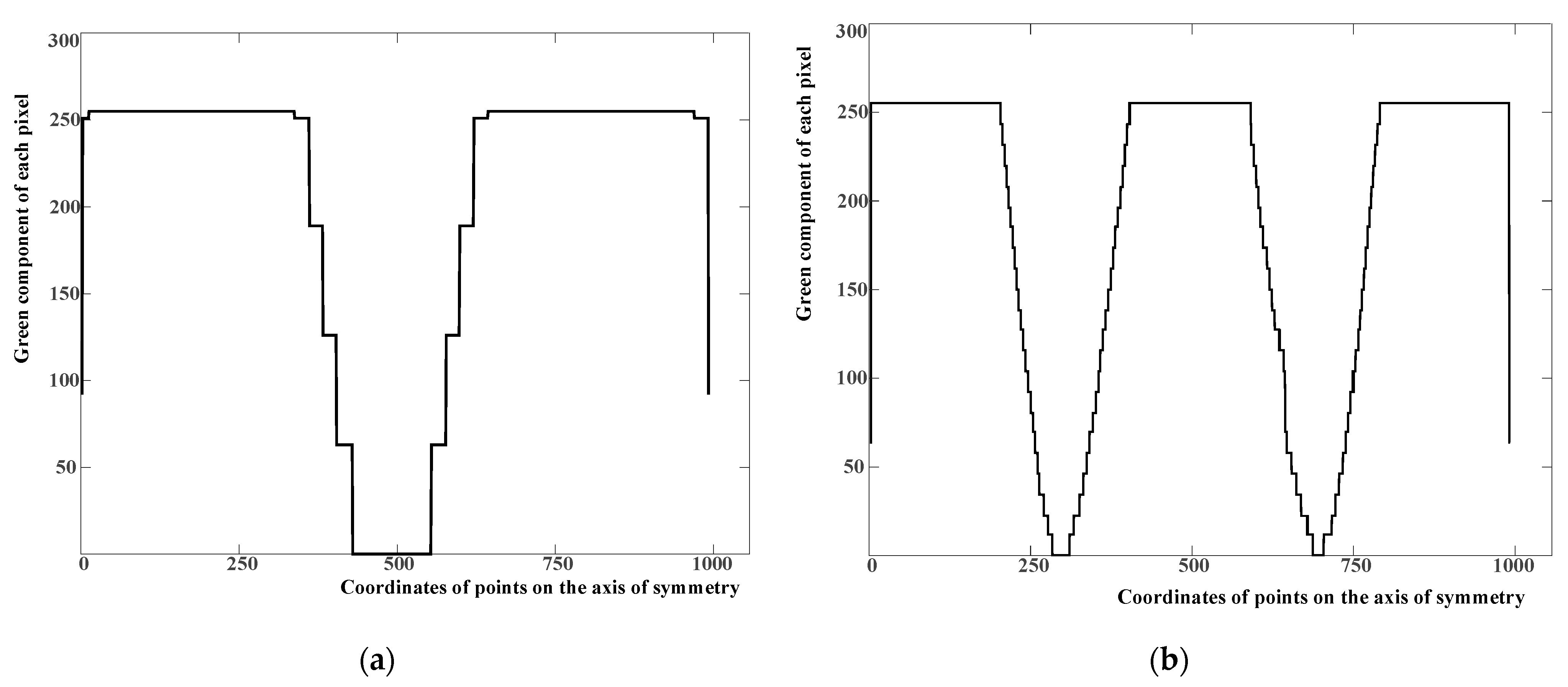
Analysis of the WPT system coil magnetic field cloud diagram obtained by FEM shows that the unipolar coil has a single magnetic field direction, while the bipolar coil has two opposite polarities in the plane perpendicular to the coil, which is reflected in the cloud diagram, it can be found that two areas of similar size but complementary colors appear on the symmetry axis along the Y-direction, which can be used as the basis for judging the polarity of the coil.
As for the magnetic field contours generated by different coils, there are obvious differences in intuitive perception, and the contour similarity S can be used as a basis for judging whether the contours of the two coils are similar.
The secondary coil identification algorithm of the wireless charging system based on the magnetic field cloud image features mainly compares and matches the unknown coil magnetic field cloud image with the known coil magnetic field cloud image to obtain the unknown coil type.
The main algorithm flow is as follows:
  • In the finite element software, simulate circular, square, DD, and solenoid coils of different sizes, and the coil size is fixed at 100 mm × 100 mm;
  • Choose a square plane with the same size as the coil at a certain height from the coil to obtain the magnetic field cloud image at that position;
  • Pre-process the coil magnetic field cloud image and down sample the image to 1024 × 1024 size;
  • Divide the obtained magnetic field cloud image into a test set and a template set according to the coil type;
  • Calculate the pixel value of the symmetrical axis along the Y direction of the unknown coil cloud image, and analyze the change of the pixel value on the axis, compare it with the template set, and determine whether it is unipolar or bipolar;
  • For unknown unipolar coils, the image segmentation algorithm is used to obtain the contours of different isomagnetic induction intensity lines, and the Hu invariant moments of the contours are calculated, and compared with the template set, it is judged whether it is a circular or a square coil;
  • For the unknown bipolar coil, the image segmentation algorithm is used to obtain the contours of the different isomagnetic induction intensity lines, the Hu invariant moment of the contour is calculated, and the shape template is compared to determine whether it is a DD coil or a spiral coil.
The following is the processing of the template set:
  • Image pre-processing;
  • Calculate the histogram of the corresponding coil;
  • Analyze the pixel value of the symmetry axis along the Y direction of the template set as the basis for determining the coil polarity;
  • Using the histogram back projection algorithm to obtain the contours of different isomagnetic induction intensity lines of the cloud image and save them to the contour vector;
  • Calculate the contour moments of different isomagnetic induction intensity lines and save them in the contour moment vector;
  • The algorithm flow chart is as shown in Figure 1.

4. Algorithm Verification and Analysis

4.1. Magnetic Field Acquisition

In the finite element software, different types of coils are calculated. We set the coils on the XOY plane, the diameter of the coil is 100 mm, the working frequency is 100 kHz, and the working current is 1 A. The magnetic field cloud images of different coils at different positions are obtained as shown in Figure 2. Figure 2a–d represent circular coils, square coils, DD coils, solenoid coils, and magnetic field cloud diagrams, respectively, at a distance of 15 mm from the coil.
The magnetic field shown in Figure 2 indicates that the circular coil and the square coil are unipolar coils, and the DD coil and the solenoid coil are bipolar coils. In the cloud diagrams, the red area and blue area represent high magnetic induction intensity in opposite directions. From the cloud diagram, we can intuitively see the law of the magnetic field passing through the plane. The magnetic field of the unipolar coil traverses once from the center of the plane. The magnetic field of the bipolar coil goes out from one side of the plane and then goes in from the other side. It appears that a unipolar coil cloud diagram has one center, the bipolar coil cloud diagram has two centers.
For different types of coils, under the premise of ensuring that the outer dimensions of the coils are consistent, the number of turns and the pitch of the coils are changed, and FEM calculation is carried out. A total of 32 coils are simulated. Among them, there are nine circular coils, nine square coils, nine DD coils, and four solenoid coils. The coil parameters are shown in Table 1.

4.2. Algorithm Verification

Some cloud images are randomly selected as the template set (No. 1, 4, 7, 12, 15, 18, 19, 21, 22, 28, 30), and the other cloud images are used as the test set, which are verified by the proposed algorithm.
The verification platform is based on the Ubuntu20.04 platform with the help of the image algorithm API provided by Opencv.
First, judge the polarity of the coil. Figure 3 shows the distribution of pixels on the symmetry axis of different coil cloud images. The abscissa represents the coordinates of each point on the symmetry axis, and the ordinate represents the value of the green component of each pixel on the symmetry axis. The green component of the unipolar coil has two flat top waves, and the green component of the bipolar coil has three flat top waves. Based on this, it can be determined whether the test coil is a bipolar coil or a unipolar coil.
Next, the contour of the test set coil is extracted and the similarity S between the contour moment value of the coil of the same polarity and the contour moment value of the template set coil is calculated.
Figure 4 is a schematic diagram of contour extraction. Based on the proposed algorithm, the contour of the magnetic field cloud image is drawn, and the disordered and incomplete contours at the edge of the cloud image is removed to obtain a more reasonable contour of the coil cloud image. Figure 4a–d shows the magnetic field cloud image of circular coil, square coil, DD coil, solenoid coil, respectively, with the contour of the extracted magnetic field cloud image.

4.3. Recognition Results

Table 2 shows the similarity S between the different coil contours obtained and the contour of the template set. Since the foregoing has already determined the polarity of the coil, the calculation and comparison of the similarity S can only be carried out between coils of the same polarity.
By calculating the contour moments in the cloud image, it is found that the Hu invariant moments of some contours in the same cloud image are similar. This is because the Hu invariant moments are scale-invariant. When there are contours with similar shapes but different sizes and positions, their Hu invariant moments also similar. By analyzing the similarity S between different coils’ Hu invariant moments according to Equations (15)–(17), it can be obtained that for a unipolar coil, when matched with a circular coil, the contour Hu invariant moment’s similarity S is within [0, 0.094080], which can be judged as a circular coil. When matched with a square coil, the similarity S of constant moment of the contour Hu is within [0, 0.097492], which can be judged as a square coil; For bipolar coils, when matched with DD-type coils, the similarity S of constant moment of contour Hu is within [0, 0.297330], which can be judged as DD-type coils. When matched with the solenoid coil, the similarity S of constant moment of the profile Hu is within [0, 0.173247], which can be judged as a solenoid coil.

5. Conclusions

This paper proposes a coil recognition algorithm of WPT system based on the characteristics of magnetic field cloud image. We analyzed the different magnetic field cloud images characteristics of different types of coils at different positions obtained by FEM, and proposes a secondary coil identification algorithm of the wireless charging system with the characteristics of the magnetic field cloud image. By analyzing the histogram information of the cloud image and the Hu profile moment of the contours of different magnetic induction intensity lines in the cloud image, the characteristics of various cloud images are obtained, and the characteristics of the unknown coil and the known coil cloud image are compared to obtain the coil type. Through this algorithm, we can distinguish the coil polarity through the changes of pixel value of the symmetrical axis along the Y direction of the unknown coil cloud image, and get the unknown coil type by judging the similarity of the contours from template sets and test sets. The recognition success rate of the test coil can reach 100%. This algorithm still has certain limitations. Firstly, the magnetic field cloud image is an image of a specific location and size. In actual operation, only the magnetic induction intensity value at some locations can be obtained; secondly, the current recognition method can only identify the unknown coil type, and cannot obtain the size, turns, distance, and other information of the unknown coil through the cloud image. In the follow-up, we will combine deep learning and other methods to gradually analyze the distribution law of the magnetic field cloud image when multiple coils form a coil network, realize the extraction of coil space magnetic field characteristics, establish coil space magnetic field models of different structure types with different coil parameters, and guide the matching scheme of the primary and secondary coils to achieve efficient energy transmission.

Author Contributions

F.W. conceived and designed the study, and this work was performed under the advice of and regular feedback from him. C.H. and Q.L. was responsible for the models, simulations and C.H. wrote the article. Z.C. and W.Z. was responsible for the experiments. S.W., X.Z. and W.P. was responsible for the data analysis. All authors have read and agreed to the published version of the manuscript.

Funding

This work was Funded by China Postdoctoral Science Foundation (2020M671498), the Basic Research Program of Jiangsu Province (BK20180485), the Fundamental Research Funds for the Central Universities (30919011241), the Jiangsu Planned Projects for Postdoctoral Research Funds (2020Z374), and the Science and Technology Project of State Grid Jiangsu Electric Power Co., Ltd. (J2020135, SGJSJX00BGJS2002373).

Institutional Review Board Statement

Not applicable.

Informed Consent Statement

Not applicable.

Conflicts of Interest

Feng Wen has received research grants from the Maintenance Branch Company, State Grid Jiangsu Electric Power Co., Ltd., (Science and Technology Project of State Grid Jiangsu Electric Power Co., Ltd., Grant No. J2020135, SGJSJX00BGJS2002373.). Zhoujian Chu and Wenhan Zhao are employees of the Maintenance Branch Company, State Grid Jiangsu Electric Power Co., Ltd. The paper reflects the views of the scientists, and not the company.

References

  1. Xue, M.; Yang, Q.; Zhang, P.; Guo, J.; Li, Y.; Zhang, X. Application Status and Key Issues of Wireless Power Transmission Technology. Trans. Chin. Soc. 2021, 36, 1547–1568. [Google Scholar]
  2. Chen, X.; Xu, K.; Mu, X.; Li, G. Comparisons of inductive coupling and ultrasonic coupling wireless power transfer under seawater. Electr. Mach. Control. 2018, 22, 9–16. [Google Scholar]
  3. Thenathayalan, D.; Lee, C.G.; Park, J.H. High-order resonant converter topology with extremely lowcoupling contactless transformers. IEEE Trans. Power Electron. 2016, 31, 2347–2361. [Google Scholar] [CrossRef]
  4. Liu, Z.; Chen, Z.; Li, J.; Zhao, H. A shapereconfigurable modularized wireless power transfer array system for multipurpose wireless charging applications. IEEE Trans. Antennas Propag. 2018, 66, 4252–4259. [Google Scholar] [CrossRef]
  5. Huang, Z.; Wang, L.; Zou, J. The influence of coil location parameters to load power in wireless power transmission with two or three relay coils. Trans. China Electrotech. Soc. 2017, 32, 208–214. [Google Scholar]
  6. Budhia, M.; Boys, J.T.; Covic, G.A.; Huang, C.Y. Development of a Single-Sided Flux Magnetic Coupler for Electric Vehicle IPT Charging Systems. IEEE Trans. Ind. Electron. 2013, 60, 318–328. [Google Scholar] [CrossRef]
  7. Bucolo, M.; Buscarino, A.; Famoso, C.; Fortuna, L. Control of imperfect dynamical systems. Nonlinear Dyn. 2019, 98, 2989–2999. [Google Scholar] [CrossRef]
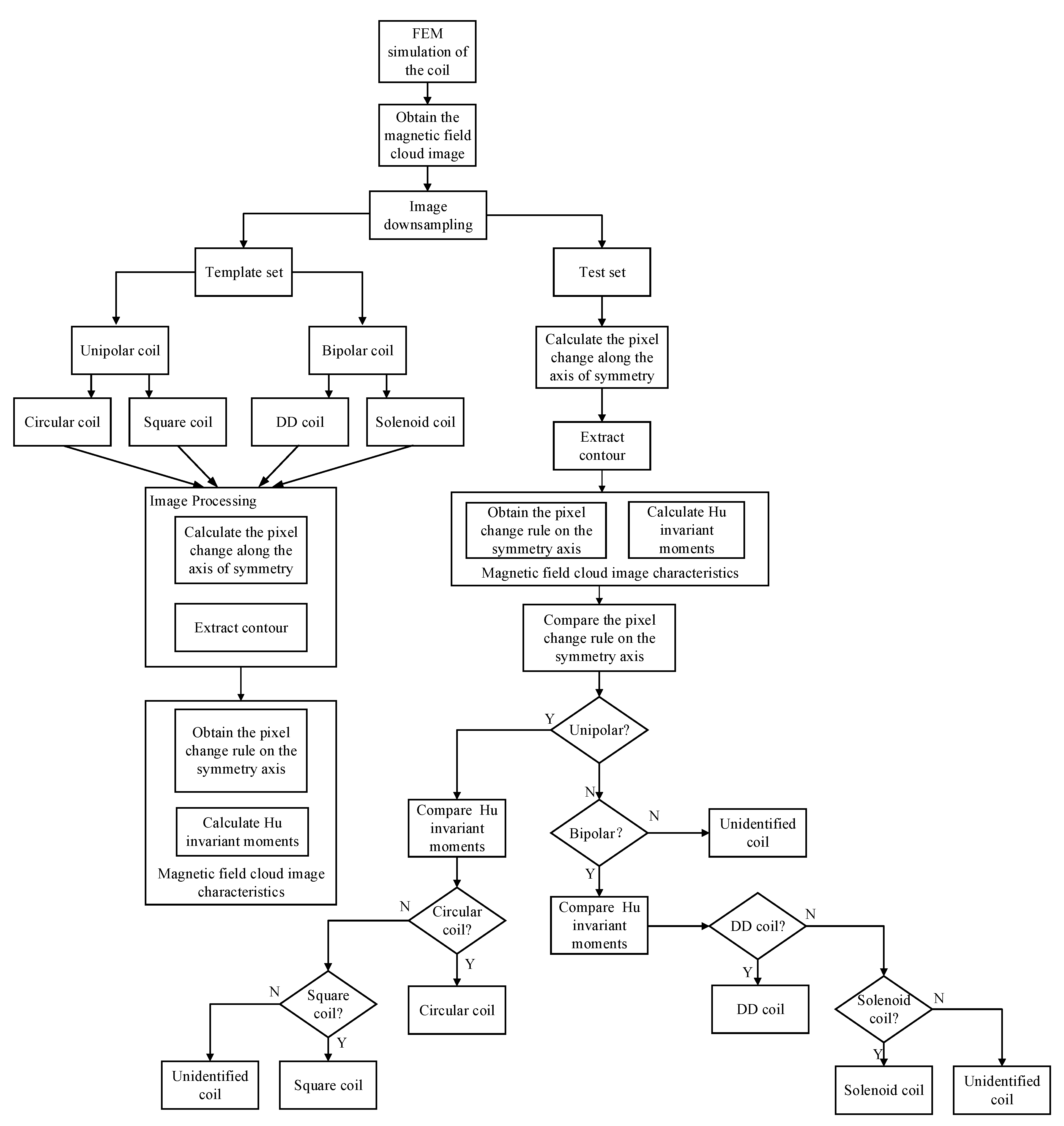
Figure 1. Coil identification algorithm flow.
Wevj 12 00140 g001
Figure 2. (a) Circular coil and magnetic field cloud diagram; (b) Square coil and magnetic field cloud diagram; (c) DD coil and magnetic field cloud diagram; (d) Solenoid coil and magnetic field cloud diagram.
Wevj 12 00140 g002
Figure 3. The distribution of the green component of each pixel on the symmetry axis of the coil magnetic field cloud image. (a) The distribution of the green component of each pixel on the symmetry axis of the unipolar coil magnetic field cloud image; (b) The distribution of the green component of each pixel on the symmetry axis of the bipolar coil magnetic field cloud image.
Wevj 12 00140 g003
Figure 4. The schematic diagram of contour extraction. (a) Circular coil magnetic field cloud with the contour; (b) Square coil magnetic field cloud with the contour; (c) DD coil magnetic field cloud with the contour; (d) Solenoid coil magnetic field cloud with the contour.
Wevj 12 00140 g004aWevj 12 00140 g004b
Table 1. Parameters of the coils.
Serial NumberCoil TypeTurnsTurn Pitch(mm)Serial NumberCoil TypeTurnsTurn Pitch(mm)
1Circular coil5219DD coil52
24204
36216
410222102
54234
66246
715225152
84264
96276
10Square coil5228Solenoid coil520
11429812.5
126301010
1310231205
14432254
156
16152
174
186
Table 2. The similarity S between different coils.
Serial NumberUnipolar CoilBipolar Coil
1471215181921222830
20.0787550.0348820.0606335.730088.9430410.3287
30.0203090.0855260.0844773.971954.9532712.3039
50.0730370.0906150.0175326.4707410.57953.13203
60.0787780.0392460.0503257.4610410.30538.45509
80.0448100.0940800.0695713.357934.7703911.4444
90.0787550.0348820.0606334.217951.5614011.0764
1010.409710.037071.532340.0814270.0121490.055514
114.787047.545726.213160.0476490.0367170.041636
1311.23363.597014.207370.0452780.0865200.097492
1410.54679.280335.396170.0356290.0849080.094661
169.668527.9163910.98290.0951360.0194690.097320
179.2753910.64968.304290.0928680.0825980.033442
20 0.1496700.1874800.1721201.076921.25219
23 0.1820400.1193100.1872701.025481.1752
24 0.2452000.1684800.2660101.338491.30521
25 0.1244700.1448200.1983301.325161.33542
26 0.2116300.1101900.1142701.212680.98731
27 0.1397200.1859300.2973301.12281.34073
29 1.007881.313171.052090.1395760.185053
30 1.101041.181951.178960.1732470.148102
31 0.972261.180111.128150.1036880.121645
Publisher’s Note: MDPI stays neutral with regard to jurisdictional claims in published maps and institutional affiliations.