1. Introduction
The global environmental and energy problems are becoming increasingly severe, and electric vehicles have obvious advantages in energy saving and emission reduction, so they are developing rapidly [
1,
2,
3,
4,
5]. With the large-scale development of electric vehicles, the construction of electric vehicle charging facilities has received strong support from governments around the world [
6,
7]. From 2015 to 2017, China has successively updated and issued seven national standards related to the technical conditions and test specifications of electric vehicle charging equipment [
8,
9]. The State Grid Corporation has also invested in the construction of charging piles and charging stations according to the national standards. [
10,
11]. According to statistics from the Charging Alliance, at the end of 2019, the number of charging piles in China has reached 1.219 million.
With the construction and operation of a large number of electric vehicle charging equipment, the issue of charging reliability and safety has gradually become the focus of attention. The operating state of the electric vehicle charging equipment will not only affect its own reliability, but will also affect the service life of the power battery [
12,
13,
14,
15]. The daily operation, maintenance and repair of the electric vehicle charging equipment cannot be ignored, but the fault monitoring during the charging process of the electric vehicle charging equipment is equally important. Gao et al. [
16] designed a mobile monitoring and fault diagnosis system for electric vehicle charging equipment, and used the fault tree method to analyze and diagnose the faults of the charging pile. The literature Xu et al. [
17] has proposed the detection technology of charging facilities and their application in the field, and classified and analyzed the common faults in the field detection. Another study Xiangwu et al. [
18] proposed a comprehensive evaluation method for the performance status of electric vehicle chargers. The fuzzy comprehensive evaluation theory was used to establish an evaluation model to achieve a comprehensive evaluation of the performance status of the charger. The literature Dandan et al. [
19] analyzes and introduces a fault diagnosis method for the fault where the charging port indicator does not light and does not charge after the pure electric vehicle is inserted into the charging gun. Reference Jing et al. [
20] takes the EV300 electric vehicle charging system as an example, and explores the diagnosis method of the charging gun insertion signal and charging conduction signal fault. The research of Chenxi et al. [
21] mainly studied the diagnosis methods of two failure phenomena, that is, when the car cannot be powered on and charged normally.
The above electric vehicle charging fault diagnosis method only focuses on discovering the possible faults of the charger, and does not monitor and warn about the possible faults of the battery management system during the charging process. In view of the shortcomings of current electric vehicle charging fault monitoring methods, this paper proposes an electric vehicle charging fault monitoring and early warning method based on the battery model, which can identify more than 10 types of faults including BMS (Battery Management System) function failure.
2. Technical Scheme of Charging Fault Monitoring and Early Warning Methods
The functional structure of the electric vehicle charging fault monitoring and early warning method based on the battery model is shown in
Figure 1. The central control unit builds a simulated battery model based on the battery parameters and the measured charging current or voltage and simulates the charging response of the actual battery. The model includes battery voltage, current, SOC (state of charge), temperature, and other information. The human–machine interface module displays the battery model charging status information and provides an interface for setting the battery parameters. The battery model parameters can be manually set according to the type, specifications, and parameters of electric vehicle power storage batteries, and can also intuitively monitor the battery charging status in real time. The measurement signal receiving module transmits the measured charging current or voltage to the battery model to simulate the charging response. The CAN (Controller Area Network) monitoring module is used to monitor the messages BCS (total battery charge status message), CCS (total charger charge status message) and BCL (battery charging demand message) during the communication between the off-board charger and the BMS. The central data processing unit analyzes the charging status message obtained by the CAN monitoring module, monitors the charging status of the electric vehicle and the battery charging demand, compares the battery charging response simulated by the battery model with the battery charging status information, and at the same time, compares the charging status information of the charger with the battery charging demand, in order to find charging faults in time and send out alarm prompts.
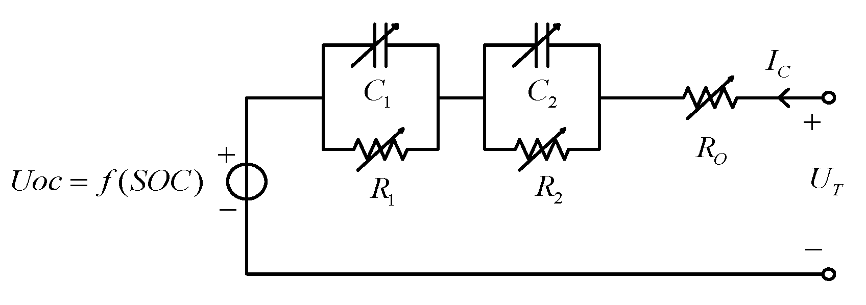
3. Single Power Battery Model
The structure of the single power cell model can be divided into two major parts: the open circuit voltage characteristics and the internal resistance characteristics of a cell [
22,
23,
24,
25]. The dynamic circuit model of a cell is shown in
Figure 2.
In
Figure 2, the
represents the internal ohmic resistance of cell, and
, and
represent the charging current and terminal voltage of a cell respectively. The parallel circuits consisting of
and
are used to describe the concentration polarization and electrochemical polarization of cell respectively.
4. Charging Response Simulation
The charging response simulation of a cell is that the charging response information of the cell such as voltage, current, SOC, and temperature are obtained through simulation calculation based on the measured charging output.
The expression of the SOC of the cell in the discrete time domain is:
where,
is the capacity of the single cell,
is the SOC influence coefficient,
is the temperature influence coefficient and
is the reference coulombic efficiency. It can be seen from
Figure 2 that the terminal voltage of the cell in the constant current mode is implemented using the following expressions:
where,
is the concentration polarization voltage of the single cell at discrete-time index(
),
is the electrochemical polarization voltage of the cell at discrete-time index(
),
is the concentration polarization voltage of the cell at discrete-time index(
),
is the electrochemical polarization voltage of the cell at discrete-time index(
),
is the open circuit voltage of the cell at discrete-time index(
), and
is the charging current. The internal polarization resistance
and
, internal ohmic resistance
and the polarization time constants
and
based on different SOC can be obtained by linear interpolation according to the parameter identification template data. In the constant voltage mode, the charging current is calculated as:
Here, is the charging voltage.
The cell temperature is calculated as follows:
where,
is the heat generation of a cell,
is the electrochemical reaction heat per unit,
is the heat dissipation of cell.
is the cell temperature,
is the ambient temperature, and
is the thermal resistance. The flow chart of the battery model simulation charging response calculation is shown in
Figure 3. The
is the battery terminal voltage.
represents the battery terminal voltage in the constant voltage charging mode, and
represents the battery current in the constant current charging mode.
5. Battery Model Verification
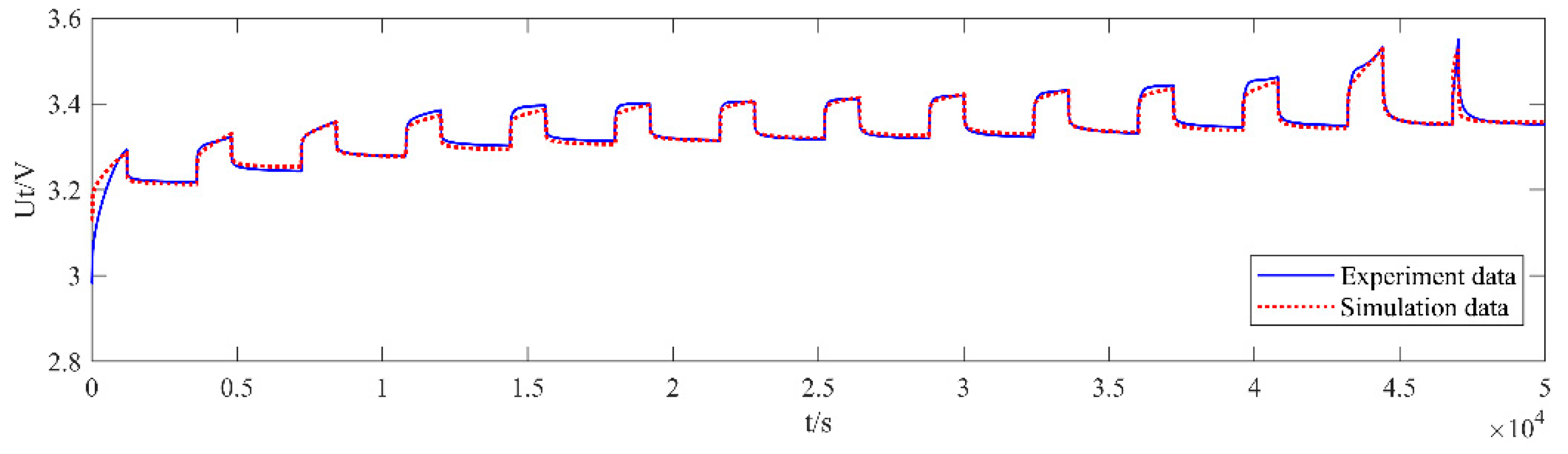
The LiFePO4 battery was used for the charging experiment, and compared with the charging simulation results of the battery model to verify the correctness and effectiveness of the battery model. At the laboratory temperature 20~25 °C, the actual LiFePO4 battery pack was charged in the mode of intermittent current which is 5 A, 10 A, and 20 A respectively and the mode of “constant current 5 A-constant voltage 350 V”. The experimental results and the battery model simulation results are shown in
Figure 4,
Figure 5,
Figure 6 and
Figure 7, respectively.
Through the comparison of the experimental results, it can be seen that the battery model proposed in this paper can well simulate the charging characteristics of the actual battery. The maximum voltage error does not exceed 0.05 V, and the maximum current error does not exceed 0.5 A, which can meet the needs of electric vehicle charging fault monitoring.
6. Failure Monitoring Methods
6.1. CAN Bus Monitoring
CAN bus is a serial communication bus that uses twisted pair differential signals to transmit information. It supports multiple device units to share a set of data. The units connected to the bus have the same status regardless of the master and slave. When the bus is idle, the bus level can be changed by controlling the potential difference between the two signal wires to achieve the purpose of information transmission. At the same time, each equipment unit can share CAN bus information, and obtain the data they need through frame ID identification. During the charging process, the charging facility and the battery management system can be regarded as a device unit respectively, and the two will transmit charging status data on the CAN bus. If an independent CAN device unit is designed to connect to the CAN bus of the two communication, you can monitor the communication data on the CAN bus.
This article uses the USBCAN-2I interface card as a CAN communication node to connect to the CAN communication network of the off-board charger and battery management system. The CAN communication node serves as a third-party CAN monitoring unit, which only receives and analyzes the communication messages sent between the charger and management systems according to the communication protocol during the charging communication process.
A complete charging process includes low-voltage auxiliary power-on and handshake stage, parameter configuration stage, charging stage and charging end stage. When an abnormal situation such as communication timeout or communication interruption occurs in any stage, the charging facility should immediately stop the output, end the charging process, and restart the charging after the related fault is eliminated. During the normal process of each of the above stages, the charging facilities and the battery management system will send iconic communication messages to each other through the CAN bus. The message process of each stage is shown in
Figure 8.
Refer to
Table 1 for the content of each message code.
Each valid communication data unit between the electric vehicle charger and the battery management system acquired by the USBCAN-2I interface card on the bus includes 29-bit frame ID information and 64-bit data information. Each frame ID includes priority information (P), reserved bits (R), data page (DP), parameter number (PF) and address information (PS, SA).
When the communication message carries more than eight bytes of data information, this kind of message implements the transmission function of multiple packets of the same message through the transmission protocol in accordance with the relevant regulations of SAEJ1939-21:2006. The transmission protocol mainly includes four parts: multi-packet sending request (TCPM-RTS), multi-packet sending request response (TCPM-CTS), multi-packet data transmission (TCPM-DT), and receiving completion response (TCPM-EM). The PF bits in the class message frame ID are both EC (H) and EB (H), so the message type cannot be directly determined by the PF bit. At this time, the communication needs to be based on the PF bit in the message frame ID as EC (H). The penultimate byte of the data field carried by the data unit is used to determine the message type.
The flowchart of the message parsing program designed according to the message parsing rules is shown in
Figure 9. After reading the ID frame of the communication data unit, the program first determines whether the PF bit of the ID frame is EC (H), if not, it can directly determine the message type by the value of the PF bit, and then analyze the data frame according to the message type; If so, you need to read the data frame of the corresponding data unit, judge the message type through the seventh byte of the data frame, and then read the next data unit information, when it is recognized that the PF bit of the ID frame becomes EB (H), read the data frame of the current data unit, and analyze data according to the message type information transmitted by the previous data unit.
6.2. Implementation of Fault Monitoring Methods
Construct a power battery model according to the type, specification and parameter information of the electric vehicle power battery, such as battery type, rated capacity, initial state of charge and other information, and the battery model calculates and simulates the charging response of the power battery. In the third stage (charging stage) of the charging communication process between the electric vehicle charger and the battery management system, the BMS sends a battery charge request message (BCL) and a battery charge status message (BCS) to the charger, and the charger sends The BMS sends the charging status message (CCS) of the charger. The BCL message information sent by the BMS is shown in
Table 2, the BCS message information is shown in
Table 3, and the CCS message information sent by the charger is shown in
Table 4.
A power battery model is constructed based on the type, specifications, and parameter information of the electric vehicle power battery, such as battery type, rated capacity, initial state of charge, etc. The battery model calculates and simulates the power battery charging response. In the third stage (charging stage) of the charging communication process between the electric vehicle charger and the battery management system, the BMS sends a battery charging demand message (BCL) and a battery charge total status message (BCS) to the charger. The BMS sends the charging status message (CCS) of the charger.
Use CAN bus monitoring technology to analyze the CAN communication messages of the charger and battery management system during the charging process, obtain the charger and battery charging status information and battery charging demand information in real time. Compare the charging response information simulated by the battery model with the charging state information of the battery, and at the same time compare the charging state information of the charger with the battery charging demand information to determine whether the charging process is normal. If the difference of the comparison information is within the allowable range, it means that the charging process is normal, if there is a significant difference in the comparison information, it means that the charging process is wrong. The specific analysis of the difference information can clarify the charging failure information, and then realize the charging failure warning. The flowchart of the implementation method of the fault monitoring method is shown in
Figure 10.
6.3. Verification of Fault Monitoring Methods
Using the charging data provided by a charging pile monitoring platform (including charging accident records), the proposed electric vehicle charging fault monitoring method based on battery model is verified
6.3.1. Normal Charging Process
Select a complete set of battery status information data during the normal charging process of electric vehicles, including charging time, charging current, charging voltage, state of charge and other information. Design a program in the MATLAB simulation environment to verify the proposed fault monitoring method feasibility. The comparison result between the SOC calculation data of the battery model and the SOC data provided by BMS is shown in
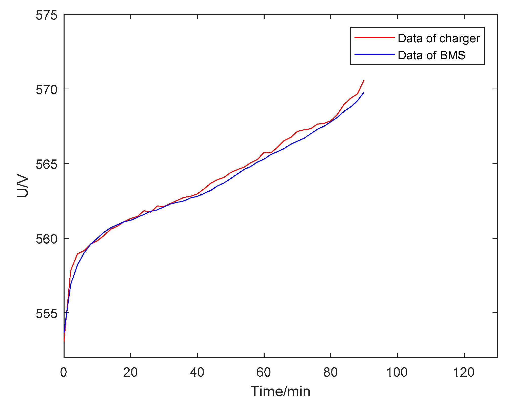
Figure 11, and the maximum relative error between the calculation data of the battery model and the data provided by BMS is less than 2%. The comparison result between the voltage calculation data of the battery model and the voltage data provided by the BMS is shown in
Figure 12, and the maximum relative error between the calculation data of the battery model and the data provided by the BMS is less than 0.5%. The above comparison results show that the charging process of electric vehicles is normal. The charging results show that the initial SOC of the battery is 60%, the initial voltage is 552 V, the battery is fully charged in 92 min, and the voltage reaches 570 V.
6.3.2. Abnormal Charging Process
The charging data of electric vehicles in charging accident cases are selected to verify the application of the proposed fault monitoring method in the abnormal charging process. The comparison between the SOC calculation data of the battery model and the SOC data provided by BMS is shown in
Figure 13. As can be seen from
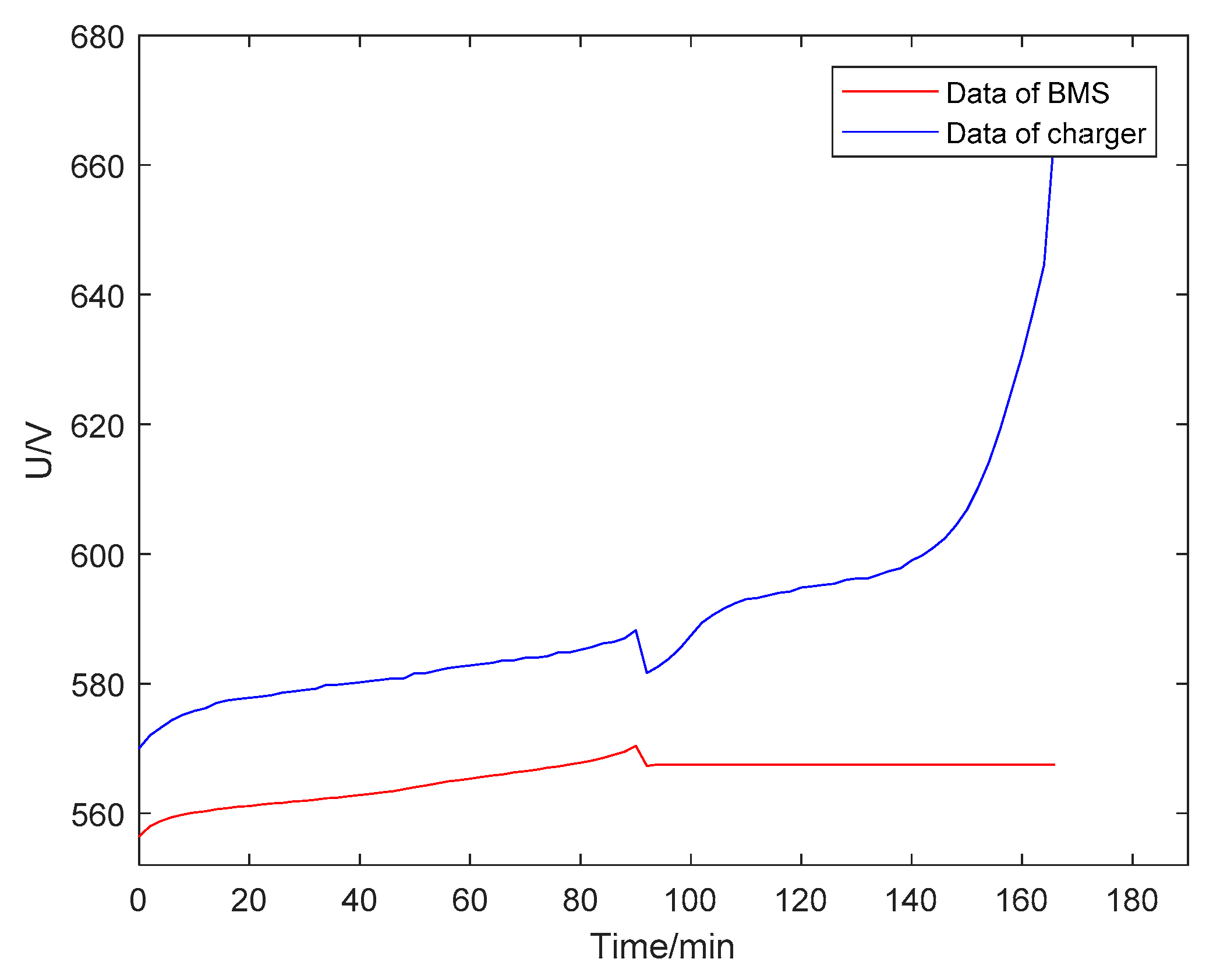
Figure 13, the initial SOC of the battery is 62%. When the battery has been fully charged for 88 min, BMS did not send a charge stop instruction to the charger, the battery continued to charge. Under normal circumstances, the charging process should be stopped. Therefore, there is an abnormality in the charging process and a warning signal for charging failure should be issued. The comparison between the charging voltage information provided by the charger and the charging voltage data provided by BMS is shown in
Figure 14, and it can be seen from
Figure 14 that when the battery is fully charged for 88 min, the charging process continues, and the battery voltage data provided by BMS is not updated according to the actual charging process, there is a big difference between the battery charging demand and the charging voltage of the charger. The difference value exceeds the allowable range. It can be judged that the charging process is abnormal or faulty due to the failure of the BMS module function. However, due to the lack of an active protection mechanism, the charger failed to issue a warning signal in time, and failed to stop the charging process in time.
7. Results and Discussions
The on-site monitoring method for charging faults of electric vehicles based on the battery model mentioned in this paper can effectively find the types of faults that may occur during the charging process.
Table 5 lists the identifiable fault types and fault discrimination methods.
- (1)
BMS and charger communication failure
The failure of BMS communication can be judged by analyzing whether the communication messages sent by the BMS in the four stages of the charging process comply with the regulations of the communication protocol. When the BMS communication function is normal, the corresponding messages will be sent according to the regulations of the communication protocol. When abnormal conditions such as communication timeout, communication error, communication interruption occur at any stage of the process, which is regarded as the failure of the BMS communication function. The communication failure of the charger can be judged by analyzing whether the communication messages sent by the charger during the four stages of the charging process comply with the provisions of the communication protocol. When the communication function of the charger is normal, the corresponding messages will be sent according to the provisions of the communication protocol. When the charger has communication timeout, communication error, communication interruption and other abnormal conditions at any stage of the charging process, which will be regarded as the charger’s communication function failure.
- (2)
BMS voltage and current detection fails, and SOC estimation is inaccurate
Analyze the battery charge status message (BCS) and compare the charging voltage with the calculation result of the battery model. When the difference exceeds the allowable range of voltage deviation, which can be judged that the BMS voltage detection failure has occurred; compare the charging current with the calculation result of the battery model. If the difference exceeds the allowable range of current deviation, which can be judged that the BMS current detection fails; compare the battery SOC with the calculation result of the battery model SOC, when the difference exceeds the allowable range of SOC deviation, which can be judged that the SOC estimation is inaccurate.
- (3)
BMS motherboard failure
When the BMS communication fails, the BMS should send a charging stop request to stop the charging process in time. If the BMS main board fails, the charging process cannot be stopped in time. The BMS main board failure can be judged by monitoring the charging process after the abnormal charging occurs.
- (4)
The output voltage of the charger is too high or too low
Analyze the battery charging request message (BCL) and the charger charging status message (CCS), compare the charger output voltage with the battery charging voltage demand, if the charger output voltage is greater than the allowable range, it means that the charger output voltage is too high. If the output voltage of the charger is less than the allowable range, it means that the output voltage of the charger is too low.
- (5)
The output current of the charger is too large or too small
Analyze the battery charge request message (BCL) and the charger charge status message (CCS), compare the charger output current with the battery charging current demand, if the charger output current is greater than the allowable range, it means that the charger output current is too large. If the charger output current is less than the allowable range, it means that the charger output current is too small.
8. Conclusions
This paper presents a method for the monitoring and early warning of electric vehicle charging faults based on a battery model. A second-order dynamic circuit model of the power battery is proposed to simulate the charging characteristics of the battery. The battery model is experimentally verified with a lithium iron phosphate battery as an example. The results show that the proposed battery model can correctly simulate the charging response of different types, specifications and parameters of power batteries. The voltage error does not exceed 0.05 V, and the maximum current error does not exceed 0.5 A, which meets the needs of electric vehicle charging fault monitoring. Use CAN bus monitoring technology to receive and analyze charger charging information, battery charging information and battery charging demand information. Compare the charge response information simulated by the battery model with the charge status information of the battery, and compare the charge status information of the charger with the battery charging demand information to determine whether the charging process is normal. When an abnormal charging situation is judged, an early warning fault sign will be issued in time. The charging data (including charging accident data) provided by a charging pile monitoring platform was used to verify the feasibility of the fault monitoring method under normal and abnormal charging conditions. This method can identify more than 10 types of faults. According to the types of faults, they can be summarized into 5 types of faults, including BMS and charger communication failure, and provide fault verification data.


