Article

Performances Analysis of a Novel Electromagnetic-Frictional Integrated Brake Based on Multi-Physical Fields Coupling

1
School of Automotive and Traffic Engineering, Jiangsu University, Zhenjiang 212013, China
2
School of Automotive and Traffic Engineering, Jiangsu University of Technology, Changzhou 213001, China
*
Author to whom correspondence should be addressed.
World Electr. Veh. J. 2019, 10(1), 9; https://doi.org/10.3390/wevj10010009
Submission received: 25 December 2018 / Revised: 15 February 2019 / Accepted: 19 February 2019 / Published: 21 February 2019

Abstract

:
In this article, a novel electromagnetic-frictional integrated brake is proposed, and its structure and working principle are introduced. The geometric model and mathematical models of integrated brake were established, and the multi-field coupling mechanism of integrated brake were analyzed. With BYD Qin as a reference vehicle, the boundary conditions of thermal load and force load of integrated brake were determined according to its structure and performance parameters. Based on the COMSOL software, numerical coupling calculations of electric, magnetic, thermal, and solid fields of integrated brake were carried out respectively in the emergency and downhill braking at a constant speed. The axial, circumferential, and radial temperature distributions of integrated brake disc were analyzed respectively, and they were compared with those of the traditional friction brake disc. The analysis results show that the proposed integrated brake can effectively improve the heat fading resistance of automotive brake during emergency and continuous braking. Under the two braking conditions, the temperature rise of friction brake was faster than that of an electromagnetic brake, and the effect of the electromagnetic brake on temperature rise of integrated brake was small.

1. Introduction

As we all know, the brake is one of the main components of vehicle chassis, which has important influence on driving safety and braking performances. At present, friction braking is still the main form of vehicle braking, which changes the kinetic and potential energies of a vehicle into heat energy by friction when braking. Braking energy dissipation will result in a significant increase in brake temperature, which may lead to brake heat fading [1]. Eddy current brake, which is considered to be a good complement to the traditional friction brake, has some potential advantages, i.e., contactless braking, reduced sensitivity to fading, faster dynamic response, and easier integration with other control systems. However, it alone cannot completely stop the vehicle, and it will consume some electrical energy when it works [2]. Therefore, in recent years, the integrated brake with friction braking and eddy current braking has been attracting increasing attention.
A novel integrated brake with friction braking and permanent magnet braking was proposed for automotive application, and the basic theoretical analysis, numerical simulation, and experimental verification on the integrated brake were carried out, which lay the foundation for subsequent research on the electromagnetic-frictional integrated brake [3]. The calculation formulas of braking torque for the electromagnetic-frictional integrated brake were obtained by an approximate theoretical model, and a sliding mode controller was designed for the integrated brake [4]. A three dimensional finite element analysis method was applied to the eddy current brake, and the effects of design parameters on the speed-torque characteristic curve of eddy current brake were analyzed [5]. A new layout structure with friction braking on front wheels and eddy current braking on rear wheels was proposed. Meanwhile, an anti-lock braking algorithm for eddy current brake was developed based on a nonlinear sliding mode controller [6]. The optimal design method was adopted to improve the braking torque of a vehicle, and the influence of structural parameters of integrated brake on braking moment were analyzed [7]. Based on the theory of multi-objective optimization, the performance indexes and geometric constraints, which must be met in the design process of integrated brake, were analyzed. A multi-objective optimization mathematical model, with maximum braking moment and minimum braking temperature rise as objective functions, was established [8]. According to the working state of integrated braking systems, the thermal and mechanical coupling analysis of the electro-mechanical brake was carried out. The thermal decay performance of integrated brake was verified by simulation. However, the effect of electromagnetic and thermal coupling on the composite brake was not considered [9]. The temperature distributions of integrated brake were calculated, respectively, when the electromagnetic brake worked alone and the electromagnetic brake was combined with the friction brake at the same time. However, the calculation method adopted has big error [10]. Based on a novel frictional-magnetic compound brake, the influential law of magnetic field on braking performance was investigated, and the influential mechanism of excitation voltage on braking performance was analyzed using bench tests [11].
The electromagnetic-frictional integrated brake is affected by the multi-physical fields coupling of electric field, magnetic field, structure, and thermal field, which have important influence on the parameter design and performance analysis of integrated brake. However, it can be seen that research on the integrated brake with friction braking and eddy current braking mainly focus on structural design, mathematical models, control strategies, and experimental analysis, as detailed in the above references. The study of physical fields of integrated brake is limited to the sequential coupling of two physical fields. The simultaneous action and coupling of multiple physical fields are rarely considered.
This paper will be organized as follows. In the Section 2, the structure and working modes of a novel electromagnetic-frictional integrated brake are introduced. In the Section 3, the multi-field coupling mechanism of electric field, magnetic field, structure, and thermal field of integrated brake is analyzed, and the mathematical models of integrated brake are established. In the Section 4, the three-dimensional model and the finite element model of integrated brake are established. In Section 5, the multi-field coupling simulation and analysis on the integrated brake are carried out under emergency braking and downhill continuous braking based on COMSOL software, and the effectiveness of integrated brake for thermal decay resistance is obtained. In the Section 6, some conclusions and the future work are presented briefly.

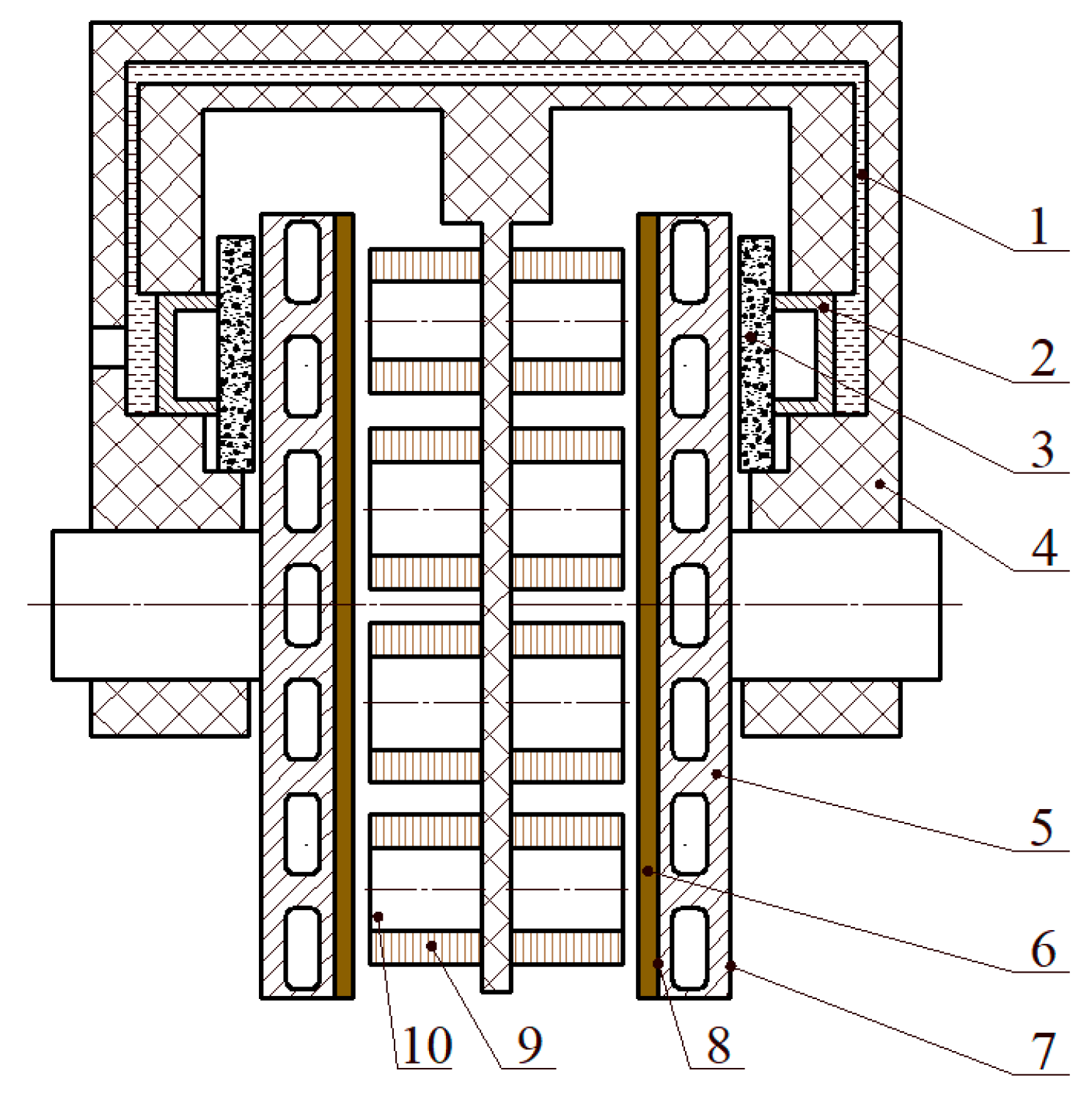
2. Structure and Working Modes

The simplified structure of a novel electromagnetic-frictional integrated brake is shown in Figure 1, which integrates friction brake and electromagnetic brake. The friction brake is similar to the traditional friction brake, which is mainly composed of the integrated brake disc, brake pads and caliper body. The electromagnetic brake is located inside the integrated brake disc, which is mainly composed of the integrated brake disc, iron cores, and coils. The friction brake transforms the braking energy of a vehicle into the heat energy of a brake to realize vehicle braking through friction between the brake disc and brake pads. The electromagnetic brake is a non-contact brake. When the current is in the coils, the magnetic field is generated around the coils. The rotating integrated brake disc cuts the magnetic force lines of coils, thus the eddy currents occur on the electromagnetic surfaces of the integrated brake disc. Under the action of eddy currents, the braking torque will be produced on the integrated brake disc, which will hinder the rotation of integrated brake disc and realize vehicle braking [3].
The electromagnetic-frictional integrated brake has three kinds of braking modes: pure friction braking, pure electromagnetic braking, and compound braking with both of them. When the integrated brake works, the driver’s braking intention is identified by the controller according to the travel signals from the brake pedal, vehicle speed signal, wheel speed signal, etc. According to the braking intention, different working modes will be adopted. For example, when the vehicle speed is high and the braking strength is low, the pure electromagnetic braking mode will be used to shorten the braking response time and reduce the brake pad wear. When the vehicle speed is high and the braking strength is high, the compound braking mode will be adopted to reduce the braking time of vehicle and improve the heat recession resistance of brake. When the vehicle speed is low (generally less than 20 km/h), the braking torque generated by electromagnetic brake is very small, so the pure friction braking mode will be adopted.

3. Mathematical Models of Multi-Field Coupling

3.1. Multi-Field Coupling Mechanism of the Integrated Brake

When the electromagnetic-frictional integrated brake works, a high-intensity magnetic field is generated by the coils with current, which generates eddy currents on the copper layers of electromagnetic brake surfaces. Therefore, there is coupling between the electric field and the magnetic field in the integrated brake. When the eddy current interacts with the magnetic field generated by the coils, the braking moment hindering the rotation of integrated brake disc will be produced, and there will be a coupling between the magnetic and stress fields. Eddy currents produce Joule heat in the integrated brake disc, which increase the temperature of integrated brake disc, change the electromagnetic performance parameters of the brake pads’ materials, and affect the eddy current field of the electromagnetic brake surface, thus leading to coupling between the electromagnetic field and the temperature field. In addition, the brake pads’ contact with the friction brake surfaces of the integrated brake disc under braking pressure, cause the braking pressure to form stress fields on the friction brake surfaces. The heat, which is generated by the friction between the rotating friction brake surfaces and the brake pads, is applied on the friction brake surfaces, which causes thermal deformation of the integrated brake disc. Therefore, there is a coupling between the temperature and stress fields. Briefly, the electromagnetic-frictional integrated brake is a complex device involving the coupling of multiple physical fields.

3.2. Multi-Field Coupling Mathematical Models of the Integrated Brake

When the integrated brake works, temperature rise of the integrated brake disc mainly consists of two parts: the friction heating part, and the electromagnetic heating part. The friction heating part comes from friction between the friction brake surfaces and brake pads, which flows freely into the integrated brake disc in the form of heat flow, and increases the integrated brake disc’s temperature. The electromagnetic heating part is caused by eddy currents generated on the electromagnetic brake’s surfaces. The Joule heat generated by the induced eddy currents is diffused to the integrated brake disc, which makes the integrated brake disc’s temperature rise. According to the different generation principles of friction heat and electromagnetic heat, using the energy conservation law and heat transfer principle, the differential equations of transient temperature field variable T(x, y, z) in the integrated brake disc are as follows in the rectangular coordinate system [12].
{ k x T x n x + k y T y n y + k z T z n z = q k x 2 T x 2 + k y 2 T y 2 + k z 2 T z 2 + q v = ρ m c T t
where ρm is the density of materials (kg/m3); c is the specific heat capacity of materials (J/(kg·K)); t is the time (s); kx, ky, and kz are the convective heat transfer coefficients of materials in the direction of x, y, and z, respectively (W/(m·K)); nx, ny, and nz are the cosines of the corresponding boundaries in the normal direction; q is the flux density of friction heat (W/m2); and qv is the intensity of internal heat source (W/m3).

3.3. Multi-Field Coupling Boundary Conditions for the Integrated Brake

In this paper, BYD Qin was selected as the reference vehicle, and some vehicle parameters are shown in Table 1.
(1) Thermal Load Calculation for the Integrated Brake Disc
The heat generated by friction braking flows into the integrated brake disc as the integrated brake disc rotates. The heat source moves relative to the integrated brake disc. The heat flux acting on the radial position r of the integrated brake disc is as follows [13]:
q ( r , t ) = η μ p ω 0 ( 1 t t s ) r
where q(r, t) is the heat flux produced by friction (W·m2), η is the efficiency of converting friction power into heat energy, μ is the friction factor, p is the brake specific pressure (N·m2), ω0 is the initial angular velocity, ts is the braking time (s), and r is the friction radius (mm).
When the electromagnetic brake is applied, eddy currents are generated on the electromagnetic brake surfaces. The governing equations can be expressed as follows [14]:
{ × ( 1 μ × A ) ( 1 μ A ) + σ ( A t + φ ) = 0 [ ( A t + φ ) ] = 0 J e = σ ( A t + φ )
where is the Hamilton operator, A is the vector magnetic potential, φ is the electric scalar potential, σ is the conductance potential of medium (s/m), μ is the magnetic conductivity of medium (H/m), and J e is the eddy density (W/m2).
The Joule heat generated by the eddy currents on the integrated brake disc is regarded as lots of tiny internal heat source blocks, which are used as temperature field load for the integrated brake disc during electromagnetic braking. After obtaining the eddy current density on the integrated brake disc, the generation rate of internal heat is derived from Joule’s law as follows:
q v = ρ | J e | 2
where ρ is the resistivity of materials of electromagnetic brake surfaces (Ω·m).
(2) Heat Convection of Integrated Brake Disc
During the braking process of the electromagnetic-frictional integrated brake, the temperature of integrated brake disc rises, and the convective heat exchange occurs between the integrated brake disc and the surrounding environment. It can be expressed as follows [15]:
T n = h ( T 1 T 2 )
In the above formula,
h = 0.037 D R e 0.8 P r 0.33 = 0.037 D ( p D v μ ) 0.8 ( C p μ k ) 0.33
where h is the coefficient of convective heat, T1 and T2 are the surface temperature and ambient temperature of integrated brake disc, respectively (°C), Re is the Reynolds number, Pr is the Prandtl number, μ is the viscosity coefficient of air, D is the diameter of integrated brake disc, ρ is the air density, Cp is the specific heat capacity of air, and k is the thermal conductivity of air.
(3) Heat Radiation of Integrated Brake Disc
During the working process of the integrated brake disc, it also exchanges heat with the environment by means of thermal radiation. The heat exchanged can be calculated by the Stephen–Boltzmann equation, which is shown below [15].
T n = ε σ A ( T 1 4 T 2 4 )
where ε is the radiation rate of materials in the vacuum condition, A is the shape coefficient of the radiation surface, which is not more than 1, and σ is the Stephen–Boltman constant which is generally taken as 5.67 × 10⁻⁸ W/(m2·°C4).
(4) Determining the Braking Load
Assuming that the vehicle runs on the road with peak adhesion coefficient and brakes, the front and rear wheels are locked, then the maximum normal acting force Fz2max of the rear axle is as follows:
F z 2 max = m g L ( a φ p h g )
where φp is the peak value of the adhesion coefficient, which is taken as 0.8 in this paper.
Assuming that the wheel loads are equal on both sides, the maximum braking force Pmax of a single rear wheel is as follows:
P max = ( F z 2 max / 2 ) φ p
In order to ensure that the wheels don’t lock when braking, the maximum braking moment Mmax of the integrated brake is limited to:
M max = P max R b
where Rb is the radius of tire.
The equation of braking moment may be obtained from reference [16]:
M R ( t ) = M max ( 1 e β t )
where MR(t) is the maximum friction moment (N·m), β is a parameter related to the structure of the integrated brake, and t is the braking time (s).
There are two brake pads on both sides of the integrated brake. For a single brake pad, the braking moment is as follows:
1 2 M R ( t ) = A μ P ( t ) r d A
In the above formula,
P ( t ) = M R ( t ) 2 μ A r d A = M R ( t ) 2 μ α 1 α 2 d a r 1 r 2 r 2 d r
where P(t) is the braking pressure generated by the brake piston (Pa), μ is the friction coefficient between the integrated brake disc and the brake pads which is taken as 0.35, α is the wrap angle of the brake pad (º), A is the area of brake pad (mm2), and r is the radius of brake pad (mm).

4. Establishing the Finite Element Model

4.1. Three-Dimensional Modeling of the Integrated Brake

The integrated brake is symmetrical left and right, thus only one half of the integrated brake is required for the simplicity of analysis. In this paper, the modeling function of the COMSOL software was directly used. The model does not need to be transformed. The information of the model is accurately retained, which is convenient for revision and parametric design. The three-dimensional model of the integrated brake is established, as shown in Figure 2.

4.2. Material Properties of Integrated Brake

Copper layers of the electromagnetic brake surfaces and the electromagnetic coils are made of copper, and the integrated brake disc is made of gray iron. The conductivity, relative dielectric constant and relative permeability of the related materials are shown in Table 2.

4.3. Adding the Required Physical Fields

The required physical fields are added based on the COMSOL software. The magnetic and electric fields were selected in the AC/DC module, and the number of coil turns was set to 256, coil conductivity was set to 6 × 10⁷ s/m, the diameter of coil wire was set to 1.5 mm, and the coils’ excitation current was set to 15 A. The physical field of solid heat transfer was selected in the heat transfer module, where some parameters, such as the velocity of translation motion, the initial value of temperature, the heat flux, the thermal contact, and the diffuse radiation coefficient, were set. The physical field of solid mechanics was added in the structural mechanics module, where the parameters of linear elastic material, freedom and initial value were set. In the mathematical module, the global ordinary differential equations and the differential-algebraic system of equations were selected, where the global equations for angular velocity were set. When calculating multi-physical fields, the four physical fields were simultaneously used as coupling interfaces to calculate the corresponding variables.

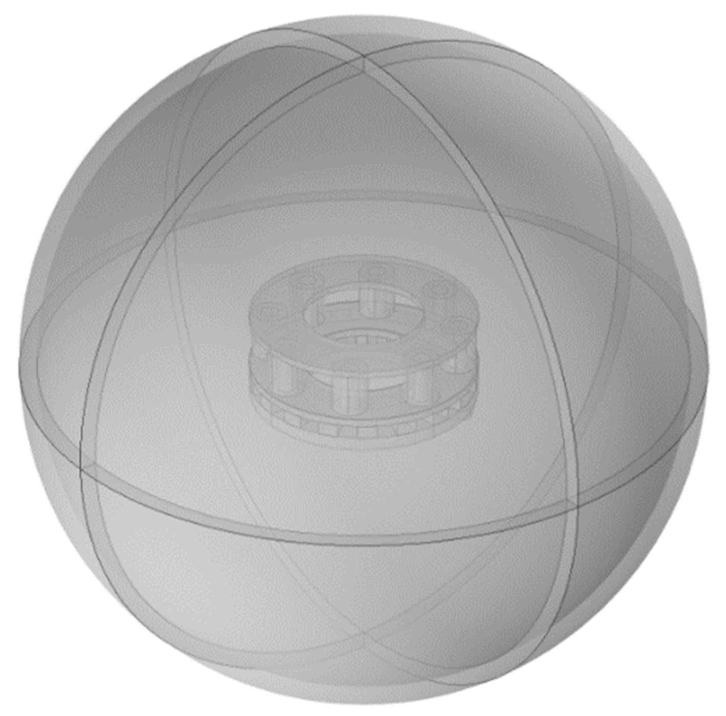
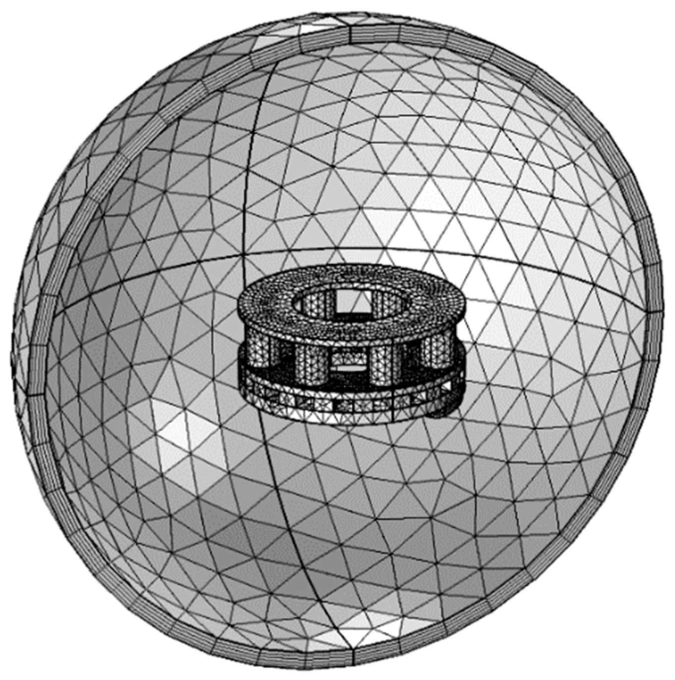
4.4. Computational Domain and Mesh Generation

The air gaps of electromagnetic brake have an effect on the working performance of integrated brake, and the integrated brake radiates heat to the surrounding air when it works, therefore, the calculated air area was set as a sphere enclosing the integrated brake model. The diameter of the sphere was three times that of the outer diameter of the integrated brake disc, as shown in Figure 3.
There are two types of mesh generation in the COMSOL software: free tetrahedral mesh generation and free triangular mesh generation. The structure of integrated brake is relatively complex, the tetrahedral mesh is relatively good for its adaptability, making it easy to capture geometric figures, the method of free tetrahedral mesh generation was adopted in this paper. The copper layers of electromagnetic brake surfaces adopt the comparatively refined grid, the other surfaces of integrated brake adopt refined grid density, and conventional grid density was used in the computational domain. The divided mesh consists of 87,049 domain elements and 1797 boundary elements. The calculation model of the integrated brake after meshing is shown in Figure 4.

5. Numerical Simulation and Analysis

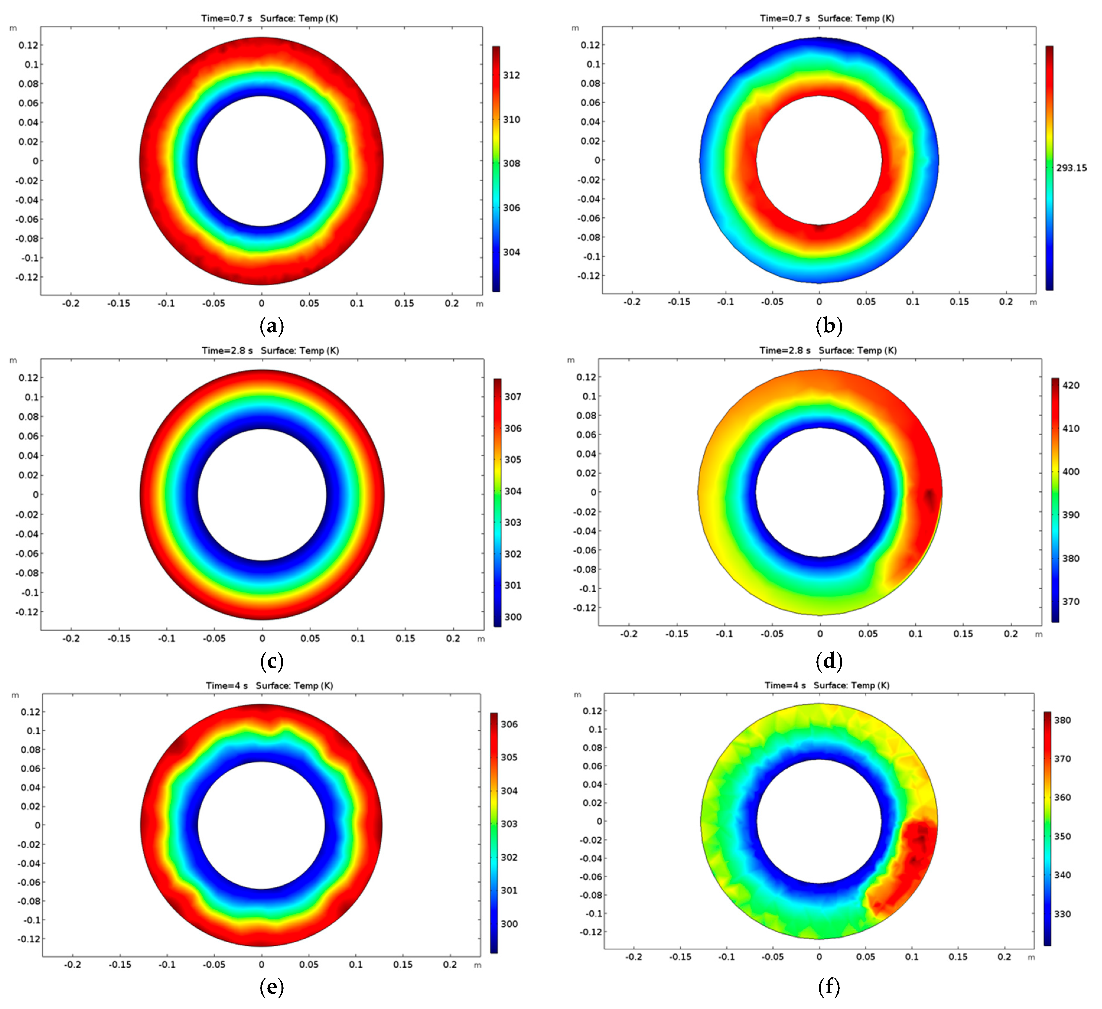
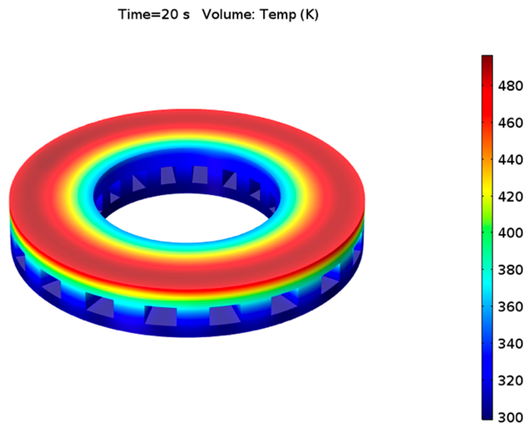
5.1. Temperature Field Analysis for the Integrated Brake

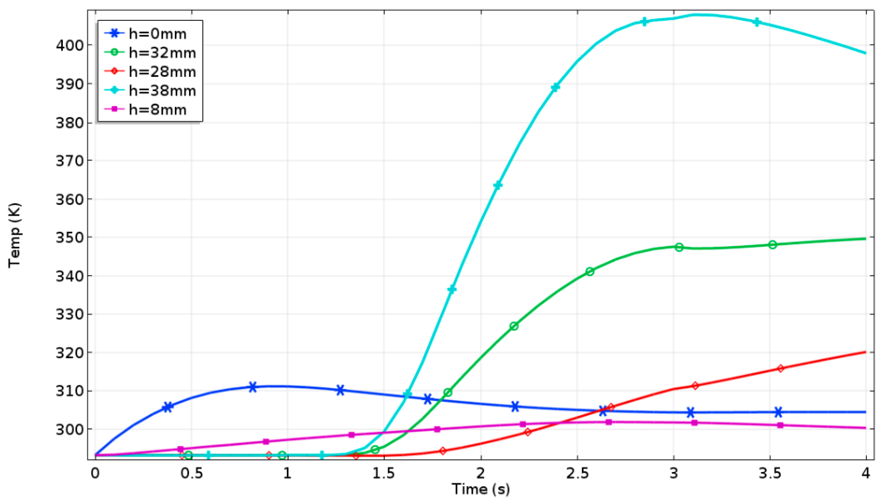
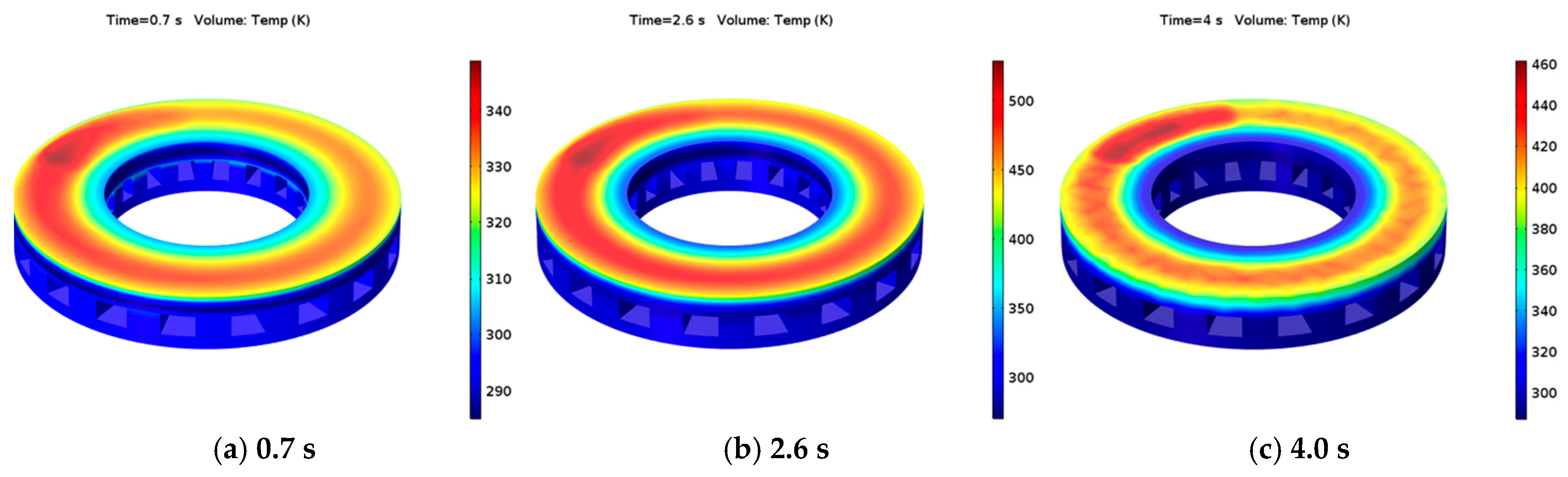
5.1.1. Emergency Braking Condition

The emergency braking condition analyzed refers to the vehicle speed from 100 km/h to 0 km/h, the initial environmental temperature was 293.15 K, and the braking deceleration was 7 m/s2. According to the integrated brake’s working modes, in the emergency braking condition, the electromagnetic brake works independently at the initial stage of braking, then the electromagnetic brake and the friction brake work simultaneously, and finally the friction brake works independently. When the integrated brake works, a moving heat source is applied to the friction surfaces of the integrated brake disc, and the current is applied to the coils of the electromagnetic brake. The cloud charts of temperature distribution of the integrated brake disc at different times are shown in Figure 5.
As shown in Figure 5, the electromagnetic brake worked and the friction brake did not during the first 0.7 s of braking time. The non-contact braking and short braking time, led to a very small temperature rise at the electromagnetic brake’s surface, and the maximum temperature reached 315 K. The maximum temperature of the friction brake surface was close to the initial temperature, and the temperature rise of the electromagnetic brake surface had little effect on the friction brake surface. When the braking time was 2.8 s, the friction brake and the electromagnetic brake worked synchronously, the temperature of the friction brake surface rose significantly, and the maximum temperature was 420 K. The temperature of the electromagnetic brake surface decreased slightly, and its maximum temperature was 307 K. When the braking time was 4.0 s, the electromagnetic brake did not work and the friction brake was coming to an end, therefore the temperatures of the two kinds of brake surfaces decreased.
At different braking moments, the friction brake’s surface reflected the influence of moving heat source in the circumferential direction. In the early braking stage, due to the large heat flux, small heat dissipation, and rapid temperature rise, the movement of heat source resulted in a high temperature in the friction zone, while the temperature in the non-friction zone was relatively small, and the circumferential temperature gradient was relatively large. With decrease in the brake disc speed, because the heat flux decreased, and the heat dissipation in the zone with higher temperature was larger, the circumferential temperature difference was small at the end of braking. In electromagnetic braking, the high temperature zone of electromagnetic brake surface is mainly the distribution area corresponding to the electromagnets. This is because the eddy current density in this area is relatively high, and the temperature rise of the brake disc is caused by eddy current loss as heat source.
During emergency braking, the calculated temperature curves on the electromagnetic brake surface and the friction brake surface are shown in Figure 6.
From Figure 6, it can be seen that the temperature of friction brake surface increased first and then decreased, the temperature of electromagnetic brake surface increased first and then changed gently. At first, only the electromagnetic brake worked, and the friction brake started working at 1.2 s. When the braking time exceeded 2.8 s, with the decrease of vehicle speed, the rate of heat production of friction brake was gradually lower than that of heat dissipation, and the temperature of friction brake disc began to drop. Finally, the temperature of friction brake surface was 368 K, and that of electromagnetic brake surface was 306 K.
The temperature curves of four nodes at the friction radius (r = 105 mm) and phase angles (0 degree, 90 degree, 180 degree, and 270 degree, respectively) on the friction brake surface are shown in Figure 7. The temperature change trend of each node was similar. However, the temperature peaks and troughs occured at different time points due to the alternating action of friction heat source and convective heat transfer.
The calculated temperature curves at different radial positions of the friction brake surface are shown in Figure 8. The temperature at the radius (r = 105 mm) was the highest, because this is the friction radius.
The radial temperature distribution of electromagnetic brake surface is shown in Figure 9. In the initial stage of braking, the temperature of the electromagnetic brake surface increased rapidly because of electromagnetic braking operation and less convective heat transfer, from 293 K to 312 K. Thereafter, the heat generated by electromagnetic braking decreased gradually, with the decrease of vehicle speed. At the later stage of braking, the convective heat transfer and the generated heat basically reached equilibrium, and the temperature curves tended to be flat.
Five points of different thickness of the integrated brake disc were selected at the friction radius (r = 105 mm). Among them, h = 0 was the electromagnetic brake surface, h = 38 mm was the friction brake surface, and the other three points were located between the electromagnetic brake surface and the friction brake surface. Figure 10 shows that the trend of temperature change at point h = 32 mm was similar to that at the friction brake surface, but the temperature was much lower than that at the friction brake surface, indicating that the heat source at the point mainly comes from thermal radiation of the friction brake surface. The temperature curves at h = 8 mm and h = 28 mm showed a gentle upward trend, it can be seen that heat sources of the brake surfaces had no obvious effect on them. At the end of braking, the temperature of each point tended to converge, which showed that the integrated brake disc had good thermal conductivity.

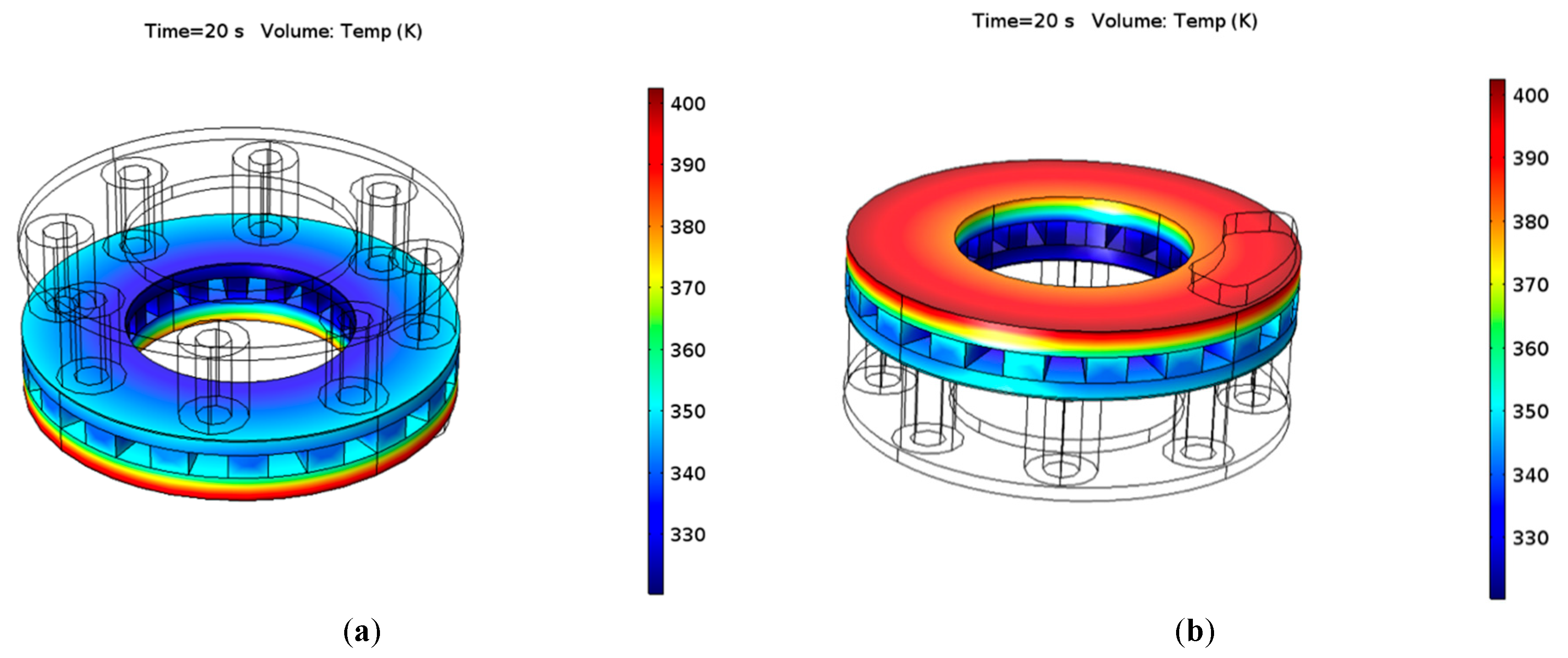
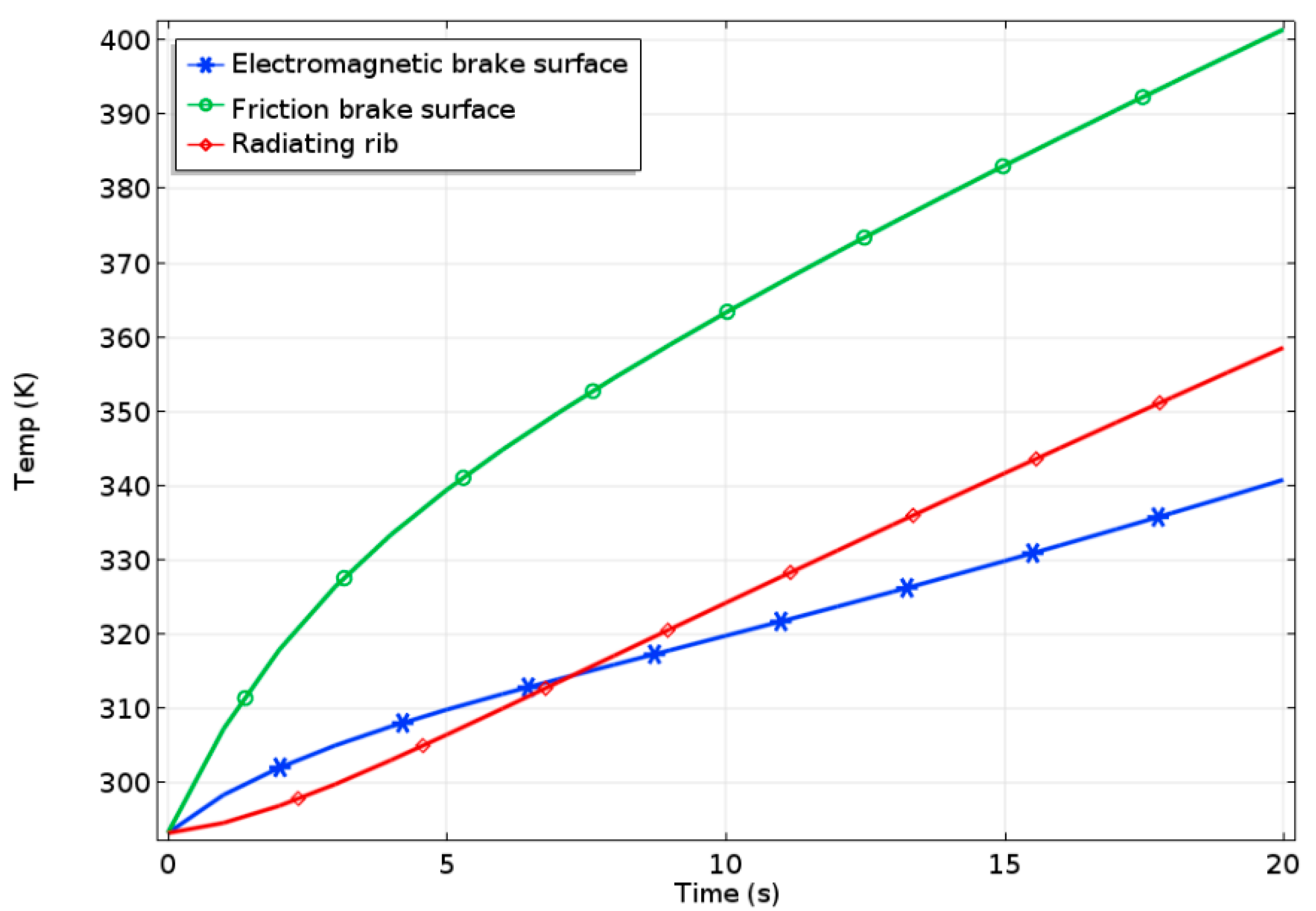
5.1.2. Downhill Braking at a Constant Speed

During the downhill braking at a constant speed, the vehicle speed was set to 50 km/h and the continuous braking time was set to 20 s, the initial environmental temperature was 293.15 K, and the slope of downhill was 7%. When braking for 20 s, the cloud charts of temperature field of the integrated brake disc are shown in Figure 11, and the temperature curves of electromagnetic brake surface, friction brake surface, and radiating rib are shown in Figure 12.
Figure 11 and Figure 12 show that temperatures of electromagnetic brake surface, friction brake surface and radiating rib showed upward trends during the braking at a constant speed. The temperature rise of radiating rib was the lowest in the initial braking stage, because the temperatures of the electromagnetic brake surface and the friction brake surface were lower, and the heat transmitted to the radiating rib was very small. With the increase of time, the temperatures of the electromagnetic brake surface and the friction brake surface increased rapidly. However, the temperature rise of the friction brake surface was much larger than that of the electromagnetic brake surface, the heat source of the radiating rib mainly came from the friction brake surface, which made the temperature of the radiating rib between that of electromagnetic brake surface and that of friction brake surface. At the end of braking, the temperature of the friction brake surface was 402 K, and that of electromagnetic brake surface was 341 K, which showed that the temperature rise of friction brake surface had little effect on the electromagnetic brake surface. The heat was transferred from a high-temperature object to a low-temperature object and the temperature rising speed of friction brake was faster than that of electromagnetic brake, thus the influence of electromagnetic brake on the temperature rise of friction brake can be neglected.

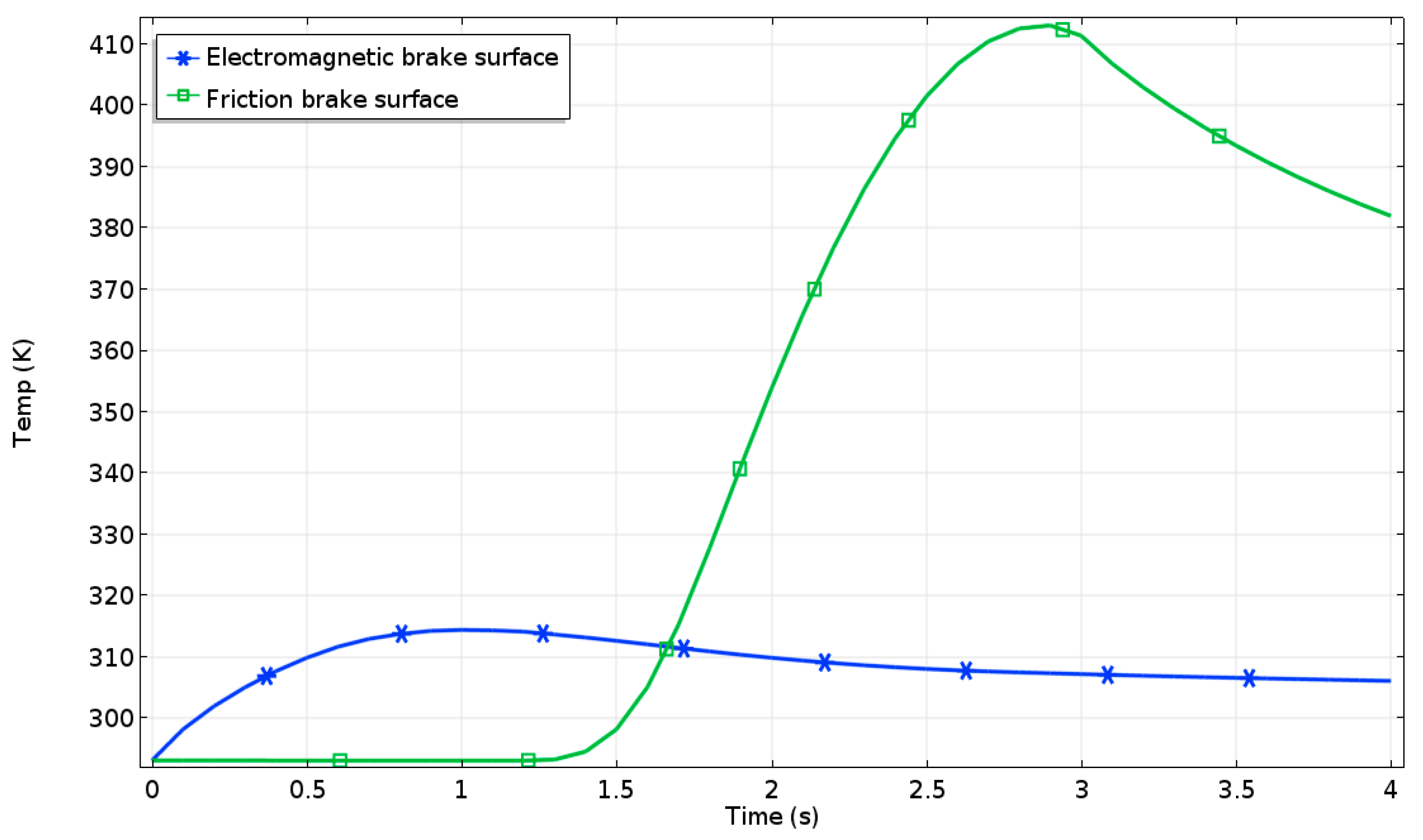
5.2. Comparative Analysis of the Integrated Brake and Traditional Friction Brake

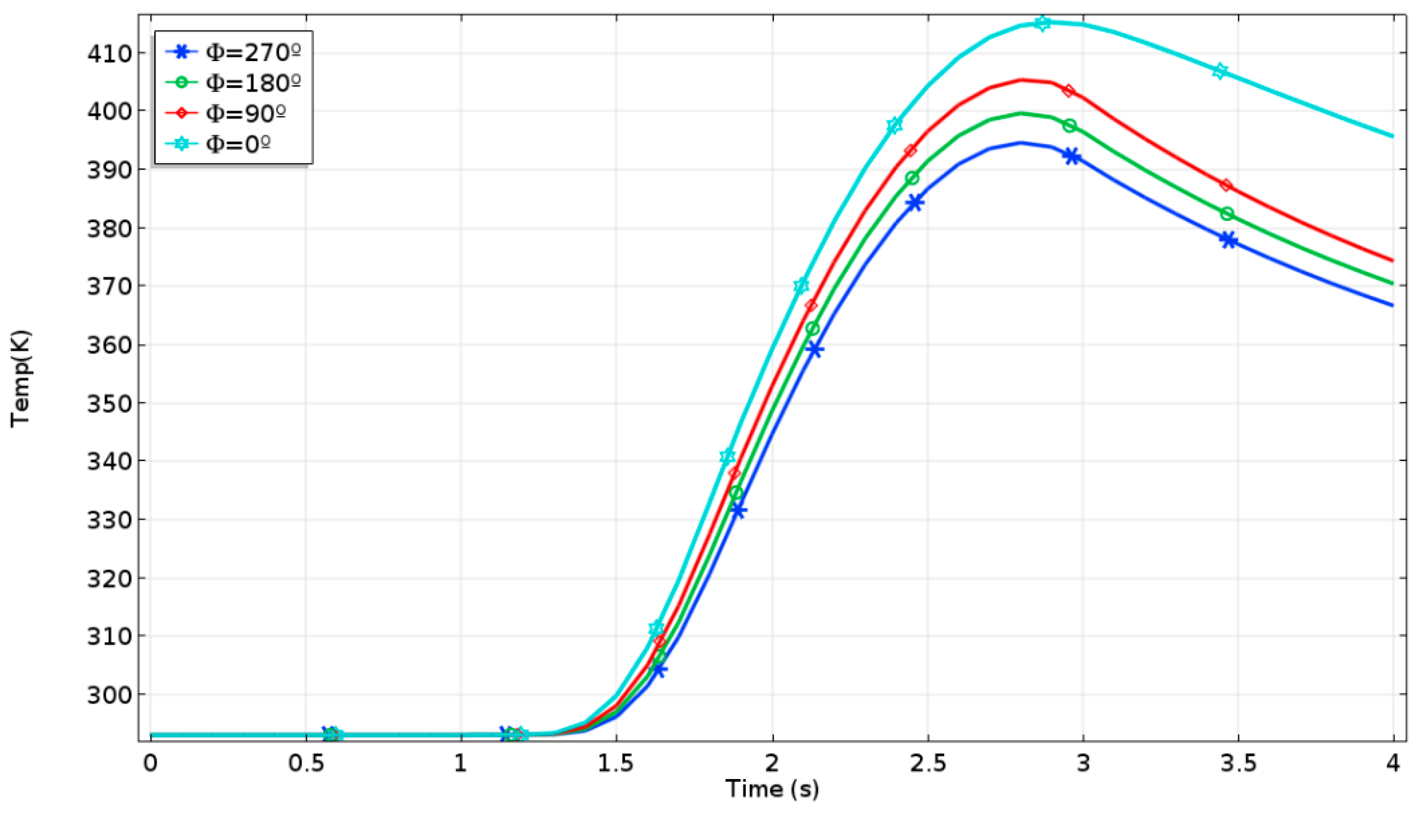
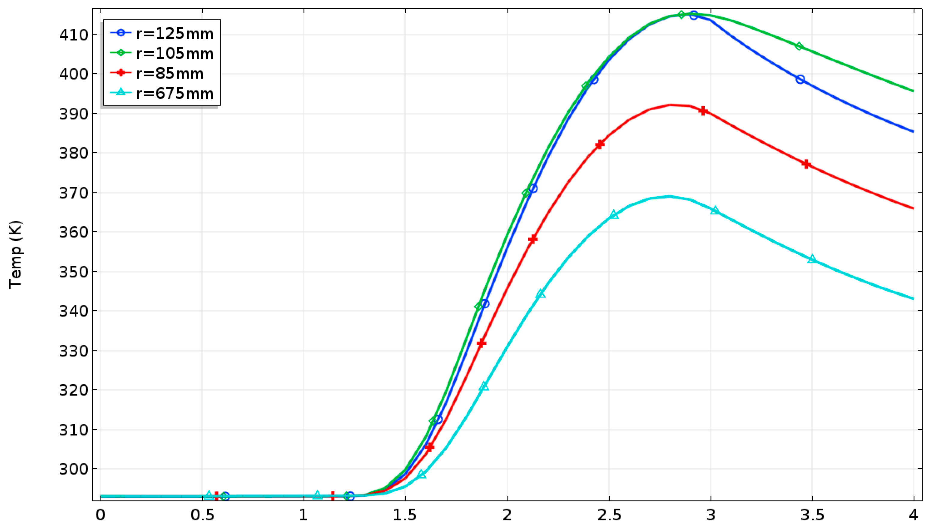
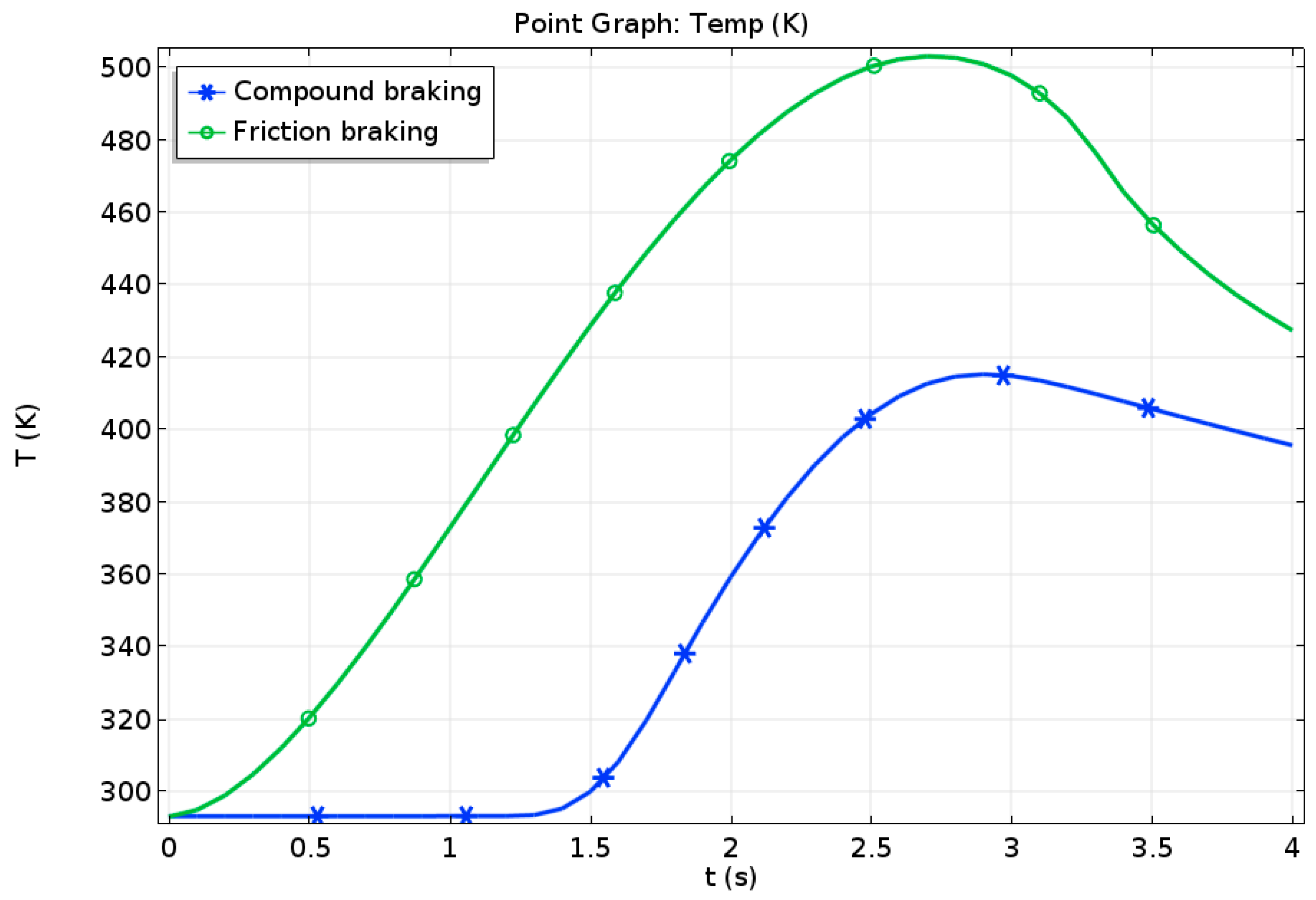
5.2.1. Emergency Braking Condition

The model of traditional friction brake was established with the same structure parameters and material settings. Under the same braking conditions, the analysis on single emergency braking of traditional friction brake was carried out. The calculated cloud charts of temperature change of traditional friction brake disc are shown in Figure 13.
As shown in Figure 13, the high temperature area of traditional friction brake disc was the contact area between the brake pads and the brake disc. With the increase of braking time, the temperature of brake disc increased first and then decreased, which was same as that of the integrated brake. When braking for 2.6 s, the temperature of the brake disc reached a maximum of 500 K, and the final braking temperature was 460 K, both of which were higher than those of integrated braking.
The contrast curves of temperature rise for two different braking forms are shown in Figure 14. The temperature of electromagnetic-frictional integrated brake was obviously lower than that of the traditional friction brake, and its maximum temperature decreased by ~39%.

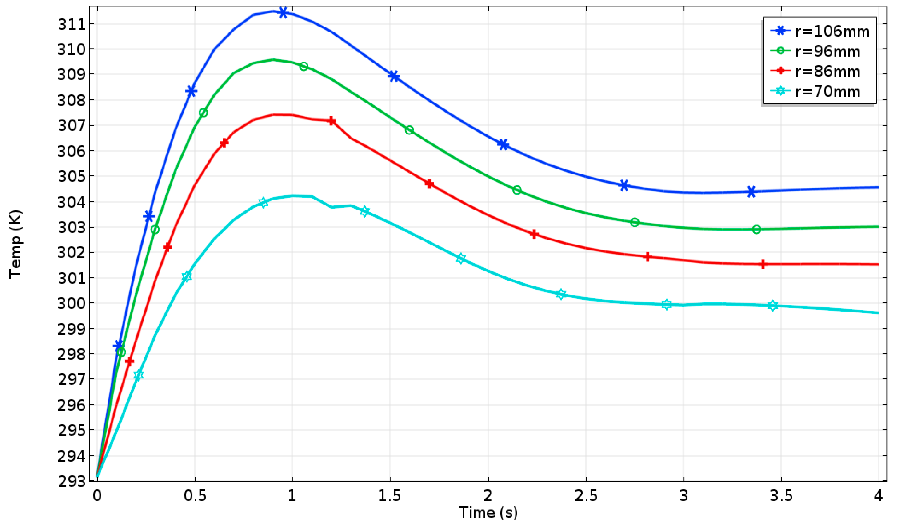
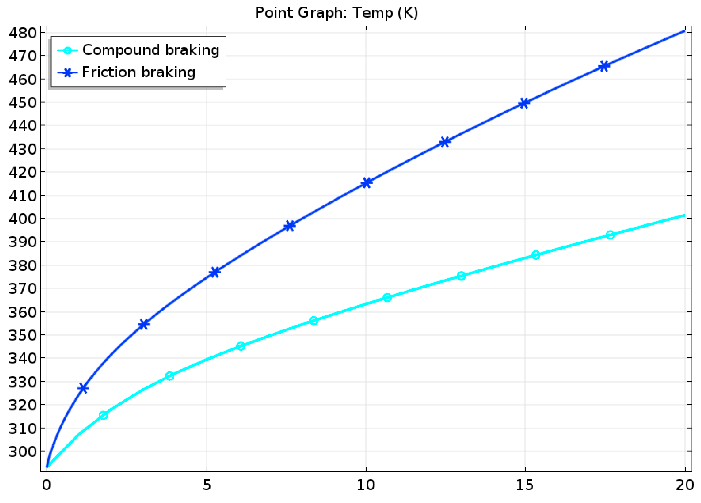
5.2.2. Downhill Braking at a Constant Speed

At the end of downhill braking at a constant speed, the calculated cloud charts of temperature distribution for the traditional friction brake disc is shown in Figure 15. Its maximum temperature was 482 K, which was higher than that of compound braking.
The contrast curves of temperature rise for two different braking forms are shown in Figure 16. In the process of downhill braking at a constant speed, the difference between the temperature of traditional friction brake and that of integrated brake was increasing. The final temperature of traditional friction brake was 482 K and that of integrated brake was 402K. Compared with the traditional friction brake, the temperature rise of integrated brake was reduced by about 42%.

6. Conclusions

In this paper, a new electromagnetic-frictional integrated brake is proposed. The structural principle and working modes of the proposed integrated brake are introduced, and its three-dimensional model and mathematical models are established. Based on the multi-field coupling theory of electro-magnetic-thermal-solid and the COMSOL software, the numerical simulation and analysis on the proposed integrated brake are carried out respectively in the emergency braking and the downhill braking at a constant speed. The temperature rise of integrated brake is compared with that of traditional friction brake. Compared with the traditional friction braking, the results show that the proposed integrated brake can effectively improve the heat fading resistance under the two selected braking conditions. These lay a theoretical foundation for subsequent prototype fabrication and performance tests.

Author Contributions

R.H.; methodology, R.H. and K.W.; software, K.W. and J.T.; validation, R.L. and J.T.; formal analysis, J.T.; investigation, K.W.; resources, K.W.; data curation, R.L.; writing—original draft preparation, K.W.; writing—review and editing, R.H.; visualization, J.T.; supervision, R.H.; project administration, R.H. and R.L.; funding acquisition, R.H. and R.L.

Funding

This work was jointly supported by the National Natural Science Foundation of China (grants 51705221), the National Natural Science Foundation of China (grants 51875258), Research & Innovation Foundation of General University Graduate of Jiangsu Province (grants CXZZ13_0659), and the Overseas Training Foundation for Universities of Jiangsu Province.

Conflicts of Interest

The authors declare no conflict of interest.

References

  1. Jazar, R.N. Vehicle Dynamics: Theory and Application, 3rd ed.; Springer: New York, NY, USA, 2017. [Google Scholar]
  2. Karakoc, K.; Suleman, A.; Park, E.J. Analytical Modeling of Eddy Current Brakes with the Application of Time Varying Magnetic Fields. Appl. Math. Model. 2016, 40, 1168–1179. [Google Scholar] [CrossRef]
  3. Gay, S.E. Contactless Magnetic Brake for Automotive Applications. Ph.D. Thesis, Texas A&M University, College Station, TX, USA, 2005. [Google Scholar]
  4. Song, J. Performance Evaluation of a Hybrid Electric Brake System with a Sliding Mode Controller. Mechatronics 2005, 15, 339–358. [Google Scholar] [CrossRef]
  5. Gay, S.E.; Ehsani, M. Parametric Analysis of Eddy-Current Brake Performance by 3-D Finite-Element Analysis. IEEE Tran. Magn. 2006, 42, 319–328. [Google Scholar] [CrossRef]
  6. Anwar, S.; Zheng, B. An Antilock-Braking Algorithm for an Eddy-Current-Based Brake-By-Wire System. IEEE Tran. Veh. Tech. 2007, 56, 1100–1107. [Google Scholar] [CrossRef]
  7. Liu, C.; He, R. Structure Analysis of Composition of Frictional Brake and Contactless Wheel Retarder System. Trans. Chinese Soc. Agrc. Mach. 2010, 6, 25–30. (In Chinese) [Google Scholar]
  8. Wang, K.Y.; Tang, J.H.; Li, G.Q.; Yuan, C.Y. Optimal Design of Vehicle Disc Brake Integrated Electromagnetism and Friction. Mach. Design Manuf. 2013, 3, 132–135. (In Chinese) [Google Scholar]
  9. Tang, J.H.; Wang, K.Y.; Bei, S.Y. Numerical Simulation of Electromechanical Composite Brake Based on Multi Field Coupling. J. Balkan Trib. Assoc. 2016, 3, 2265–2280. [Google Scholar]
  10. Tang, J.H.; Wang, K.Y.; Zhang, L.C.; Li, G.Q. Temperature Analysis on Electromechanical Composite Brake of Automobile Based on Numerical Simulation. Acta Technica 2016, 61, 219–230. [Google Scholar]
  11. Yin, Y.; Bao, J.; Liu, J.; Guo, C.; Liu, T.; Ji, Y. Braking Performance of a Novel Frictional-Magnetic Compound Disc Brake for Automobiles. Proc. Inst. Mech. Eng. Part D J Auto. Eng. 2018, 1–12. [Google Scholar] [CrossRef]
  12. Zhao, K.; Wei, L. 3D Thermo-mechanical Coupling Temperature Field Simulation of Drum Brake. Trans. Chinese Soc. Agric. Mach. 2009, 40, 32–36. (In Chinese) [Google Scholar]
  13. Wang, Y.; Cao, X.; Yao, A. Study on the Temperature Field of Disc Drake Friction Flake. J. Wuhan Univ. Tech. 2001, 7, 22–24. (In Chinese) [Google Scholar]
  14. Shi, J. Design of double disc friction and electromagnetic integrated brake of car and research of its temperature field. Master’s Thesis, Jiangsu University, Zhenjiang, China, 2014. [Google Scholar]
  15. Su, S.; Kong, W.; Chen, D. (Eds.) Simulation and Design of Thermal Energy Engineering and Advanced Energy Technology; Chemical Industry Press: Beijing, China, 2015. [Google Scholar]
  16. Yu, W. The simulation and analysis of the transient temperature field of automotive disk brake. Master’s Thesis, Hefei University of Technology, Hefei, China, 2009. [Google Scholar]
Figure 1. Structural diagram of electromagnetic-frictional integrated brake. 1, brake fluid; 2, brake piston; 3, brake pad; 4, caliper body; 5, integrated brake disc; 6, copper layer; 7, friction brake surface; 8, electromagnetic brake surface; 9, coil; and 10, iron core.
Wevj 10 00009 g001
Figure 2. Three-dimensional model of the integrated brake.
Wevj 10 00009 g002
Figure 3. Computational domain of the integrated brake model.
Wevj 10 00009 g003
Figure 4. Calculation model of the integrated brake after meshing.
Wevj 10 00009 g004
Figure 5. Cloud charts of temperature distribution of integrated brake disc. (a) Electromagnetic brake surface at 0.7 s; (b) Friction brake surface at 0.7 s; (c) Electromagnetic brake surface at 2.8 s; (d) Friction brake surface at 2.8 s; (e) Electromagnetic brake surface at 4.0 s; (f) Friction brake surface at 4.0 s.
Wevj 10 00009 g005
Figure 6. Temperature curves of integrated brake disc during emergency braking.
Wevj 10 00009 g006
Figure 7. Circumferential temperature distribution of friction brake surface.
Wevj 10 00009 g007
Figure 8. Radial temperature distribution of friction brake surface.
Wevj 10 00009 g008
Figure 9. Radial temperature distribution of the electromagnetic brake surface.
Wevj 10 00009 g009
Figure 10. Temperature curves of different axial points of the integrated brake disc.
Wevj 10 00009 g010
Figure 11. Cloud charts of temperature distribution of the integrated brake disc. (a) Electromagnetic brake surface; (b) Friction brake surface.
Wevj 10 00009 g011
Figure 12. Temperature curves of the integrated brake disc.
Wevj 10 00009 g012
Figure 13. Cloud charts of temperature distribution of traditional friction brake disc.
Wevj 10 00009 g013
Figure 14. Contrast curves of temperature rise for two different braking forms.
Wevj 10 00009 g014
Figure 15. Cloud charts of temperature distribution for traditional friction brake disc.
Wevj 10 00009 g015
Figure 16. Contrast curves of temperature rise for two different braking forms.
Wevj 10 00009 g016
Table 1. Partial vehicle parameters of BYD Qin.
NameValue
Total mass (m)2095 kg
Wheelbase (L)2670 mm
Front axle load (Ff)1119 kg
Rear axle load (Fr)976 kg
Wheel radius (Rb)318 mm
Table 2. Attribute parameters of related materials.
MaterialsRelative Permeability μrConductivity γ (s/m)Relative Dielectric Constant
Air1101
Brake disc2001061
Copper layer15.998 × 1071
Iron core40001.03 × 1071

