1. Introduction
Nowadays, automotive manufacturers are focused on electricity in order to maximize cars’ efficiency as well as to meet the emission standards. In particular, Chinese manufacturers become the world’s largest electric vehicle production market. Lightweight materials, advanced manufacturing processes and special electric chassis design are set to be the main focus for improving the energy efficiency of electric cars’ structures [
1,
2,
3].
Towards this direction, the goal of the current work is the development of a modeling and simulation methodology for the future electric car’s chassis. As a case study, a space frame chassis is used, which was designed for the racing competition Shell Eco Marathon [
4] and complied with its rules and regulations [
5]. Τhe present publication has been revealed through the development of previous works. The design and manufacturing of the aforementioned space frame chassis was presented in [
6] as well as both modeling and simulation steps in [
7,
8].
Generally, a crucial role on the maximization of electric car’s efficiency is the achievement of lightweight and stiff car’s structures. Undoubtedly, chassis is one of the most important elements of the structure. Hence, it must be designed optimally to reduce its weight while enhancing overall car performance. Common lightweight urban vehicles are often employing space frame structures in order to meet strength, low manufacturing cost and aesthetic demands [
9,
10]. Examples of electric cars with space frame are found in literature [
11,
12]. Furthermore, an example of an aluminum space frame chassis is presented in bibliography [
12]. Also, hydrogen fuel cell powered car’s chassis for Shell Eco Marathon is found in work [
13].
Obviously, the need for lower conceptual design costs in shorter time in conjunction with the need for new modeling techniques, lead the automotive companies to find better ways to develop vehicles. Simulation through finite element analysis (FEA) is a cost and time efficient way to develop electric car chassis whereas at the same time provides innovative product development. Another important point to be considered is the modeling methodology in which a chassis structure is studied [
14]. Specifically, these works [
15,
16,
17], using FEA, have proved that their chassis meet the strength requirements, under standard deformation modes, without calculating the exact loads which create these deformation modes. Additionally, these works [
14,
16,
17,
18,
19] proposed the chassis to be constrained at the rear axles with all DOFs and at the same time the loads were applied, especially, to the front axles of the chassis.
The novelty of the current publication is the overcoming of the time consuming conceptual design process, which is suitable for electric car’s chassis and was attained with the use of our chassis load calculator (CLC) model. Furthermore, a specialized and integrated methodology of the FEM method was developed, in which all the steps were pointed out thoroughly. Contrary to other previous works which modeled their chassis using standard deformation modes and without combined stress conditions, in the present study, the chassis was modeled after calculating the exact vehicle’s dynamic loads under a combined stress condition. This method is more accurate and helps the designers to investigate the paths and the amplitude of the loads. Finally, another great outcome of this work was the achievement of the lightest chassis in the Shell Eco Marathon competition.
2. Results and Discussion
2.1. Vehicle and Chassis Design and Specifications
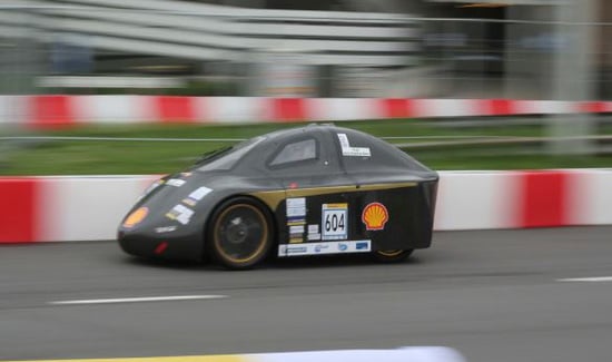
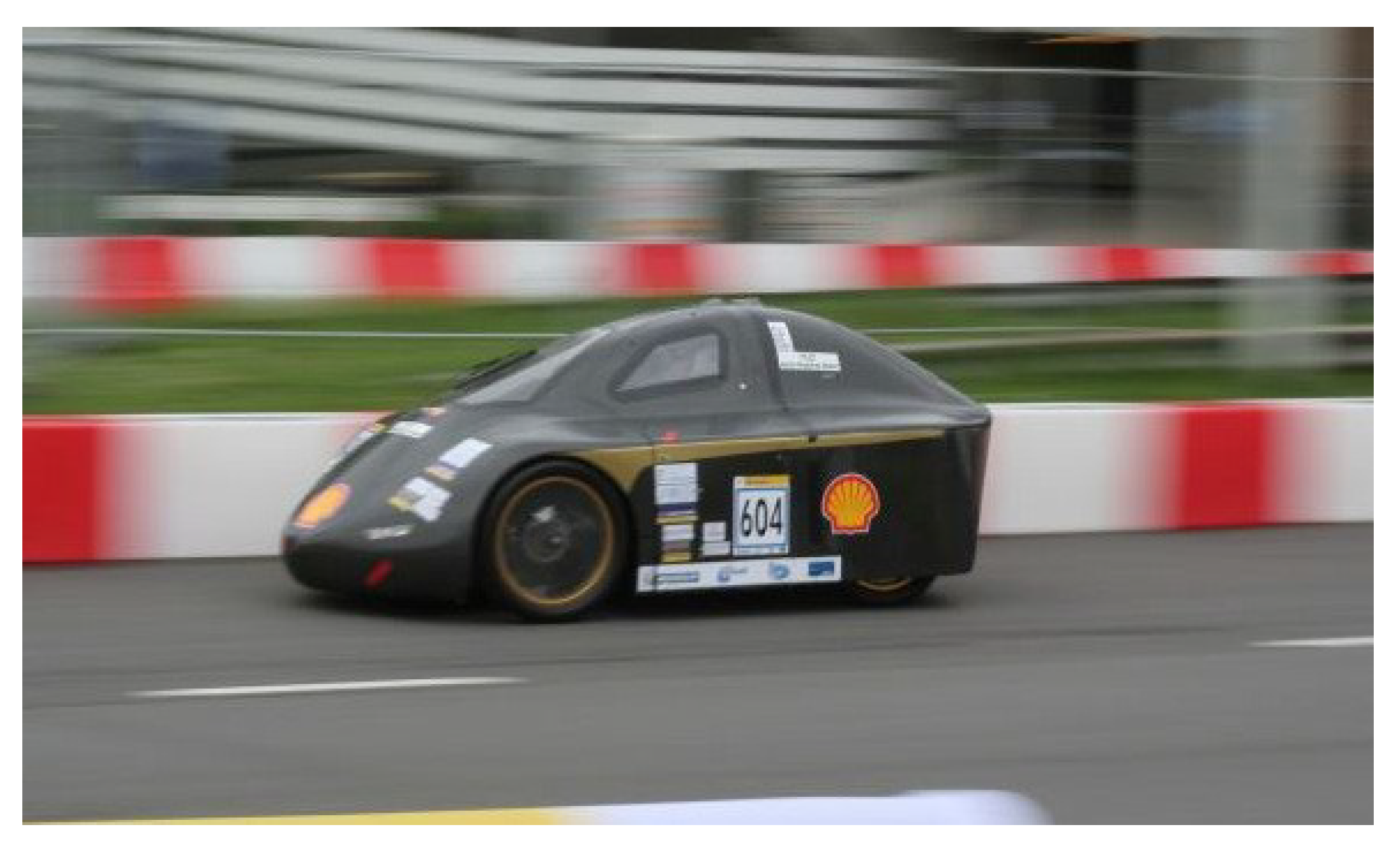
The vehicle is a one seat, four wheel car for urban environments, particular designed for the racing competition Shell Eco Marathon. The energy system of the car consists of a brushless electric motor with 4 Nm max motor torque and 4000 RPM max motor rotational frequency, powered from a 1.2 KW H
2 fuel cell. The fuel cell uses a hydrogen 200 bar bottle as a fuel tank so as to power the vehicle. The powertrain consists of one-stage geared transmission with ratio 1:10 placed between the electric motor and the wheel in order to provide the needed torque and rpm. The drag coefficient (C
d) is 0.21 and the maximum vehicle speed is 37 km/h. The body shell is 1 mm thickness carbon-fiber and it is not used as a structural part of the chassis. The dimensions of the vehicle are (2.5 × 1.25 × 1) m (L × W × H) with 1.295 m wheelbase and 0.910 m track width. The total car’s weight with the driver on seat (73 kg driver’s weight) is 155.1 kg and excluding the driver is 82.1 kg. The achieved autonomy is around 63 km/kwh and the CO
2 emissions are 0 gr [
7,
20]. The electric car is shown in
Figure 1 during the race in the Shell Eco Marathon competition [
6,
7].
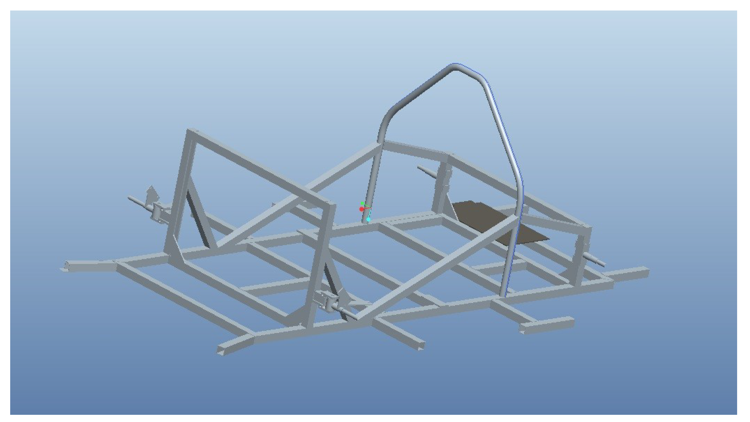
The chassis employs an aluminum space frame constructed by (30 × 30) mm 6082-T6 aluminum hollow sections with 1.5 mm wall thickness, welded together accurately. In the front-end structure, the spindle base is made of aluminum 6082-T6 and the spindle of AISI 9000 series steel. The rear end structure is made of AISI 9000 Series Steel. The dimensions of the chassis are 1.740 × 0.730 × 0.740 m (L × W × H) and its weight is 10.85 kg. The studied electric car’s space frame chassis design with the front spindle bases, the front spindles and the rear semi-axle kit is shown in
Figure 2.
Τhe properties of the AISI 9000 series steel and the aluminum 6082-T6 are shown in
Table 1 and
Table 2, respectively [
21].
The center of gravity for the chassis and the electric car were calculated in our previous paper [
6] and are shown in
Table 3 and
Table 4 respectively.
2.2. Loading Assumptions and Preparation Finite Element Model and Results
2.2.1. Worst Case Stress Scenario
The worst case stress scenario which is used in the current work has been thoroughly described in our previous paper [
8]. In this scenario, the vehicle is turning in the first corner and the wheel is positioned in the apex at 30 km/h, it encounters a stationary preceding vehicle and decelerates immediately (6 m/s
2), to avoid the accident [
22,
23,
24,
25,
26,
27,
28].
2.2.2. Chassis Load Calculator Model
The chassis load calculator (CLC) model has been presented analytically in our previous paper [
8] and it is used in the current work in order to calculate automatically the magnitude and the direction of the loads acting on the car, by importing its characteristics. The model has been implemented by the use of vehicle dynamics theory [
22,
29,
30,
31,
32,
33] and the model’s output is presented in
Table 5,
Table 6 and
Table 7.
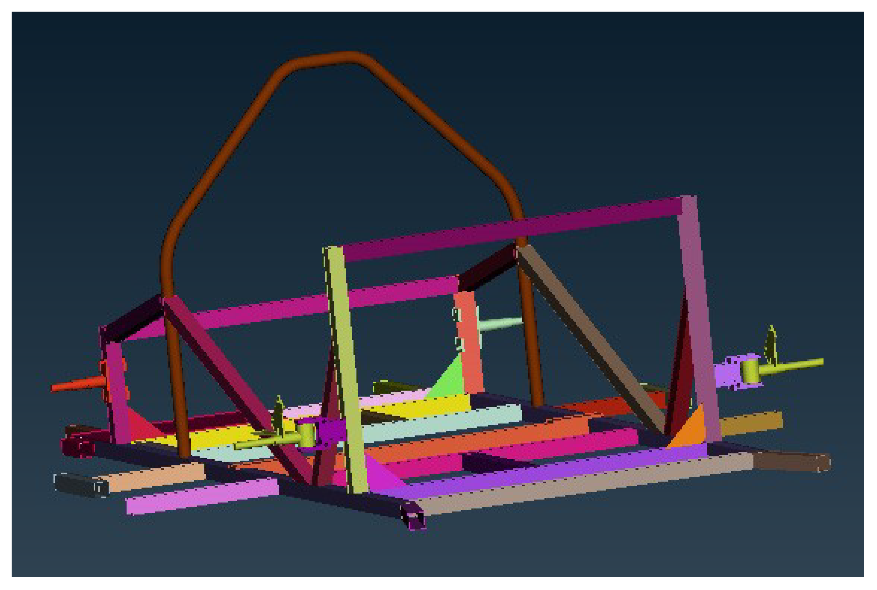
2.2.3. Pre-Processing of Data and Finite Element Modeling (FEM)
The ANSA pre-processor of the BETA CAE Systems was employed for the preparation of the model [
34]. ANSA tool ensures efficient simulation in a short time and without the need for experiments with physical models. The model was prepared properly in order to be solved, using the ANSYS solver, a software package of the Livermore Software Technology Corporation (LSTC) [
35]. Different finite element solvers can be used instead. By importing the CAD file from Pro Engineer to ANSA, the 48 different parts of the assembly were recognized and they are shown in different colors in
Figure 3.
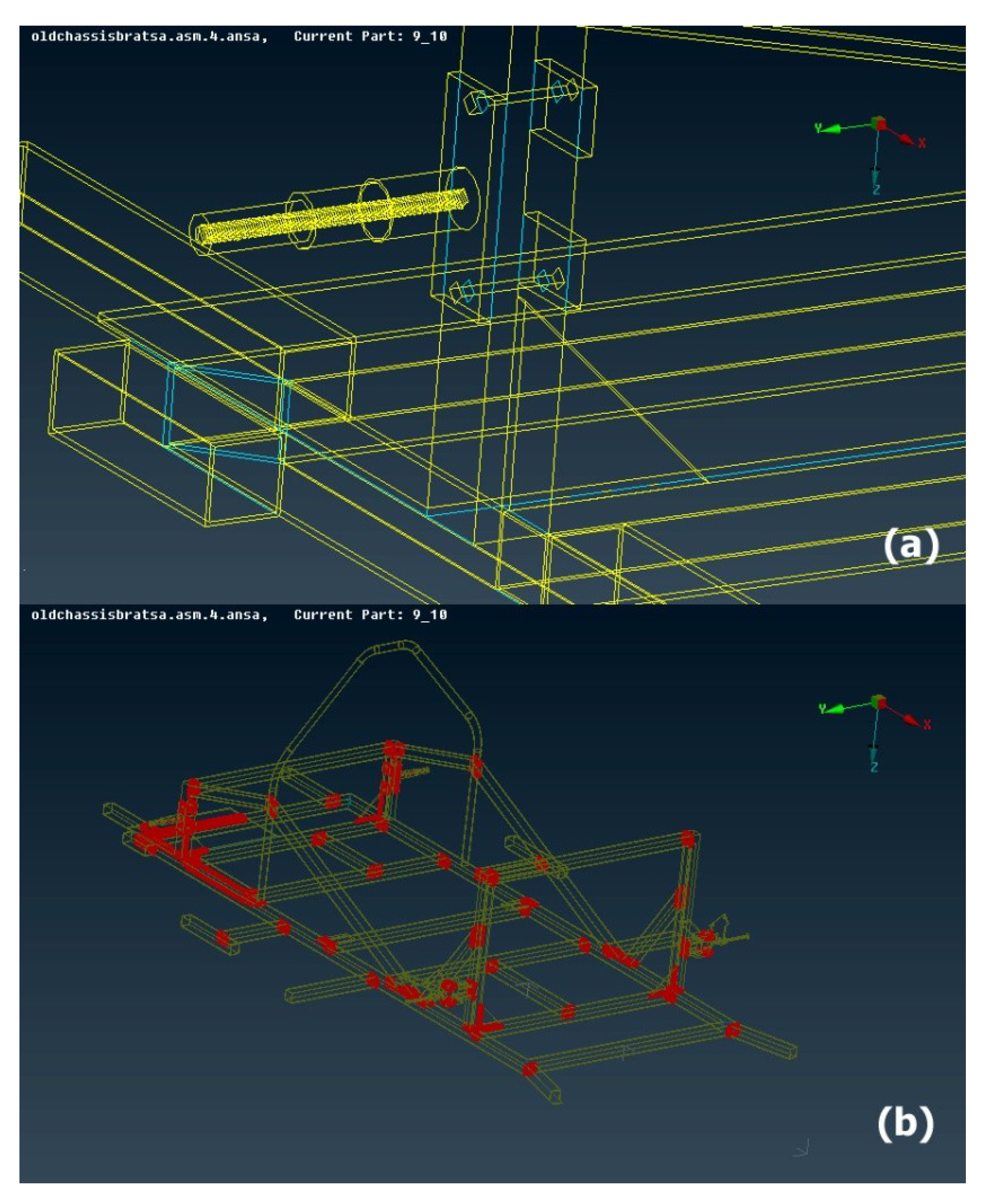
Geometry Cleanup
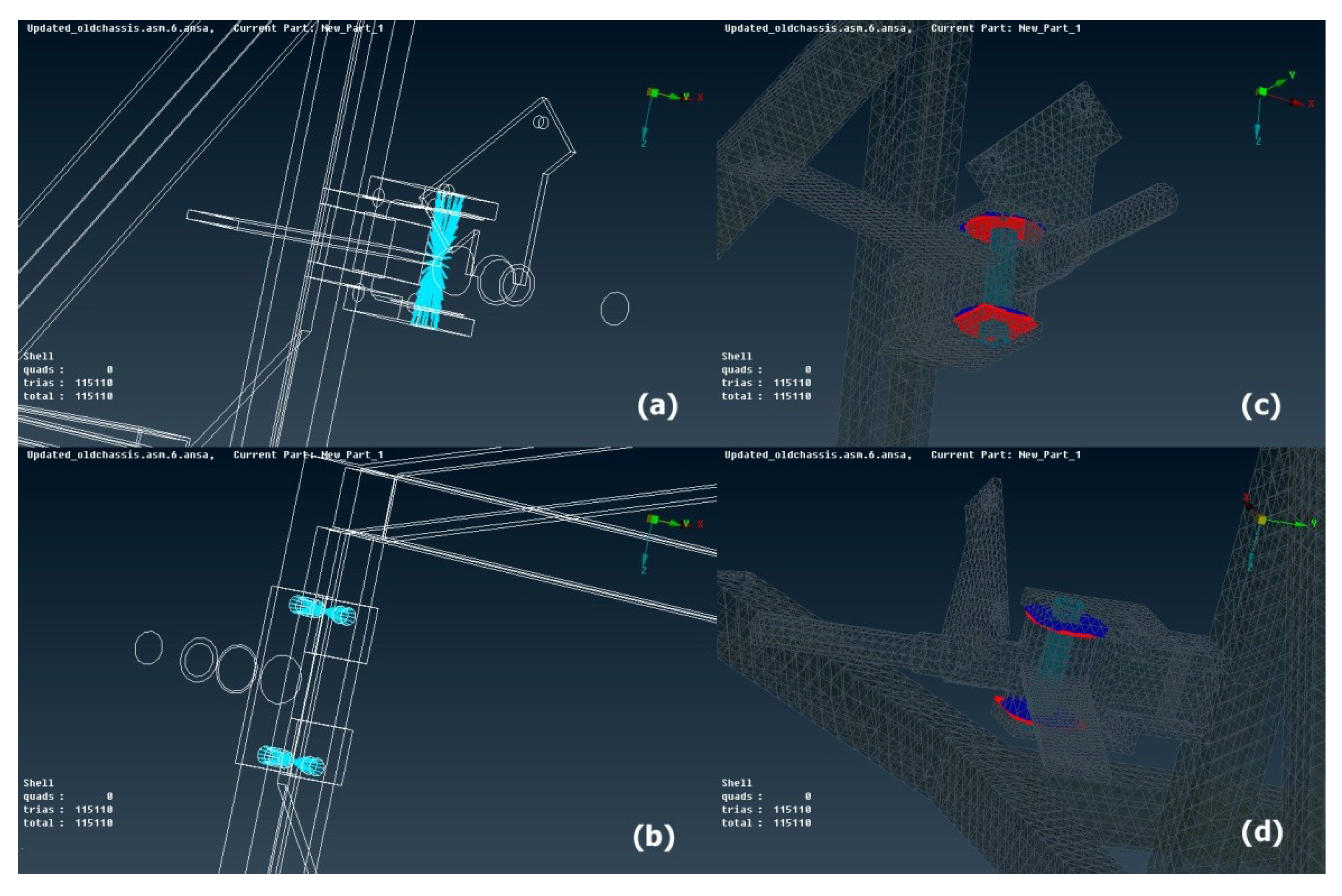
Subsequently, a geometry check was performed. Any triple cons errors were observed in cyan color as shown in
Figure 4a. Erasing the surplus cons the geometry errors were fixed. In the following, intersections check was carried out. Intersections were appeared in red color as shown in
Figure 4b. Thereafter, intersections were fixed with the use of geometry fixing tools.
Materials and Properties Definition
The aluminum 6082-T6 properties of the chassis and the front spindle base, the AISI 9000 series steel properties of the front spindle and the rear end structure were inserted into the material forms.
Shell Meshing
With the shell mesh command, an initial mesh at the surfaces of the solid was constructed. In the field of mesh parameters, the maximum and the minimum dimension of the mesh was assigned as 10 and 5 mm respectively, so as to include a great number of elements inside the model. Moreover, the meshing scenario was created in every single part separately. Regions which were anticipated to experience high changes in stress require a higher finite element mesh density than those which were anticipated to experience little or no stress variation. Additionally, points of interest such as holes, fillets or corners were meshed properly.
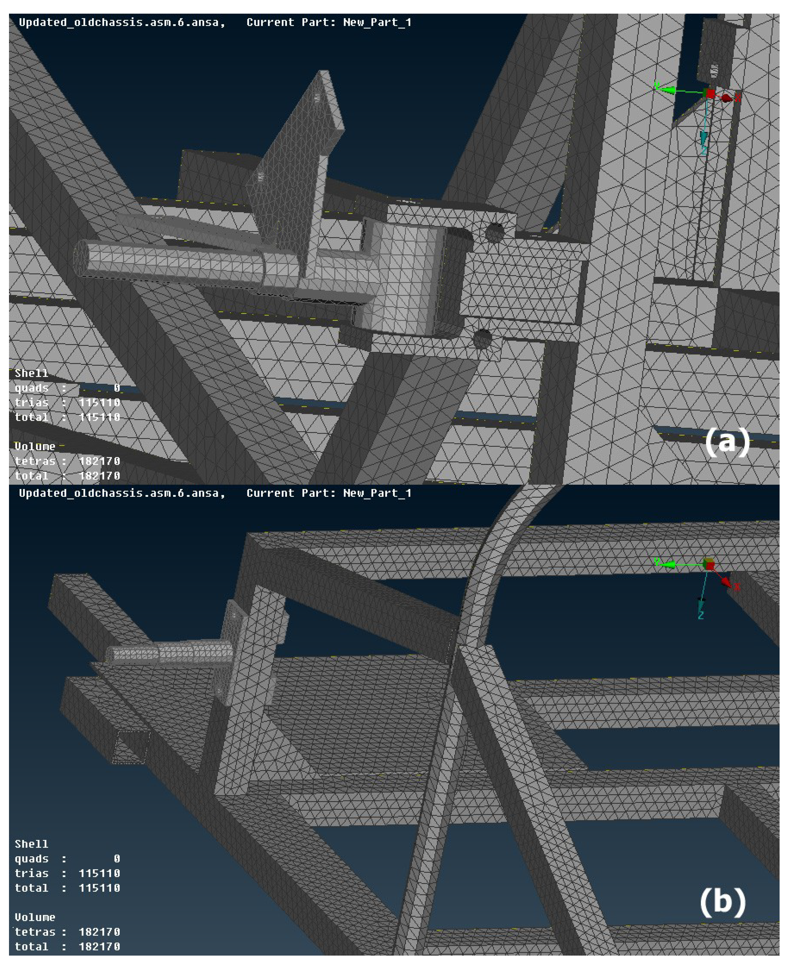
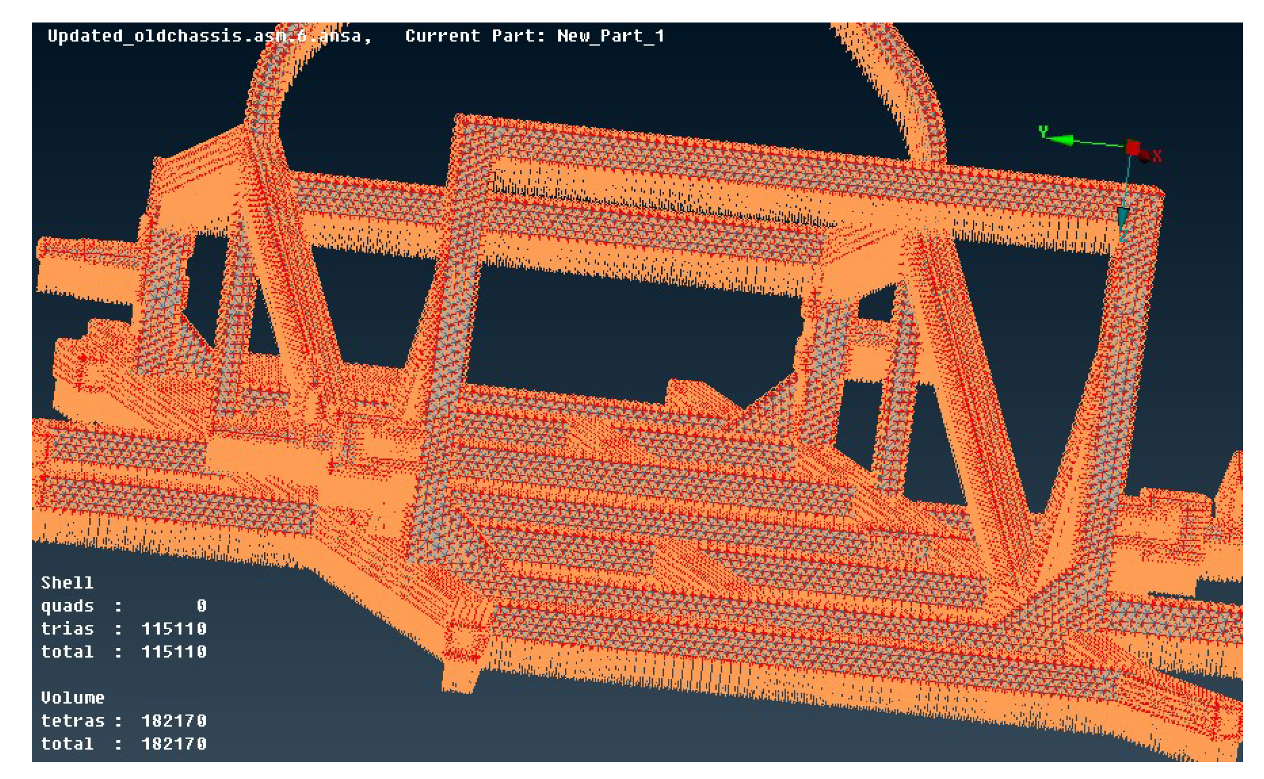
Volume Meshing
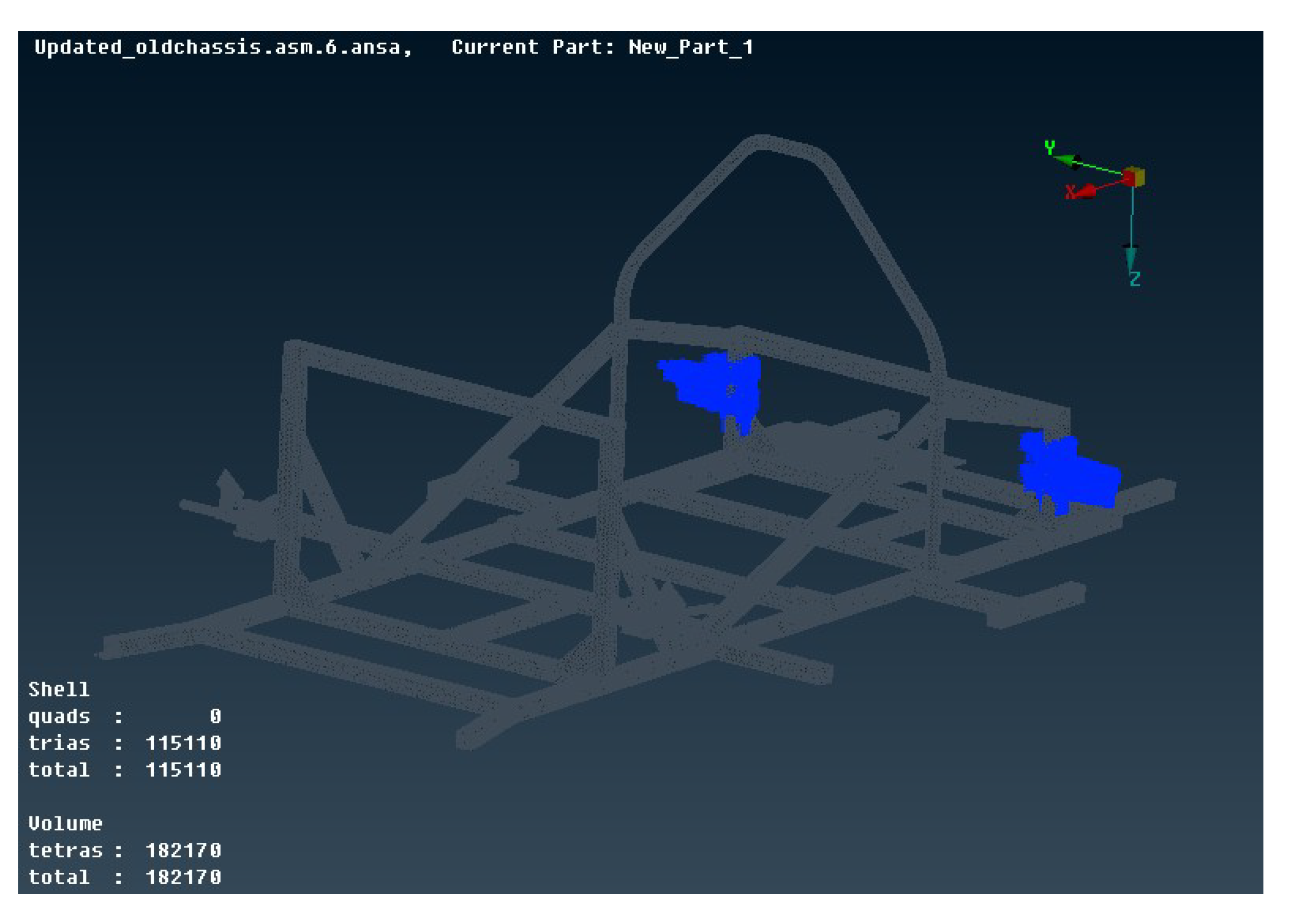
By using the already created surface mesh as a base, the volume mesh was derived by the mesh volume command. The mesh in some areas was performed with higher density compared to the rest of the model and the points of interest such as holes, fillets, or corners were meshed properly, as shown in
Figure 5. Finally, the finite element model was composed of 115,110 shell elements (trias) and 182,170 volume elements (tetras).
Meshing Check
A series of checks, negative volume check, penetration-intersections check, duplicate elements check and undefined check, were conducted in order to ensure the functionality of the model. The model was error-free and ready for further processing.
Load Step Manager
In the load step manager, one step was determined. The step includes the permanent static loads (seat plus the driver load, fuel cell load, battery light load, steering system load and electric motor load), the total dynamic loads on the front axles which act during the coexistence of braking and cornering and finally the loading constraints.
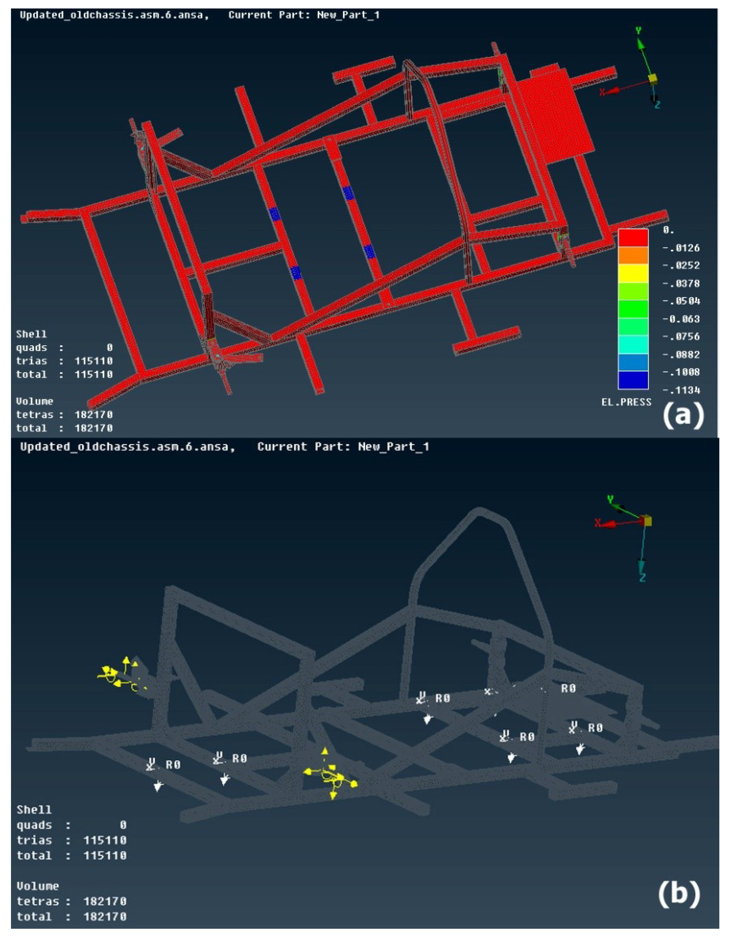
Loading Constraints Selection
In the current work, the cornering and braking load case were selected to validate the strength of the chassis. As a vehicle brakes while it is cornering, an instantaneous weight transfer occurs to the front, outside axle [
16]. At this very moment, the loads are applied especially to the front axles of the vehicle and it could be assumed that the rear axles of the vehicle remain fixed [
18,
19]. Thus, the rearmost section of the chassis was selected to be constrained with all DOF’s (123456) as shown in
Figure 7 [
14,
17].
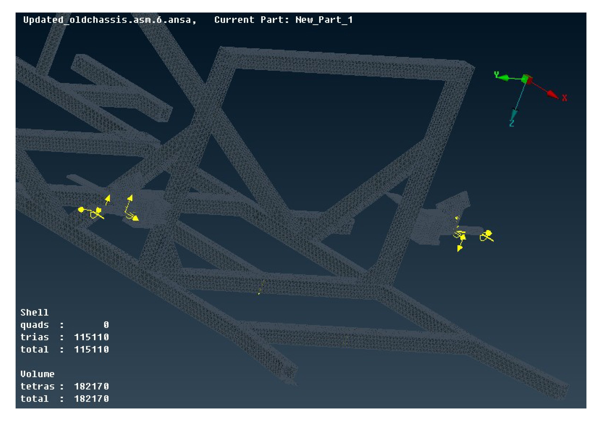
Front Axle Loads
Thereupon, the longitudinal, the lateral and the vertical nodal forces as well as the roll and the pitch nodal moments were applied on the front axles as shown in
Figure 8.
Permanent Static Loads
The permanent static loads are the pressure which is applied from the total driver’s weight plus the seat’s weight, the fuel cell force, the battery light force, the steering system force, and the electric motor force. The fuel cell force is assembling at the rear side of the chassis by four bases. The total load of the fuel cell is applied on the chassis through these four bases.
The pressure which is applied from the driver (73 kg driver’s weight) plus the seat (2 kg seat’s weight) was calculated, dividing the force applied by both the driver and the seat by the area that the driver’s seat takes up on the chassis. However, there are four seat bases, which occupy four equal areas, so we have four equal pressures applied on the chassis. Each one of the four pressures can be calculated by
where W is the weight of the driver plus the seat; F is the force which is applied by the driver plus the seat; F1, F2, F3, and F4 are the four equal forces which are applied by the driver plus the seat through the four bases; A is the total area that the driver’s seat takes up on the chassis; A1, A2, A3, and A4 are the four equal areas that the four seat bases takes up on the chassis; P is the total pressure which is applied from the driver plus the seat on the chassis and P1, P2, P3, and P4 are the four equal pressures that the four seat bases apply on the chassis.
The permanent static pressure of the total driver’s weight plus the seat’s weight was applied on the elements of the model as shown in
Figure 9a and the permanent static forces (fuel cell forces, battery light force, steering system force, and electric motor force) were applied on the nodes of the model as shown in white colors in
Figure 9b. The battery, steering system and electric motor forces are 19.62, 68.67, and 29.43 N, respectively. The fuel cell force is divided into four forces resulting in 29.43 N per force.
Gravity Acceleration
Finally, the gravity acceleration was taken under consideration (9810 mm/s
2) on the
z-axis as shown in
Figure 10.
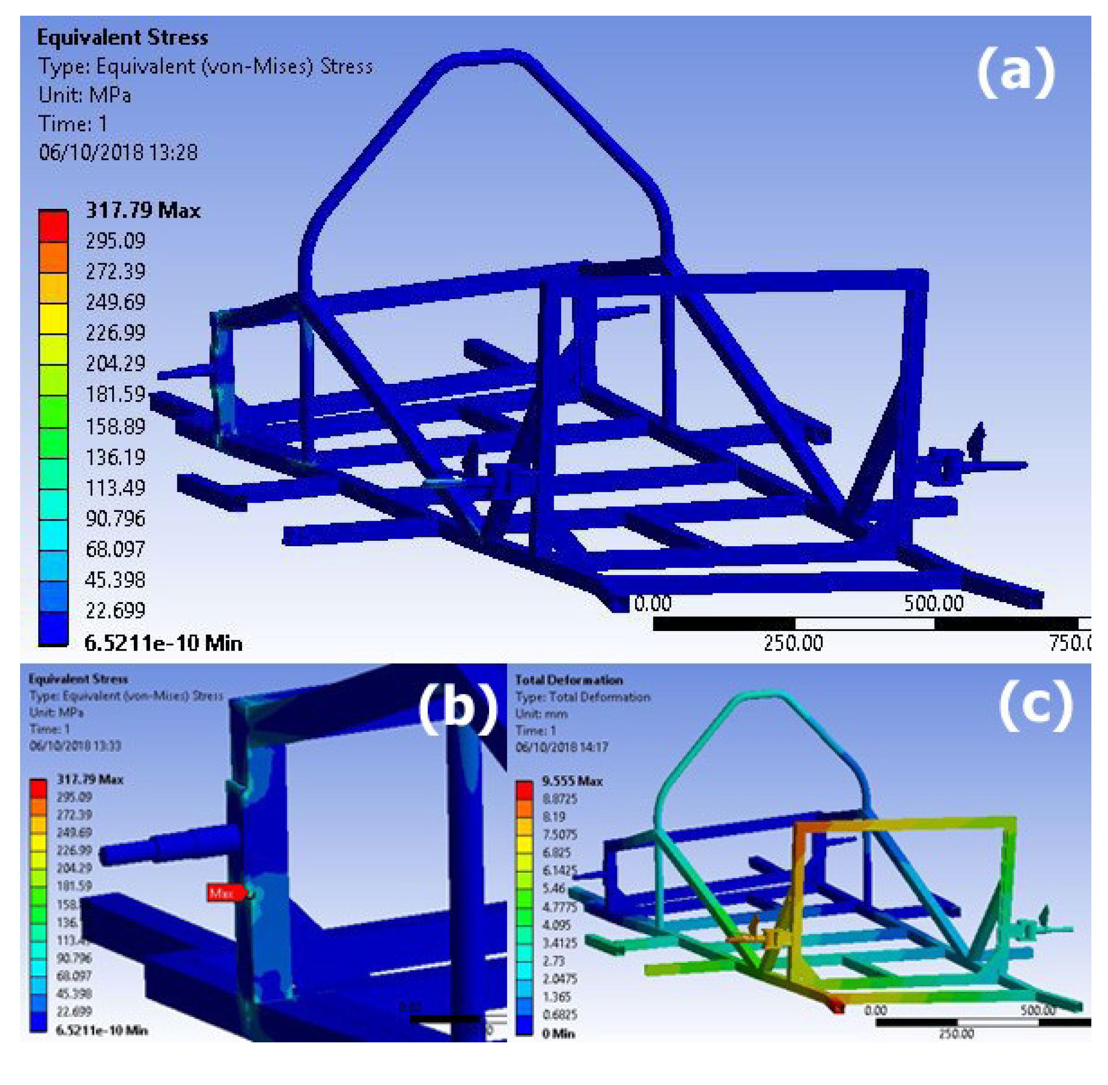
2.2.4. FEM Results
The linear static analysis was performed by the Ansys solver. The equivalent von Mises stresses and deformations of the assembly structure are presented in
Figure 11. The results present a maximum stress value of 317.79 MPa and deformations up to 9.55 mm, both being considered acceptable. Specifically, the maximum stress value of 317.79 MPa is presented in the rear semi-axle kit, which is made of stainless steel with yield strength 850 Mpa, moreover in the space frame, which is made of aluminum with yield strength 255 Mpa, the maximum stress is 226.99 Mpa, as shown in
Figure 11b. A 8 GB RAM, Intel i7 2.90 GHz computer was used and a mean duration of 45 min was needed in order to solve the problem.
The chassis design is lightweight and sustains the mechanical loads while respecting acceptable maximal displacement and maximal von Mises stress. Nevertheless, further mass reduction as well as strength and stiffness maximization could be achieved by the use of topology optimization [
36].
3. Materials and Methods
The software Pro Engineer Wildfire 5 has been used for the three-dimensional design of the chassis and the parts that are fitted on the chassis, as well as for the calculation of the chassis center of gravity. The ANSA pre-processor of the BETA CAE Systems has been employed for the preparation of the model and the Ansys software for its solution. Furthermore, the MATLAB has been used for the creation of the chassis load calculator (CLC) model.
4. Conclusions
Electric cars are becoming a promising solution for the near future. Hence, this work thoroughly explains the design, modelling, and simulation processes for an electric car’s chassis. The criteria of comparison for the best electric chassis design at the Shell Eco Marathon are the weight, the strength, the ergonomics and safety. The proposed electric car chassis is synonymous with lightweight engineering because of being the lightest chassis of the competition while it obeys ergonomic and safety rules.
The innovation of this research work is the overcoming of the time consuming process by using the chassis load calculator (CLC) model suitable for an electric car. Furthermore, the methodology for the processing procedure through FEM, which was developed under a combined stress scenario and by using the exact vehicle’s dynamic loads, would be suggested as an accurate ultrafast method. In the future, further study with more loading cases and further optimization of dimensions and materials will be followed.
Author Contributions
E.C.T. contributed technical and research work as well as manuscript preparation and discussion; G.E.S. and S.S.M. contributed discussion and scientific supervision.
Funding
This research received no external funding.
Acknowledgments
The authors are grateful to the company BETA CAE Systems for the sponsorship of ANSA and META tools. Furthermore, they would like to acknowledge Tuc Eco Racing (Tucer) research group. Finally, they would like to thank the anonymous reviewers for their reviews and comments.
Conflicts of Interest
The authors declare no conflict of interest.
References
- Du, J.; Ouyang, M.; Chen, J. Prospects for Chinese electric vehicle technologies in 2016–2020: Ambition and rationality. Energy 2016, 120, 584–596. [Google Scholar] [CrossRef]
- Lv, C.; Hu, X.; Sangiovanni-Vincentelli, A.; Li, Y.; Martinez, C.M.; Cao, D. Driving-Style-Based Codesign Optimization of an Automated Electric Vehicle: A Cyber-Physical System Approach. IEEE Trans. Ind. Electron. 2019, 66, 2965–2975. [Google Scholar] [CrossRef]
- Tang, X.; Yang, W.; Hu, X.; Zhang, D. A novel simplified model for torsional vibration analysis of a series-parallel hybrid electric vehicle. Mech. Syst. Signal Process. 2017, 85, 329–338. [Google Scholar] [CrossRef]
- Shell Eco Marathon. 2017. Available online: http://www.shell.com/eco-marathon (accessed on 20 September 2018).
- Shell Eco Marathon Official Rules. 2014. Available online: https://www.shell.com/make-the-future/shell-ecomarathon/europe/for-europe-participants/_jcr_content/par/textimage.stream/1538364518269/90098d1f7999992844eca9831311f10a1aa95ad5327339dd0765799426bcb1e8/shell-eco-marathon-2019-global-rules-chapter-1.pdf (accessed on 20 October 2018).
- Tsirogiannis, E.C.; Siasos, G.I.; Stavroulakis, G.E.; Makridis, S.S. Lightweight Design and Welding Manufacturing of a Hydrogen Fuel Cell Powered Car’s Chassis. Challenges 2018, 9, 25. [Google Scholar] [CrossRef]
- Tsirogiannis, E.C. Design of an Efficient and Lightweight Chassis, Suitable for an Electric Car. Master’s Thesis, Technical University of Crete, Chania, Greece, 2015. Available online: https://www.researchgate.net/publication/313475487_Design_of_an_efficient_and_lightweight_chassis_suitable_for_an_electric_car (accessed on 19 September 2018).
- Tsirogiannis, E.C.; Stavroulakis, G.E.; Makridis, S.S. Design and Modeling Methodologies of an Efficient and Lightweight Carbon-fiber Reinforced Epoxy Monocoque Chassis, Suitable for an Electric Car. Mater. Sci. Eng. Adv. Res. 2017, 2, 5–12. [Google Scholar] [CrossRef]
- Mat, M.H.; Ghani, A.R.A. Design and analysis of “eco” car chassis. In Proceedings of the International Symposium on Robotics and Intelligent Sensors (IRIS), Sarawak, Malaysia, 4–6 September 2012; Volume 41, pp. 1756–1760. [Google Scholar]
- Nayak, A.O.; Kalaivanan, S.; Manikandan, D.; Ramkumar, G.; Manoj, T.; Kannan, M.A. Complete Design and Finite Element Analysis of an all Terrain Vehicle. Int. J. Mech. Ind. Eng. 2012, 2231, 85–95. [Google Scholar]
- Razak, M.S.B.A.; Hasim, M.H.B.; Ngatiman, N.A.B. Design of Electric Vehicle Racing Car Chassis using Topology Optimization Method. MATEC Web Conf. 2017, 97, 01117. [Google Scholar] [CrossRef]
- Chung, Y.; Kang, H.; Cho, W. The Development of Lightweight Vehicle using Aluminum Space Frame Body. In Proceedings of the FISITA World Automotive Congress, Seoul, Korea, 12 June 2000; pp. 1–4. [Google Scholar]
- Airale, A.; Carello, M.; Scattina, A. Carbon fiber monocoque for a hydrogen prototype for low consumption challenge. Materwiss. Werksttech. 2011, 42, 386–392. [Google Scholar] [CrossRef]
- Moeller, M.J.; Thomas, R.S.; Maruvada, H.; Chandra, N.S.; Zebrowski, M.; Company, F.M. An Assessment of an FEA Body Model for Design Capability. Sound Vib. 2004, 38, 24–28. [Google Scholar]
- Riley, W.B.; George, A.R. Design, Analysis and Testing of a Formula SAE Car Chassis. In Proceedings of the 2002 SAE Motorsports Engineering Conference and Exhibition, Warrendale, PA, USA, 2 December 2002; p. 382. [Google Scholar]
- Broad, M.; Gilbert, T. Design, Development and Analysis of the NCSHFH.09 Chassis; College of Mechanical and Aerospace Engineer, North Carolina State University: Raleigh, NC, USA, 2009. [Google Scholar]
- Stigliano, G.; Mundo, D.; Donders, S.; Tamarozzi, T. Advanced Vehicle Body Concept Modeling Approach Using Reduced Models of Beams and Joints. In Proceedings of the ISMA2010 Including USD2010, Leuven, Belgium, 20–22 September 2010; pp. 4179–4190. [Google Scholar]
- Raghu, T.; Prasad, K.; Solasa, G.; Satyadeep, N.S.D.; Babu, G.S. Static Analysis and Optimisation of Chassis and Suspension of an All-Terrain Vehicle. Int. J. Eng. Adv. Technol. 2013, 2, 1–6. [Google Scholar]
- Tebby, S.; Esmailzadeh, E.; Barari, A. Methods to Determine Torsion Stiffness in an Automotive Chassis. Comput. Aided Des. Appl. 2011, 8, 67–75. [Google Scholar] [CrossRef]
- Tucer. Available online: www.tucer.tuc.gr (accessed on 11 September 2018).
- Material Property Data. Available online: http://www.matweb.com (accessed on 11 September 2018).
- Gillespie, T.D. Fundamentals of Vehicle Dynamics; Society of Automotive Engineers, Inc.: Warrendale, PA, USA, 1992. [Google Scholar]
- Omar, S.M.H.S.; Arshad, N.M.; Fakharuzi, M.H.A.M.; Ward, T.A. Development of an energy efficient driving strategy for a fuel cell vehicle over a fixed distance and average velocity. In Proceedings of the 2013 IEEE Conference on Systems, Process and Control, ICSPC 2013, Kuala Lumpur, Malaysia, 13–15 December 2013; pp. 117–120. [Google Scholar]
- Brown, J.C.; Robertson, A.J.; Serpento, S.T. Motor Vehicle Structures; Butterworth-Heinemann: Oxford, UK, 2002. [Google Scholar]
- Euroncap. 2014. Available online: http://www.euroncap.com/ (accessed on 11 September 2018).
- Schram, R.; Williams, A.; van Ratingen, M. Implementation of autonomous emergency braking (AEB), the next step in euro NCAP’ s safety assessment. In Proceedings of the 23rd International Technical Conference on the Enhanced Safety of Vehicles (ESV), Seoul, Korea, 27–30 May 2013; pp. 1–6. [Google Scholar]
- Hulshof, W.; Knight, I.; Edwards, A.; Avery, M.; Grover, C. Autonomous emergency braking test results. In Proceedings of the 23rd International Technical Conference on the Enhanced Safety of Vehicles (ESV), Seoul, Korea, 27–30 May 2013; pp. 1–13. [Google Scholar]
- Sandner, V. Development of a test target for AEB systems-Development process of a device to test AEB systems for consumer tests. In Proceedings of the ADAC, Seul, Korea, 27 May 2013; pp. 1–7. [Google Scholar]
- Ruiz, C.A.R.; Díaz, E.I.R.; Cervantes, O.R.; Schouwenaars, R.; Prado, A.O. Modeling of the suspension of a passenger bus by finite element software. In Proceedings of the 3rd International Conference on Engineering Optimization, Rio de Janeiro, Brazil, 1–5 July 2012. [Google Scholar]
- Walker, J. The Physics of Braking Systems. 2005. Available online: http://www.stoptech.com/docs/media-center-documents/the-physics-of-braking-systems (accessed on 20 October 2018).
- Limberg, J. Introduction to Foundation Brake Design; E and J Enterprises, L.L.C.; Bosch; St. Mary’s College: Notre Dame, IN, USA, 2015. [Google Scholar]
- Hamilton, E.; Klang, E. Design of Formula SAE Brake Systems; Wolfpack Motorsports: Raleigh, NC, USA, 2009; Available online: https://gradebuddy.com/doc/1239185/design-of-formula-sae-brake-systems (accessed on 11 December 2018).
- Gritt, P.S. An Introduction to Brake Systems. Presented at SAE Brake Colloquium, 6 October 2002; pp. 1–52. Available online: www.fkm.utm.my/~arahim/daimlerchrysler-gritt.pdf (accessed on 11 December 2018).
- ANSA and μETA User Guide; BETA CAE Systems S.A.: Thessaloniki, Greece, 2014.
- Livermore Software Technology Company (LSTC). Ansys Mechanical User Guide; Ansys Inc. South Point: Canonsburg, PA, USA, 2014. [Google Scholar]
- Tsirogiannis, E.C. Reverse Engineering, Redesign and Topology Optimization for Additive Manufacturing of an Industrial Robot Arm Link. Master’s Thesis, National Technical University of Athens, Athens, Greece, 2017. [Google Scholar]
© 2019 by the authors. Licensee MDPI, Basel, Switzerland. This article is an open access article distributed under the terms and conditions of the Creative Commons Attribution (CC BY) license (http://creativecommons.org/licenses/by/4.0/).


