Article

Performance Evaluation of ADS-B Receivers Implemented Using Software-Defined Radio Platforms and GNU Radio


by
Vlad-Stefan Hociung
,
Alexandru-Gabriel Gherghina
,
Cezar-Petrut Onu
,
Calin Vladeanu
and
Alexandru Martian
*
Telecommunications Department, Faculty of Electronics, Telecommunications and Information Technology, National University of Science and Technology POLITEHNICA Bucharest, Splaiul Independentei 313, 060042 Bucharest, Romania
*
Author to whom correspondence should be addressed.
Future Internet 2026, 18(9), 491; https://doi.org/10.3390/fi18090491 (registering DOI)
Submission received: 20 July 2026 / Revised: 11 September 2026 / Accepted: 15 September 2026 / Published: 19 September 2026

Abstract

Automatic Dependent Surveillance-Broadcast (ADS-B) is one of the most critical technologies utilized in contemporary air traffic control, providing an automated and broadcast means of periodically sending aircraft identification and location, as well as velocity and other state-related information. This paper assesses the receiving performance of ADS-B signals utilizing multiple software-defined radio (SDR) platforms. Four different SDR platforms (DX Patrol MK4, Adalm-Pluto, USRP B200mini and USRP B210) were considered for evaluation, using a single antenna feed distribution via an active RF splitter. Each receiver’s performance was evaluated by measuring the rate at which each platform was able to decode messages from aircraft, the number of aircraft that were detected, the number of valid position reports received from each aircraft, the distance from the receiver to the aircraft at which each platform could receive valid position reports and each platform’s susceptibility to various forms of interference. The results indicate that the best cost-performance in case of interference-free ADS-B reception is obtained for the Adalm-Pluto platform (882 ADS-B messages received in the analyzed period, 2.84 cost/message), whereas the USRP B210 SDR exhibits the best performance in the presence of strong interference (109 ADS-B messages received). These findings provide insight into the relative trade-offs between low-cost SDR platforms and higher-performance SDR platforms, specifically related to analog-to-digital converter (ADC) resolution, RF front-end architecture, host interface, sensitivity and decoding reliability.

1. Introduction

Global Navigation Satellite System (GNSS) [1] encompasses multiple satellite constellations designed to provide location-based and/or kinematic information to a wide variety of receivers located at/above/near the Earth’s surface. The United States’ Global Positioning System (GPS) [2] is one of the most well-known implementations of GNSS, but there are numerous other countries and regional entities operating similar systems, including GLONASS (Russia) [3], Galileo (Europe) [4], BeiDou (China) [5], NavIC (India) [6], and QZSS (Japan) [7]; the latter enhances the performance of GPS in the Asia-Oceania region. By providing ubiquitous high-accuracy geolocation and timing capabilities, GNSS has become an essential element to many types of modern mobile-dependent services, navigation, cellular networks, and transportation logistics. Satellites for GNSS applications are generally placed in medium Earth orbit (MEO). Each satellite system utilizes different constellation architectures and orbital altitudes. For example, GPS and GLONASS orbits average around 20,000 km altitude, whereas BeiDou averages about 21,500 km altitude, and Galileo orbits approximately 23,000 km. GNSS provides accurate positioning based on measuring the round-trip time (signal travel time) of signals transmitted by satellites to a receiver.
Over the last three decades, there have been significant advances in technology used for air traffic management communications/surveillance. One of the most influential changes is Automatic Dependent Surveillance—Broadcast (ADS-B), which has revolutionized how air traffic is monitored globally. ADS-B differs from traditional radar because ADS-B allows airplanes to continuously broadcast their current position, velocity, and additional flight information calculated utilizing onboard navigation systems, such as GPS to Air Traffic Control (ATC) and surrounding aircraft. A current state-of-the-art survey examines the current full stack of ADS-B technology; also, it reviews software-defined radio (SDR) prototyping and practical receiver building for Unmanned Aircraft System (UAS) integration with cloud-assisted networks, trade-offs between architectural components for RF front-end design, and signal processing limitations (sensitivity) in weak-signal regimes with low Signal-to-Noise Ratio (SNR) thresholds. This literature study includes the examination of interference problems in high-density airspace and ways to isolate overlapping signals; anti-jamming methods for ADS-B systems; secure and authenticated use of Direction of Arrival/Time Difference of Arrival DOA/TDOA; RF fingerprinting techniques using machine learning approaches; ADS-B stream-based trajectory tracking and learning; creation of data; reference to decoding methods; and educational frameworks; and it provides a unified map of the state-of-the-art, remaining research questions, and paths for practical implementation.
Piracci et al. [8] created a multichannel SDR system for ADS-B using a 1.09 GHz antenna array, a custom RF front end, and LabVIEW/MATLAB processing to allow them to research controlled interference and signal separation scenarios. Su et al. [9] introduced a fully digital ADS-B receiver (ARM Processor and AD9361 RFIC) capable of extracting aircraft position, altitude, and velocity in real-time. To enable low-cost or remote deployment, Mangali et al. [10] incorporate power-over-Ethernet capabilities into an RTL-SDR and Raspberry Pi stack and reported broad coverage areas. Ajhari et al. [11] developed a mobile ground station architecture for use within an archipelagic environment that includes secure data transfer. For DIY/hands-on enthusiasts, Wang [12] has demonstrated RTL-SDR and MATLAB/Simulink ADS-B reception around Barcelona. Spears [13] provides a simplified and shareable workflow for hobbyists (FlightAware/ADSBx/Flightradar24). Köllner [14] created a long-range ADS-B receiver using a repurposed TV tuner.
Zhang et al. [15] proposed an ADS-B receiver capable of operating in different airspaces, which is also compatible with Unmanned Aircraft Systems (UASs) and manned air traffic. They demonstrated their design via simulation and prototyping.
Peng et al. [16] proposed an architecture for direct logarithmic ADS-B receivers that significantly simplify the analog portion of the receiver and have achieved approximately −90 dBm sensitivity with a relatively large dynamic range. This type of architecture may be a good alternative to traditional superheterodyne architectures for lower-cost implementations. Hociung et al. [17] developed and tested a discrete hardware front-end receiver that is used to receive ADS-B signals using 1.09 GHz frequencies; this includes cascading SAW filters, using a logarithmic detector for detecting RF power, and a fast analog-to-digital converter slice to efficiently directly detect modulated signals in real time by means of an embedded microcontroller.
For space-constrained platforms, such as those used in CubeSat missions, Olivia et al. [18] developed a truncated circular microstrip patch antenna that is specifically suited for this application. Eichstaedt et al. [19] evaluated the potential of using GNU Radio’s Multicore SDR module for space-based ADS-B applications and found that it provided significant advantages due to its ability to perform simultaneous spatial diversity processing along with providing real-time ADS-B message extraction. Raza [20] analyzed the effect of high-gain antennas and carefully selected LNAs on extending range and increasing yield of extracted ADS-B messages on a BladeRF SDR platform.
Nahiri et al. [21] built and tested an SDR-based payload (Totem SDR) for nanosatellites; they also built a full ground test bench. Li et al. [22] calculated SNR thresholds for coherent demodulation of weak ADS-B signals transmitted from spaceborne platforms and verified these calculations using in-orbit data collected during flight tests. These results indicate that coherent demodulation techniques will potentially allow for extension of ADS-B sensitivity beyond what is achievable with non-coherent demodulation.
Ren et al. [23] extended previous work by incorporating a low-SNR preamble detector into the Totem SDR’s receive path, utilizing multiple metrics under Constant False Alarm Rate (CFAR) control. The goal was to improve performance of weak ADS-B receptions in space links.
Chiocchio et al. [24] studied enhanced ADS-B reception methodologies applicable to high-interference 1.09 GHz environments by investigating the effects of FRUIT Mode A/C interference on preamble detection and subsequent ADS-B message decoding. Also, they simulated various reception methodologies in detail and compared two types of receiver chains, using logarithmic versus linear front-end architectures. The authors concluded that enhanced processing techniques (including improved preamble detection, bit-state determination, confidence level estimation, and error correction) were critical to maintain reliable ADS-B reception in very crowded airspace conditions. For preamble detection in busy environments, Zou et al. [25] combined amplitude pre-screening with correlation and amplitude confirmation to greatly reduce false positives. In overlapping collision scenarios, Li et al. [22] separated colliding ADS-B messages in time by employing Singular Value Decomposition (SVD)-based delay estimation followed by iterative cancellation. Kuang et al. [26], combined SVD with projection-based methods for both single and multi-element antenna configurations. Wang and Zhao [27] implemented an ADMM algorithm to minimize dispersion separation by exceeding baseline performance at close relative time differences.
Shen et al. [28] demonstrated that when combining wavelet-based denoising with preamble correlation using USRP (Universal Software Radio Peripheral), detection rates were preserved for ADS-B signals in environments having both wideband and impulse jamming.
Liu et al. [29] presented an operational view of RFI effects on ADS-B reporting, showing how reported RFI events corresponded to reported loss of ADS-B signal reception and sudden decreases in NIC counts, which suggests ADS-B can be used as a means to detect GPS interference.
Semke et al. [30] documented various forms of normal day-to-day operation issues including communication drop-outs, loss of lock, and reported discrepancies in aircraft altitudes in both radar and ADS-B systems, which highlights the need for reliable integration and monitoring capabilities. Shen et al. [31] successfully demonstrated Time-Difference-of-Arrival (TDOA) multilateration with four synchronized ground stations to identify spurious transmissions in real-time. Jiang et al. [32] exploited pulse-transition Unique Message-Origin Properties (UMOPs) to uniquely identify individual emitters. While Zha et al. [33] converted IQ samples to image-like “fingerprints” they reached nearly 99% CNN classification accuracy for emitter identification.
DeBoer [34] surveyed classic attack vectors (replay, injection, jamming) along with cryptographic solutions for mitigating attacks against ADS-B systems. Wu et al. [35] synthesized threat/defense considerations regarding cyberattacks on ADS-B systems, suggesting multi-layered defense strategies would be beneficial.
Zhang et al. [36] demonstrated that an auto-adaptive Interacting Multiple Model (IMM) filter (current CV, CA, Singer models) reduced error in tracking maneuvers relative to single-model KF filters. Bolton et al. [37] applied LSTM with fully convolutional networks, which showed that careful feature selection (e.g., airspeed, barometric pressure, vertical rate) had greater value than the overall amount of input data and thus enabled the reduction of large datasets with minimal loss of accuracy.
Lin et al. [38] simulated ADS-B data sources (flight dynamics and DO-260B formatting) to provide programmatically controlled testing stimuli without requiring expensive field trials. Sun [39] presented both a condensed decoding guide (message formats, CPR, and derivation equations for position/altitude/velocity) as well as an exhaustive textbook on uncertainty issues related to ADS-B, along with useful tools such as pyModeS for working with ADS-B data, as well as common pitfalls encountered during implementation.
Laporte-Fauret et al. [40] integrated USRP and MATLAB into a teaching laboratory format where students recovered real-world trajectories directly from over-the-air ADS-B signals, illustrating connections between theoretical concepts and field-measured data.
Molla et al. [41] have evaluated SDR platforms for various types of wireless communications. They have discussed hardware aspects (e.g., antenna characteristics), software frameworks (e.g., operating systems, programming languages), as well as implementation trade-offs. Therefore, the evaluation of SDR platforms conducted by Molla et al. is highly relevant for the justification of SDR-based ADS-B receiver architectures.
Table 1 summarizes the key findings and main limitations of the previous works in the context of evaluating the performance of ADS-B signal reception for various SDR platforms. As can be noticed, most of the existing papers focus on single receive platforms and do not analyze the effect of interference on the reception of ADS-B signals.
To address the limitations of the previously published studies, the current paper presents a controlled, parallel experimental comparison of four different SDR platforms for real-time ADS-B reception and interference robustness. In order to perform the study as fairly as possible, all four SDR receiver platforms, i.e., Adalm-Pluto, USRP B200mini, USRP B210, and DX Patrol MK4, received ADS-B data from the same transmitting source with the use of the same antenna feeding into an active RF splitter. Moreover, the effect of interference on the ADS-B reception performance is also analyzed by applying over-the-air and cable-coupled jamming signals over the captured ADS-B signals. The main goal of the paper is to compare the overall practical receiver chains using an identical processing configuration. The results compare five key factors: decoding rates; total numbers of aircraft detections; the number of valid position reports; ranges of reception; and overall robustness against interference conditions.
The main contributions of the paper are:
  • Literature review concerning the reception of ADS-B signals using various hardware solutions;
  • Building a measurement infrastructure in which four SDR platforms receive the signal through a single antenna and an active RF splitter;
  • Creation, configuration and tuning of a single common GNU Radio reception chain (including the three embedded Python 3 blocks for framing, PPM demodulation and CRC-validated ADS-B decoding), which runs across all four SDR platforms;
  • Development of a separate logging and analysis layer that records every decoded message to CSV/JSON, computes per-session summary statistics and estimates each aircraft’s distance from the antenna via the great-circle formula;
  • Design and conducting of two complementary, independently conceived jamming campaigns, one with broadband Gaussian noise radiated over the air and one with noise injected directly into the RF path over a cable, in order to separate the genuine jamming effect from natural air-traffic variability;
  • External validation of aircraft identity and general trajectory consistency for all decoded aircraft positions using FlightRadar24.
The rest of this document is structured as follows. Section 2 presents a general view on the operation of ADS-B technology, notably the most important properties of the 1.09 GHz Extended Squitter signal and the role it plays in aircraft detection. In Section 3 we describe the SDR platforms evaluated concerning their performance for ADS-B reception, describing their architecture and technological specifications. In Section 4 we present the hardware configuration and the GNU Radio treatment flow, which were utilized for signal capture, decoding and analysis. In Section 5 we analyze and compare the results obtained from the different receivers tested. Finally, in Section 6 we conclude this study, providing some directions for potential future research.

2. ADS-B Overview

ADS-B at 1.09 GHz employs the Extended Squitter (1090 ES) Mode S data link. An aircraft automatically transmits surveillance information via 1090 ES (Figure 1), regardless of whether or not a ground radar has sent an interrogation. This is why we refer to ADS-B as “automatic” since there are periodic transmissions depending upon GNSS; it is referred to as “dependent” since it provides state information about an aircraft’s state and “broadcast” since one transmission can be received by multiple entities such as ground stations, other aircraft, SDR receivers or even satellites [42,43].
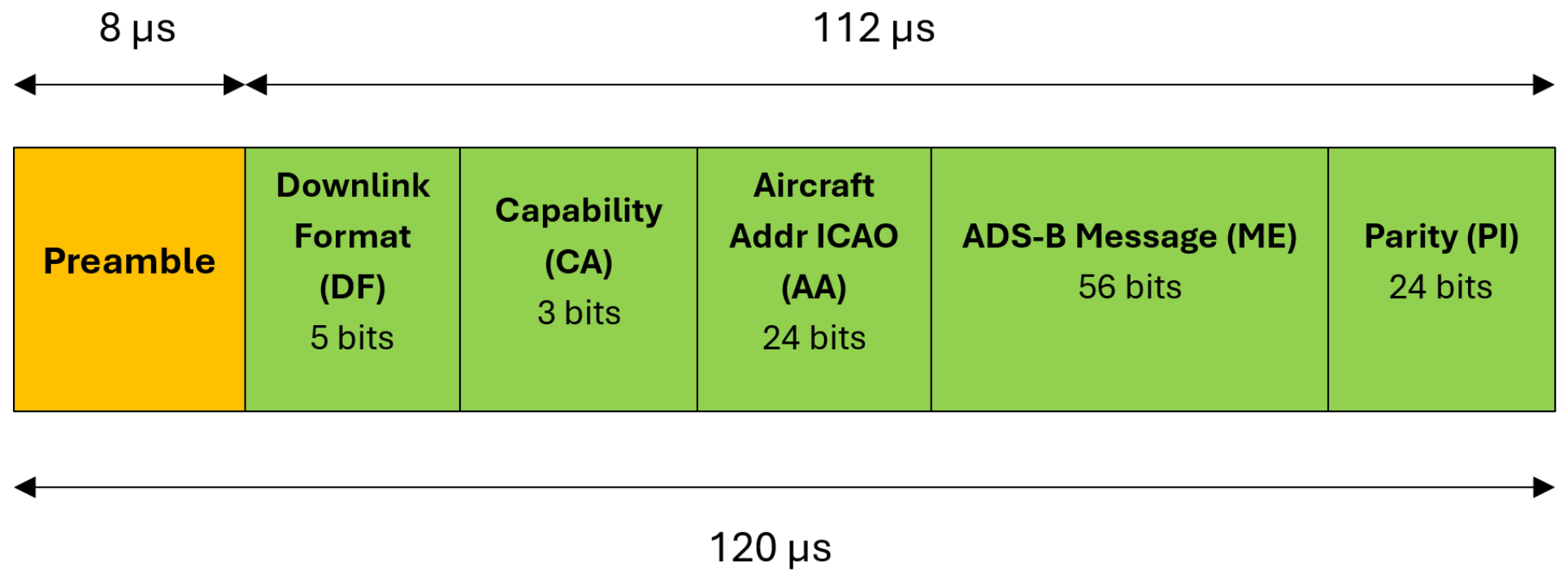
At the physical layer, an ADS-B 1090 ES transmission includes both an 8 µs preamble and a 112-bit Mode S Extended Squitter message (Figure 2). The signal uses pulse position modulation (PPM). Therefore, instead of transmitting a different frequency or phase change with each bit, PPM represents each bit as the relative location of a pulse within a specific time interval. After detecting the preamble, the receiver synchronizes timing and then samples the subsequent pulse train to recreate the original 112-bit frame [42,44].
There are many individual components that make up the ADS-B frame, including the downlink format, capability field, 24-bit International Civil Aviation Organization (ICAO) aircraft address, 56-bit message field and parity/checksum field. Most of the meaningful information regarding an aircraft is contained in the 56-bit message field. The contents of the message field depend entirely on the type code transmitted in conjunction with the ADS-B frame. Depending on which message type is used, ADS-B can transmit aircraft identification, airborne position, altitude, velocity, vertical rate, emergency status or other data derived from an aircraft [42,44].
Practically speaking, a typical 1.09 GHz receiver selects the ADS-B band from the input RF front-end, amplifies and filters the pulses received from the RF front-end, then either converts the RF signal into baseband/IQ samples or detects the envelope of the RF signal using an amplitude/logarithmic front-end. Afterward, the digital processing stage searches for the ADS-B preamble and validates the pulse positions, checks the parity field, extracts the ICAO address and message type and decodes the state parameters of the aircraft. As such, ADS-B receiver performance relies not only on how sensitive the RF portion of the receiver is but also on preamble detection, timing accuracy, packet validation and robustness against weak signals or overlapping signals [42,43].
One of the limitations of ADS-B 1090ES is that it operates in a completely open and shared surveillance environment over the 1.03/1.09 GHz surveillance bands. Aircraft transmit periodically. But transmissions are not coordinated between aircraft. Therefore, overlapped packets/garbled messages/FRUIT interference/congestion and/or loss of transmission can occur, especially in dense traffic scenarios and space-based reception scenarios. Ceballos-Gutierrez et al. [43] have shown that cooperative surveillance systems rely on repeated transactions between an aircraft and ground stations in these channels. So, therefore, these channels are under increasing pressure due to their use for cooperative surveillance.

3. Software-Defined Radio Platforms Comparison

A software-defined radio is a radio communication system in which signal processing tasks that were once hardwired into dedicated circuits are instead executed by software on a computer or programmable device. This approach makes the radio highly adaptable since new waveforms, frequency ranges, and communication standards can be supported by reconfiguring software rather than replacing hardware. SDRs cover a wide range of capabilities, and each of the well-known devices reflects a different balance between performance, flexibility, and cost [41,45]. SDR platforms used in the experimental setup follow a flexible RF front-end and digital baseband architecture, in which the received signal is first amplified, filtered, frequency-translated, and digitized, while subsequent demodulation, synchronization, decoding, and signal-quality analysis are performed in software.

3.1. USRP B200mini

The USRP B200mini, produced by Ettus Research (Ettus Research, Austin, TX, USA) offers a 1 × 1 SDR on a business card-sized board, built using the AD9364 RFIC and a Xilinx Spartan-6 XC6SLX75 FPGA [46]. The USRP B200mini is designed to be as small and light as possible while still providing excellent performance. As such it can provide 56 MHz of instantaneous bandwidth. Additionally, it can operate over a wide range of frequencies (from 70 MHz to 6 GHz). Finally, since it is bus-powered by USB 3.0, there are no external power supplies required for operation. It also includes GNU radio support through the use of the USRP Hardware Driver (UHD).
The AD9364 is the single-channel version of the AD9361 family of chips and thus retains most of the same architecture [47]. Specifically, both are based upon a direct conversion transceiver. A 12-bit analog-to-digital converter (ADC) that can run at up to 61.44 MSPS is included. When operating at the 2 MSPS operating point used during this campaign, the FPGA will perform digital decimation from the ADC’s native clock rate to effectively reduce the noise bandwidth below that of the full ADC bandwidth, resulting in a reduced noise floor. The Spartan-6 FPGA handles decimation filtering, the UHD firmware interface and sample framing before forwarding data to the host over USB 3.0.
The B200mini’s receive chain is single-channel only: unlike the B210, which has two complete AD9361 paths, the AD9364 on the B200mini provides a single half-duplex switch between a dedicated RX port (RX2) and a shared RX/TX port (RX1/TX1). For this experiment the antenna was connected to RX2, which provides the best isolation from the transmit path and the lowest noise figure. One hardware characteristic that distinguishes the B200mini from the PlutoSDR despite both using 12-bit AD936x RFICs is the clock reference quality. The B200mini incorporates a VCTCXO (voltage-controlled temperature-compensated crystal oscillator) with a factory-calibrated frequency accuracy of approximately ±2 ppm, significantly better than the uncompensated 28.8 MHz crystal used in the RTL2832U-based DXPatrol.

3.2. USRP B210

The USRP B210, produced by Ettus Research (Ettus Research, Austin, TX, USA) is a fully integrated, dual-channel transceiver platform powered by the AD9361 RFIC, allowing for coherent 2x2 MIMO operation. Like the B200mini, it uses a Xilinx Spartan-6 FPGA and USB 3.0 connectivity [48]. Its primary advantage is the ability to stream two independent receive and transmit channels simultaneously across a 70 MHz to 6 GHz range. The AD9361 is functionally equivalent to the AD9364 in single-channel operation, sharing the same 12-bit ADC architecture, noise figure specification and gain range [49]. When only a single channel is activated, as in the present ADS-B campaign, the UHD driver still initializes both RF paths internally, which introduces a marginally higher initialization overhead and DMA allocation compared to the single-channel B200mini. From a frequency stability standpoint, both B-series USRP devices rely on the AD9361/AD9364’s internal voltage-controlled crystal oscillator (VCXO), which is calibrated at the factory but is not temperature-compensated at the level of a dedicated TCXO. As the measurements analyzed in the current paper were performed for short time intervals, frequency drift will not significantly affect ADS-B decoding performance.
Although the physical configuration of the B210 differs from that of the B200mini (it is a full-sized desktop device with SMA connectors located on the front panel for both transmit/receive and receive antenna pairs), it is designed specifically for long-term fixed installations due to its ability to operate using a separate USB 3.0 connection. In order to allow for direct comparison of measurement results obtained using each device, the receive antenna pair for channel “A” was connected to the RX2 connector on the B210. The device arguments and gain settings used to initialize USRP B210 were identical to those used to initialize the single receiver path on the B200mini.

3.3. DX-Patrol MK4

A portable, affordable SDR receiver, the DX Patrol MK4, produced by Gadgetpriority-Electronics (Gadgetpriority-Electronics Unip. Lda, Óbidos, Portugal) is based on the RTL2832U Demodulation IC that was created for DVB-T TV broadcasting using the R820T2 Tuner [50,51]. The Amateur Radio Community has used its capabilities to utilize this product as a wide-band, general-purpose Spectrum Receiver via USB to output raw IQ samples.
The R820T2 tuner can capture frequencies from approximately 24 MHz to 1766 MHZ. This tuner also contains a programmable gain path containing a low-noise amplifier (LNA), mixer, and variable gain amplifier (VGA). The total gain capability of this tuner is approximately 45 dB. The RTL2832U demodulation chip contains an 8-bit ADC that operates at speeds of up to 3.2 MSPS. However, due to stability issues, most users will operate at speeds of 2.4 MSPS. The limitation of this type of chip is the amount of resolution it has available.
The DXPatrol MK4 connects to the host computer via USB 2.0 and is supported in GNU Radio through the SoapySDR abstraction layer (driver=rtlsdr). Because the RTL2832U operates at a native sample rate that does not include 2.000 MSPS exactly, a Rational Resampler block (interpolation 125, decimation 128) is required in the GNU Radio flowgraph to convert the 2.048 MSPS output of the SDR source to the 2.000 MSPS required by the ADS-B Framer and Demodulator blocks.
From a signal-chain perspective, the RTL2832U implements a direct-conversion (zero-IF) architecture. The R820T2 downconverts the 1.09 GHz input to baseband using an internal PLL-controlled local oscillator referenced to a 28.8 MHz crystal. The resulting baseband I/Q signal is then digitized by the on-chip 8-bit ADC. One of the most significant practical limitations of this architecture in a dense urban RF environment is the susceptibility to IQ imbalance and DC offset [52], both of which are inherent to direct-conversion receivers and are not corrected in hardware on the RTL2832U. These impairments appear as a spectral peak at DC and opposite-phase image peaks of interference that can mask weak ADS-B pulses even if the ADS-B carrier frequency is clear.
The above limitations notwithstanding, the DXPatrol MK4 is widely employed in amateur ADS-B reception configurations due to the extremely low price point of this product and widespread availability. For example, under conditions with limited levels of interferers (such as rural or semi-rural environments away from cell towers), RTL-SDR-based ADS-B receivers are able to obtain reasonable ADS-B reception quality. However, regardless of ADS-B receiver setup, the fundamental limitation will always be ADC resolution.

3.4. Adalm-Pluto

Designed by Analog Devices (Analog Devices, Wilmington, MA, USA), the Adalm-Pluto is a learning module intended for students and hobbyists. It is powered by the AD9363 highly integrated RF Agile Transceiver and a Xilinx Zynq-7010 FPGA (SoC) [53]. While its factory specifications state a range of 325 MHz to 3.8 GHz, the firmware can be unlocked to match the AD9364 specifications: 70 MHz to 6 GHz [54]. It provides one transmit and one receive channel in full duplex. The 12-bit ADC offers approximately 72 dB of theoretical dynamic range, a significant improvement over the 8-bit RTL-based devices. The Adalm-Pluto connects to the host via USB 2.0 and is supported in GNU Radio through the gr-iio module. The AD9363 transceiver integrates a complete RF front-end, including a wideband synthesizer, matched filter, analog-to-digital and digital-to-analog converters, and digital signal processing for gain control, DC offset correction and IQ imbalance compensation [55]. The on-chip automatic gain control (AGC) loop can be configured in slow-attack, fast-attack or manual modes. For ADS-B reception, manual gain control is preferred because AGC, if configured with insufficient attack speed, may not settle within the brief 120 µs window of an Extended Squitter message, introducing gain-dependent amplitude distortion that impairs preamble detection. In comparison to the UHD driver used by the USRP platforms, the libiio driver stack, which represents the communication layer to the AD9363 using the Industrial I/O (IIO) kernel framework, introduces a lower amount of per-buffer latency compared to the UHD driver stack, reducing, as such, the likelihood of sample loss/drops for moderate sampling rates.
The AD9363 supports a nominal frequency band from 325 MHz up to 3.8 GHz and has a maximum instantaneous bandwidth of 20 MHz along with a maximum gain of about 71 dB when the firmware is unlocked to utilize the full specification of the AD9364.
For ADS-B receiver operation at 1.09 GHz, the existing gain range for the AD9363 (66 dB or 5 dB below its maximum value) is entirely sufficient. The signal strength from an airplane antenna located on a rooftop is usually somewhere between −80 and −50 dBm for airplanes in the 50–200 NM range. Thus, adding an additional 66 dB gain via the AD9363 results in the antenna signal being well beyond the ADC’s noise floor while also avoiding saturation. A practical consideration specific to the PlutoSDR in this campaign is the network interface: the device enumerates on the host as a USB network adapter (RNDIS/ECM) with the IP address 192.168.2.1, which means all IQ data travels over a TCP/IP stack rather than a direct USB bulk transfer as in the USRP devices. The gr-iio PlutoSDR Source block abstracts this entirely, but the extra network protocol overhead introduces a slightly higher and less deterministic per-packet latency than a native USB bulk transfer. At 2 MSPS this latency is not problematic, but it would become a limiting factor at sample rates above approximately 30 MSPS.

3.5. Comparative Analysis of SDR Platforms

There is an array of differences (as listed in Table 2) concerning ADS-B reception, which are evident based upon the specifications.
One of the most important distinctions among the four options is ADC resolution; while the DXPatrol MK4 has an ADC resolution of 8 bits (providing nearly 48 dB of theoretical dynamic range), the three AD936x-based platforms have 12-bit ADC resolutions providing almost 72 dB of dynamic range, representing a difference of approximately 24 dB. As far as these differences are concerned within a real-world receive chain, this represents a direct impact on sensitivity in the presence of co-channel and adjacent channel interference. Another distinction among the four options is the host interface. While the DXPatrol MK4 and Adalm-Pluto utilize USB 2.0 (which would provide sufficient bandwidth for their 2-MSPS operation points) and thus introduce greater CPU overhead per transfer when compared to USB 3.0, the two USRP platforms use USB 3.0 (thus reducing DMA latency and the likelihood of sample buffer underflow at the host side). A third important consideration involves the availability of onboard signal processing. While there is hardware DC-offset correction and I/Q-imbalance compensation implemented by the AD936x family, neither of these calibration loops is found in the RTL2832U. Calibration loops are especially important in direct conversion architectures where DC-leakage and I/Q-phase-mismatch are inherent characteristics of the mixer architecture, and can generate spectral artifacts that can interfere with ADS-B preamble detection.

4. Measurement Setup and Software Implementation

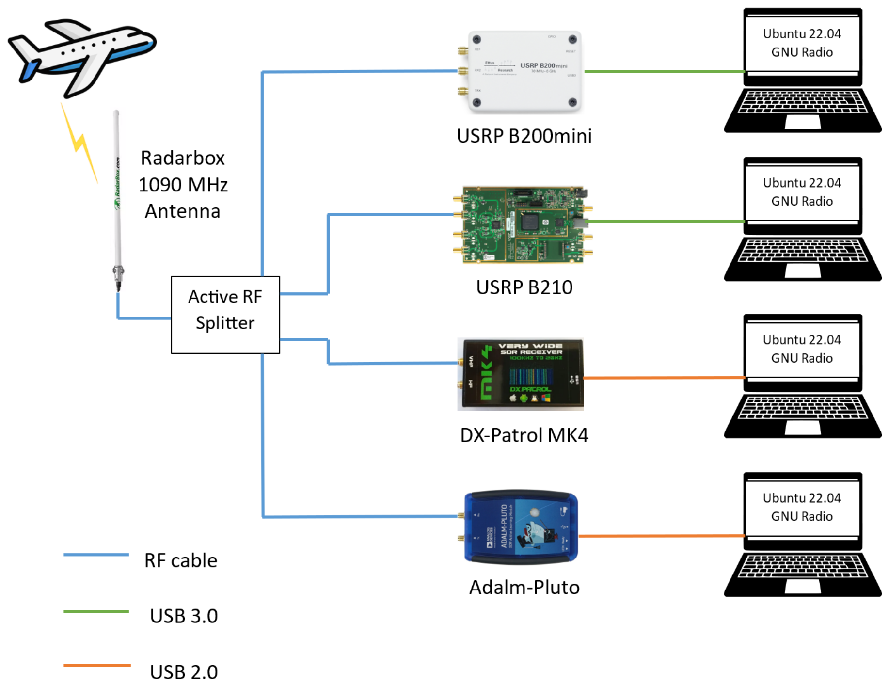
This section presents the experimental setup and the comparative measurement results obtained by running the same ADS-B reception chain on four SDR platforms in parallel: the DXPatrol MK4, the Adalm-Pluto (PlutoSDR), the USRP B200mini and the USRP B210. All four receivers are connected simultaneously to a single antenna through an active RF power splitter, whose internal amplifier compensates for the intrinsic division loss of the network.

4.1. Measurement Setup

The first element of the signal path within the receiving section (Figure 3) is the Radar Box 1.09 GHz Omni-Directional Antenna that is located at the window ledge of a northward-facing room on the 3rd floor of the Faculty of Electronics, Telecommunications and Information Technology (ETTI) building, situated in Bucharest, Romania (approximately 15 m elevation above ground and 100 m elevation above sea level).
The antenna is specifically designed as a vertically polarized collinear array for the 1.09 GHz ADS-B band and has a nominal value of 5.5 dB for its gain; it also has an omni-directional azimuth radiation pattern, a vertical beam width of around 15° and a 50 Ω N-Type connection on its base. By using a collinear approach to arrange elements, this design allows the user to achieve a gain compared to a standard half-wave dipole, while maintaining full 360° azimuth coverage so as to be able to detect planes from every direction without having to physically move the antenna. The antenna was attached to a magnetic mounting base that sits on top of the surface. The radiating portion of the antenna was strictly oriented vertically. The position of the installation provides clear lines of sight to most of the sky above Bucharest. At the typical operating altitude range of ADS-B, commercial aircraft cruise at 8000–12,000 m, which corresponds to line-of-sight distances of 300–450 km at near-zero elevation. The antenna is connected via an RG-58 coaxial cable of approximately 3–4 m length (SMA connectors) to the input port of the active RF power splitter. RG-58 introduces approximately 0.5 dB of insertion loss per meter at 1 GHz, which means the cable introduces a total attenuation of roughly 1.5–2 dB between the antenna and the splitter input.
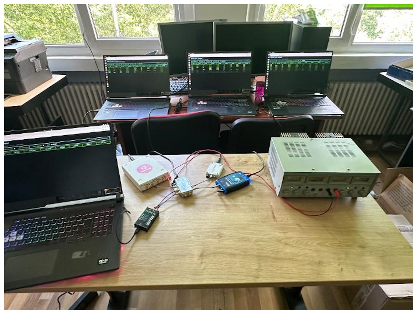
The signal is then distributed through an active RF power splitter providing up to seven output ports, of which four were used in the present campaign. A passive N-way power splitter introduces an intrinsic division loss of 10 log10(N) dB, approximately 6 dB for a 4-way split, which would significantly degrade the SNR at each SDR input. To compensate for this, the splitter used here incorporates a broadband internal amplifier powered by an external DC supply. The amplifier gain is calibrated to restore the signal level at each output to approximately the same level as the antenna input, with identical gain at all ports. This means the comparison between SDR platforms is not biased by different signal levels at different receiver inputs: the only variable is the SDR hardware and driver stack itself. Prior to the comparative measurement campaign, the four splitter outputs used in the experiments were experimentally checked at 1.09 GHz under the same input conditions. The received power levels at the four ports were compared using the same cable and connection configuration employed during the subsequent measurements. The observed port-to-port differences were sufficiently small relative to the performance differences investigated in this work, confirming that the RF distribution network did not introduce a significant systematic bias between the SDR inputs. Following this verification, each active output port is connected through a short SMA coaxial pigtail (under 15 cm) directly to the RF input of one of the SDR platforms. The complete RF distribution setup is shown in Figure 4.
The receiver gain was set for each SDR platform at 5 dB below the maximum available gain. This approach was empirically found to maximize the number of received ADS-B packets, while minimizing the potential for ADC saturation or front-end compression. The resulting receiver gain settings were 40 dB for the DXPatrol MK4, 66 dB for the ADALM-Pluto and 71 dB for the two USRP platforms.
Each of the four SDR platforms was connected to its own host computer. Four identical ASUS Rog Strix G713IM laptops were used as host computers (AMD Ryzen 7 4800 h processor, 16 GB RAM, GeForce RTX 3060), running Ubuntu 22.04.5 as operating system.
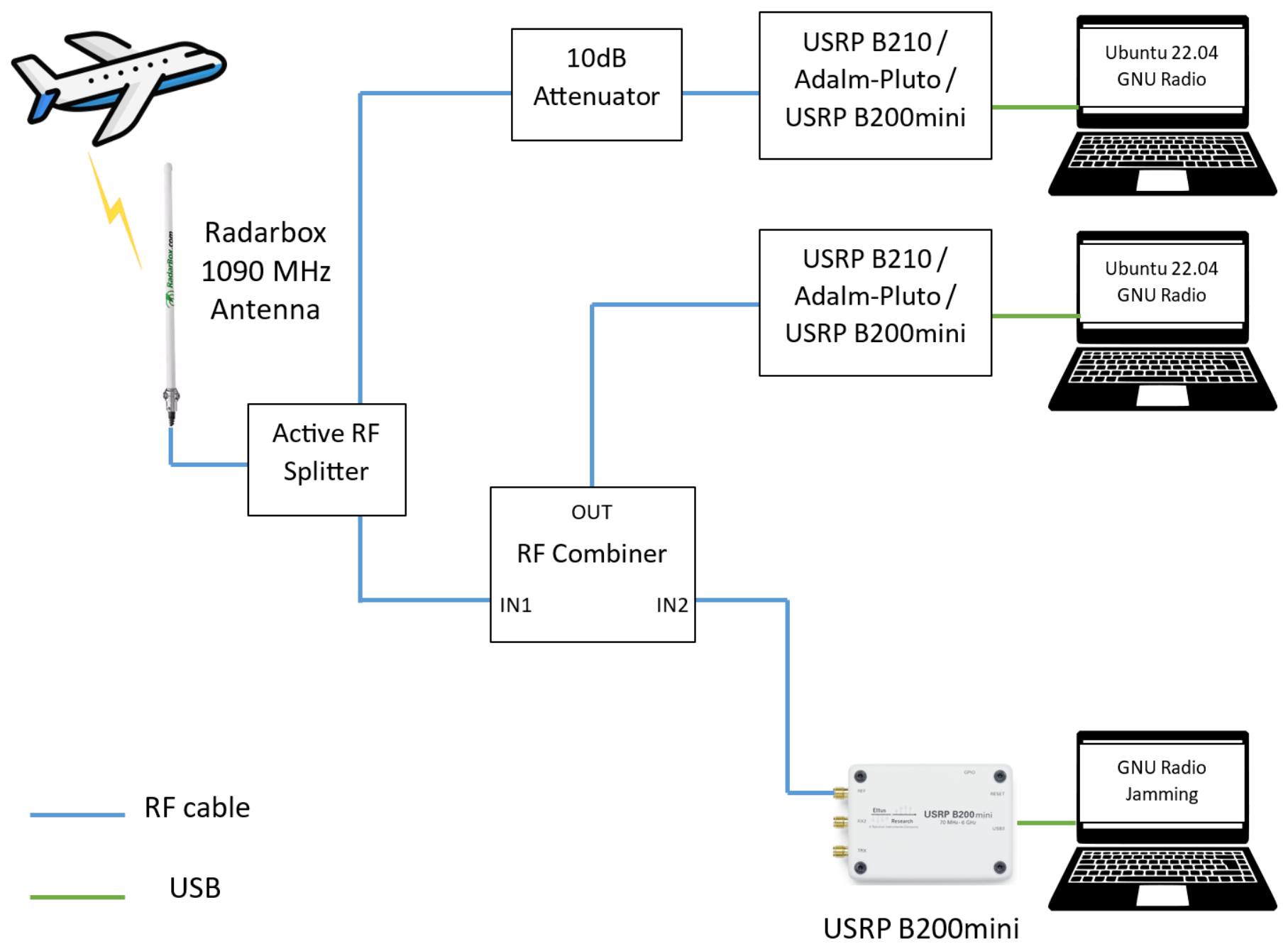
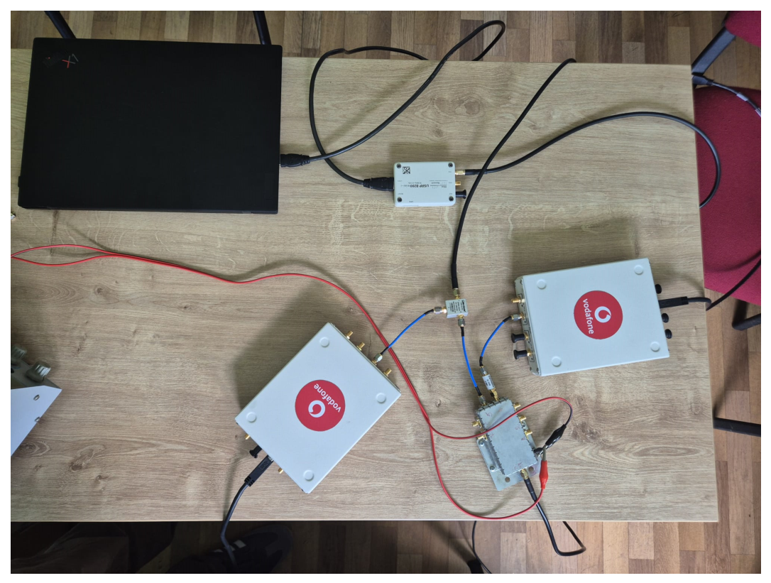
To evaluate receiver behavior under interference, a controlled in-band jamming source was added to the experimental setup. Two different approaches were used, depending on how the jamming signal was applied over the ADS-B received signals: over-the-air or using a cabled connection. For the over-the-air test, the jamming system consisted of a separate USRP B200mini connected to its own dedicated laptop, with its own dipole antenna, placed approximately 1 m away from the main RadarBox receive antenna. The jamming signal itself was generated in GNU Radio using a Gaussian Noise Source block feeding the USRP Sink’s transmit chain, centered at 1.09 GHz with a 10 MHz signal bandwidth; this produces broadband additive white Gaussian noise (AWGN) spanning the entire 1.09 GHz ADS-B reception window, rather than a narrowband single-frequency tone. Three jamming levels were used, set via the gain of the jammer’s USRP B200mini transmit chain: gain 20 dB (low, corresponding to a transmit power level of −92 dBm), gain 40 dB (medium, corresponding to a transmit power level of −72 dBm) and gain 60 dB (high, corresponding to a transmit power level of −52 dBm). The interference power levels for each gain setting were independently confirmed with a spectrum analyzer. For each of the three jamming levels, and additionally with the jammer powered off (“no jamming”), the same four-platform joint measurement was repeated under identical conditions otherwise (same antenna, active splitter, GNU Radio flow-graph, gain settings per platform, approximately 10 min session duration). A second jamming configuration, in which the interference is injected directly into the RF signal path via a cable combiner rather than radiated over the air, was also implemented as part of this work (Figure 5). This cable-coupled setup uses two identical SDR units in parallel (in the experiments, either USRP B210, Adalm Pluto, or USRP B200 mini will be used), one connected directly to the main antenna splitter (the “clean” branch) and one connected through a secondary splitter that combines the antenna signal with a controlled noise source over a cable path (the “noisy” branch).
In Figure 6, the experimental setup for the USRP B210 receiver is shown. The two USRP B210 units were operated in parallel, both fed from the same main antenna splitter, but along two different paths. The first unit (the clean branch) is connected directly to the main splitter through a fixed 10 dB attenuator, included specifically to equalize the insertion loss introduced by the secondary splitter on the other branch, so that any difference in performance between the two units reflects the presence of jamming rather than a systematic power imbalance between the two paths. The second unit (the noisy branch) is connected to a secondary splitter that combines the antenna feed with a noise signal injected over a coaxial cable from a separate USRP B200mini and dedicated laptop, the same jamming hardware as discussed in the preceding sections, but here coupled on-wire instead of radiated. Similar setups to the one shown in Figure 6 are obtained using pairs of Adalm Pluto or USRP B200 mini receivers.

4.2. Software Implementation

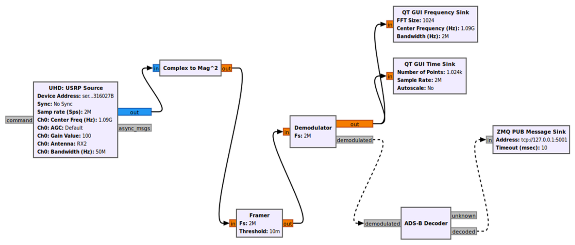
All four platforms share an identical downstream processing chain implemented in GNU Radio, an open-source software development toolkit that provides signal processing blocks, which can be connected into flowgraphs, allowing the construction of complete radio systems in software. The flowgraph for this project (Figure 7) was designed in GNU Radio Companion (GRC), a graphical interface that generates a Python script from the block diagram. The generated script is then executed directly on the host laptop to run the reception chain in real time. The signal-processing pipeline, from ADC samples to fully decoded and published ADS-B messages, consists of six functional stages: SDR source, magnitude conversion, preamble framing, PPM demodulation, ADS-B decoding and message publication. Each stage is described in detail below, along with the per-platform differences in the source block configuration. For the four different SDR platforms, different drivers were used for allowing the capture of the RF samples: UHD for the two USRP platforms, libiio for the Adalm-Pluto platform and SoapySDR for the DXPatrol MK4 platform.
The four flowgraphs, corresponding to the four different SDR platforms used, were started in a staggered manner, allowing them to stabilize for approximately 30 s, after which the logging scripts on all four identical laptops were started simultaneously through a verbal countdown. Each session was labeled and ran continuously for approximately 10 min. At the end of each session, the logging script automatically wrote a JSON metadata file containing the total number of decoded messages, the number of messages carrying a valid position or callsign, the number of unique ICAO addresses observed and the effective messages-per-minute rate.
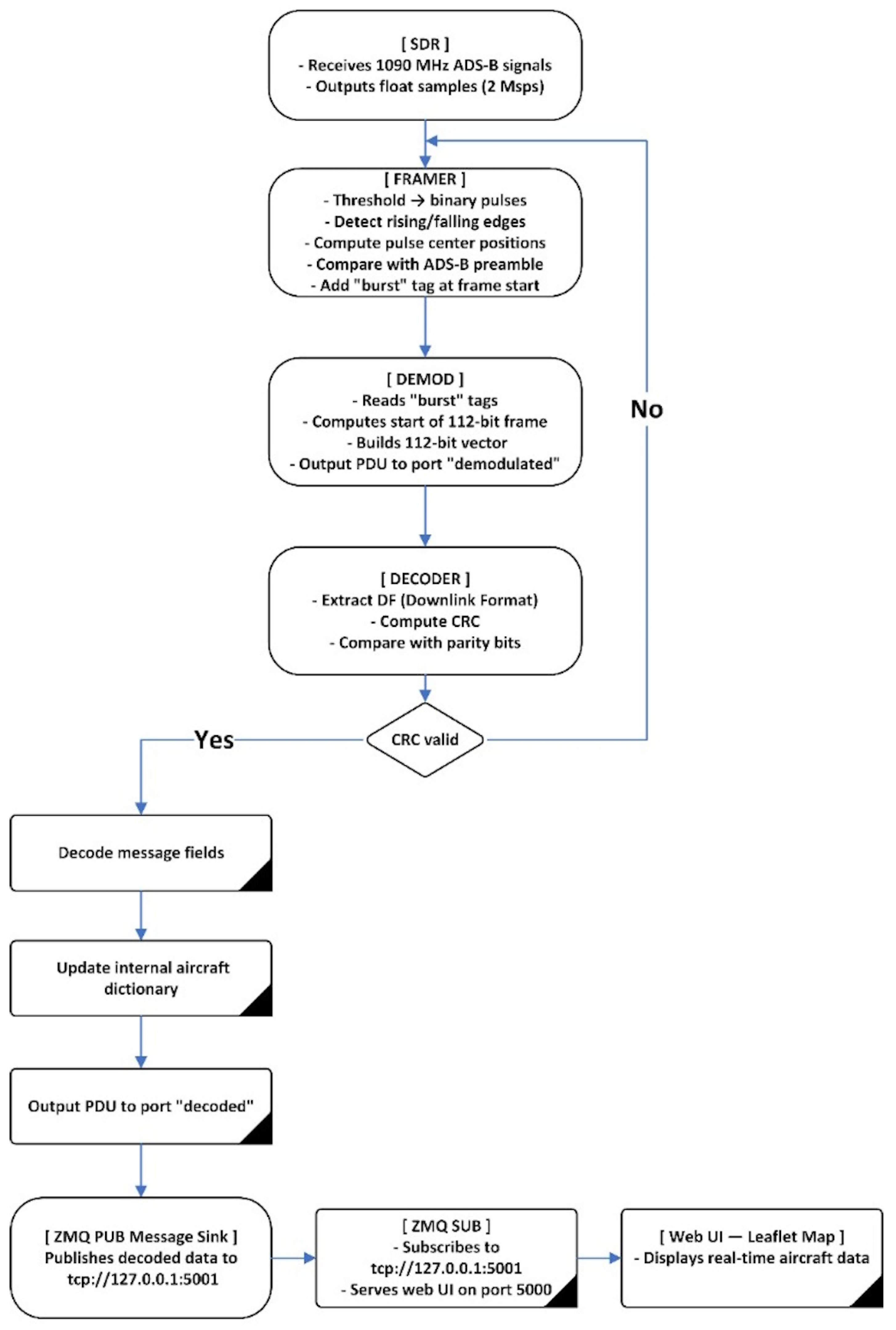
Figure 8 shows a logic software diagram of the proposed ADS-B signal processing chain, which is detailed in the following paragraphs.
All four receivers were tuned to 1.09 GHz with a 2 MSPS sample rate and a Framer detection threshold of 0.001. The choice of a 5 dB margin from the maximum gain deserves further justification. In an urban RF environment, such as the ETTI building, strong out-of-band signals from GSM-900, LTE-1800 and Wi-Fi transmitters are present at the antenna port. Although these signals are nominally outside the 2 MHz receive bandwidth centered on 1090 MHz, the wide-open front-end of each SDR allows them to reach the ADC. Operating at maximum gain risks saturating the ADC on these interferers even when the ADS-B signals themselves are within the linear range. A 5 dB back-off from max gain therefore provides a reasonable balance: sufficient sensitivity to detect distant airplanes while providing sufficient margin above the strongest local interference so that it does not cause clipping. A Framer detection threshold was set to 0.001 for all receiver chains and was selected during preliminary testing to provide a suitable balance between false preamble candidates and missed weak pulses. Since the numerical amplitude scaling at the output of the SDR source may differ between UHD, IIO and SoapySDR, this value is treated as a common DSP-domain setting rather than as an equivalent calibrated RF sensitivity threshold for all platforms. The reported comparison therefore reflects the complete SDR/driver receiver chain under the same downstream processing configuration. The fixed threshold is applied during the initial pulse-detection stage, while subsequent preamble validation and PPM bit decisions are based on relative amplitude comparisons.
During the experiments, which will be presented and analyzed in the subsequent section, the resources of the host computers that were used for the four SDR platforms were monitored. For all the SDR platforms, the memory consumption during the experiments was between 17% and 18%. Regarding the processor load, in the case of the Soapy SDR and libiio, the load was below 30%, whereas in the case of the UHD, the load sometimes exceeded 50% for some of the processor cores, but did not exceed 70% during any of the tests.
The primary responsibility of the Framer block is to recognize the preamble in the ADS-B data stream and label the onset of every frame so that subsequent blocks are able to obtain the payload. The block processes the input signal and labels the location of the first valid data block based on the presence of the preamble. Two major parameters define how the Framer block operates: the sampling frequency (fs) and the detection threshold. The 2 MSPS sampling rate was selected considering the 1 Mbps ADS-B symbol rate, providing two samples per symbol. A sampling rate of 2 MSPS was selected considering the 1 Mbps ADS-B bit rate, providing two samples per ADS-B bit.
At the first processing stage, the sampled magnitude-squared signal is converted into a binary pulse representation using the predefined detection threshold. Each sample with an amplitude equal to or greater than the threshold is assigned a value of 1, while the remaining samples are assigned a value of 0. This binary sequence is used for pulse detection and does not represent the decoded ADS-B data bits. By comparing consecutive binary samples, the Framer identifies rising transitions from 0 to 1 and falling transitions from 1 to 0. The sample indices of the corresponding rising and falling edges are then averaged to estimate the position of each detected pulse. These pulse positions are used as candidates for the subsequent ADS-B preamble detection stage.
For each detected pulse candidate, the Framer examines the following 16 samples, corresponding to the 8 µs ADS-B preamble at 2 MSPS. The amplitude of the candidate pulse is used as a local reference, and samples exceeding one half of this value are classified as pulses. The resulting 16-sample binary pattern is then compared with the known ADS-B preamble pattern. Only when the complete pattern matches the expected preamble is the corresponding sample position tagged as the beginning of an ADS-B frame. Thus, the fixed detection threshold is used to locate the initial pulse candidates, while the subsequent preamble validation uses a threshold relative to the candidate amplitude.
Upon successful identification of a preamble, the Framer block will ignore all subsequent pulses occurring during the expected length of a message (112 bits), to prevent false triggers within the same frame.
In order to ensure signal continuity between successive data buffers, the Framer block employs the set-history function provided by GNU Radio to keep track of all samples corresponding to the preamble length. This ensures that even though preambles can potentially commence at nearly any point along a buffer boundary, they are still properly detected across multiple frames.
Real-time operation is important for efficiency and reliability reasons. All parts of its algorithm were designed with speed and low latency in mind. The algorithm achieves this goal by employing constant thresholds for pulse detection, performing difference calculations for edge detection, and averaging for estimating symbol positions.
The Demodulator Block in the ADS-B Receiver Chain converts a received signal into a string of usable bits that represent the content of an actual message. The Demodulator Block receives processed signals from the Framer Block containing tags placed upon them to indicate the start of an ADS-B message. One of its first tasks is to locate these tags and establish what positions in the received signal contain sequences of bits that make up an actual message. The tags are indicators placed by the Framer Block and tell us where each message begins and ends within a continuing flow of samples.
As a second step toward extracting tags located within areas of interest in the signal, the demodulator uses the g e t _ t a g s _ i n _ r a n g e () function. Tags extracted via this method give us sufficient reference points to find each message in terms of where each message starts and stops within the continuing stream of samples.
At the completion of the detection of a tag, the Demodulator computes the precise start and stop locations of the segment of the signal containing the data. The start and stop locations of the segment of the signal containing the data are found relative to the tag offset and the number of samples per symbol. An accurate computation of the start and stop locations of the segment of the signal containing the data assures that the demodulator processes only that part of the signal containing the message (as opposed to non-useful data or noise).
As the ADS-B signal travels through successive blocks of processing, every block may alter some aspects of the data stream, thus shifting the apparent location of the useful information. To compensate for this, the demodulator adjusts its internal references based upon what percentage of the original data it has already processed. This adjustment ensures that the demodulator accurately finds the start and end of each message and focuses solely on those parts of the signal that contain the actual message, while excluding extraneous noise or unrelated data that could corrupt the accuracy of decoding.
Prior to performing any demodulation operations, the demodulator checks whether the complete segment of useful signal is contained entirely within the present block of samples. This check is required to avoid truncation during partial processing of a message, which would cause either data loss or incorrect decoding. This assurance confirms that the last position of the useful signal falls within the bounds of the current block of samples, so that the entire message is available for accurate processing.
Demodulation converts the received signal into a string of useful bits by comparing values at two pre-determined points in each symbol, one being at the start and one being at the middle point. When the value at the beginning is greater than that at the middle point, it is assigned a 1; otherwise, it is assigned a 0. Since comparisons are made using fixed points within each symbol, regardless of any changes or noise that may have occurred during transmission, this method provides a reliable means to derive transmitted data.
ADS-B Decoder block is responsible for parsing ADS-B messages and validating their integrity using cyclic redundancy checking with CRC (Cyclic Redundancy Check). Initialization for this block requires configuration of several parameters and establishment of an internal representation to facilitate message processing. In addition, initialization includes defining a CRC polynomial that is specific to ADS-B messages and creation of a lookup table for CRC results.
The ADS-B Decoder block receives packets that have been demodulated through a message port. These packets comprise binary data that must be parsed to extract meaningful information. The initial step in parsing a packet is to clear any remaining data from previous packets and reinitialize variables used to hold decoded information. Resetting internal variables prevents carry-over effects due to previous packets. It ensures each packet is processed independently and accurately.
Following reset, the block retrieves data from packets and begins to parse packet headers. The header is common to all ADS-B messages and includes the downlink format (DF), which specifies types/structures of messages. Parsing headers involves extraction and interpretation of the first bits in the messages to determine their format/content. This step is critical because different DFs correspond to different formats/content of messages, and proper header parsing ensures the remainder of the message is properly interpreted.
Parity is checked using the previously calculated CRC. Successful parity checking determines whether the block continues to decode the remainder of the message; failure leads to the rejection and discarding of message.
Upon successful parity checking, the ADS-B Decoder block continues with decoding the content of the message. Content includes various fields extracted/interpreted from ADS-B messages (e.g., ICAO identifier/address, altitude/speed/heading/position [latitude/longitude]). Message decoding depends upon message type identified by DF (downlink format)/TC (type code), and appropriate algorithm(s) are utilized to ensure accurate interpretation/conversion to usable form. For instance, in aircraft identification messages, extracted/decoded ICAO code/call-sign are utilized.
The information extracted from a message is used to update an internal dictionary describing each received aircraft. Dictionary entries include latest position/speed/altitude/etc. The data block also contains speed information as two component values representing east/west and north/south speeds/signs determining directions of movement. Total speed is derived by summing these components, while direction-of-travel is established similarly. Vertical rate (ascending/descending speed) is also extracted/interpreted based upon a sign indicating whether an aircraft is climbing/descending.
The data dictionary is updated after each aircraft’s message has been decoded. Valid data are published through the “decoded” port; invalid data are published through the “unknown” port. Additionally, valid/invalid data can be displayed on-screen for real-time observation.
One key function provided by the ADS-B Decoder Block is accurate derivation of an aircraft’s position from an ADS-B signal. An aircraft’s position is communicated through Compact Position Reporting (CPR), a method for transmitting positional data that encodes latitude/longitude across two separate frames: one even and one odd. Proper derivation of these frames permits accurate computation of geographical position.
CPR is a compact position reporting method that compresses positional data into a compact format. Two consecutive frames contain an aircraft’s position: one even frame and one odd frame, each having 17-bit encoded latitude/longitude values.
Latitude/longitude CPR values are individually interpreted. The fractional value for the latitude CPR value is computed by dividing the CPR latitude value by 131,072; the same operation is applied for the longitude CPR value. Latitude Index (j) is computed using CPR-specific equations taking into consideration differences between even and odd frames. Longitude Values are computed using j calculated above, combined with CPR values received earlier. Functions are employed to compute the number of longitude zones applicable to the current latitude value, providing accurate longitudinal position. Both latitude and longitude values are adjusted in this step so that final values lie within correct ranges (geographical latitudes/longitudes).
Altitude transmitted in ADS-B signals is encoded in a specific manner with an indication of units of measure embedded in an extra parity bit referred to as Q-bit. There are two basic altitude encoding methods. If Q-bit equals 0, altitude is encoded in 100-foot intervals; direct interpretation of altitude bits does not require any additional adjustments. If Q-bit = 1, altitude is encoded in 25-foot intervals; prior removal of Q-bit from the bit sequence occurs before direct interpretation for computing altitude in feet. The resulting value is then multiplied by 25 plus base offset to yield actual altitude value.
Speed information transmitted in the data block consists of two sets of values corresponding to east–west and north–south components along with signs indicating direction of motion. Speed-total value is calculated using vector-addition combination of these two-component speed values; direction of movement value is derived similarly. Vertical rate (rate at which altitude is changing) is also extracted/interpreted based upon the sign indicating whether an aircraft is climbing or descending.
After successfully decoding the extracted data, the ZMQ PUB Message Sink block broadcasts it to the TCP address “tcp://127.0.0.1:5001”, allowing web-server access to broadcasted data.
Upon accessing http://localhost:5000 a web -server displays content with an interactive map created utilizing the Leaflet library on client side browser. Broadcasted data received from GNU Radio via port #5001 are processed by a server and used to place markers on a map showing aircraft position and associated info (call-sign/altitude/speed). The user may view/interact with this info on a map in real time.

5. Results and Discussion

This section reports on receiver performance metrics, such as total decoded message count, unique aircraft tracked, position decode rate and effective message rate, relating the observed differences to the architectural properties of each platform discussed in Section 3. Regarding the two different jamming experiments that we performed, it has to be mentioned that the over-the-air jamming results should primarily be interpreted as a comparative real-world campaign, whereas the cable-coupled jamming provides more controlled evidence for the direct effect of interference.
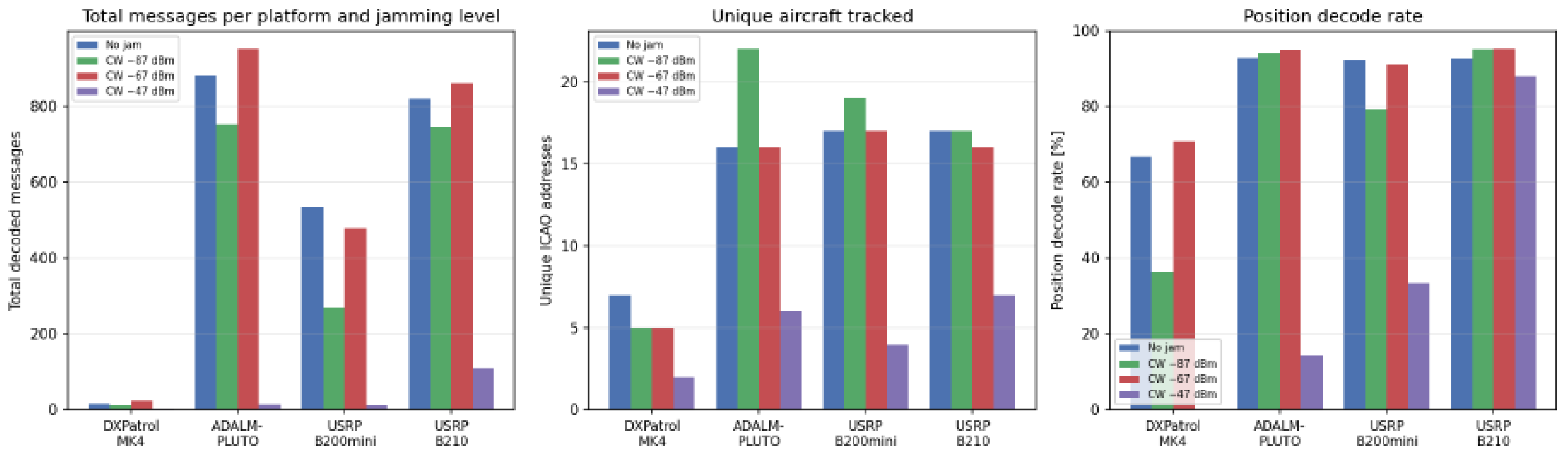
Building on the over-the-air jamming setup, the joint four-platform measurement was repeated under four conditions: no jamming and three increasing levels of over-the-air broadband Gaussian noise centered at 1.09 GHz, set via the jammer’s transmit gain (gain 20 dB, gain 40 dB and gain 60 dB respectively). The absolute transmit power levels in dBm corresponding to each of the above-mentioned jammer transmit gains (see Table 3), were evaluated using a spectrum analyzer at the output of the SDR used for transmitting the jamming signal. Each of the sixteen resulting sessions (four platforms × four jamming conditions) ran for approximately 10 min on 16 June 2026, with all four receivers connected to the same antenna through the active RF splitter, while the noise jammer operated independently and over the air. The summary statistics for all sixteen sessions are collected in Table 3.
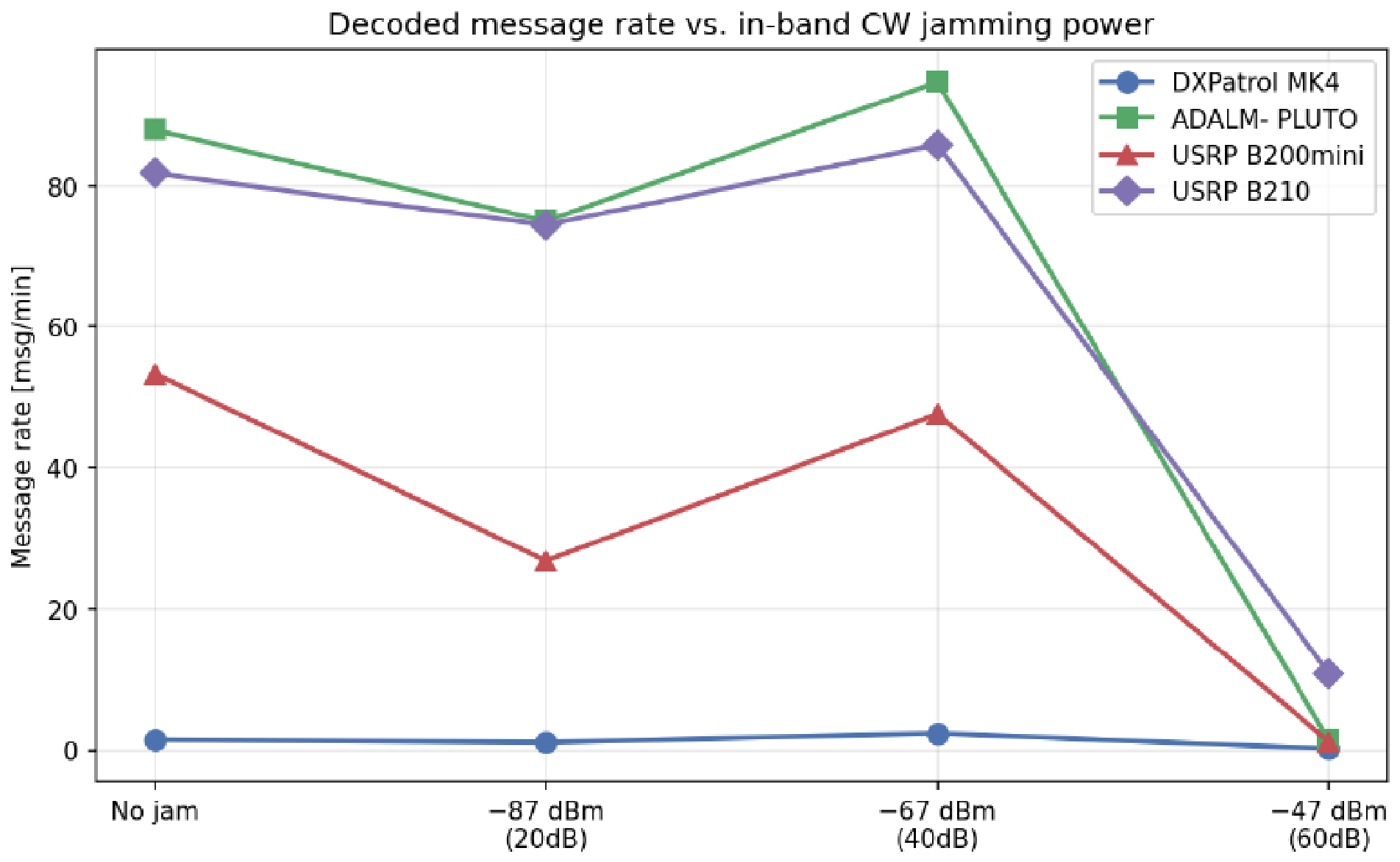
Two distinct effects are visible in Table 3 and Figure 9 and Figure 10, and it is important to separate them. The first is the familiar two-tier architectural separation: the DXPatrol MK4’s 8-bit ADC limits it to single-digit or low-double-digit message counts (2–24 messages per session) across every condition, while the three 12-bit AD936x-family platforms (Adalm-Pluto, USRP B200mini, USRP B210) decode one to two orders of magnitude more messages whenever the jammer is off or at low/medium power. As the theoretical dynamic range difference between an 8-bit and a 12-bit ADC is of 24 dB, we consider this aspect as a primary factor for the observed differences. However, secondary contributions also exist, related to the different noise figures (the AD936x family is characterized by a 3 dB NF, whereas the R820T2 has a 6 dB NF) and to the presence of the on-chip corrections (AD936x has DC offset/IQ imbalance correction, whereas RTL2832U does not). The second, more striking effect concerns how each platform responds as the jamming power increases. At gain 60 (the highest jamming power tested) every platform collapses sharply: DXPatrol MK4 falls to 2 messages (0.20 msg/min), ADALM-PLUTO to 14 messages (1.40 msg/min, a −98.4% change from its own no-jamming baseline), USRP B200mini to 12 messages (1.20 msg/min, −97.8%), and USRP B210 to 109 messages (10.86 msg/min, −86.7%). The B210 is notably the most resilient of the four at this highest jamming level, retaining roughly an order of magnitude more messages than the other three platforms and the only one of the four whose position decode rate (88.07%) remains close to its unjammed value. The fact that, for all the platforms, the receive performance seems to be better for a jamming gain of 40 dB as compared to the results obtained when the jamming gain was set to 20 dB might be related to the fact that the number and the locations of the aircraft were different during the two time intervals that were used for capturing the ADS-B signals, which might influence the obtained results. In Section 6, we suggested possible approaches for eliminating such issues in future research.
Table 4 contains a cost-performance analysis of the SDR platforms that were used, considering the results included in Table 3. The clear winner in the case of no jamming reception is the Adalm-Pluto platform, as it received a similar number of messages as compared to the USRP platforms, but at a much lower cost. In the case of the strong jamming experiment, the largest number of received messages is obtained using the USRP B210 platform; however, the cost/message is still lower for the same Adalm-Pluto platform.

5.1. Detection Range Under Over-the-Air Generated Jamming Conditions

Beyond raw message counts, the geographic position field decoded from each ADS-B message (latitude/longitude, recovered via the CPR algorithm) makes it possible to estimate, for every aircraft heard by a given platform, its distance from the receive antenna at the moment of reception. Taking the maximum such distance over all aircraft heard in a given session yields an estimate of that platform’s effective maximum detection range under the corresponding jamming condition. Distances were computed using the great-circle (haversine) formula between the antenna location (44.2601° N, 26.0327° E) and each decoded aircraft position. A small number of individual position fixes (fewer than 0.1% of all position-bearing messages across the campaign) were excluded as CPR decoding artifacts: occasional even/odd frame pairs are mismatched across two different aircraft or across a corrupted frame, producing a single spurious fix hundreds or thousands of kilometers from the rest of that aircraft’s track (for example, a single fix placed in Poland appearing in the middle of an otherwise consistent Bucharest-area track for the USRP B200mini in the no-jamming session). Any position fix deviating by more than 100 km from the median position of its own aircraft’s track within the session was treated as such an artifact and discarded. The 100 km threshold was determined considering that commercial aircraft typically move less than 50 km in 10 min at cruise speed and that CPR mismatch artifacts produce fixes hundreds or thousands of kilometers away. As such, this threshold should be large enough to retain genuine aircraft movement while removing outliers.
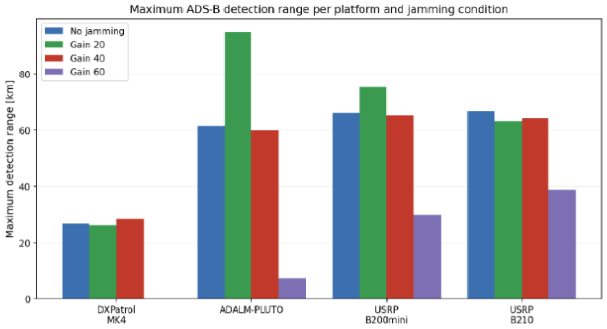
The range figures in Table 5 are consistent with, and add useful context to, the message-count results in Table 3. The DXPatrol MK4’s maximum range stays confined to roughly 26–28 km across the conditions where it decoded any position-bearing messages at all, a radius small enough to be dominated by a handful of nearby high-SNR aircraft rather than by genuine long-range sensitivity; this is consistent with its 8-bit ADC limiting it to only the strongest, closest signals even in the absence of jamming. The three 12-bit platforms, by contrast, reach maximum ranges between roughly 60 and 95 km under no jamming and moderate jamming, more than double the DXPatrol’s radius, directly reflecting their higher dynamic range and correspondingly lower effective sensitivity floor. These maximum ranges are plotted per platform and jamming condition in Figure 11.
At the highest jamming level (gain 60), the maximum range collapses for every platform, but by very different margins: Adalm-Pluto’s range drops to just 7.2 km (a single aircraft, an order of magnitude below its unjammed range), USRP B200mini’s drops to 29.9 km (roughly 55% of its unjammed range), while USRP B210 retains 38.9 km (roughly 58% of its unjammed range and the largest absolute range of any platform at this jamming level). This range-based view reinforces the message-count finding that the USRP B210 is the most resilient of the three 12-bit platforms under severe in-band interference: not only does it decode more total messages at gain 60, it also continues to hear aircraft at meaningfully greater distances, where the received signal is necessarily weaker and therefore more vulnerable to being buried under the elevated noise floor. The Average Range column in Table 5 provides additional information. It is observed in each platform with 12 bits of signaling, regardless of jamming condition, that the average detection distance of aircraft falls within a relatively compact 26- to 41-km range. Therefore, it appears that, in each scenario, there will typically be a few aircraft positioned either in optimal locations (position) or orientations relative to the receiver location (orientation), and these will represent the majority of the longer-distance detections. Conversely, the remaining detected aircraft are typically at distances closer to the nominal operational radii of the systems; thus, the maximum detection distance should be interpreted as representing the achievable reach under the most favorable propagation and interference conditions, and not necessarily representative of the “typical” operating radius.

5.2. Cable-Coupled Jamming Measurement Campaign

The over-the-air jamming campaign has the methodological limitation, which was previously stated, concerning the jamming source that competes with genuine, uncontrolled air traffic for a shared, time-varying channel: a 10 min session is too short to fully decouple the effect of the jammer from natural variation in aircraft visibility. To address this directly, a second independent jamming campaign was carried out, in which the interference is injected directly into the RF signal path via a cable combiner rather than radiated over the air. This removes both the over-the-air propagation uncertainty and, since two identical receivers are run side by side on the same antenna feed at the same time, the air traffic variability confound identified earlier. This setup is shown in Figure 5 and Figure 6, respectively. Next, cable-coupled jamming experiments will be run using, alternatively, USRP B210, Adalm-Pluto, and USRP B200mini pairs of receivers. Considering that the DXPatrol MK4 receiver performed much worse than the other three receivers, as demonstrated in Section 5.1 for the over-the-air jamming conditions, we assumed that it would perform even worse in the cable-coupled jamming conditions, and thus, we eliminated it from the present measurement campaign. This allows the response of three different SDR architectures to controlled cable-injected broadband interference to be compared under equivalent measurement conditions.
In the first cable-coupled jamming experiment, two different USRP B210 platforms were tested, using an identical GNU Radio flowgraph and the same manual gain setting (gain 71 dB, except for one condition described below where it was deliberately reduced to gain 66 dB). Five jamming conditions were tested by varying the transmit gain of the jammer’s USRP B200mini: gain 0 dB (jammer essentially off, used as a baseline check of the cable path itself), gain 5 dB (corresponding to a power level of −107 dBm), gain 10 dB (corresponding to a power level of −102 dBm) and gain 20 dB (corresponding to a power level of −92 dBm), plus a fifth condition repeating gain 5 dB with the B210 receiver gain reduced from 71 dB to 66 dB, included specifically to test whether operating closer to (gain 71 dB) or further from (gain 66 dB) ADC saturation changes the receiver’s sensitivity to a fixed amount of injected noise. Each condition was run for approximately 5 min (302 s) on both branches simultaneously, with the two sessions on a given condition starting within a fraction of a second of each other (verified from the session start timestamps), guaranteeing that both receivers observed exactly the same air traffic at the same time. The clean branch corresponds to direct reception, while the noisy branch corresponds to the cable-injected jamming path. The results obtained for the USRP B210 receiver pair are presented in Table 6.
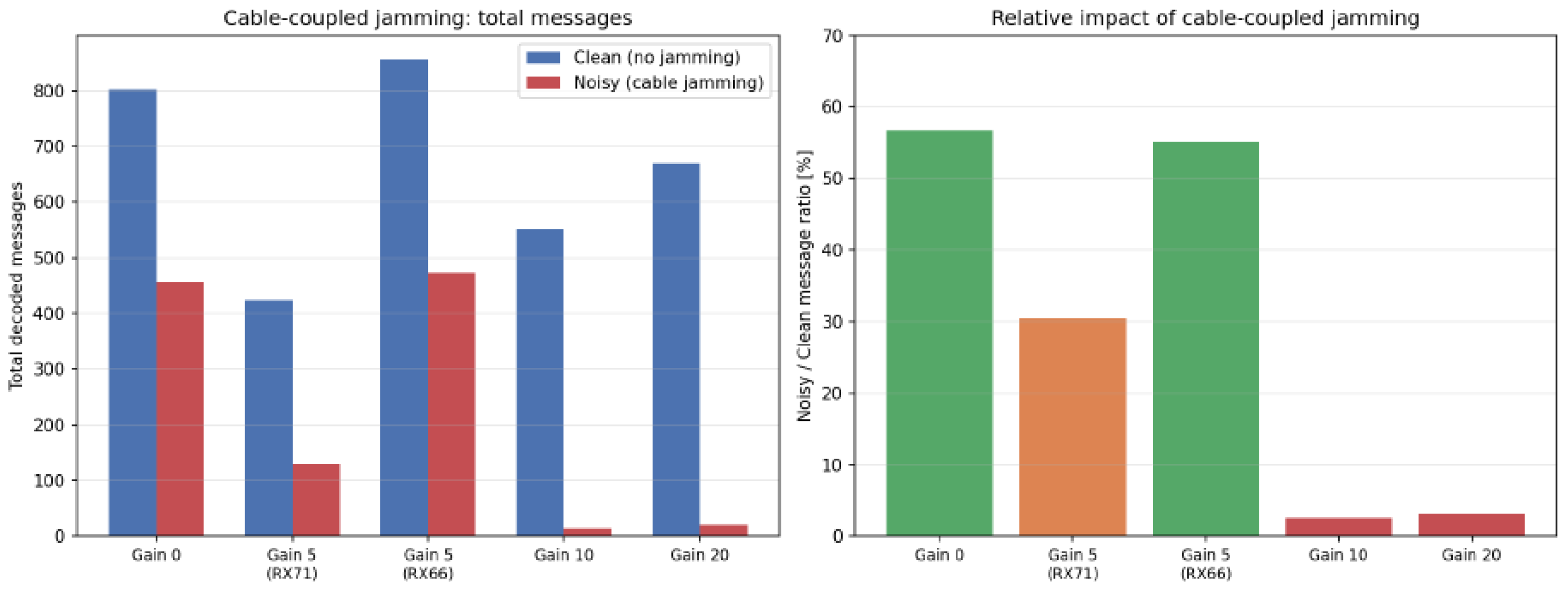
The cable-coupled results in Table 6 confirm, with far greater clarity than the over-the-air campaign, that the noise jammer’s effect is real and gain-dependent, precisely because both branches share the same air traffic at the same instant and any remaining difference is attributable to the jammer alone. For USRP B210, the noisy-to-clean decoded message ratio decreases from 56.66 % under the 0 dB reference condition to 30.42 % at 5 dB and 2.54 % at 10 dB. At 20 dB, only 21 messages are decoded on the noisy branch compared to 670 messages on the clean branch, corresponding to a noisy-to-clean ratio of 3.13 % . Although the values at 10 and 20 dB are not strictly monotonic, both indicate a severe reduction of more than 96 % relative to the simultaneously acquired clean branch. At gain 10 dB and gain 20 dB, the noisy branch retains only 2.54% and 3.13% of the clean branch’s message count respectively, a collapse an order of magnitude more severe than anything observed in the over-the-air campaign at comparable or even higher gain settings. This is consistent with the cable path coupling the jammer’s noise far more efficiently into the receiver than in the case of the over-the-air path used in the earlier campaign, where propagation loss and antenna pattern mismatch attenuate the interference substantially before it reaches the receive antenna. The clean and noisy branch message counts and their ratio across the jammer gain settings are shown in Figure 12. At gain 5 dB, the picture is much clearer as well as very helpful for knowing where the receiver’s own operating point is. The receiver has a gain of 71 dB on the B210. In this case, the noisy portion of the tree holds 30.42% of the clean portion of the tree’s messages. Reducing the B210’s own receive gain to 66 dB at the exact same jammer gain of 5 dB increased the retained portion to 55.19%, nearly matching the baseline (56.66%) of an unaltered gain of 0 dB. As there are no other changes between these two conditions (only the receiver’s own front-end gain changed), it can be reasonably concluded that at a gain of 71 dB, the B210’s A/D converter is being driven close to saturation due to both actual signal and injected noise; and when you take away 5 dB from the receiver’s front-end gain, the receiver will move out of its non-linear area and restore a lot of its ability to decode a message, despite having the same total quantity of injected interference.
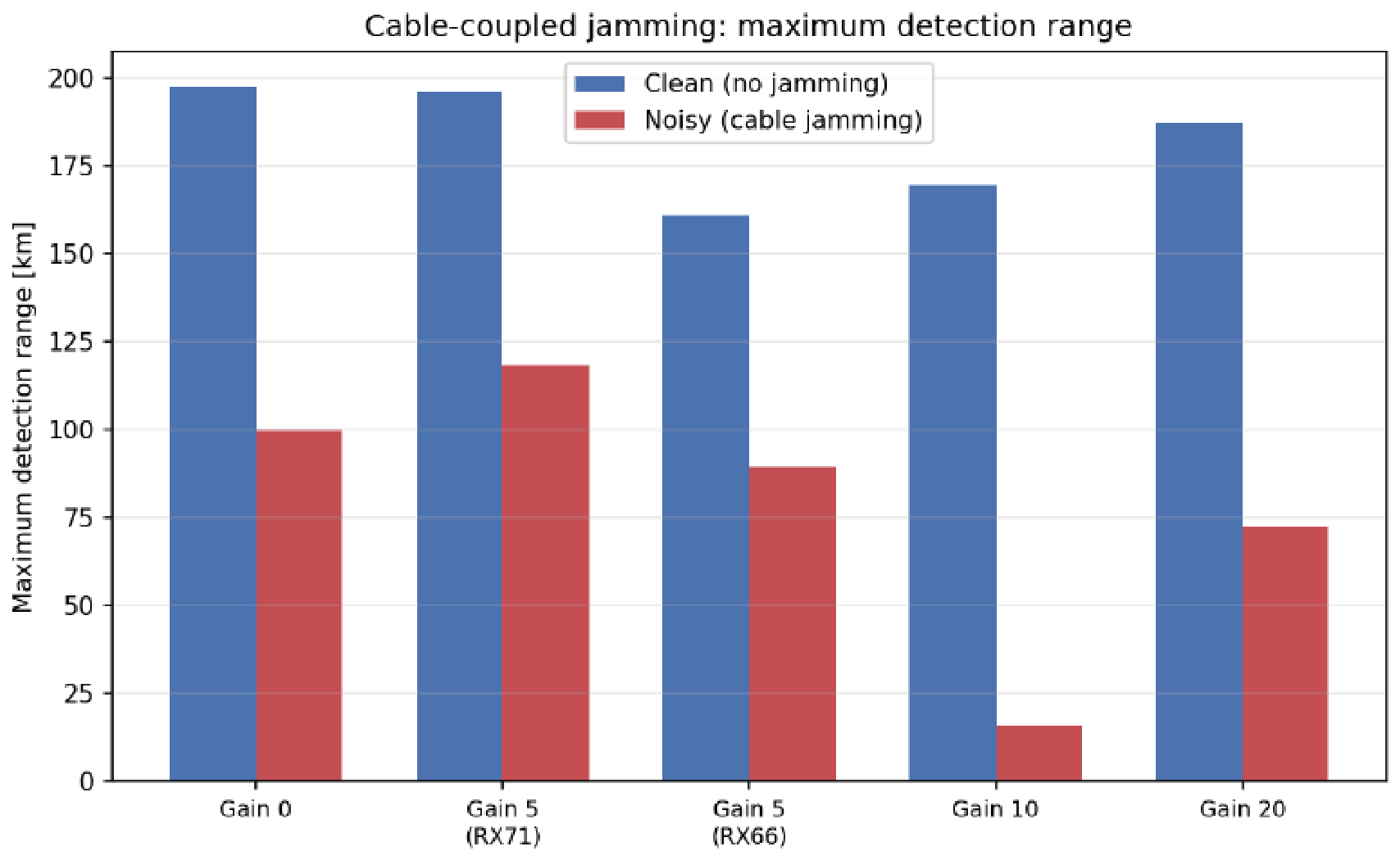
The maximum-range results in Figure 13 reinforce the same picture. At gain 10 dB, the noisy branch’s maximum range collapses to just 16.0 km, computed from a single aircraft, against a clean branch range of 169.7 km measured over the same 5 min window; the small sample size at this condition (a single decoded position) means this figure should be read as indicative of severe degradation rather than a precisely characterized sensitivity floor. When the jamming gain was set to 5 dB and the receiver was backed off to gain 66 dB, the noisy branch’s range (89.7 km) is much closer to its corresponding clean-branch range (161.0 km) than when using a jamming gain of 5 dB with the receiver at gain 71 dB (118.3 km noisy against 196.1 km clean, although the small number of aircraft heard on the noisy branch at this condition, three, limits how precisely this maximum can be interpreted), consistent with the message-count evidence that receiver gain back-off meaningfully improves robustness to a fixed jamming level.
The clean-branch message count (Table 6) fluctuates between 424 and 857 purely due to natural traffic variation between the five sequential 5 min windows, but the noisy-to-clean ratio isolates the jammer’s effect directly from that fluctuation, since both branches experienced identical traffic in each window.
It is also interesting to estimate the number of messages decoded by the noisy receiving branch that include the aircraft position information (latitude and longitude, respectively) as a function of the jammer gain. In the last column of Table 6, the ratio between the number of noisy position-bearing messages and the total number of decoded messages over the noisy branch is provided. The values of this ratio corresponding to the noisy position-bearing messages are 92.75 % , 88.37 % , 28.57 % , and 28.57 % for jammer gains of 0 dB, 5 dB (−107 dBm), 10 dB, and 20 dB, respectively. Comparing the noisy-to-clean ratio and the noisy position-bearing ratio, from the fourth and seventh columns of Table 6, respectively, a similar dependency on the jammer gain is noticed, i.e., the USRP B210 receiver performs considerably well with the increase of the jammer gain from 0 dB to 5 dB and decays and flattens rapidly in a higher jammer level range (above 10 dB).
In the second cable-coupled jamming experiment, a pair of Adalm-Pluto platforms was used, and the same principle of simultaneous clean and noisy reception from a common antenna feed was maintained. The results obtained for the ADALM-Pluto receiver pair are presented in Table 7. The Adalm-Pluto exhibits a different response at the intermediate jammer levels. Its noisy-to-clean decoded message ratio is 74.73 % at the 0 dB reference condition, decreases to 36.91 % at 5 dB, and increases to 44.59 % at 10 dB. At the strongest common condition of 20 dB, however, the noisy branch decodes only 5 messages compared with 884 messages on the clean branch, corresponding to a noisy-to-clean ratio of only 0.57 % . A similar trend is observed for noisy position-bearing messages: the corresponding ratio values are 97.81 % , 93.45 % , 93.06 % , and 0.00 % for jammer gains of 0, 5, 10, and 20 dB, respectively.
In the third and final cable-coupled jamming experiment, two USRP B200mini receivers were used with a similar setup as in the previous two experiments and the receiver performance meters were estimated and included in Table 8. Thus, the USRP B200mini shows substantially stronger performance degradation at the intermediate 10 dB jammer setting. Its noisy-to-clean ratio decreases from 46.00 % at 0 dB to 20.86 % at 5 dB, 3.98 % at 10 dB, and only 0.31 % at 20 dB. The noisy position-bearing message ratio shows the same behavior, corresponding to the same jammer gain values, with values of 89.19 % , down to 87.65 % , 62.96 % , and 0 % , respectively.
For Adalm-Pluto and USRP B200mini receivers, similar histograms were obtained for USRP B210, which are shown in Figure 12 and Figure 13.
Comparing the performance results from Table 6, Table 7 and Table 8, obtained for the three cable-coupled jamming experiments presented above, we can conclude that, under the same conditions, the Adalm-Pluto preserves a considerably larger fraction of both decoded ADS-B messages and position-bearing messages than the USRP B210 and USRP B200mini at the 10 dB jammer setting. This advantage of the Adalm-Pluto receiver over the USRP receivers, at low and moderate jamming gain values, can be explained by the fact that the Adalm-Pluto SDR runs all physical RF front-end commands using the embedded ARM processor, while USRPs transfer many processing commands onto the host computer. At the strongest common jammer setting of 20 dB, all three platforms exhibit severe degradation in decoded-message performance. The USRP B210 retains 3.13 % of the corresponding clean-branch message count, whereas the Adalm-Pluto and USRP B200mini retain only 0.57 % and 0.31 % , respectively. The measurements therefore demonstrate that sufficiently strong cable-coupled broadband interference can reduce successful ADS-B decoding by more than two orders of magnitude relative to simultaneous clean reception.

5.3. External Validation in Comparison with FlightRadar24 Under Over-the-Air Generated Jamming Conditions

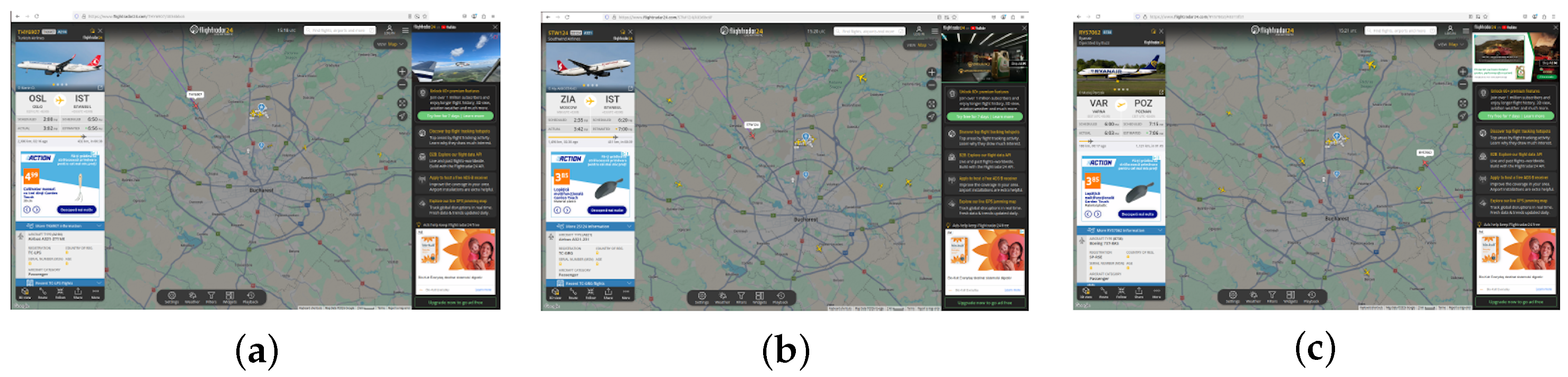
In order to have an external validation of the received ADS-B information used as the basis for the analysis included in Section 5.1 and Section 5.2, data from the FlightRadar24 service was used. However, it has to be mentioned that this comparison is intended as external validation of aircraft identity and general trajectory consistency, rather than a rigorous ground-truth accuracy evaluation of the decoded coordinates. As described in the following paragraphs, three ICAO addresses decoded during the no-jamming session were looked up directly on FlightRadar24 by their callsign, with the exact aircraft selected and visible on the live map at the time of the screenshot, rather than inferred from the general traffic picture. Figure 14 shows capture examples for three different aircraft that were collected during the different measurement campaigns.
Turkish Airlines flight THY6907 (ICAO 4bb213, OSL-IST) was decoded with a valid position by all four SDR platforms during the no-jamming session. Figure 14a shows THY6907 selected directly on FlightRadar24 at 18:18:54 local time, northwest of Bucharest; at this instant, the position decoded from the USRP B200mini’s log (44.5727° N, 25.9415° E) places the aircraft 17.4 km from the receive antenna, in the same direction shown on the map. The aircraft’s track was followed by all four receivers as it continued past the antenna, reaching a minimum distance of under 2 km before moving away again.
Southwind Airlines flight STW124 (ICAO 4b9e47, ZIA-IST) was likewise decoded by all four platforms, including the DXPatrol MK4. Figure 14b shows STW124 selected on FlightRadar24 at 18:20:50 local time; the corresponding decoded positions place the aircraft between 18.5 and 19.8 km from the antenna across the three 12-bit platforms at this time, narrowing as the aircraft approached a minimum of 4.0 km on the Adalm-Pluto, USRP B200mini and USRP B210 logs. The DXPatrol MK4, consistent with its limited sensitivity, only acquired this aircraft once it had closed to within 9.3 km, decoding just five messages between 9.3 km and 4.0 km, a window that illustrates concretely how the 8-bit platform’s effective range is confined to short-range, high-SNR geometry even for an aircraft that the 12-bit platforms tracked over a much wider distance interval.
Ryanair flight RYS7062 (ICAO 48c224, VAR-POZ) provides a direct check on the DXPatrol MK4’s reported maximum range for the no-jamming condition (26.7 km, Table 3). Figure 14c shows RYS7062 selected on FlightRadar24 at 18:21:15 local time, north-east of the antenna; the DXPatrol MK4 decoded this aircraft between 26.0 km and 26.7 km over a short five-message window starting at 18:22:16, essentially at the edge of its detection capability, while the three 12-bit platforms continued tracking the same aircraft out to 40–48 km as it moved further away.
These three cross-checks confirm that the decoded ICAO addresses, callsigns and positions correspond to genuine, externally verifiable air traffic, and that the contrast in effective range between the DXPatrol MK4 and the three 12-bit platforms observed in Table 3 is visible at the level of individual aircraft tracks: the same aircraft (STW124, RYS7062) was tracked by the 12-bit platforms over a substantially wider distance window than the DXPatrol MK4 was able to acquire it.

6. Conclusions and Future Work

This paper analyzed the performance obtained when receiving ADS-B signals, when using as hardware several different software-defined radio platforms and a GNU Radio framework as software environment. Four SDR platforms were used in the implemented testbed, which were connected to the same antenna using an active RF splitter. The receive performance was evaluated in three different scenarios, without any interference, in the presence of a jamming signal transmitted over the air and in the presence of a jamming signal transmitted over a coaxial cable, using an RF combiner. The total number of received ADS-B packets and the number of correctly decoded packets were used as metrics to evaluate the performance of the reception process. As platform-specific optimization could produce different absolute results, we intend in the future to identity for each SDR platform the optimal configuration for ADS-B signal reception.
Future research will expand this comparison to include further SDR platforms, i.e., HackRF One, LimeSDR and RTL-SDR-based receivers, which will allow for the analysis of different RF front-end architectures, ADC resolutions, and host interface constraints. In addition, the test environment will be improved by adding an LNA before the receiving antenna. By evaluating the ADS-B signal detection, we will be able to measure and quantify the impact that the LNA noise figure has on the detection of ADS-B signals. We also intend to expand the cable-coupled jamming experiment to include other SDR platforms.
Another research area is the evaluation of various antenna configurations used for ADS-B 1090 MHz reception. Researchers plan to use both commercially purchased antennas and homemade “DIY” antennas like quarter-wave monopoles, collinear antennas, etc. The goal of this research effort is to understand how antenna gain, radiation patterns, mounting heights, losses within the cable and impedance match affect ADS-B message count, aircraft counted, valid position counts and maximum reception ranges. Furthermore, embedded ADS-B receiver modules previously developed by the authors [17] will also be included in the extended evaluation campaign. Tests will be performed using the same antenna, splitter, and logging conditions as the SDR platforms, allowing a direct comparison between software-defined receivers, commercial ADS-B receivers and custom embedded modules.
To have control of the ADS-B packet source and of the propagation environment, we intend to use an ADS-B signal generator, which will also allow us to obtain receiver operating characteristic (ROC) curves for the different SDR platforms used as receivers.
Future work will also consider higher sampling rates for the ADS-B receiver. The current Framer and Demodulator blocks are designed for 2 MSPS, corresponding to two samples per ADS-B bit. Increasing the sampling rate would require adapting the preamble detection and PPM demodulation stages to process several samples within each half-symbol. This would provide a finer temporal representation of the received ADS-B pulses and may improve preamble and bit detection under more difficult reception conditions.
Finally, to increase the reliability of the statistics reported in the study, future measurements are planned to be conducted over much larger temporal scales (weeks or even months). Longer collection periods will help reduce variability due to factors like traffic volume, weather conditions, flight paths and random radio-frequency interference. This will allow the creation of larger datasets for obtaining statistical validation and will enable researchers to accurately compare ADS-B message decoding rates among different SDR implementations, antenna types and receive configuration combinations using metrics such as mean and maximum message rates per hour/minute, standard deviations, unique ICAO address counts, valid position report ratios and stable reception performance over time.

Author Contributions

Conceptualization, A.M. and V.-S.H.; methodology, A.M.; software, A.-G.G. and C.-P.O.; validation, V.-S.H., A.-G.G. and A.M.; formal analysis, A.M. and V.-S.H.; investigation, V.-S.H., A.M. and C.V.; resources, V.-S.H.; data curation, C.-P.O.; writing—original draft preparation, V.-S.H. and C.-P.O.; writing—review and editing, A.M. and C.V.; visualization, C.-P.O. and V.-S.H.; supervision, A.M.; project administration, A.M. and C.V.; funding acquisition, A.M. All authors have read and agreed to the published version of the manuscript.

Funding

This work was supported by a grant of the Ministry of Research, Innovation and Digitization, CC-CDI—UEFISCDI, project number PN-1V-P7-7.1-PED-2024-0741, within PNCDI IV.

Data Availability Statement

The experiments that were performed to obtain the results that were presented in the paper did not led to the creation of a new dataset. The raw data supporting the conclusions of this article will be made available by the authors on request.

Acknowledgments

Some of the hardware that was used during the measurement campaigns was provided by the Vodafone Innovation Hub at National University of Science and Technology POLITEHNICA Bucharest. The authors would like to sincerely thank the editors, reviewers, and editorial staff for their valuable comments and efforts during the review process of this manuscript.

Conflicts of Interest

The authors declare no conflicts of interest.

Abbreviations

The following abbreviations are used in this manuscript:
1090 ES1090 MHz Extended Squitter
ADCAnalog-to-Digital Converter
ADMMAlternating Direction Method of Multipliers
ADS-BAutomatic Dependent Surveillance–Broadcast
AGCAutomatic Gain Control
ATCAir Traffic Control
AWGNAdditive White Gaussian Noise
CAConstant Acceleration
CFARConstant False Alarm Rate
CNNConvolutional Neural Network
CPRCompact Position Reporting
CPUCentral Processing Unit
CRCCyclic Redundancy Check
CSVComma-Separated Values
CVConstant Velocity
DCDirect Current
DDCDigital Down-Conversion
DFDownlink Format
DMADirect Memory Access
DOADirection of Arrival
DVB-TDigital Video Broadcasting–Terrestrial
ENOBEffective Number of Bits
ESExtended Squitter
ETTIFaculty of Electronics, Telecommunications and Information Technology
FPGAField-Programmable Gate Array
FRUITFalse Replies Unsynchronized in Time
GLONASSGlobal Navigation Satellite System of the Russian Federation
GNSSGlobal Navigation Satellite System
GPSGlobal Positioning System
GRCGNU Radio Companion
GSMGlobal System for Mobile Communications
HDLHardware Description Language
ICAOInternational Civil Aviation Organization
IFIntermediate Frequency
IIOIndustrial Input/Output
IMMInteracting Multiple Model
IQIn-Phase and Quadrature
JSONJavaScript Object Notation
KFKalman Filter
LNALow-Noise Amplifier
LTELong-Term Evolution
LSTMLong Short-Term Memory
MDDModel-Based Design
MEOMedium Earth Orbit
MIMOMultiple-Input Multiple-Output
MUSICMultiple Signal Classification
NACpNavigation Accuracy Category for Position
NavICNavigation with Indian Constellation
NICNavigation Integrity Category
PLLPhase-Locked Loop
PPMPulse-Position Modulation
QZSSQuasi-Zenith Satellite System
RFRadio Frequency
RFIRadio-Frequency Interference
RFICRadio-Frequency Integrated Circuit
RNDISRemote Network Driver Interface Specification
ROCReceiver Operating Characteristic
RTL-SDRRTL2832U-Based Software-Defined Radio
RXReceiver
SAWSurface Acoustic Wave
SDRSoftware-Defined Radio
SMASubMiniature Version A
SNRSignal-to-Noise Ratio
SoCSystem-on-Chip
SVDSingular Value Decomposition
TCType Code
TCP/IPTransmission Control Protocol/Internet Protocol
TCXOTemperature-Compensated Crystal Oscillator
TDOATime Difference of Arrival
TXTransmitter
UASUnmanned Aircraft System
UAVUnmanned Aerial Vehicle
UCAUniform Circular Array
UHDUSRP Hardware Driver
ULAUniform Linear Array
UMOPUnique Message-Origin Property
USBUniversal Serial Bus
USRPUniversal Software Radio Peripheral
VCTCXOVoltage-Controlled Temperature-Compensated Crystal Oscillator
VCXOVoltage-Controlled Crystal Oscillator
VGAVariable-Gain Amplifier
ZMQZeroMQ

References

  1. NASA Earthdata. Global Navigation Satellite System. NASA Earthdata. Available online: https://www.earthdata.nasa.gov/data/space-geodesy-techniques/gnss (accessed on 9 July 2026).
  2. GPS.gov. Space Segment. Global Positioning System. Available online: https://www.gps.gov/space-segment (accessed on 9 July 2026).
  3. Information and Analysis Center for Positioning, Navigation and Timing. About GLONASS. GLONASS-IAC. Available online: https://glonass-iac.ru/en/about_glonass/ (accessed on 9 July 2026).
  4. European Space Agency. Galileo: A Constellation of Navigation Satellites. ESA. Available online: https://www.esa.int/Applications/Satellite_navigation/Galileo/Galileo_a_constellation_of_navigation_satellites (accessed on 9 July 2026).
  5. China Satellite Navigation Office. BeiDou Navigation Satellite System Signal in Space Interface Control Document: Open Service Signal B1C, Version 1.0. BeiDou Navigation Satellite System. 2020. Available online: http://en.beidou.gov.cn/SYSTEMS/ICD/202008/P020200803535920317313.pdf (accessed on 9 July 2026).
  6. Cabinet Office, Government of Japan. Overview of the Quasi-Zenith Satellite System. QZSS: Quasi-Zenith Satellite System. Available online: https://qzss.go.jp/en/overview/services/sv01_what.html (accessed on 9 July 2026).
  7. Indian Space Research Organisation. Satellite Navigation Services. ISRO. Available online: https://www.isro.gov.in/SatelliteNavigationServices.html (accessed on 9 July 2026).
  8. Piracci, V.; Cenedese, L.; Biagi, L. ADS-B signals reception: A Software Defined Radio approach. In Proceedings of the 2014 IEEE Metrology for Aerospace (MetroAeroSpace), Benevento, Italy, 29–30 May 2014; pp. 132–137. [Google Scholar] [CrossRef] [Scilit]
  9. Su, X.; Zeng, J.; Li, J.; Hu, S. SDR Reception and Analysis of Civil Aviation ADS-B Signals. In Proceedings of the 2018 IEEE International Conference of Safety Produce Informatization (IICSPI), Chongqing, China, 10–12 December 2018; pp. 893–896. [Google Scholar] [CrossRef] [Scilit]
  10. Mangali, N.K.; Bagmare, V.S. Development of a Power over Ethernet (PoE) Enabled ADS-B Receiver System. In Proceedings of the 2017 International Conference on Wireless Communications, Signal Processing and Networking (WiSPNET), Chennai, India, 22–24 March 2017; pp. 1888–1892. [Google Scholar] [CrossRef] [Scilit]
  11. Ajhari, A.A.; Ibrahim, R.; Pramodana, A.; Pramudito, J.S.; Tasyam, J.R.; Hilmy, W. ADS-B Mobile Ground Station Receiver Flight Surveillance Architecture. In Proceedings of the 2021 International Conference on Artificial Intelligence and Computer Science Technology (ICAICST), Yogyakarta, Indonesia, 29–30 June 2021; pp. 174–178. [Google Scholar]
  12. Wang, X. Receiving and Processing ADS-B Signals for Aircraft Tracking. Bachelor’s Thesis, Universitat Politècnica de Catalunya, Barcelona, Spain, 2019. [Google Scholar]
  13. Spears, J. Building an ADS-B Receiver and Sharing Data with FlightAware, ADS-B Exchange, and Flightradar24. 2024. Available online: https://www.qsl.net/qcwa126/ASDB%20Presentation.pdf (accessed on 9 July 2026).
  14. Köllner, G. Project ADS-B Receiver and Decoder. 2017. Available online: https://www.qsl.net/dl4mea/fpgaadsb/Koellner_Projekt-ADSB3.pdf (accessed on 9 July 2026).
  15. Zhang, Y.; Wang, K.; Long, H. SDR-Based ADS-B with Dual-Frequency for UAS: A Universal Design. In Proceedings of the 2015 IEEE International Conference on Computer and Information Technology; Ubiquitous Computing and Communications; Dependable, Autonomic and Secure Computing; Pervasive Intelligence and Computing, Liverpool, UK, 26–28 October 2015; pp. 59–64. [Google Scholar] [CrossRef] [Scilit]
  16. Peng, W.; Li, Y.; Li, H.; Wen, B. A Novel High-sensitivity ADS-B Receiver Based on RF Direct Logarithmic Detecting. In Proceedings of the 2nd International Conference on Computer Application and System Modeling (2012), Shenyang, China, 27–29 July 2012; pp. 735–737. [Google Scholar]
  17. Hociung, V.-Ș.; Codreanu, N.; Marțian, A. Innovative Solutions for the Development of High-Performance ADS-B Receivers. In Proceedings of the International Spring Seminar on Electronics Technology (ISSE), Budapest, Hungary, 14–18 May 2025; pp. 1–6. [Google Scholar] [CrossRef] [Scilit]
  18. Olivia, G.P.; Olivia, L.; Edwar, E. A Design of ADS-B Receiver Antenna Using Truncated Circular Microstrip Patch in Cubesat Form Factor. In Proceedings of the 2022 IEEE International Conference on Aerospace Electronics and Remote Sensing Technology (ICARES), Yogyakarta, Indonesia, 24–25 November 2022. [Google Scholar] [CrossRef] [Scilit]
  19. Eichstaedt, F.; Budroweit, J. Evaluation of a GNURadio-based Multi-Channel ADS-B Receiver Implemented on a Highly Integrated SDR Platform for Space Application. In Proceedings of the 2022 IEEE Space Hardware and Radio Conference (SHaRC), Las Vegas, NV, USA, 16–19 January 2022. [Google Scholar] [CrossRef] [Scilit]
  20. Raza, S.A. Performance Evaluation of an Open Source SDR-Based ADS-B Receiver. Master’s Thesis, Tallinn University of Technology, Tallinn, Estonia, 2019. [Google Scholar]
  21. Nahiri, L.; Idmouida, H.; Oumimoun, B.; Addaim, A.; Guennoun, Z.; Minaoui, K. An Analysis of SDR-Based ADS-B Receiver Performance for a Future Nanosatellite Payload. In Proceedings of the 2023 IEEE International Conference on Aerospace Electronics and Remote Sensing Technology (ICARES), Bali, Indonesia, 26–27 October 2023. [Google Scholar] [CrossRef] [Scilit]
  22. Li, K.; Kang, J.; Ren, H.; Wu, Q. A Reliable Separation Algorithm of ADS-B Signal Based on Time Domain. IEEE Access 2021, 9, 88019–88026. [Google Scholar] [CrossRef] [Scilit]
  23. Ren, P.; Wang, J.; Song, H.; Zhang, P.; Ban, T. A Novel Multi-Criteria Preamble Detection Algorithm for ADS-B Signals. IEEE Access 2019, 7, 97319–97331. [Google Scholar] [CrossRef] [Scilit]
  24. Chiocchio, S.; Persia, A.; Santucci, F.; Graziosi, F.; Pratesi, M.; Faccio, M. Modeling and evaluation of enhanced reception techniques for ADS-B signals in high interference environments. Phys. Commun. 2020, 42, 101171. [Google Scholar] [CrossRef] [Scilit]
  25. Zou, H.; Ban, T.; Zhuang, Z. An S Mode ADS-B Preamble Detection Algorithm. In Proceedings of the 2019 IEEE 5th International Conference on Computer and Communications (ICCC), Chengdu, China, 6–9 December 2019; pp. 178–182. [Google Scholar] [CrossRef] [Scilit]
  26. Kuang, Z.; Huang, J.; Tan, Y.; Liu, Z.; Liu, Y.; Hu, W. Research on Technology for Separating ADS-B Overlapped Signals. In Proceedings of the 2022 4th International Academic Exchange Conference on Science and Technology Innovation (IAECST), Guangzhou, China, 9–11 December 2022. [Google Scholar] [CrossRef] [Scilit]
  27. Wang, W.; Zhao, H. ADS-B Overlapping Signals Separation Based on Minimum Dispersion Criterion. Digit. Signal Process. 2023, 141, 104172. [Google Scholar] [CrossRef] [Scilit]
  28. Shen, Z.; Zhou, S.; Yu, H. A Novel Anti-jamming ADS-B Receiver Design Based on Wavelet Denoising Algorithm. In Proceedings of the 2016 6th International Workshop on Computer Science and Engineering (WCSE 2016), Tokyo, Japan, 17–19 June 2016; pp. 366–370. [Google Scholar] [CrossRef] [Scilit]
  29. Liu, Z.; Lo, S.; Walter, T. Characterization of ADS-B Performance under GNSS Interference. In Proceedings of the 33rd International Technical Meeting of the Satellite Division of the Institute of Navigation (ION GNSS+ 2020), Virtual, 22–25 September 2022; pp. 3581–3591. [Google Scholar] [CrossRef] [Scilit]
  30. Semke, W.; Allen, N.; Tabassum, A.; McCrink, M.; Moallemi, M.; Snyder, K.; Arnold, E.; Stott, D.; Wing, M.G. Analysis of Radar and ADS-B Influences on Aircraft Detect and Avoid (DAA) Systems. Aerospace 2017, 4, 49. [Google Scholar] [CrossRef] [Scilit]
  31. Shen, H.; Liu, K.; Yao, Y.; Wang, J. An ADS-B Anti-counterfeiting System Based on TDOA. In Proceedings of the 2019 IEEE International Conference on Signal, Information and Data Processing (ICSIDP), Chongqing, China, 11–13 December 2019; pp. 178–183. [Google Scholar] [CrossRef] [Scilit]
  32. Jiang, N.; Qi, S.; Luo, F.; Jun, W.; Wang, W. ADS-B Message Authentication Using Features of Signal in Transition Regions. In Proceedings of the 2019 IEEE International Conference on Signal, Information and Data Processing (ICSIDP), Chongqing, China, 11–13 December 2019; pp. 1–5. [Google Scholar] [CrossRef] [Scilit]
  33. Zha, H.; Tian, Q.; Lin, Y. Real-World ADS-B Signal Recognition Based on Radio Frequency Fingerprinting. In Proceedings of the 2020 IEEE 28th International Conference on Network Protocols (ICNP), Madrid, Spain, 13–16 October 2020; pp. 1–5. [Google Scholar] [CrossRef] [Scilit]
  34. de Boer, T. Automatic Dependent Surveillance-Broadcast (ADS-B); OS3: Osaka, Japan, 2020. [Google Scholar]
  35. Wu, Z.; Shang, T.; Guo, A. Security Issues in Automatic Dependent Surveillance—Broadcast (ADS-B): A Survey. IEEE Access 2020, 8, 122146–122176. [Google Scholar] [CrossRef] [Scilit]
  36. Zhang, K.; Qiao, Y.; Zhang, C. Trajectory Tracking Using Auto-adaptive Multi-model Filtering Method in ADS-B System. In Proceedings of the 2013 Second International Conference on Robot, Vision and Signal Processing, Kitakyushu, Japan, 10–12 December 2013; pp. 93–97. [Google Scholar] [CrossRef] [Scilit]
  37. Bolton, S.; Dill, R.; Grimaila, M.R.; Hodson, D. ADS-B classification using multivariate long short-term memory–fully convolutional networks and data reduction techniques. J. Supercomput. 2023, 79, 2281–2307. [Google Scholar] [CrossRef] [Scilit]
  38. Lin, H.; Yang, H.C. A method of simulation of ADS-B information source 2013. In Proceedings of the International Workshop on Microwave and Millimeter Wave Circuits and System Technology, Chengdu, China, 24–25 October 2013; pp. 483–485. [Google Scholar] [CrossRef] [Scilit]
  39. Sun, J. ADS-B Decoding Guide; Release 0.3; Delft University of Technology: Delft, The Netherlands, 2017. [Google Scholar]
  40. Laporte-Fauret, B.; Tajan, R.; Ferré, G. ADS-B Transmitter/Receiver Simulation to Decode Real Aircraft Trajectories with Software Defined Radios. In Proceedings of the 2019 29th Annual Conference of the European Association for Education in Electrical and Information Engineering (EAEEIE), Ruse, Bulgaria, 4–6 September 2020; pp. 1–6. [Google Scholar] [CrossRef] [Scilit]
  41. Molla, D.M.; Badis, H.; George, L.; Berbineau, M. Software Defined Radio Platforms for Wireless Technologies. IEEE Access 2022, 10, 26203–26229. [Google Scholar] [CrossRef] [Scilit]
  42. Budroweit, J.; Eichstaedt, F.; Delovski, T. Aircraft Surveillance from Space: The Future of Air Traffic Control? Space-Based ADS-B, Status, Challenges and Opportunities. IEEE Microw. Mag. 2024, 25, 68–76. [Google Scholar] [CrossRef] [Scilit]
  43. Ceballos-Gutierrez, J.; Aranda-Escolastico, E.; Moreno-Salinas, D. Enhancing Spectrum Utilization in Mode S Surveillance Systems via 1090ES ADS-B. IEEE Open J. Commun. Soc. 2026, 7, 138–152. [Google Scholar] [CrossRef] [Scilit]
  44. ED-102B; Integrated Change 1 and Change 2|MOPS for 1090 MHz Extended Squitter ADS-B and TIS-B Integrated Change 1 and Change 2. EUROCAE: St.-Denis, France, 2026.
  45. Akeela, R.; Dezfouli, B. Software-defined Radios: Architecture, State-of-the-art, and Challenges. arXiv 2018, arXiv:1804.06564. [Google Scholar] [CrossRef] [Scilit]
  46. Ettus Research. USRP B200mini: 1 × 1, 70 MHz–6 GHz SDR/Cognitive Radio. Ettus Research, a National Instruments Brand. Available online: https://www.ettus.com/all-products/usrp-b200mini/ (accessed on 11 July 2026).
  47. Analog Devices. AD9364 RF Agile Transceiver Data Sheet; Rev. A; Analog Devices: Norwood, MA, USA, 2014; Available online: https://www.analog.com/media/en/technical-documentation/data-sheets/ad9364.pdf (accessed on 11 July 2026).
  48. Ettus Research. USRP B210 SDR Kit: Dual Channel Transceiver, 70 MHz–6 GHz. Ettus Research, a National Instruments Brand. Available online: https://www.ettus.com/all-products/ub210-kit/ (accessed on 11 July 2026).
  49. Analog Devices. AD9361 RF Agile Transceiver Data Sheet; Rev. E; Analog Devices: Norwood, MA, USA, 2019; Available online: https://www.analog.com/media/en/technical-documentation/data-sheets/AD9361.pdf (accessed on 11 July 2026).
  50. DXPatrol. Ultra Wide-Band Coverage SDR Receiver MK4. Available online: https://static.dxengineering.com/global/images/instructions/dxp-dx-patrolmk4_sn.pdf (accessed on 11 July 2026).
  51. DXPatrol. DXPatrol Official Website. Available online: https://www.dxpatrol.pt (accessed on 11 July 2026).
  52. Proakis, J.G.; Manolakis, D.G. Digital Signal Processing: Principles, Algorithms and Applications, 4th ed.; Pearson Prentice Hall: Upper Saddle River, NJ, USA, 2007. [Google Scholar]
  53. Analog Devices. ADALM–PLUTO Detailed Specifications. Analog Devices Wiki. 27 January 2021. Available online: https://wiki.analog.com/university/tools/pluto/specs (accessed on 9 July 2026).
  54. Analog Devices. Basic Internals of Pluto. Analog Devices Wiki. 10 August 2017. Available online: https://wiki.analog.com/university/tools/pluto/users/understanding (accessed on 11 July 2026).
  55. Analog Devices. AD9363 RF Agile Transceiver Data Sheet; Rev. B; Analog Devices: Norwood, MA, USA, 2017; Available online: https://www.analog.com/media/en/technical-documentation/data-sheets/AD9363.pdf (accessed on 11 July 2026).
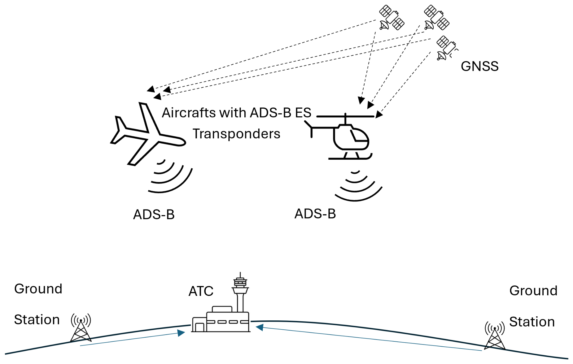
Figure 1. ADS-B overview.
Futureinternet 18 00491 g001
Figure 2. Frame format of ADS-B signals.
Futureinternet 18 00491 g002
Figure 3. Block diagram for the measurement setup including four different SDR platforms.
Futureinternet 18 00491 g003
Figure 4. Picture of the measurement setup including four different SDR platforms.
Futureinternet 18 00491 g004
Figure 5. Block diagram of the measurement setup for the scenario including a jamming signal injected directly into the RF signal path.
Futureinternet 18 00491 g005
Figure 6. Cable-coupled jamming setup for USRP B210 receiver: two USRP B210 units (left), one connected directly to the main splitter (bottom) and one connected through a secondary splitter combining the antenna feed with the jammer noise injected over a cable path (top); the jammer’s own USRP B200mini and dedicated laptop are visible on the right.
Futureinternet 18 00491 g006
Figure 7. GNU Radio flowgraph and signal processing code for the receive branches when the reception was performed using USRP SDR platforms.
Futureinternet 18 00491 g007
Figure 8. Logic software diagram of ADS-B signal processing.
Futureinternet 18 00491 g008
Figure 9. Comparative performance under jamming for the four SDR platforms: (left) total decoded messages; (centre) unique ICAO addresses tracked; (right) position decode rate, grouped by platform and jamming condition.
Futureinternet 18 00491 g009
Figure 10. Decoded message rate as a function of in-band broadband noise jamming gain, for each of the four SDR platforms.
Futureinternet 18 00491 g010
Figure 11. Maximum ADS-B detection range per platform and jamming condition, computed from decoded aircraft positions.
Futureinternet 18 00491 g011
Figure 12. Cable-coupled jamming campaign (USRP B210 receiver): (left) total decoded messages for the clean and noisy branches; (right) noisy-to-clean message ratio across jammer gain settings (green—ratios above 50%, orange—ratios between 10% and 50%, red—ratios below 10%).
Futureinternet 18 00491 g012
Figure 13. Cable-coupled jamming campaign (USRP B210 receiver): maximum detection range for the clean and noisy branches.
Futureinternet 18 00491 g013
Figure 14. External validation in comparison with FlightRadar24: (a) Turkish Airlines flight THY6907 (OSL-IST), decoded with a valid position by all four SDR platforms during the no-jamming session; (b) Southwind Airlines flight STW124 (ZIA-IST), decoded by all four platforms, including the DXPatrol MK4, which only acquired it at short range; (c) Ryanair flight RYS7062 (VAR-POZ), decoded by the DXPatrol MK4 at a distance closely matching its reported maximum range for the no-jamming condition.
Futureinternet 18 00491 g014
Table 1. Prior studies summary.
Author/ReferencePlatform(s)Key FindingLimitation
Piracci [8]Custom SDR + LabVIEWControlled interference testingSingle platform only
Shen [28]USRP + wavelet denoisingAnti-jamming performanceSimulation-focused
Mangali [10]RTL-SDR + Raspberry PiPoE-enabled low-cost deploymentNo comparative benchmark
Raza [20]BladeRFHigh-gain antenna extensionSingle device evaluation
Molla [41]Multiple SDRsGeneral wireless platform comparisonNot ADS-B specific
Su [9]KZ-SDRSelf developed SDRSingle platform only, No interference analysis
Table 2. Comparison of the key specifications for the SDR platforms used in the experimental setup.
SDR PlatformRF Transceiver/
Tuner
Frequency RangeInstantaneous BandwidthADC ResolutionSample Rate
USRP B200miniAD936470 MHz–6 GHzUp to 56 MHz12-bitUp to 61.44 MS/s
USRP B210AD936170 MHz–6 GHzUp to 56 MHz12-bitUp to 61.44 MS/s
DX-Patrol MK4R820T2 + RTL2832U100 kHz–2 GHzUp to 3.2 MHz8-bitUp to 3.2 MS/s
Adalm-PlutoAD936370 MHz–6 GHz aUp to 20 MHz12-bitUp to 61.44 MS/s
a The extended 70 MHz–6 GHz range corresponds to the firmware-unlocked configuration. The official Adalm-Pluto frequency range is 325 MHz–3.8 GHz.
Table 3. Summary of the joint comparative measurement for the evaluated SDR platforms for the over-the-air jamming scenario.
SDR PlatformJamming ConditionTotal MsgsUnique a/cw/Pos.Pos. Rate [%]Rate [/min]
DXPatrol MK4No jamming1571066.671.49
Gain 20 dB (−92 dBm)115436.361.10
Gain 40 dB (−72 dBm)2451770.832.39
Gain 60 dB (−52 dBm)2200.000.20
Adalm-PlutoNo jamming8821681992.8687.87
Gain 20 dB (−92 dBm)7522270894.1574.95
Gain 40 dB (−72 dBm)9511690294.8594.67
Gain 60 dB (−52 dBm)146214.291.40
USRP B200miniNo jamming5361749592.3553.35
Gain 20 dB (−92 dBm)2691921379.1826.81
Gain 40 dB (−72 dBm)4781743691.2147.62
Gain 60 dB (−52 dBm)124433.331.20
USRP B210No jamming8211776192.6981.76
Gain 20 dB (−92 dBm)7471771095.0574.42
Gain 40 dB (−72 dBm)8611682195.3585.79
Gain 60 dB (−52 dBm)10979688.0710.86
Each SDR platform was connected to the same antenna through an active RF splitter. The measurements were performed under one reference condition without jamming and three broadband Gaussian noise jamming conditions at 1.09 GHz.
Table 4. Cost vs. performance comparison for SDR platforms used in the experimental setup.
SDR PlatformAverage Price (EUR)Market SegmentTypical ApplicationsMessages/min (No Jamming)Cost/Msg (No Jamming)Messages/min (Strong Jamming)Cost/Msg (Strong Jamming)
USRP B200mini1500ProfessionalResearch53.3528.111.201250
USRP B2102500ProfessionalResearch81.7630.5710.86230.2
DX-Patrol MK4100BudgetEducational/
hobby
1.4967.110.20500
Adalm-Pluto250Mid-rangeEducational/
research bridge platform
87.872.841.40178.5
Table 5. Maximum and average great-circle distance from the receiver antenna to aircraft decoded with a valid position, per SDR platform and jamming condition, after CPR artifact filtering.
SDR PlatformJamming ConditionMax. Range [km]Avg. Range [km]A/c w/Position
DXPatrol MK4No jamming26.718.02
Gain 20 dB (−92 dBm)26.125.72
Gain 40 dB (−72 dBm)28.412.43
Gain 60 dB (−52 dBm)0
Adalm-PlutoNo jamming61.533.115
Gain 20 dB (−92 dBm)95.040.616
Gain 40 dB (−72 dBm)59.828.212
Gain 60 dB (−52 dBm)7.27.21
USRP B200miniNo jamming66.333.016
Gain 20 dB (−92 dBm)75.441.19
Gain 40 dB (−72 dBm)65.227.612
Gain 60 dB (−52 dBm)29.921.82
USRP B210No jamming66.830.616
Gain 20 dB (−92 dBm)63.234.713
Gain 40 dB (−72 dBm)64.326.013
Gain 60 dB (−52 dBm)38.926.76
Table 6. Cable-coupled jamming results for the USRP B210 receiver. The clean and noisy receive branches used simultaneously the same antenna feed.
Jammer GainDecoded MessagesUnique AircraftPosition Messages
CleanNoisyNoisy/Clean Ratio [%]CleanNoisyNoisy Pos. Ratio [%]
0 dB80345556.66201792.75
5 dB (−107 dBm)
(RX gain 71 dB)
42412930.4216888.37
5 dB (−107 dBm)
(RX gain 66 dB)
85747355.19191692.18
10 dB (−102 dBm)552142.5413428.57
20 dB (−92 dBm)670213.13191028.57
Each condition was evaluated for approximately 5 min.
Table 7. Cable-coupled jamming results for the Adalm-Pluto receiver. The clean and noisy receive branches used simultaneously the same antenna feed.
Jammer GainDecoded MessagesUnique AircraftPosition Messages
CleanNoisyNoisy/Clean Ratio [%]CleanNoisyNoisy Pos. Ratio [%]
0 dB103777574.7315797.81
5 dB74527536.9115793.45
10 dB71131744.5920893.06
20 dB88450.571920.00
Each condition was evaluated for approximately 5 min.
Table 8. Cable-coupled jamming results for the USRP B200mini receiver. The clean and noisy receive branches used simultaneously the same antenna feed.
Jammer GainDecoded MessagesUnique AircraftPosition Messages
CleanNoisyNoisy/Clean Ratio [%]CleanNoisyNoisy Pos. Ratio [%]
0 dB56325946.00101489.19
5 dB81517020.86111387.65
10 dB678273.988662.96
20 dB64020.311210.00
Each condition was evaluated for approximately 5 min.
Disclaimer/Publisher’s Note: The statements, opinions and data contained in all publications are solely those of the individual author(s) and contributor(s) and not of MDPI and/or the editor(s). MDPI and/or the editor(s) disclaim responsibility for any injury to people or property resulting from any ideas, methods, instructions or products referred to in the content.