
Lower-Latency Screen Updates over QUIC with Forward Error Correction


Abstract
1. Introduction
2. Background and Related Work
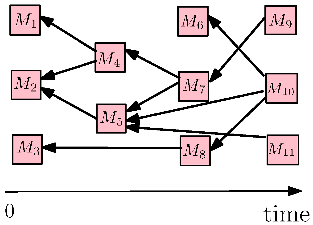
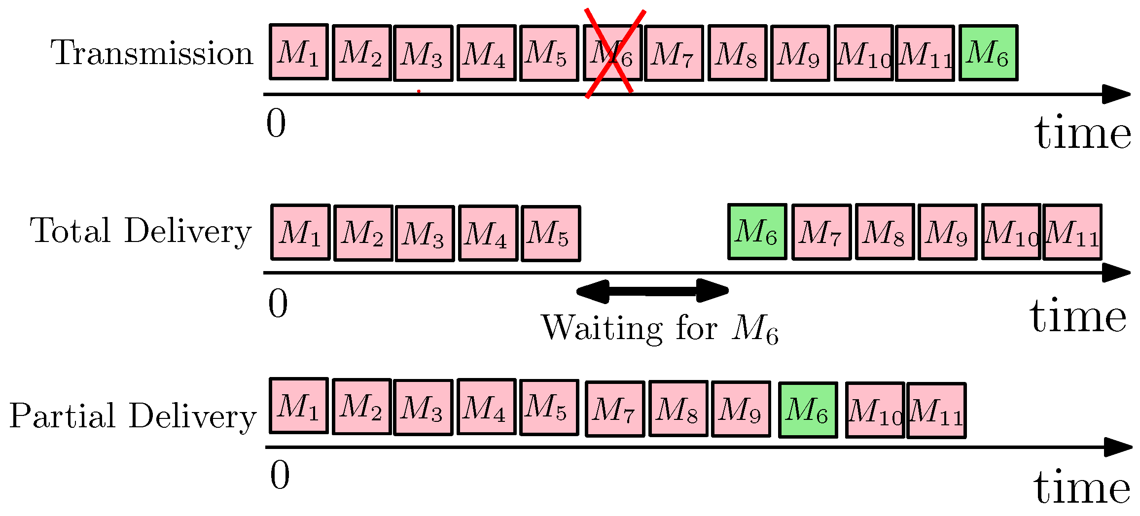
2.1. Consistency Fences for Partial Ordering
2.2. QUIC and FEC
- Integrating TLS as a part of the protocol for security.
- Multi-streaming of web resources to avoid the HOL blocking problem.
- A 0-RTT connection setup for the clients, which previously connected to a server as apposed to TCP’s classic three-way handshake for any new connection.
- User-space level implementations, which provide easier development and deployment compared to kernel code.
3. Use Case: Pixel-Based Screen Sharing Protocols
- Streaming updates: The client sends one request to receive a stream of screen updates from the server (Section 6.1).
- Non-streaming updates: The client sends a request for the first update, then finishes downloading it, and after a while (e.g., 0.4 s) sends the request for the second update, and so on (Section 6.2).
4. Design and Implementation
4.1. Partial Ordering for Screen Updates over QUIC
4.2. Adding FEC to ngtcp2 [8]
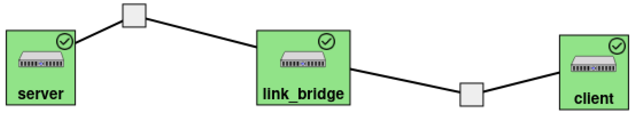
5. Evaluation Setup on Emulab
6. Empirical Results on Emulab
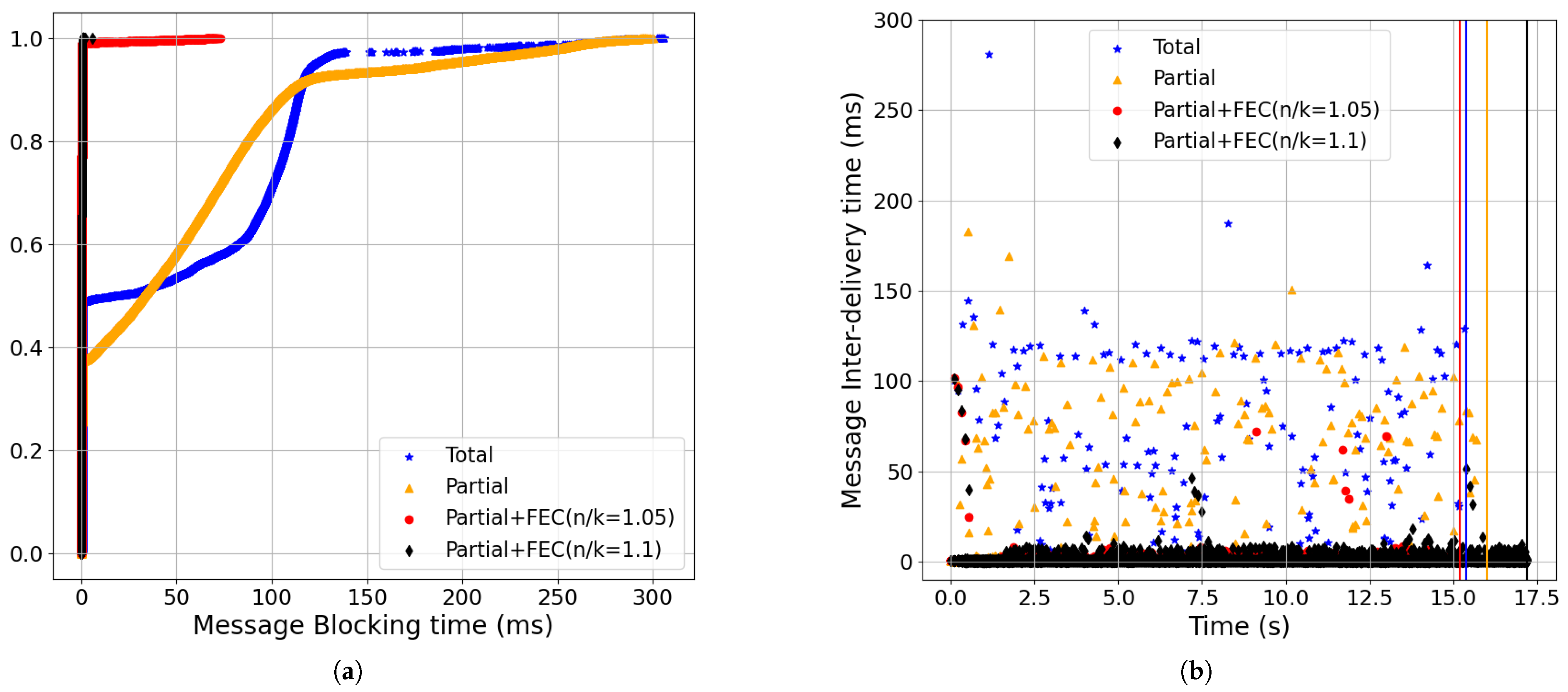
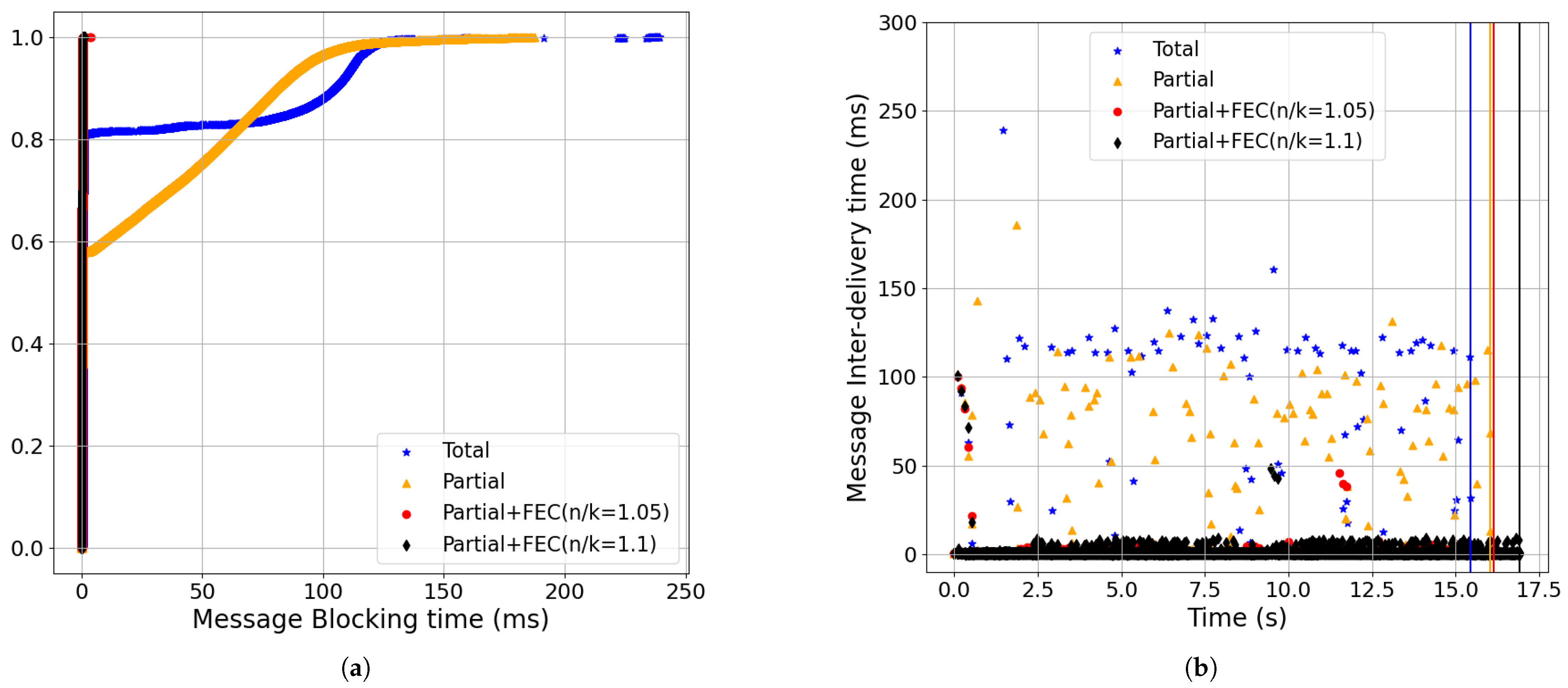
- Partial+FEC reduced message-blocking and message inter-delivery time for the streaming updates workload compared to total and partial delivery (Section 6.1). For example, the 99-percentile of message-blocking time for partial+FEC (n/k = 1.05) was 0.4 ms, while the 80-percentile of total was already 101 ms, and the 99-percentile was 230 ms (baseline setting: 0.5% loss, 100 ms RTT, 100 Mbps, BBR). See Figure 9.
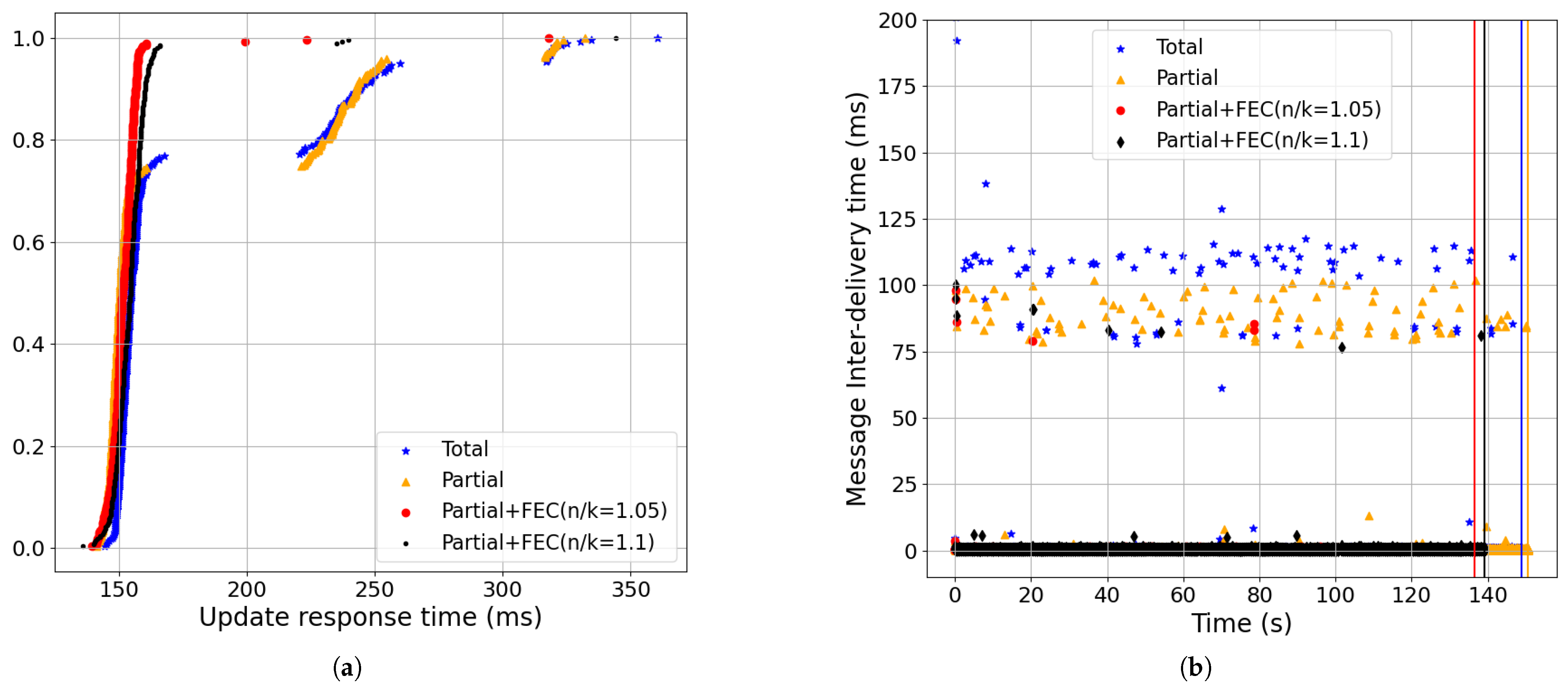
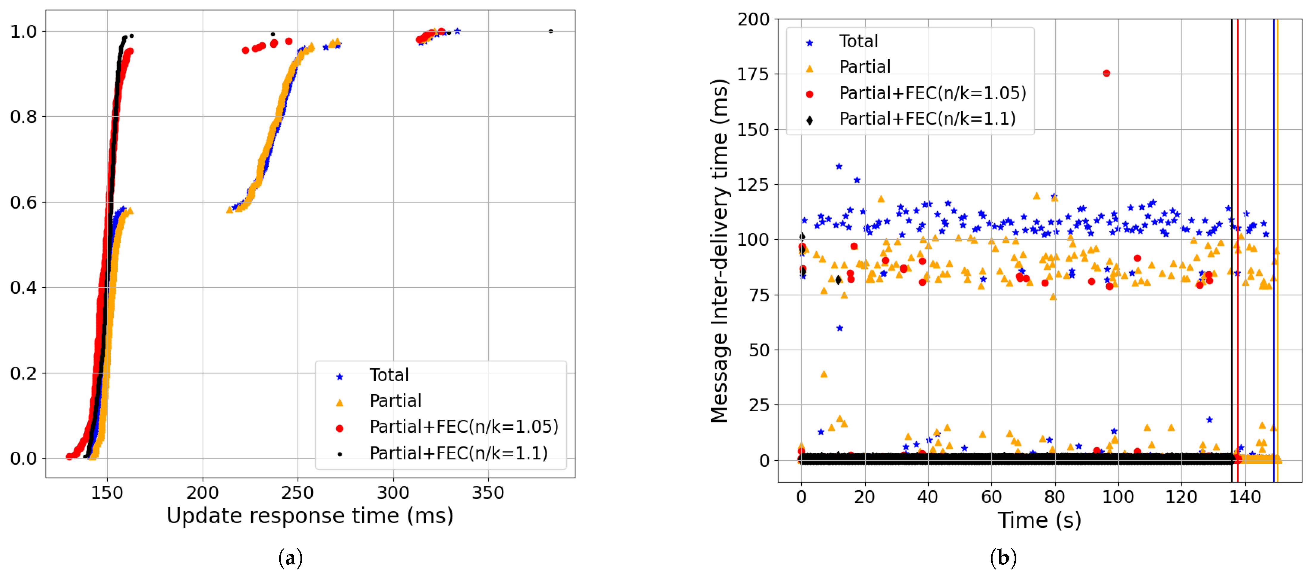
- Partial+FEC reduced the update response time, message inter-delivery time, and the completion time for the non-streaming updates workload compared to total and partial delivery (Section 6.2). For example, the 99-percentile of update response time for partial+FEC (n/k = 1.05) was 162 ms, while the 99-percentile of total was 325 ms. Also, the completion time of partial+FEC (n/k = 1.05) was 137 v.s. 149 s for total (baseline setting: 0.5% loss, 100 ms RTT, 100 Mbps, BBR). See Figure 18.
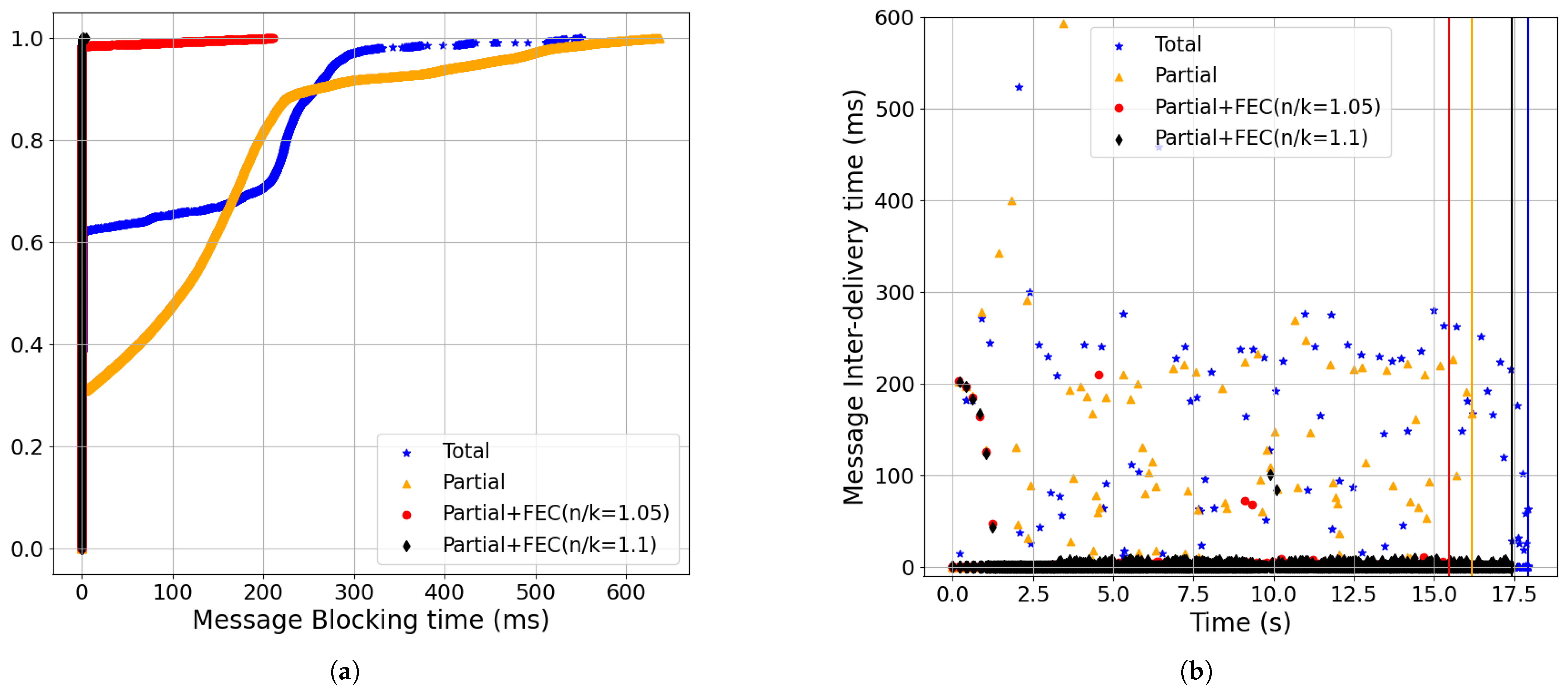
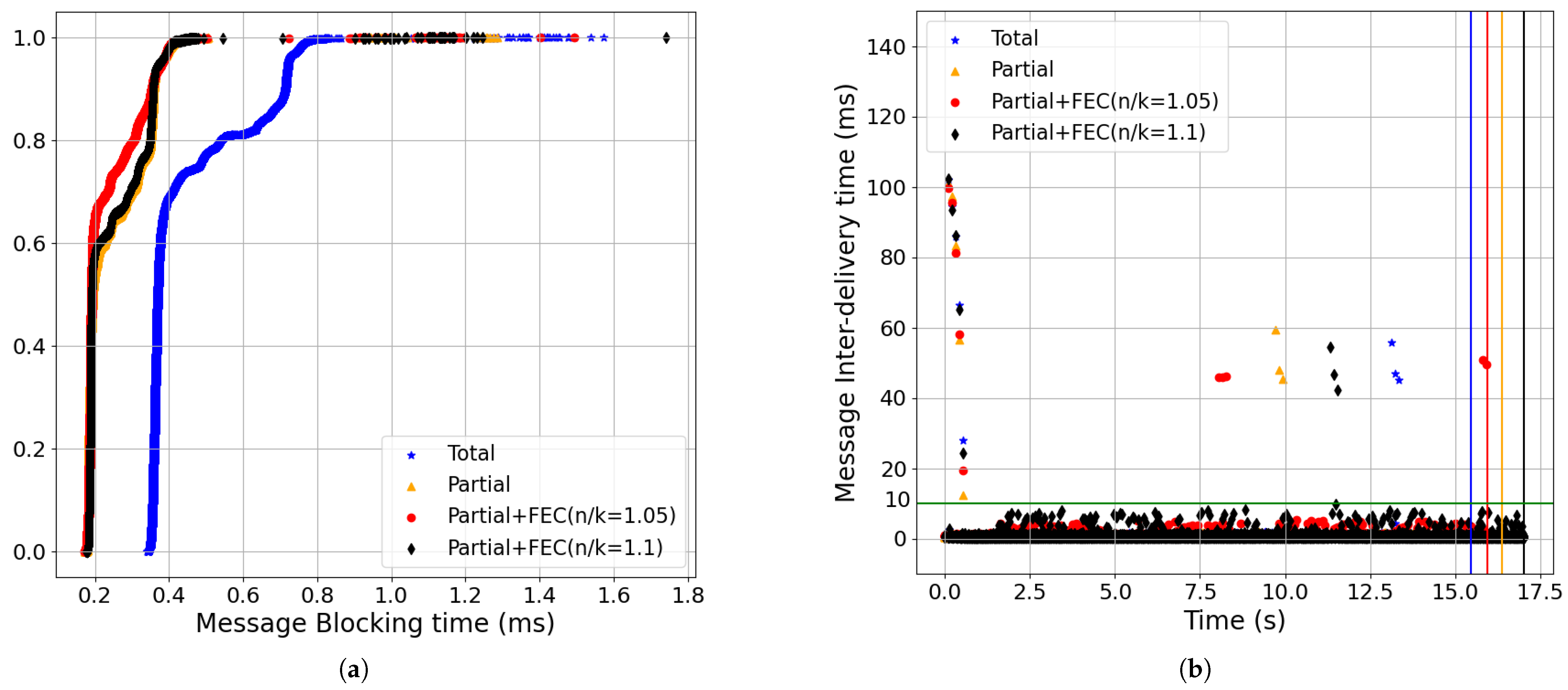
- The latency improvements of Partial+FEC grew as a function of the packet-loss rate for both the streaming and non-streaming workloads. Higher packet-loss rates mean waiting for retrasnmissions more frequently with total delivery, which hurts the latency metrics. For example, with a 1% packet-loss rate, which is double the baseline loss and streaming workload, the 99-percentile of the message-blocking time for partial+FEC (n/k = 1.1) was 0.4 ms, while the 70-percentile of total was already 99 ms, and the 99-percentile was 264 ms (Figure 11).
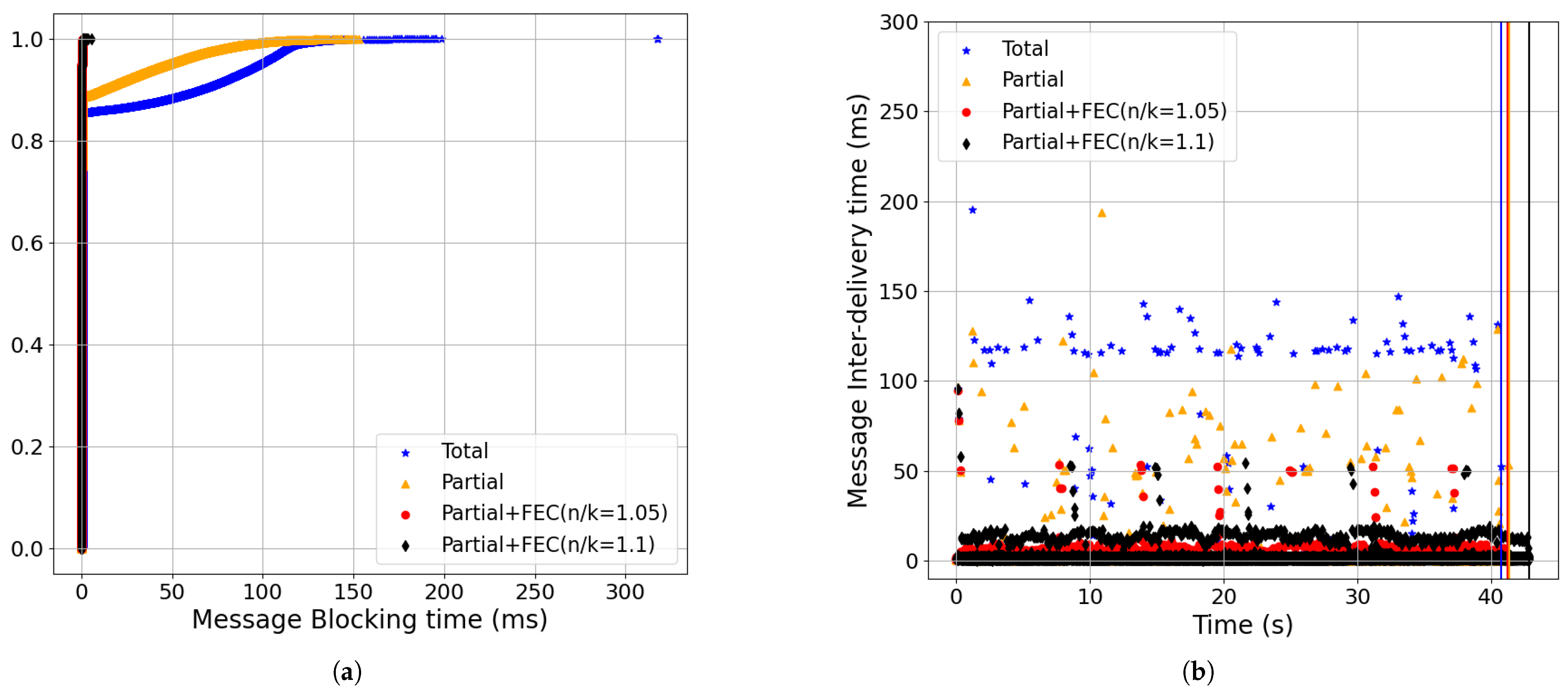
- The latency improvements of Partial+FEC grew as a function of the RTT of the network for both the streaming and non-streaming workloads. A higher RTT means lingering waiting time for each retransmission with total delivery, while using FEC we can let us avoid it. For example, with a 200 ms RTT, which is double the baseline RTT and streaming workload, the 99-percentile of the message-blocking time for partial+FEC (n/k = 1.1) was 0.4 ms, while the 80-percentile of total was already 225 ms, and the 99-percentile was 429 ms (Figure 13).
6.1. Streaming Updates
Discussion of the Results of the Streaming Updates Workload
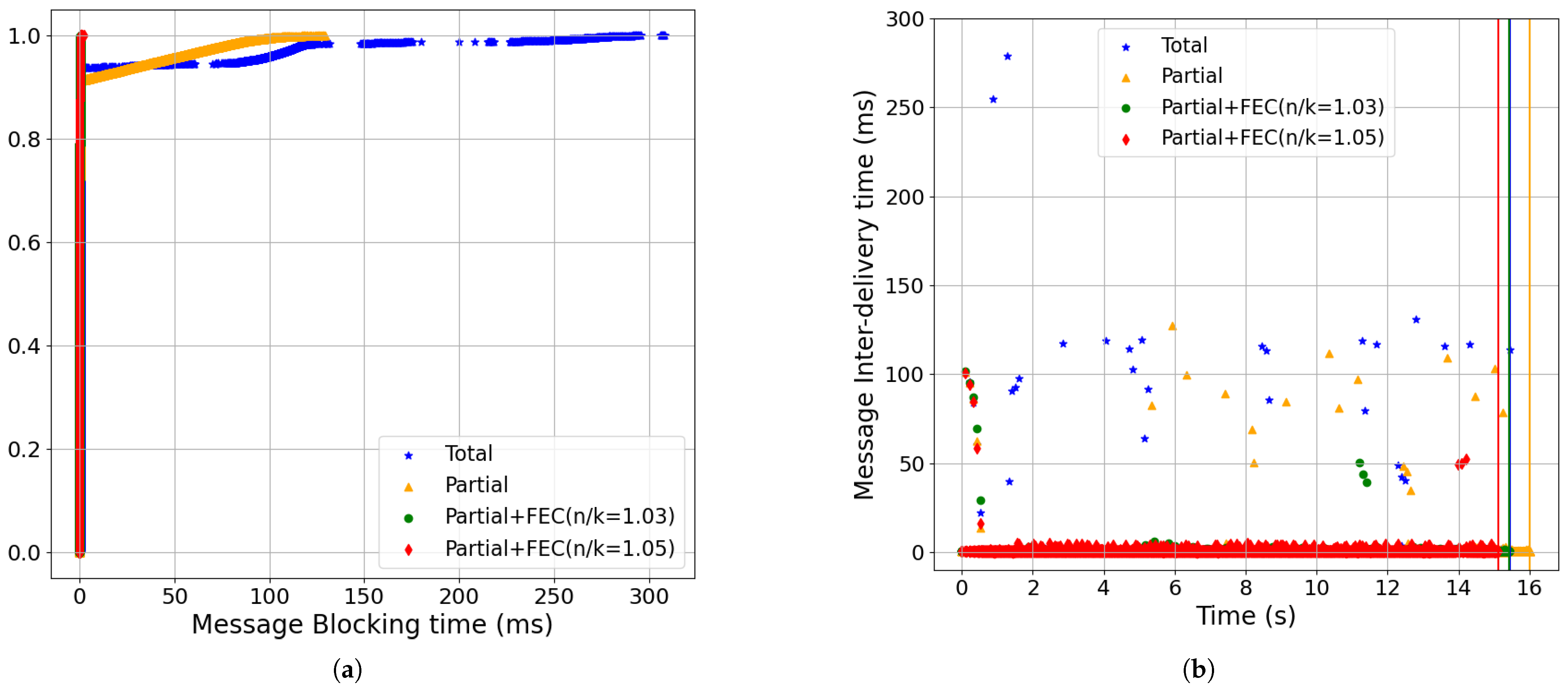
- Partial order+FEC reduced the message-blocking time and inter-delivery time with the baseline setting (Figure 9):In Figure 9a, we show the CDF of the message-blocking time, in which using partial+FEC with both a 5% redundancy rate (i.e., red, n/k = 1.05) and 10% (i.e., black, n/k = 1.1) yielded a 99-percentile time of 0.4 ms. However, the 80-percentile of total (i.e., blue) was already 101.08 ms, and the 99-percentile was 230 ms.Also, in Figure 9b, the total and partial delivery methods had higher message inter-delivery times compared to partial+FEC because they needed to wait for at least an RTT to receive the retransmissions. The 99.95-percentile of the message inter-delivery time was 135 ms for blue, 102 ms for gold, 6 ms for red, and 9 ms for black.
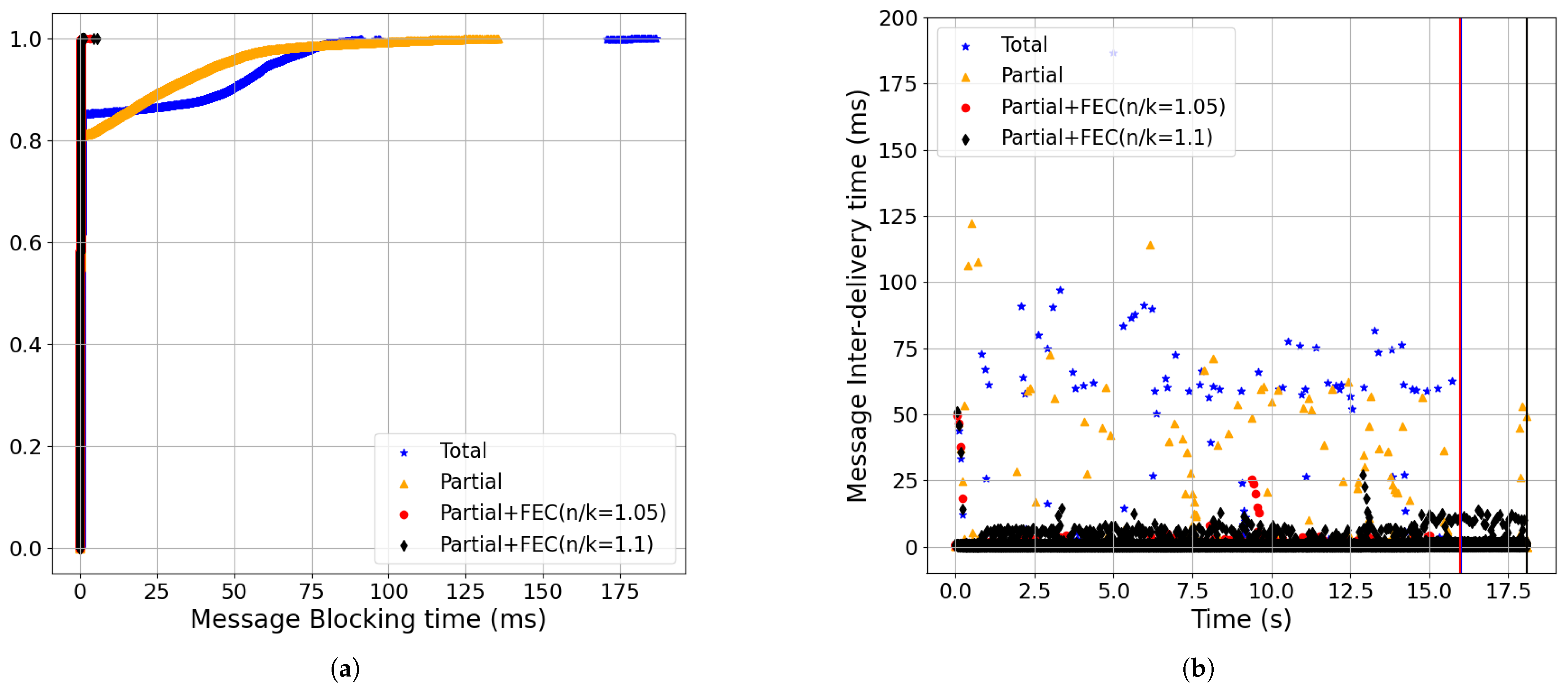
- Partial order+FEC improvements increased as the packet-loss rate and RTT grew (Figure 9, Figure 10, Figure 11, Figure 12 and Figure 13):Increasing packet-loss from 0.1% shown in Figure 10 to 0.5% shown in Figure 9 to 1% shown in Figure 11 show that partial+FEC can result in close to zero message-blocking and message inter-delivery time results even for a 1% packet-loss rate while the latency results became worse for total and partial delivery (i.e., blue and gold). For example, the 70-percentile of the message-blocking time for total shown in Figure 11 was 99.14 ms.Also, as we increased RTT from 50 ms shown in Figure 12 to 100 ms shown in Figure 9 to 200 ms shown in Figure 13, partial+FEC could keep the latency numbers close to zero independent of the RTT, while the message-blocking and message inter-delivery times of total and partial grew as a function of the RTT. For example, the 70-percentile of the message-blocking time for total shown in Figure 13 was 191.88 ms.
- Partial order+FEC improvements remained across different bandwidth values (Figure 9, Figure 14 and Figure 15):Partial+FEC could help reduce both the message-blocking and message inter-delivery times for all three different values of the bandwidth in our experiments, from 10 Mbps shown in Figure 14, to 100 Mbps shown in Figure 9, to 1 Gbps shown in Figure 15. For example, the number of messages with an inter-delivery time higher than 100 ms was 71, 59, and 46 for total v.s. 1 or less for partial+FEC with 10 Mbps shown in Figure 14b, 100 Mbps shown in Figure 9b, and 1 Gbps shown in Figure 15b, respectively.
- Figure 16 shows the message-blocking and message inter-delivery times for CUBIC CCA. Considering the results with BBR and the same other network parameters (i.e., loss, RTT, and bandwidth) shown in Figure 9, we can see the increase in the message inter-delivery time of partial+FEC shown in Figure 16, but these are still better results compared to total and partial delivery. The reason is that we had a smaller congestion window with CUBIC compared to BBR in the case of the packet-loss rate (i.e., 0.5%), so we needed more time to receive the redundant packets at the end of each update to be able to recover lost packets [8].
- The results for the packet-loss rate to set the redundancy rate of partial order+FEC (Figure 17):The amount of redundancy rate depends on the packet-loss rate. We evaluated three values for redundancy rate in our experiments: 1.05 and 1.1 for all of the results except for the 0.1% packet-loss rate shown in Figure 10, with n/k = 1.03 and n/k = 1.05 rates (where n/k = 1.03 is different from the other experiments). Although a high redundancy rate such as 1.1 (i.e., black) yielded close to a 0 message-blocking time for all of the experiments, the redundancy rate of 1.05 (i.e., red) gave the same improvement for the message inter-delivery time as the 1.1 rate and also gave a lower completion time because of lower overhead. Figure 17 shows the FEC overhead with the n/k = 1.05 and n/k = 1.1 rates in terms of the message-blocking and message inter-delivery times when we set the packet-loss rate to 0%. The measured overhead for the message inter-delivery time is less than 10 ms, as seen in Figure 17b.
6.2. Non-Streaming Updates
Discussion of the Results of the Non-Streaming Updates Workload
- Partial order+FEC reduced the message-blocking time and inter-delivery time with the baseline setting (Figure 18):The CDF of the update response time shown in Figure 18a shows that using partial+FEC with 5% redundancy rate (i.e., red, n/k = 1.05), the 99-percentile was 161.82 ms. However, the 99-percentile of total (i.e., blue) was 325.26 ms. Increasing the redundancy rate to 10% (i.e., black, n/k = 1.1) did not make a significant change, as 5% was enough for loss recovery.As shown in Figure 18b, the 99.95-percentile of the message inter-delivery time was 113.5 ms for blue, 97.91 ms for gold, 1.47 ms for red, and 1.79 ms for black. Furthermore, partial+FEC with 5% redundancy completion time was 11 s less than total.
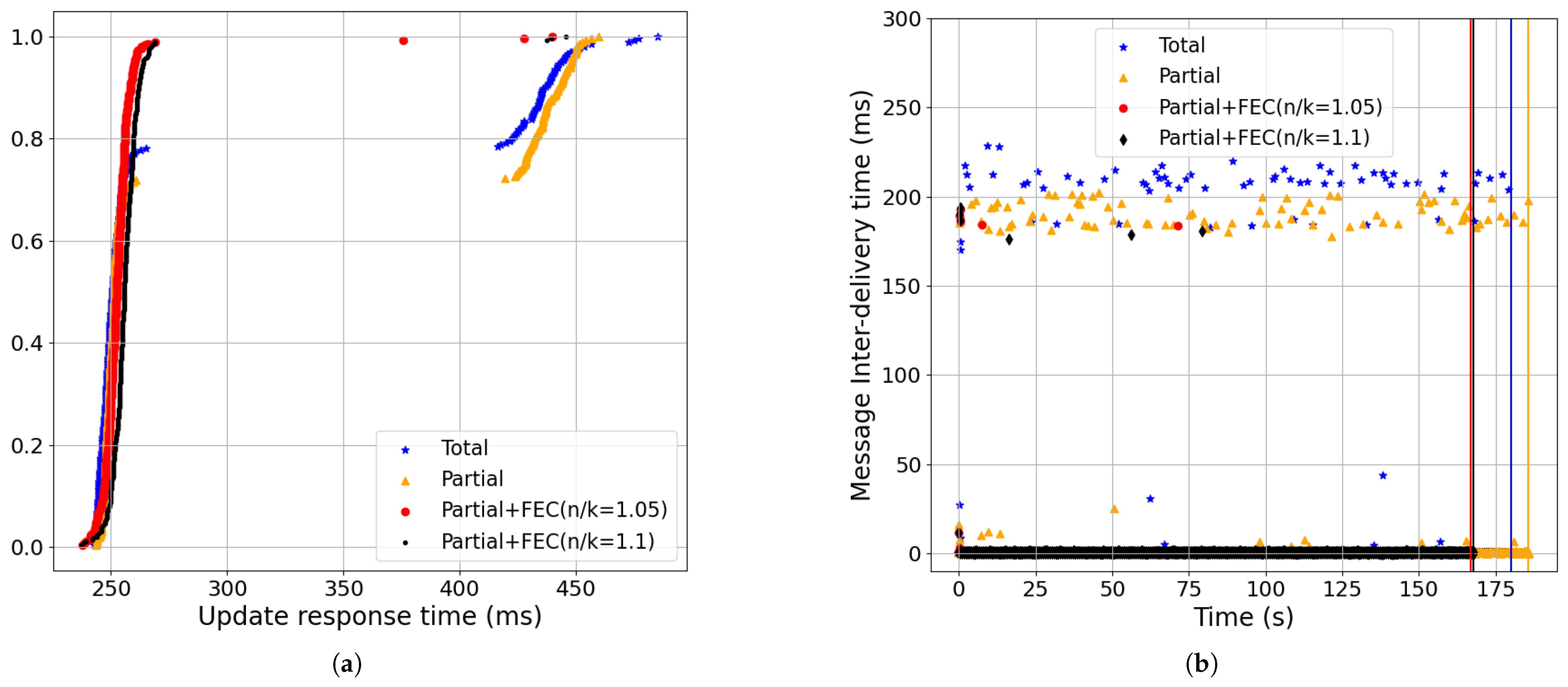
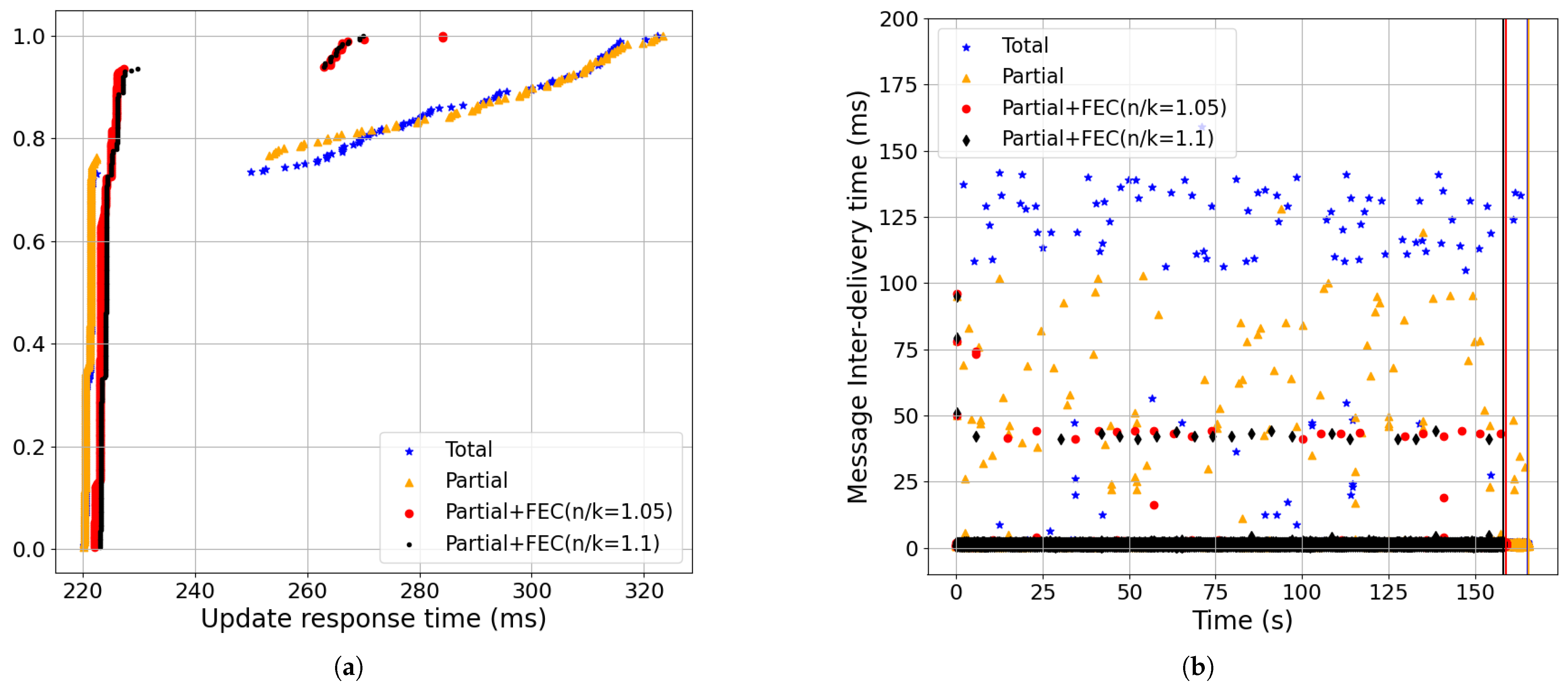
- Partial order+FEC improvements increased as the packet-loss rate and RTT grew (Figure 18, Figure 19, Figure 20, Figure 21 and Figure 22):Increasing packet-loss rate from 0.1% shown in Figure 19 to 0.5% shown in Figure 18 to 1% shown in Figure 20 showed greater improvements in partial+FEC for both the update response and message inter-delivery times. For example, as shown in Figure 20, the 99-percentile of the update response time was 164.19 ms for partial+FEC with 10% redundancy rate (i.e., black, n/k = 1.1), 316.94 ms for Partial+FEC (n/k = 1.05, red), 318.02 ms for partial (i.e., gold), and 319.88 ms for total (i.e., blue). The 5% redundancy rate of Partial+FEC (n/k = 1.05) caused a lower recovery rate compared to Partial+FEC (n/k = 1.1) with a high packet-loss rate of 1%.Also, as we increased RTT from 50 ms shown in Figure 21 to 100 ms shown in Figure 18 to 200 ms shown in Figure 22, partial+FEC could reduce the update response time and message inter-delivery time as a function of the RTT compared to total and partial delivery. For example, as shown in Figure 22, the 99-percentile of the update response time was 272 ms for both partial+FEC (n/k = 1.05) and partial+FEC (n/k = 1.1), while it was 422 ms for total delivery.
- Partial order+FEC improvements remained across different bandwidth values (Figure 18, Figure 23, and Figure 24):Partial+FEC could help reduce both the update response and message inter-delivery time for all three different values of bandwidth in our experiments, from 10 Mbps shown in Figure 23, to 100 Mbps shown in Figure 18, to 1 Gbps shown in Figure 24. For example, the number of messages with an inter-delivery time higher than 100 ms was 79, 61, and 72 for total v.s. 2 or less for partial+FEC with 10 Mbps shown in Figure 14b, 100 Mbps shown in Figure 9b, and 1 Gbps shown in Figure 15b, respectively.
- Figure 25 shows the update response and message inter-delivery time for CUBIC CCA. Considering the results with BBR and the same other network parameters (i.e., loss, RTT, and bandwidth) in Figure 18, we can see the increase in the message inter-delivery time of partial+FEC in Figure 25 but still with better results compared to total and partial delivery. For example, the number of points above 100 ms is 68 for blue, 13 for gold, 0 for red, and 0 for black in Figure 25b.
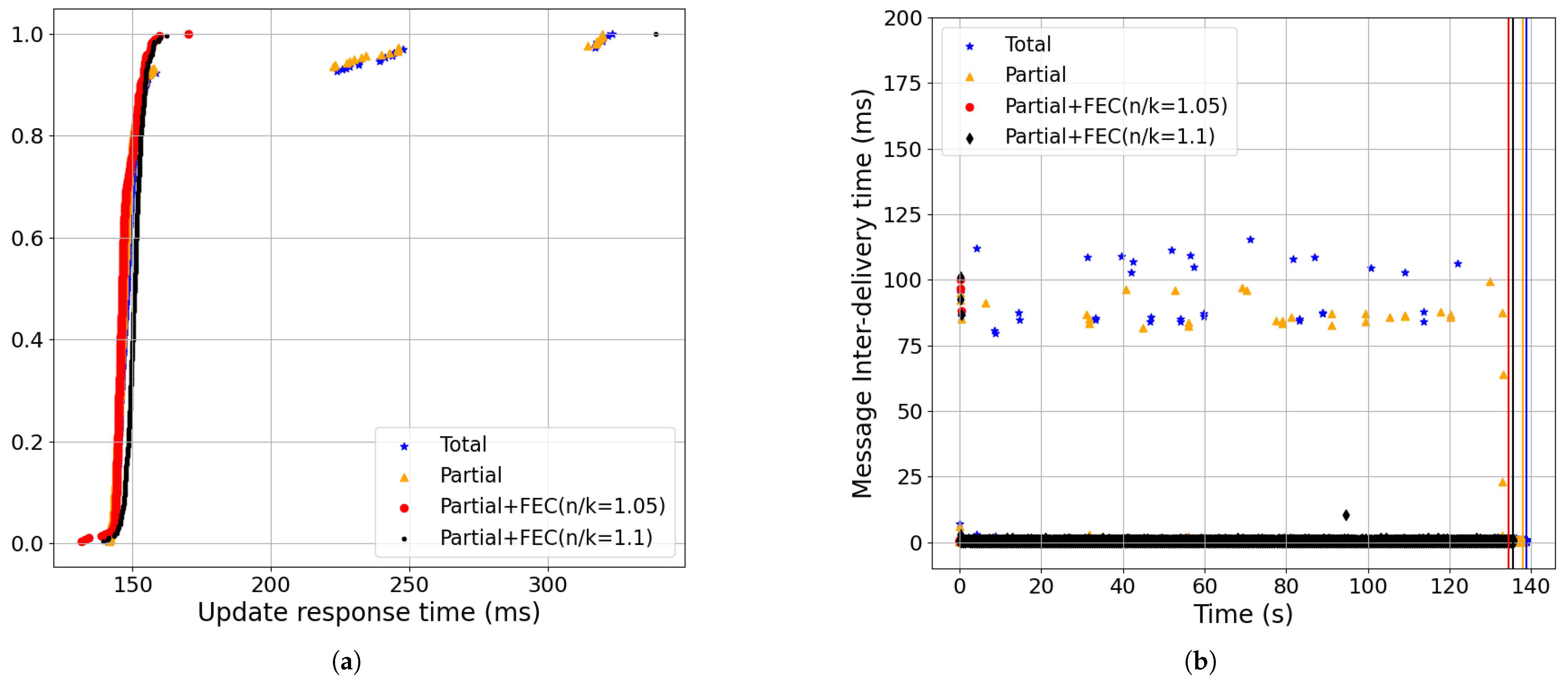
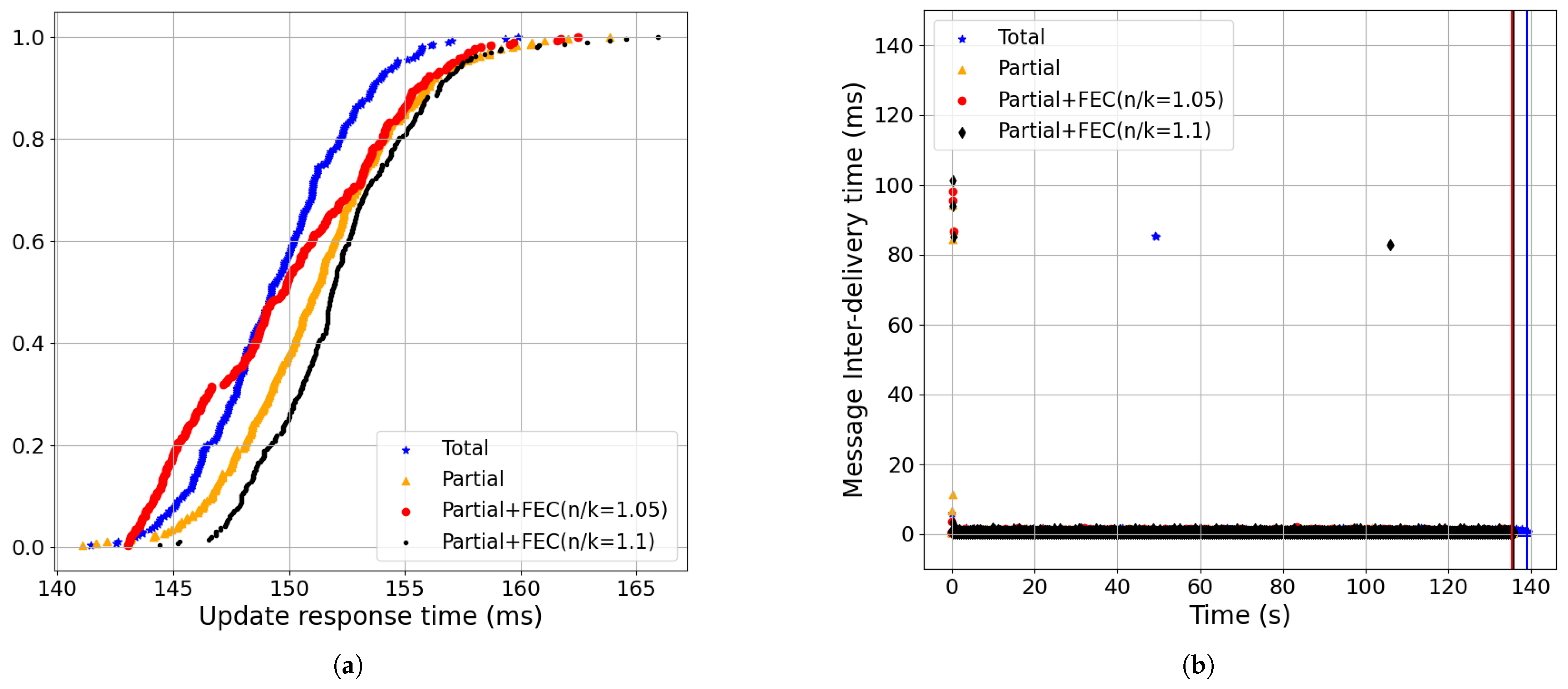
- FEC Overhead:Figure 26 shows the FEC overhead with n/k = 1.05 and n/k = 1.1 rates in terms of update response and message inter-delivery time as we set the packet-loss rate to 0%. Partial+FEC had no considerable negative impact on latency, especially with n/k = 1.05. Comparing Figure 26b and Figure 17b shows that the FEC overhead had less impact on the latency of the non-streaming workload. The reason is that since there was a 300 ms gap between every two consecutive updates in non-streaming, the overhead of FEC for each update did not have an impact on the next update.
7. Concluding Remarks
Author Contributions
Funding
Data Availability Statement
Acknowledgments
Conflicts of Interest
References
- Connolly, T.; Amer, P.; Conrad, P. An Extension to TCP: Partial Order Service; Internet RFC1693; 1994. Available online: https://datatracker.ietf.org/doc/html/rfc1693 (accessed on 18 June 2025).
- McKusick, M.K.; Quinlan, S. GFS: Evolution on Fast-forward: A discussion between Kirk McKusick and Sean Quinlan about the origin and evolution of the Google File System. Queue 2009, 7, 10–20. [Google Scholar] [CrossRef]
- Pooya, S.; Lu, P.; MacGregor, M.H. Structured Message Transport. In Proceedings of the 2012 IEEE 31st International Performance Computing and Communications Conference (IPCCC), Austin, TX, USA, 1–3 December 2012; pp. 432–439. [Google Scholar]
- Eghbal, N.; Lu, P. Consistency Fences for Partial Order Delivery to Reduce Latency. In Proceedings of the International Conference on Computational Science, Omaha, NE, USA, 27–29 June 2022; Springer: Cham, Switzerland, 2022; pp. 488–501. [Google Scholar]
- Mosberger, D. Memory consistency models. ACM SIGOPS Oper. Syst. Rev. 1993, 27, 18–26. [Google Scholar] [CrossRef]
- Gu, Y.; Grossman, R.L. UDT: UDP-based data transfer for high-speed wide area networks. Comput. Netw. 2007, 51, 1777–1799. [Google Scholar] [CrossRef]
- Langley, A.; Riddoch, A.; Wilk, A.; Vicente, A.; Krasic, C.; Zhang, D.; Yang, F.; Kouranov, F.; Swett, I.; Iyengar, J.; et al. The quic transport protocol: Design and internet-scale deployment. In Proceedings of the Conference of the ACM Special Interest Group on Data Communication, Los Angeles, CA, USA, 21–25 August 2017; pp. 183–196. [Google Scholar]
- Eghbal, N.; Ciotto Pinton, G.; Muthuraj, N.; Lu, P. Quic-Sfec: Lower Latency Quic for Resource Dependencies Using Forward Error Correction. preprint. [CrossRef]
- OpenFEC. 2025. Available online: http://openfec.org/ (accessed on 18 June 2025).
- Stewart, R.; Metz, C. SCTP: New transport protocol for TCP/IP. IEEE Internet Comput. 2001, 5, 64–69. [Google Scholar] [CrossRef]
- List of QUIC Implementation. 2025. Available online: https://github.com/quicwg/base-drafts/wiki/Implementations (accessed on 18 June 2025).
- ngtcp2. ngtcp2 Project Is an Effort to Implement IETF QUIC Protocol. 2025. Available online: https://github.com/ngtcp2/ngtcp2 (accessed on 18 June 2025).
- nghttp3. HTTP/3 Library Written in C. 2025. Available online: https://github.com/ngtcp2/nghttp3 (accessed on 18 June 2025).
- Sundararajan, J.K.; Shah, D.; Médard, M.; Mitzenmacher, M.; Barros, J. Network coding meets TCP. In Proceedings of the IEEE INFOCOM 2009, Rio de Janeiro, Brazil, 19–25 April 2009; pp. 280–288. [Google Scholar]
- Kim, M.; Cloud, J.; ParandehGheibi, A.; Urbina, L.; Fouli, K.; Leith, D.; Médard, M. Network Coded tcp (ctcp). arXiv 2012, arXiv:1212.2291. [Google Scholar]
- Hamilton, R.; Iyengar, J.; Swett, I.; Wilk, A. QUIC: A UDP-Based Secure and Reliable Transport for HTTP/2. Internet-Draft draft-hamilton-early-deployment-quic-00; 2016. Available online: https://datatracker.ietf.org/doc/html/draft-tsvwg-quic-protocol-02 (accessed on 18 June 2025).
- Kakhki, A.M.; Jero, S.; Choffnes, D.; Nita-Rotaru, C.; Mislove, A. Taking a long look at QUIC: An approach for rigorous evaluation of rapidly evolving transport protocols. In Proceedings of the 2017 Internet Measurement Conference, London, UK, 1–3 November 2017; pp. 290–303. [Google Scholar]
- Garrido, P.; Sanchez, I.; Ferlin, S.; Aguero, R.; Alay, O. rQUIC: Integrating FEC with QUIC for robust wireless communications. In Proceedings of the 2019 IEEE Global Communications Conference (GLOBECOM), Waikoloa, HI, USA, 9–13 December 2019; pp. 1–7. [Google Scholar]
- Michel, F.; De Coninck, Q.; Bonaventure, O. QUIC-FEC: Bringing the benefits of Forward Erasure Correction to QUIC. In Proceedings of the IEEE 2019 IFIP Networking Conference (IFIP Networking), Warsaw, Poland, 20–22 May 2019; pp. 1–9. [Google Scholar]
- Michel, F.; Cohen, A.; Malak, D.; De Coninck, Q.; Médard, M.; Bonaventure, O. FlEC: Enhancing QUIC with application-tailored reliability mechanisms. IEEE/ACM Trans. Netw. 2022, 31, 606–619. [Google Scholar] [CrossRef]
- Michel, F.; Bonaventure, O. QUIRL: Flexible QUIC Loss Recovery for Low Latency Applications. IEEE/ACM Trans. Netw. 2024, 32, 5204–5215. [Google Scholar] [CrossRef]
- Holzinger, K.; Petri, D.; Lachnit, S.; Kempf, M.; Stubbe, H.; Gallenmüller, S.; Günther, S.; Carle, G. Forward Error Correction and Weighted Hierarchical Fair Multiplexing for HTTP/3 over QUIC. In Proceedings of the IEEE 2025 IFIP Networking Conference (IFIP Networking), Limassol, Cyprus, 26–29 May 2025; pp. 1–9. [Google Scholar]
- Richardson, T.; Stafford-Fraser, Q.; Wood, K.R.; Hopper, A. Virtual network computing. IEEE Internet Comput. 1998, 2, 33–38. [Google Scholar] [CrossRef]
- Richardson, T.; Wood, K.R. The rfb Protocol; ORL: Cambridge, UK, 1998. [Google Scholar]
- TigerVNC. TigerVNC Project. Available online: https://www.tigervnc.org (accessed on 18 June 2025).
- Marx, R.; De Decker, T.; Quax, P.; Lamotte, W. Resource Multiplexing and Prioritization in HTTP/2 over TCP Versus HTTP/3 over QUIC. In Proceedings of the Web Information Systems and Technologies: 15th International Conference, WEBIST 2019, Vienna, Austria, 18–20 September 2019; Revised Selected Papers 15; Springer: Cham, Switzerland, 2020; pp. 96–126. [Google Scholar]
- Hasselquist, D.; Lindström, C.; Korzhitskii, N.; Carlsson, N.; Gurtov, A. Quic throughput and fairness over dual connectivity. Comput. Netw. 2022, 219, 109431. [Google Scholar] [CrossRef]
- Endres, S.; Deutschmann, J.; Hielscher, K.S.; German, R. Performance of QUIC implementations over geostationary satellite links. arXiv 2022, arXiv:2202.08228. [Google Scholar]
- Oku, K.; Pardue, L. Extensible Prioritization Scheme for HTTP; Work Progress, Internet-Draft. Draft-Ietfhttpbis; 2020; Volume 1. Available online: https://datatracker.ietf.org/doc/rfc9218/ (accessed on 18 June 2025).
- Mittal, R.; Shpiner, A.; Panda, A.; Zahavi, E.; Krishnamurthy, A.; Ratnasamy, S.; Shenker, S. Revisiting network support for RDMA. In Proceedings of the 2018 Conference of the ACM Special Interest Group on Data Communication, Budapest, Hungary, 20–25 August 2018; pp. 313–326. [Google Scholar]
- Emulab. 2025. Available online: https://www.emulab.net (accessed on 18 June 2025).
- White, B.; Lepreau, J.; Stoller, L.; Ricci, R.; Guruprasad, S.; Newbold, M.; Hibler, M.; Barb, C.; Joglekar, A. An Integrated Experimental Environment for Distributed Systems and Networks. In Proceedings of the Fifth Symposium on Operating Systems Design and Implementation, USENIX Association, Boston, MA, USA, 9–11 December 2002; pp. 255–270. [Google Scholar]
- Eghbal, N. Emulab Profile. Available online: https://github.com/nEghbal/netem_dummynet/blob/main/profile.py (accessed on 18 June 2025).
- Dummynet. 2025. Available online: https://man.freebsd.org/cgi/man.cgi?dummynet (accessed on 18 June 2025).
- Sander, C.; Kunze, I.; Wehrle, K. Analyzing the Influence of Resource Prioritization on HTTP/3 HOL Blocking and Performance. In Proceedings of the 2022 Network Traffic Measurement and Analysis Conference (TMA), Enschede, The Netherlands, 27–30 June 2022; pp. 1–10. [Google Scholar]
- Zeldovich, N.; Chandra, R. Interactive Performance Measurement with VNCPlay. In Proceedings of the USENIX Annual Technical Conference, FREENIX Track, Anaheim, CA, USA, 10–15 April 2005; pp. 189–198. [Google Scholar]


| Parameter | Value |
| Workload | streaming updates, non-streaming updates |
| Packet loss | 0%, 0.1%, 0.5%, 1% |
| RTT | 50 ms, 100 ms, 200 ms |
| Bandwidth | 10 Mbps, 100 Mbps, 1 Gbps |
| CCA | BBR, CUBIC |
| QUIC frame size | 1400 B |
Disclaimer/Publisher’s Note: The statements, opinions and data contained in all publications are solely those of the individual author(s) and contributor(s) and not of MDPI and/or the editor(s). MDPI and/or the editor(s) disclaim responsibility for any injury to people or property resulting from any ideas, methods, instructions or products referred to in the content. |
© 2025 by the authors. Licensee MDPI, Basel, Switzerland. This article is an open access article distributed under the terms and conditions of the Creative Commons Attribution (CC BY) license (https://creativecommons.org/licenses/by/4.0/).
Share and Cite
Eghbal, N.; Lu, P. Lower-Latency Screen Updates over QUIC with Forward Error Correction. Future Internet 2025, 17, 297. https://doi.org/10.3390/fi17070297
Eghbal N, Lu P. Lower-Latency Screen Updates over QUIC with Forward Error Correction. Future Internet. 2025; 17(7):297. https://doi.org/10.3390/fi17070297
Chicago/Turabian StyleEghbal, Nooshin, and Paul Lu. 2025. "Lower-Latency Screen Updates over QUIC with Forward Error Correction" Future Internet 17, no. 7: 297. https://doi.org/10.3390/fi17070297
APA StyleEghbal, N., & Lu, P. (2025). Lower-Latency Screen Updates over QUIC with Forward Error Correction. Future Internet, 17(7), 297. https://doi.org/10.3390/fi17070297