1. Introduction
The desire to improve the performance of manufacturing processes led to the emergence of many novel approaches to keep up with the rapidly evolving world of robotics, one of them being Cloud Robotics [
1]. Moving computationally intensive tasks to the cloud enhances a system’s performance and computational capabilities, mitigating the known limitations of robotic devices (some notable examples being limited storage and on-board computation, as well as battery and storage capacities) while offering a way of sharing services [
2].
In our previous article [
3], we utilized a digital twin [
4] from ABB RobotStudio in order to test the performance of our proposed solution in a simulated environment before implementing it on the real robot. In this article, we take the proposed architecture from our previous work and compare the results we obtained there in Robot Studio with the results we have obtained now, in the real world, using the ABB IRB 140 industrial robot. We compare the performance obtained with the proposed method, based on Custom Vision, with a commercial machine vision software used in industrial applications. Custom Vision is part of Microsoft Azure’s AI services and it allows users to create, train, and evaluate their own models for image classification or object detection and recognition. We particularly suggest this method as a fallback option for cases where specialized machine vision software is unable to detect objects, such as when they are dirty or overlapping.
2. Literature Review
Various types of AI techniques are being used by the scientific community for classification and detection tasks [
5,
6,
7]. In the study of [
8], cloud technology was used in a face recognition application based on Deep Learning algorithms in order to improve speed and overcome robot onboard limitations. The authors encrypted the images used for training and testing, and tested several deep learning algorithms for training in order to measure and compare the security, time complexity, and accuracy of recognition for algorithms in the cloud and on robots, obtaining the overall best security and recognition accuracy with the genetic algorithm. Their results show that by using the cloud environment, compared to performing the same computation for the same algorithm directly on the robot, the recognition time decreased from 0.559 s to 0.014 s, and the performance of the algorithm was maintained. Therefore, this paper showcases the cloud’s ability to decrease the computation time of resource-intensive robotics tasks.
The study [
9] presents an autonomous pick-and-sort operation in industrial cloud robotics based on object recognition and motion planning. The object recognition uses a CNN, and to perform the training, cloud computing resources were utilized to meet the high computational resource needs. The CNN method, compared to a CG algorithm, improved the object recognition time by a factor of ten. This application has a similar use case to ours, since they are also executing a pick-and-sort operation using an industrial robot. Their results showed that for a mean inter-object spawning time of 14 s and a mean service time needed for the robot arm to perform the movement of 13 sec, the pick-and-sort operation could reach an overall success rate 71.3%.
CNNs have been used in the fields of artificial vision, object recognition, and natural language processing with exceptional performance. Created based on natural vision systems and neurons, this NN can extract features from data, like images and videos, employing convolutional computations and pooling operations. As one of the main algorithms of deep learning, CNNs are composed of five layers: data input, convolutional computation, activation function, pooling and fully connected layer. In the first layer, the image is preprocessed for speeding up the operations performed in the next layers. The convolutional computation layer is the principal layer in feature extraction, performing several convolution computations to extract various input features. Next, the activation function layer uses numerous activation functions, such as ReLU, ELU, SELU, Sigmoid, Tanh, and many others to map the outputs of the convolutional layer. Then, to reduce the number of features while maintaining the key features, the pooling layer is used. Finally, by modifying parameters and weights, the fully connected layer converts the bidimensional feature map, produced by convolution, into a unidimensional vector, which represents the desired information [
10].
To obtain such a CNN, one must train it, which is a time-consuming and a computationally and energy-intensive process that usually takes place using expensive computational resources, like GPUs, which aid this process by parallelization to reduce training time and costs. CNN training presumes a fine-tuning of the layers’ internal parameters, known as weights, that determine the layers’ outputs and is accomplished in multiple iterations, involving forward passes and backpropagation, loss computations, optimizer updates, and data transmission between the host memory and the GPU. When performing the training, images are processed in batches, the quantity of images processed in a single iteration is called mini-batch size, and precisely one processing of all training images forms a training epoch. The training of NNs is not an easy feat and researchers are working continuously to better estimate CNN training time and improve network generalization and recognition abilities [
11,
12].
Cloud computing plays an important role in future Internet-based solutions, supporting the evolution of technology through innovations such as the development of smart cities [
13] or collaborative computing [
14]. We see that various cloud-based solutions are being approached by researchers for various robotics applications, at different levels of the architecture, while at the same time, effort is being put into improving resources [
15]; workload balancing abilities [
16]; the mitigation of security vulnerabilities, like threats and attacks [
17], to provide information security when accessing information from the cloud [
18]; cloud scalability and latency [
19]; and the consistency of connectivity of the cloud.
In particular, the study of [
20] focused on improving the load balancing abilities of the cloud. They propose a solution to increase the computation performance and resource usage efficiency of the platform by enhancing the resources management module with the use of a flexible container capacity scheduling algorithm. The algorithm performs capacity elastic scheduling operations based on the usage of CPU, memory, and network of the containers. This paper shows how consistent research efforts channeled towards the load-balancing abilities of the cloud while multiple robots have access to the cloud service on demand, could increase the collaborative capabilities of robots.
Another area which is receiving attention is the consistency of connectivity. For example, in [
21], an IoRT and cloud robotics solution is proposed based on a three-level client server architecture. Django was utilized for the development of the AWS Cloud hosted application, demonstrating real-time, bidirectional communication capabilities. The authors evaluated the solutions for multiple physical and simulated robots and obtained good capabilities for long-distance global remote control and monitoring using the Internet, while confirming the robustness of the framework, and obtaining minimal communication delays with superior performance in both local and cloud environments.
The study of [
22] discusses advancements in addressing issues such as low latency, the scalability of data storage, computation, and resource management efficiency through the incorporation of AI-based optimization, cloud services and workload management strategies to enhance the Internet-driven applications.
As the capabilities of cloud platforms increase and further improvements are made regarding their resources, workload balancing ability, and the consistency of connectivity between users or devices, we expect to see them integrated in robotics solutions increasingly often.
In the remainder of this paper, we will present the constituent components of our architecture, how the implementation was achieved, the results obtained for two illumination conditions (natural light vs. artificial light) and for both solutions (the proposed solution based on Custom Vision vs. the industrial machine vision software), and our conclusions after analyzing the results.
3. Materials and Methods
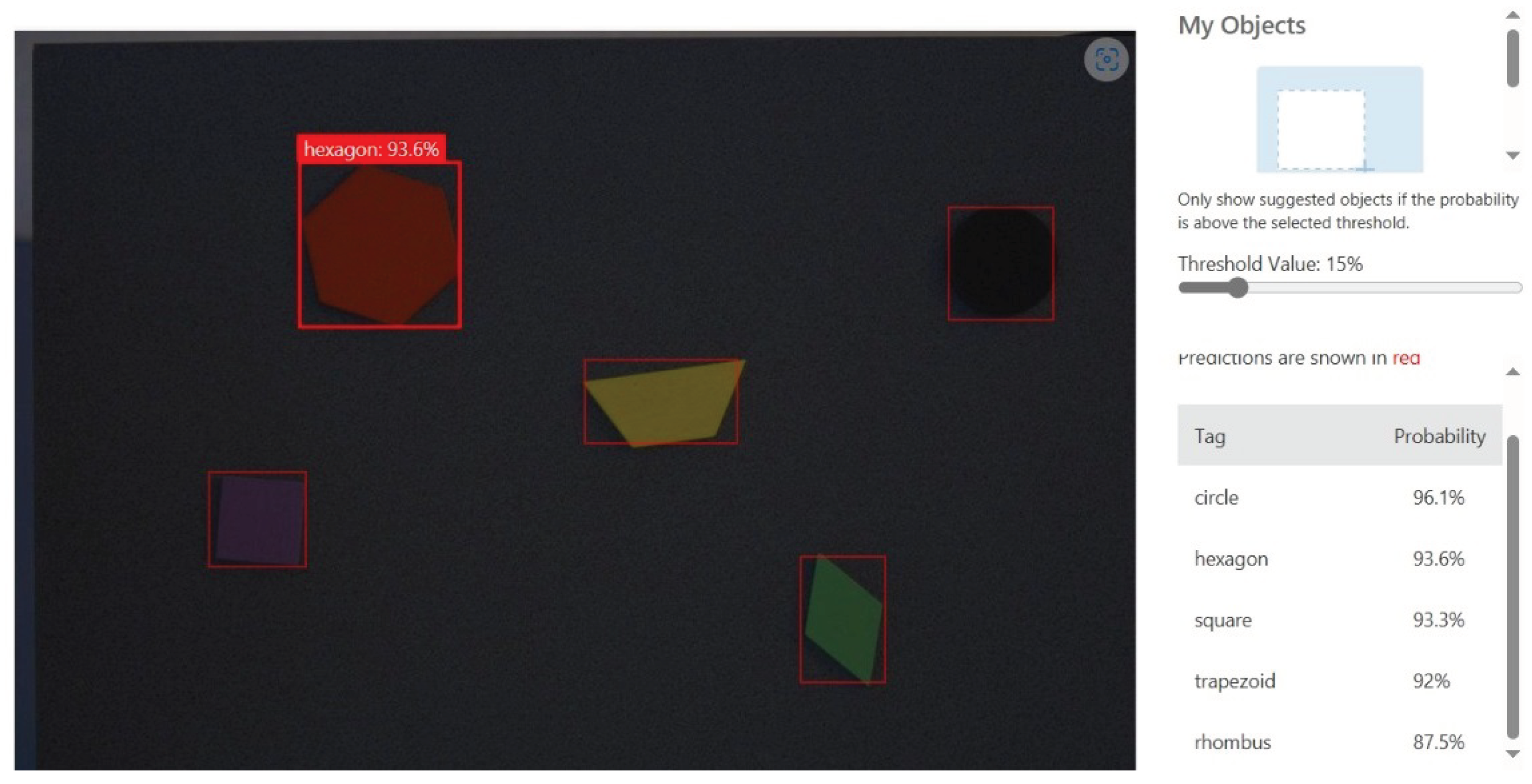
Our suggested solution for the sorting task incorporates Microsoft Azure Custom Vision, a cloud service that enables the localization (obtaining the position) and identification (obtaining the type) of items in a picture using a user-created custom model. The position is denoted by a bounding box in which the object is contained, and the type is represented by a tag and a detection confidence returned by the service. The model was trained using 40 images, taken by a camera in good illumination conditions, with plenty of natural light, of 5 objects of different shapes and colors (a black circle with a radius of 16.5 mm; a purple square with sides of 25 mm; a green rhombus with sides of 25 mm; two yellow trapezoids with bases measuring 50 mm and 25 mm, respectively; and a red hexagon with sides of 25 mm), placed in different positions and orientations. The training is performed by assigning bounding boxes and tags for the objects present in the training images, and then an ONNX model is computed by the service. The result of the training process can be seen in
Figure 1.
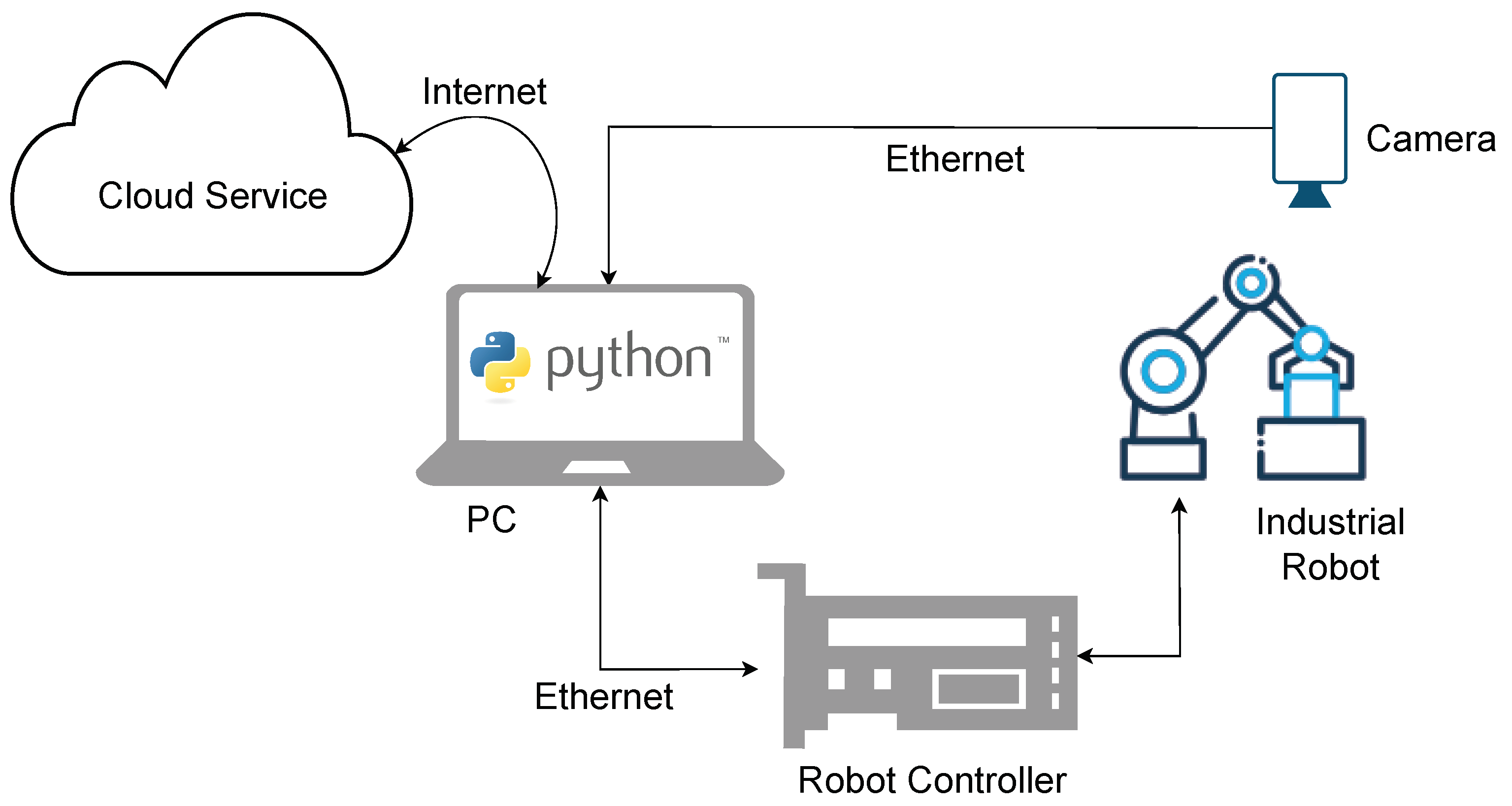
The layout of the system is made up of an industrial robot, an IRB 140 from ABB, a vision system, an Ace2 R a2A2590-22gcBAS [
23] camera from Basler with a C125-1620-5M f16mm lens [
24], the Microsoft Azure Custom Vision cloud service, and a computer that acts as an interface between the previously mentioned components, as shown in
Figure 2. The same system is presented in
Figure 3a, where the vacuum suction gripper used for manipulating the objects is highlighted.
The computer is the centerpiece of the system. It runs a Python script that connects to the camera via a GigE connection, using the Basler pyPylon wrapper and requests images from the camera. The vision system, upon receiving a request, takes a picture and sends it back to the computer, where the same Python script creates a connection to the cloud and sends the pictures to Microsoft Azure Custom Vision over an API, and then awaits a response. When the cloud service API response is received, it is processed and transmitted to the robot arm–robot controller pair for the sorting process.
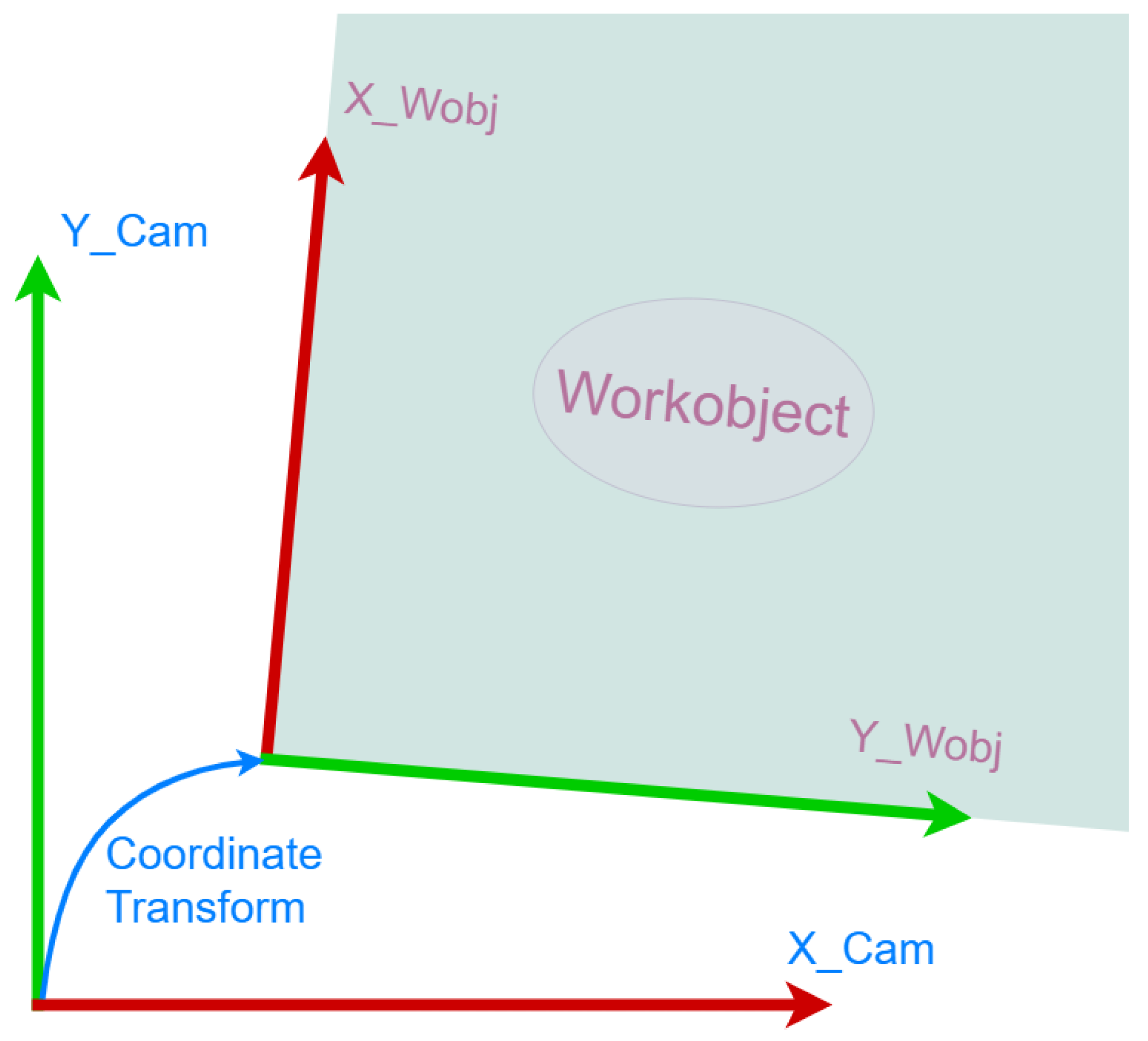
Azure AI Custom Vision provides an API answer in JSON format that includes the kind of item identified, the position, indicated by a bounding box, and the detection probability. Following camera calibration, the object location in camera frame, in millimeters, is calculated using the pixel-to-millimeter ratio. Applying a coordinate system transform (
Figure 3b), the position of the handling point in the robot frame is obtained and finally transmitted to the robot controller over the Ethernet connection by the Python script. The coordinate system (P1P3P2) for robot–camera calibration is adjusted in the vision system based on the points that are learned with the robot. For this, a special target (arrow) is used. The event diagram for the whole procedure can be seen in
Figure 4.
Experiments were conducted through a material handling task executed by the already introduced industrial robot, which uses guidance information from two sources:
- 1.
The proposed machine vision service;
- 2.
A commercial machine vision software, namely MVTec Merlic.
Both vision systems use the same acquisition solution, namely a fixed network industrial camera (the GIGE type from Basler) that inspects the vision plane. The handling principle, presented in (
Figure 3b), uses the concept of workobject which is a reference frame used to define the position and orientation of a workpiece or fixture in space. In our case, the workobject is in the vision plane. The robot–camera or hand–eye calibration (ref) consists of the following:
- 1.
Aligning the axis of the vision plane with the axis of the robot workobject;
- 2.
Overlaying the origin.
In this respect, after applying the camera calibration described by the translation vector
, the rotation matrix
(Equations (
1) and (
2)) and the pixel to mm ratio of
, which transform the position from the camera coordinates to the workobject coordinates, as illustrated in
Figure 5, the vision system offers information in mm about the location of the recognized handled object in the learned workobject. This information is used to perform the handling of the object.
The workobject is defined by the translation vector
t and the rotation quaternions
q, as seen in Equation (
3). The transformation matrix
T is computed as Equation (
4) and can be used to transform a point from the vision plane to the robot plane as shown in Equation (
5), where
is the point in the vision plane, and
is the point in the robot plane. The inverse operation can be performed as in Equation (
6) using the inverse of the transformation matrix
, as seen in Equation (
7).
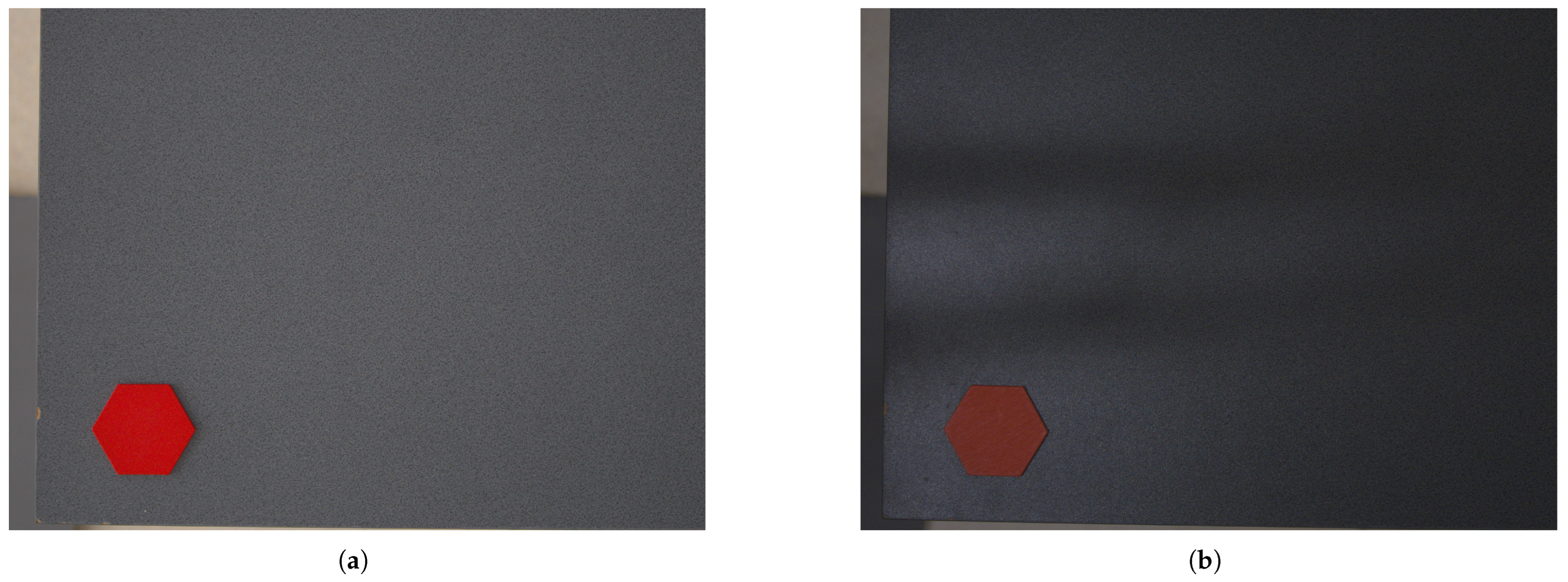
The experiments consist of evaluating robot-vision accuracy through both methods, Microsoft Azure Custom Vision and MVTec Merlic, and then comparing the results to see how the cloud service performs against industrial solutions. A robot trajectory, which uses 12 points on the vision plane, was implemented. The robot put the test target (which can be one of the five objects) on the vision plane and the coordinates were stored. The target was left on the vision plane, and its position was computed using the vision system. The image processing time was also measured at the consumer side, from the time a command was issued to the moment the result was received (i.e., from the time the image was sent to the cloud to the moment the results were received). For each object, 12 experiments were performed, under different illuminations, first in similar conditions to the images used for training, i.e., with natural light and then under artificial light. The difference in lighting can be seen in
Figure 6 Comparative results are illustrated in the next section.
4. Results
The position of the objects, which are compared in this section, represents the center of the bounding box containing the objects, as seen in
Figure 7, and is also the picking point for handling the object.
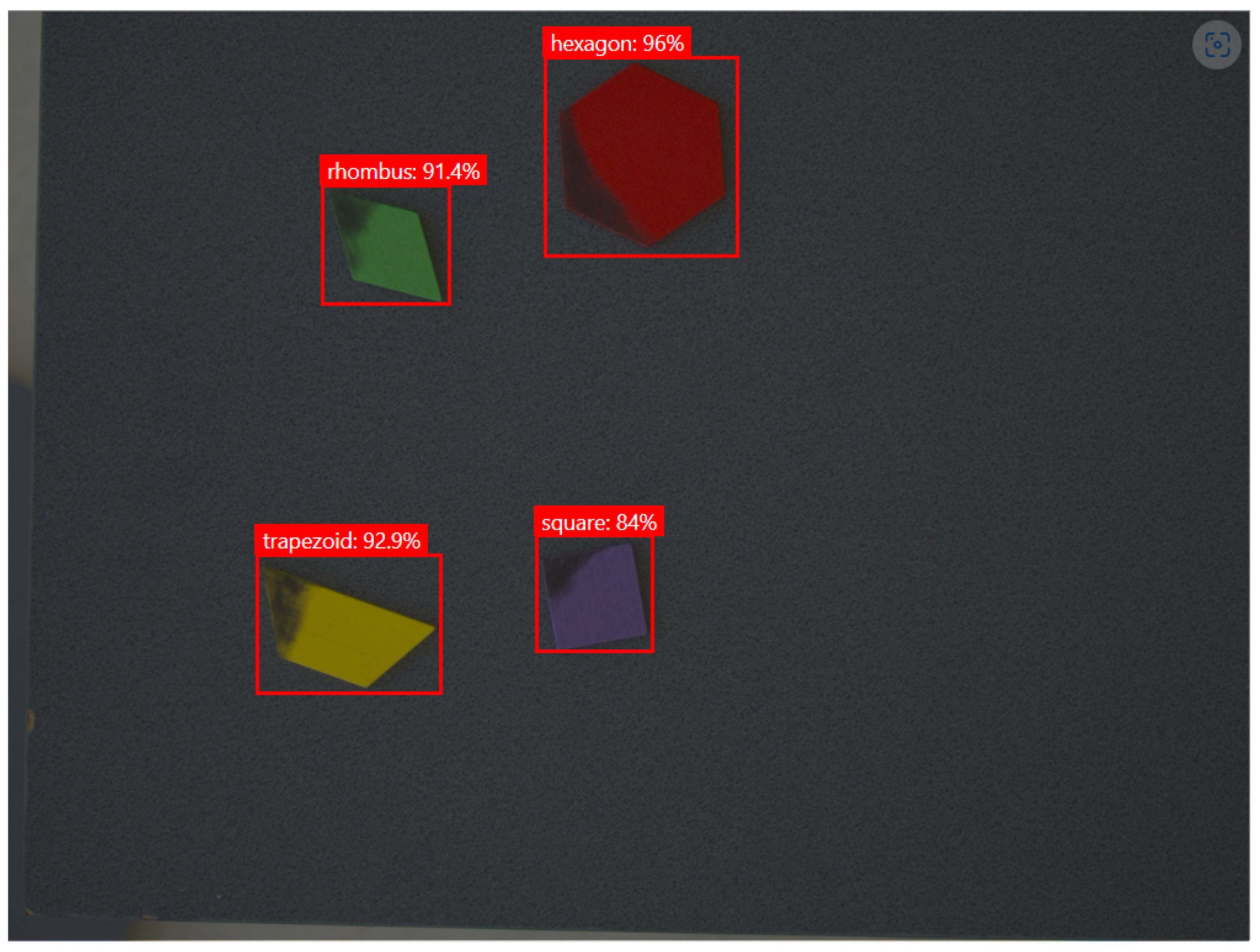
A screenshot of the bounding boxes and tags for the object that were identified using the industrial solution is presented in
Figure 8. The tool for identification is called “Deep Learning AI - Find Objects” and uses an NN computed by the MVTec Deep Learning Tool, trained in an analogous manner to the cloud solution, using the same 40 images of the objects, for which bounding boxes and tags were assigned.
In
Table 1 and
Table 2, ten experiments are presented for each system, five experiments conducted under natural light and five under artificial light, with one of each type of object. The detection confidence is displayed as provided by the vision system; the errors represent the position difference in millimeters in the vision plane from the placing point, as used by the industrial robot, and the pick point returned by the vision system. Finally, the time represents the duration of image processing in seconds or milliseconds, from the moment the image is sent to the vision system to the moment the results are received.
In
Table 3 and
Table 4 the mean values and SD are illustrated, in the same conditions as those previously obtained for each system. For this analysis, twelve experiments were performed for each object, placed in distinct positions and under both types of illumination, totaling 120 experiments.
In
Table 3, it can be observed that the lowest detection confidence, when using the cloud service, is obtained for the rhombus, under artificial light, with a mean of 0.63 and an SD of 0.13, while the best detection confidence is gained for the naturally illuminated circle, with a mean of 0.93 and an SD of 0.03. In terms of positioning error, the biggest error is seen when detecting the trapezoid, having a mean error on the X axis of 3.00 mm with an SD of 2.19 mm, and a mean error on the Y axis of 3.13 mm with an SD of 1.35 mm. The smallest errors can be seen in the detection of the circle, with errors of 0.53 mm on the X axis and 0.61 mm on the Y axis, along with SDs of 0.37 mm on the X axis and 0.53 mm on the Y axis.
A similar case can be seen in
Table 4, for the industrial application, with the smallest errors for the detection of the circle (0.66 mm mean error on the X axis and 0.4 mm SD and 0.48 mm mean error on the Y axis and 0.29 mm SD), and the biggest error for the trapezoid (3.05 mm mean and 1.69 mm SD on X axis, and 2.89 mm mean and 1.86 SD on Y axis). The confidence in this case varies extraordinarily little, with almost all cases having a confidence of 1, except for the square and trapezoid, which has reduced values when illuminated by artificial light.
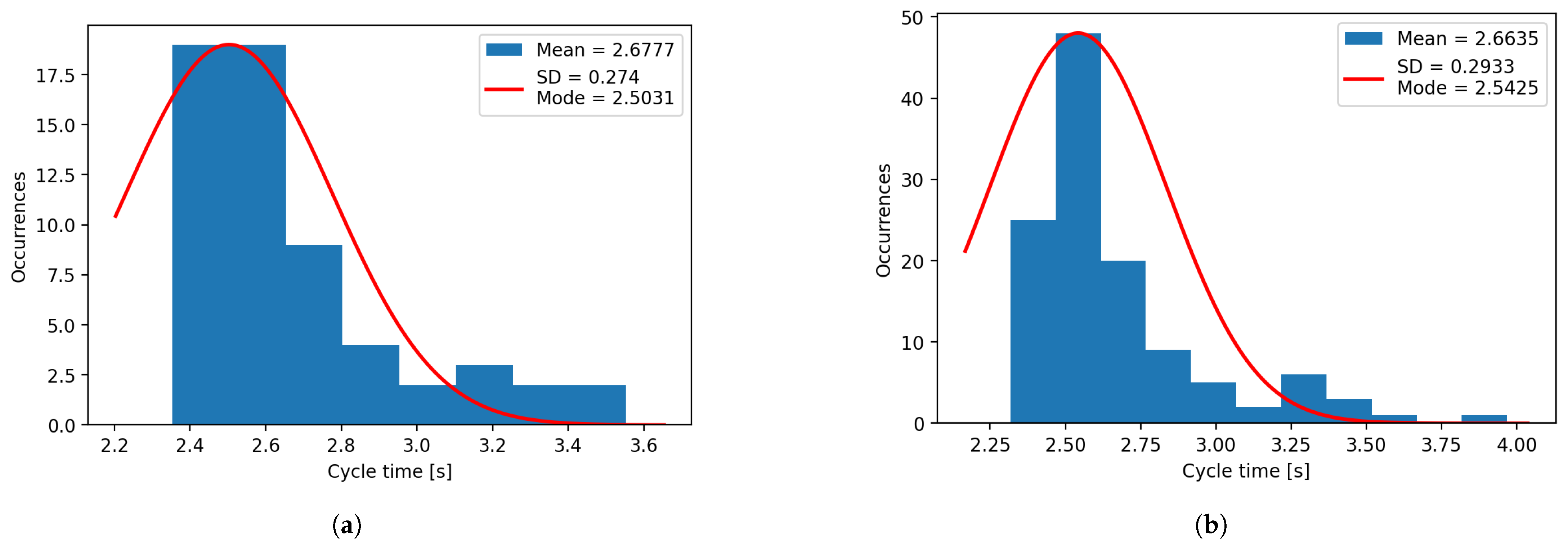
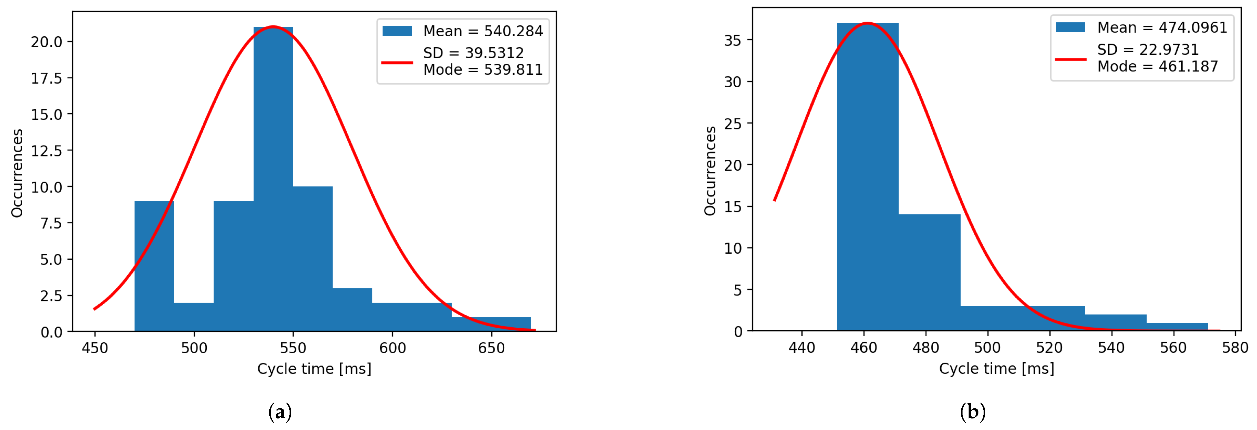
Regarding the response time, for both systems, the results are consistent and do not vary much with the object type or ambient light. In the case of the cloud system, the response time varies from a mean of 2.55 s and an SD of 0.14 s in the case of the artificially illuminated hexagon, to a mean of 2.94 s and an SD of 0.39 s for the naturally illuminated circle. The industrial software offers a response in about 500 ms in all cases, with the lowest average value being for the artificially lightened square (mean of 472.6 ms and SD of 27.7 ms) and the highest mean value for the naturally lightened trapezoid (mean of 564.6 ms and SD of 37.3 ms).
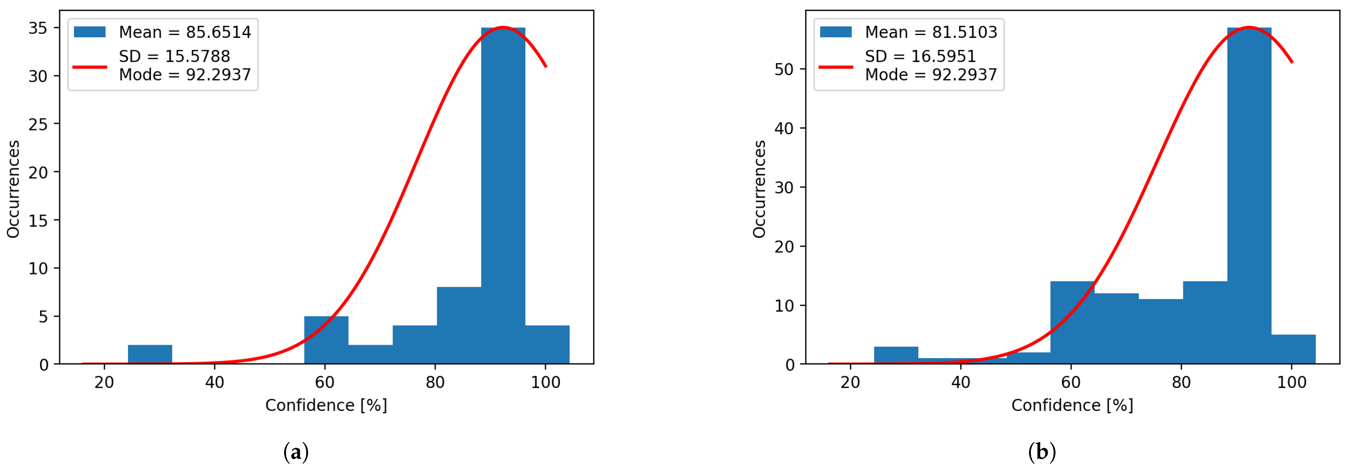
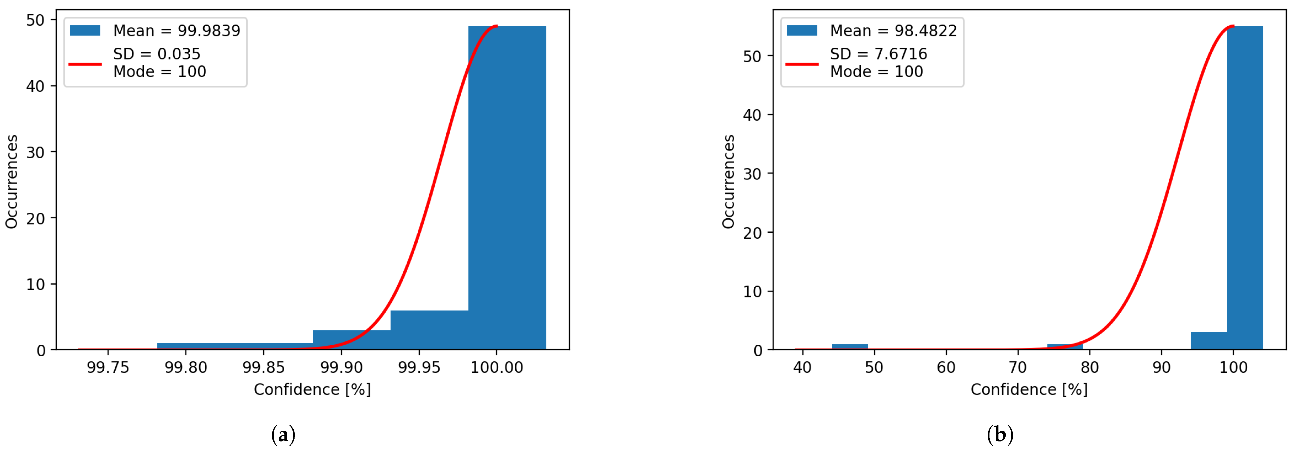
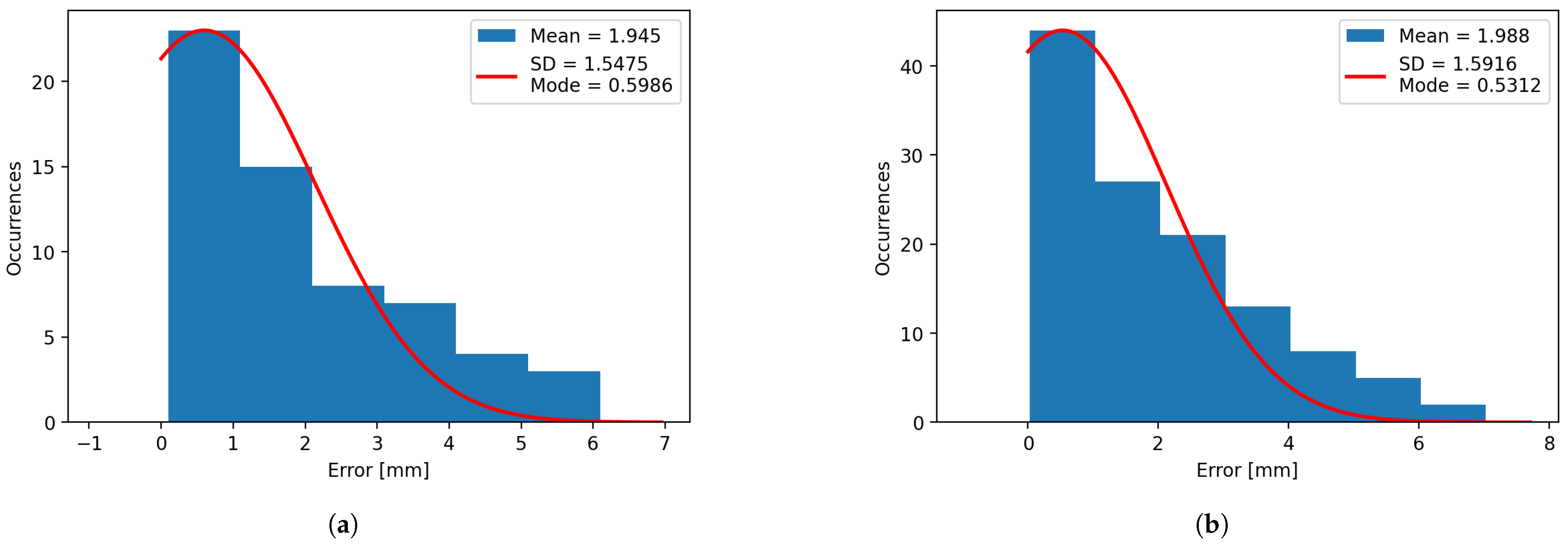
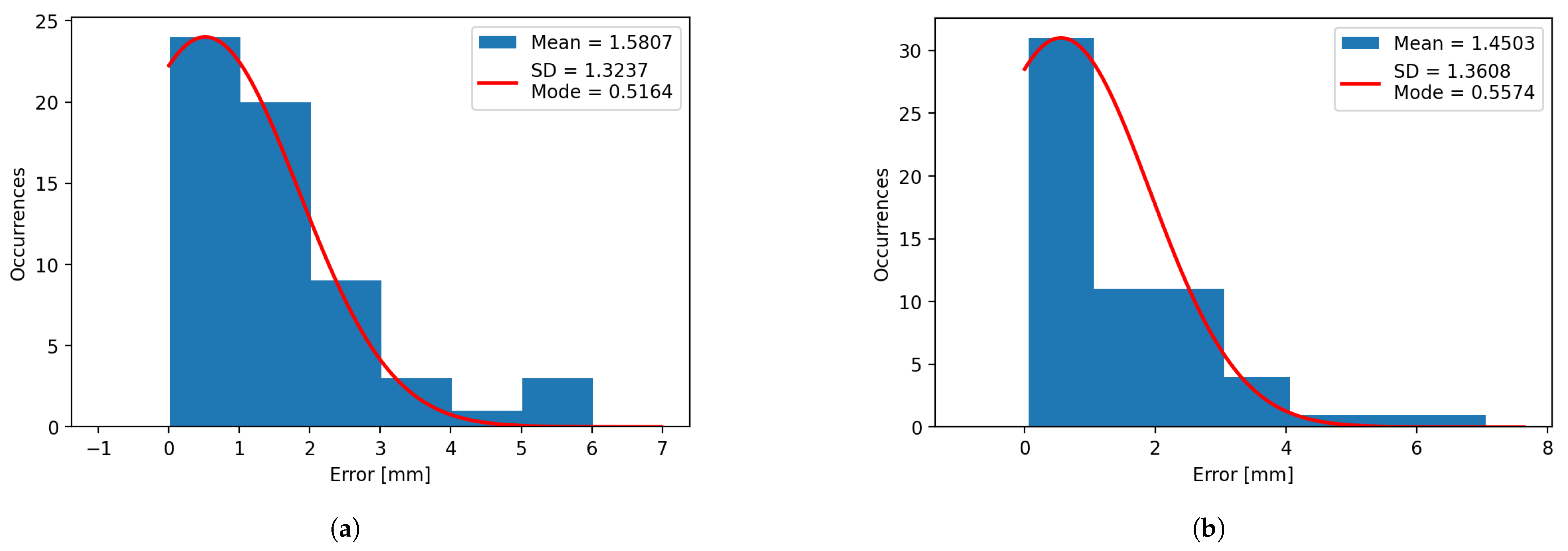
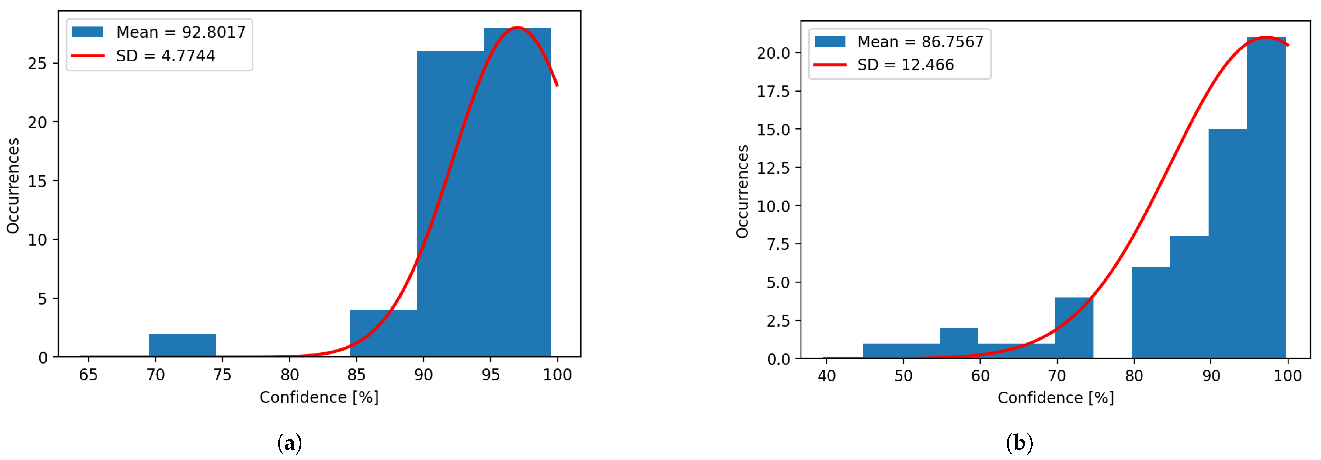
Using the data extracted from the same experiments, histograms for confidence (
Figure 9 and
Figure 10), error on ‘X’ axis (
Figure 11 and
Figure 12), error on ‘Y’ axis (
Figure 13 and
Figure 14) and time (
Figure 15 and
Figure 16) have been plotted for both systems. It can be observed that the mean and mode vary heavily for the plotted histograms, which denotes that the distributions are negatively skewed for the confidence, and positively skewed for the errors, due to their limits. The confidence cannot exceed 100%, and the error cannot be less than 0 mm.
5. Discussion
When using the real-world system, the images taken contain several added noises, such as the image background (the table) and the object’s texture, shadows, reflections, and change in coloration due to the different light sources used, as compared to our previous work, where the images are taken inside a simulated environment. These noises decrease the detection confidence and increase the positioning error in the real environments and may pose a problem when performing robot sorting operations.
The best results are obtained when using natural light, under which the model was trained, and for the circular object due to its symmetry, but the robot system successfully picks the object in every case.
Compared with the industrial software, the confidence in detection is reduced when using the cloud service, but the position errors remain similar. Regarding the response time, the local solution is faster, as to be expected, but the cloud response is not slow either.
The response time varies with Internet speed, but it remains consistent under the same test conditions. The network used has a receive and transmit speed of 433 Mbps, the size of the images varies from MB up to MB, and the resolution is .
In comparison with classical identification methods, which take into account the shape and contour of the object, the presented method can be used successfully for identification in cases when the objects are a bit dirty (
Figure 17) or they overlap (
Figure 18).
The results are better when using the industrial software, trained for the same images, but when using the detection images to improve the cloud solution model, the detection results are improved. In this case, we used the detection images with natural light to retrain and improve the model, obtaining the results presented in
Figure 19a for natural light, showing a 7.2% increase in detection confidence, and
Figure 19b for artificial light, with a respectable 5.2% increase. Aside from the increase in confidence, a reduction in the standard deviation of 10.8% for natural light and 4.1% for artificial light is present.
6. Conclusions
The cloud service obtained the best results in natural illumination conditions, with good prediction confidence and sufficiently few errors, ensuring object picking in every case. The implementation proved its overall connectivity consistency, while also demonstrating robustness, providing good results in the case of partially dirty objects.
The prediction confidence calculated by the Custom Vision and MVTec Merlic are not directly comparable since the methods of calculation of the confidence are not transparent for either of them. Per our observation, after making additional tests, the confidence of MVTec Merlic for cases of correct prediction tends to be closer to the extremes (either very high, which happens for most cases, or in specific cases, very low); we suspect that this behavior stems from the method used for calculating the confidence.
While the specialized software showed better and more consistent results overall, which is to be expected since it is a computer vision specifically made with industrial use in mind, the Custom Vision solution also performed satisfactorily. These results open additional application perspectives in the robotics field with quickly evolving AI technology and continuously increasing cloud capabilities.
It is worth mentioning that Custom Vision’s lower limit of images for the training to take place is 25, and the results compared were obtained for a trained model where we used 40 training images. We observed that for further training of the Custom Vision model with new images of the objects, its prediction confidence kept increasing. The point after which the confidence is not further increased by adding new images is yet to be determined.
Despite the revolutionary potential of cloud computing, this technology also comes with certain limitations on aspects such as security, flexibility, or performance caused by Internet dependency. Further research needs to be conducted on this topic to ensure the safety of data while optimizing performance, which could benefit not only individual end-users, but also enterprises that are using these types of services.
In the future, a system that combines classical object identification, based on contours and edges, with NN-based detection, based on the two systems that are compared in this work, can be developed to account for all the detection scenarios, in terms of light, background, overlap, and dust, to obtain the best overall results.
Author Contributions
Conceptualization, I.-L.S. and A.M.; methodology, I.-L.S., A.M. and S.R.; software, I.-L.S., A.M. and I.L.; validation, I.-L.S., A.M. and S.R.; formal analysis, I.-L.S. and A.M.; investigation, I.-L.S. and A.M.; resources, I.-L.S., F.D.A. and S.R.; data curation, A.M.; writing—original draft preparation, I.-L.S. and A.M.; writing—review and editing, I.-L.S., A.M., I.L., S.R., F.D.A., D.C.P. and I.S.S.; visualization, A.M.; supervision, S.R., D.C.P. and I.S.S.; project administration, A.M.; funding acquisition, F.D.A., I.-L.S. and A.M. All authors have read and agreed to the published version of the manuscript.
Funding
This work was supported by the National Program for Research of the National Association of Technical Universities GNaC ARUT 2023, grant number 83/11.10.2023 (optDDNc).
Data Availability Statement
Dataset available on request from the authors.
Conflicts of Interest
The authors declare no conflicts of interest.
Abbreviations
The following abbreviations are used in this manuscript:
| AI | Artificial Intelligence |
| API | Application Programming Interface |
| AWS | Amazon Web Services |
| CG | Correspondence Grouping |
| CNN | Convolutional Neural Networks |
| CPU | Central Processing Unit |
| ELU | Exponential Linear Unit |
| GPU | Graphics Processing Unit |
| IoRT | Internet of Robotic Things |
| JSON | JavaScript Object Notation |
| NN | Neural Network |
| ONNX | Open Neural Network Exchange |
| ReLU | Rectified Linear Unit |
| SD | Standard Deviation |
| SELU | Scaled Exponential Linear Unit |
References
- Dawarka, V.; Bekaroo, G. Building and evaluating cloud robotic systems: A systematic review. Robot. Comput.-Integr. Manuf. 2022, 73, 102240. [Google Scholar] [CrossRef]
- Zhang, H.; Zhang, L. Cloud Robotics Architecture: Trends and Challenges. In Proceedings of the 2019 IEEE International Conference on Service-Oriented System Engineering (SOSE), San Francisco, CA, USA, 4–9 April 2019; pp. 362–3625. [Google Scholar]
- Stefan, I.L.; Mateescu, A.; Vlasceanu, I.M.; Popescu, D.C.; Sacala, I.S. Utilizing Cloud Solutions for Object Recognition in the Context of Industrial Robotics Sorting Tasks. In Proceedings of the 2024 International Conference on INnovations in Intelligent SysTems and Applications (INISTA), Craiova, Romania, 4–6 September 2024; pp. 1–6. [Google Scholar]
- Fantozzi, I.C.; Santolamazza, A.; Loy, G.; Schiraldi, M.M. Digital Twins: Strategic Guide to Utilize Digital Twins to Improve Operational Efficiency in Industry 4.0. Future Internet 2025, 17, 41. [Google Scholar] [CrossRef]
- Roumeliotis, K.I.; Tselikas, N.D.; Nasiopoulos, D.K. Fake News Detection and Classification: A Comparative Study of Convolutional Neural Networks, Large Language Models, and Natural Language Processing Models. Future Internet 2025, 17, 28. [Google Scholar] [CrossRef]
- Sahnoun, S.; Mnif, M.; Ghoul, B.; Jemal, M.; Fakhfakh, A.; Kanoun, O. Hybrid Solution Through Systematic Electrical Impedance Tomography Data Reduction and CNN Compression for Efficient Hand Gesture Recognition on Resource-Constrained IoT Devices. Future Internet 2025, 17, 89. [Google Scholar] [CrossRef]
- Kamal, H.; Mashaly, M. Advanced Hybrid Transformer-CNN Deep Learning Model for Effective Intrusion Detection Systems with Class Imbalance Mitigation Using Resampling Techniques. Future Internet 2024, 16, 481. [Google Scholar] [CrossRef]
- Karri, C.; Naidu, M.S.R. Deep Learning Algorithms for Secure Robot Face Recognition in Cloud Environments. In Proceedings of the 2020 IEEE Intl Conf on Parallel & Distributed Processing with Applications, Big Data & Cloud Computing, Sustainable Computing & Communications, Social Computing & Networking (ISPA/BDCloud/SocialCom/SustainCom), Exeter, UK, 17–19 December 2020; pp. 1021–1028. [Google Scholar]
- Zhang, Y.; Li, L.; Nicho, J.; Ripperger, M.; Fumagalli, A.; Veeraraghavan, M. Gilbreth 2.0: An Industrial Cloud Robotics Pick-and-Sort Application. In Proceedings of the 2019 Third IEEE International Conference on Robotic Computing (IRC), Naples, Italy, 25–27 February 2019; pp. 38–45. [Google Scholar]
- Jiang, J. The eye of artificial intelligence—Convolutional Neural Networks. Appl. Comput. Eng. 2024, 76, 273–279. [Google Scholar] [CrossRef]
- Bryzgalov, P.; Maeda, T. Using Benchmarking and Regression Models for Predicting CNN Training Time on a GPU. In Proceedings of the PERMAVOST ’24: 4th Workshop on Performance EngineeRing, Modelling, Analysis, and VisualizatiOn STrategy, Pisa, Italy, 3–4 June 2024; pp. 8–15. [Google Scholar] [CrossRef]
- Li, X.; Li, R.; Zhao, Y.; Zhao, J. An improved model training method for residual convolutional neural networks in deep learning. Multimed. Tools Appl. 2021, 80, 6811–6821. [Google Scholar] [CrossRef]
- Trigka, M.; Dritsas, E. Edge and Cloud Computing in Smart Cities. Future Internet 2025, 17, 118. [Google Scholar] [CrossRef]
- Souza, D.; Iwashima, G.; Farias da Costa, V.C.; Barbosa, C.E.; de Souza, J.M.; Zimbrão, G. Architectural Trends in Collaborative Computing: Approaches in the Internet of Everything Era. Future Internet 2024, 16, 445. [Google Scholar] [CrossRef]
- Maenhaut, P.-J.; Moens, H.; Volckaert, B.; Ongenae, V.; De Turck, F. Resource Allocation in the Cloud: From Simulation to Experimental Validation. In Proceedings of the 2017 IEEE 10th International Conference on Cloud Computing (CLOUD), Honololu, HI, USA, 25–30 June 2017; pp. 701–704. [Google Scholar] [CrossRef]
- Saeed, H.A.; Al-Janabi, S.T.F.; Yassen, E.T.; Aldhaibani, O.A. Survey on Secure Scientific Workflow Scheduling in Cloud Environments. Future Internet 2025, 17, 51. [Google Scholar] [CrossRef]
- Jansi Sophia Mary, C.; Mahalakshmi, K.; Senthilkumar, B. Deep Dive On Various Security Challenges, Threats And Attacks Over The Cloud Security. In Proceedings of the 2023 9th International Conference on Advanced Computing and Communication Systems (ICACCS), Coimbatore, India, 17–18 March 2023; pp. 2089–2094. [Google Scholar] [CrossRef]
- Deepika; Kumar, R.; Dalip. Security Enabled Framework to Access Information in Cloud Environment. In Proceedings of the 2022 International Conference on Machine Learning, Big Data, Cloud and Parallel Computing (COM-IT-CON), Faridabad, India, 26–27 May 2022; pp. 578–582. [Google Scholar] [CrossRef]
- Atanasov, I.; Dimitrova, D.; Pencheva, E.; Trifonov, V. Railway Cloud Resource Management as a Service. Future Internet 2025, 17, 192. [Google Scholar] [CrossRef]
- Ji, P.; Chu, H.; Chi, J.; Jiang, J. A Resource Elastic Scheduling Algorithm of Service Platform for Cloud Robotics. In Proceedings of the 2020 Chinese Control and Decision Conference (CCDC), Hefei, China, 22–24 August 2020; pp. 4340–4344. [Google Scholar]
- Raheel, F.; Raheel, L.; Mehmood, H.; Kadri, M.B.; Khan, U.S. Internet of Robots: An Open-source Framework for Cloud-Based Global Remote Control and Monitoring of Robots. In Proceedings of the 2024 International Conference on Robotics and Automation in Industry (ICRAI), Rawalpindi, Pakistan, 18–19 December 2024; pp. 1–6. [Google Scholar]
- Chou, J.; Chung, W.-C. Cloud Computing and High Performance Computing (HPC) Advances for Next Generation Internet. Future Internet 2024, 16, 465. [Google Scholar] [CrossRef]
- Basler ace 2 Ra2A2590-22gcBAS. Available online: https://www.baslerweb.com/en/shop/a2a2590-22gcbas/ (accessed on 16 March 2025).
- Basler Lens C125-1620-5M f16mm. Available online: https://www.baslerweb.com/en/shop/lens-c125-1620-5m-f16mm/ (accessed on 16 March 2025).
Figure 1.
Training result of the model.
Figure 1.
Training result of the model.
Figure 2.
Cloud vision system architecture.
Figure 2.
Cloud vision system architecture.
Figure 3.
(a) The physical system and its components. (b) The transformation from the robot plane to the vision plane.
Figure 3.
(a) The physical system and its components. (b) The transformation from the robot plane to the vision plane.
Figure 4.
The event diagram.
Figure 4.
The event diagram.
Figure 5.
Transforming from camera coordinates to workobject coordinates.
Figure 5.
Transforming from camera coordinates to workobject coordinates.
Figure 6.
(a) Image taken of the hexagonal object under natural light. (b) Image taken of the hexagonal object under artificial light.
Figure 6.
(a) Image taken of the hexagonal object under natural light. (b) Image taken of the hexagonal object under artificial light.
Figure 7.
The picking point, calculated as the center of the bounding box.
Figure 7.
The picking point, calculated as the center of the bounding box.
Figure 8.
Detected objects, as seen in MVTec Merlic.
Figure 8.
Detected objects, as seen in MVTec Merlic.
Figure 9.
(a) Confidence histogram for natural light. (b) Confidence histogram for artificial light.
Figure 9.
(a) Confidence histogram for natural light. (b) Confidence histogram for artificial light.
Figure 10.
(a) Confidence histogram for natural light for the industrial software. (b) Confidence histogram for artificial light for the industrial software.
Figure 10.
(a) Confidence histogram for natural light for the industrial software. (b) Confidence histogram for artificial light for the industrial software.
Figure 11.
(a) Error histogram on the X axis for natural light. (b) Error histogram on the X axis for artificial light.
Figure 11.
(a) Error histogram on the X axis for natural light. (b) Error histogram on the X axis for artificial light.
Figure 12.
(a) Error histogram on the X axis for natural light for the industrial software. (b) Error histogram on the X axis for artificial light for the industrial software.
Figure 12.
(a) Error histogram on the X axis for natural light for the industrial software. (b) Error histogram on the X axis for artificial light for the industrial software.
Figure 13.
(a) Error histogram on the Y axis for natural light. (b) Error histogram on the Y axis for artificial light.
Figure 13.
(a) Error histogram on the Y axis for natural light. (b) Error histogram on the Y axis for artificial light.
Figure 14.
(a) Error histogram on Y axis for natural light, for the industrial software. (b) Error histogram on Y axis for artificial light, for the industrial software.
Figure 14.
(a) Error histogram on Y axis for natural light, for the industrial software. (b) Error histogram on Y axis for artificial light, for the industrial software.
Figure 15.
(a) Time histogram for natural light. (b) Time histogram for artificial light.
Figure 15.
(a) Time histogram for natural light. (b) Time histogram for artificial light.
Figure 16.
(a) Time histogram for natural light for the industrial software. (b) Time histogram for artificial light for the industrial software.
Figure 16.
(a) Time histogram for natural light for the industrial software. (b) Time histogram for artificial light for the industrial software.
Figure 17.
Detection results of dirty objects.
Figure 17.
Detection results of dirty objects.
Figure 18.
Detection results of overlapping objects.
Figure 18.
Detection results of overlapping objects.
Figure 19.
(a) Confidence histogram for natural light after retrain. (b) Confidence histogram for artificial light after retraining.
Figure 19.
(a) Confidence histogram for natural light after retrain. (b) Confidence histogram for artificial light after retraining.
Table 1.
Table presenting a part of the data obtained when using the cloud solution.
Table 1.
Table presenting a part of the data obtained when using the cloud solution.
| Experiment Number | Ambient Light | Object Type | Detection Confidence | X Error [mm] | Y Error [mm] | Time [s] |
|---|
| 1 | Natural | Circle | 0.95 | 0.13 | 1.80 | 3.50 |
| 2 | Natural | Square | 0.95 | 1.97 | 1.41 | 2.78 |
| 3 | Natural | Rhombus | 0.87 | 1.87 | 1.83 | 2.57 |
| 4 | Natural | Trapezoid | 0.96 | 0.10 | 2.90 | 2.57 |
| 5 | Natural | Hexagon | 0.82 | 0.17 | 0.30 | 2.45 |
| 6 | Artificial | Circle | 0.86 | 0.66 | 0.52 | 2.40 |
| 7 | Artificial | Square | 0.92 | 2.77 | 1.89 | 2.37 |
| 8 | Artificial | Rhombus | 0.78 | 0.65 | 0.81 | 2.87 |
| 9 | Artificial | Trapezoid | 0.79 | 0.63 | 3.45 | 2.45 |
| 10 | Artificial | Hexagon | 0.90 | 1.37 | 4.30 | 2.40 |
Table 2.
Table presenting a part of the data obtained when using the industrial solution.
Table 2.
Table presenting a part of the data obtained when using the industrial solution.
| Experiment Number | Ambient Light | Object Type | Detection Confidence | X Error [mm] | Y Error [mm] | Time [ms] |
|---|
| 1 | Natural | Circle | 0.99 | 2.15 | 1.04 | 481.3 |
| 2 | Natural | Square | 0.99 | 2.73 | 1.83 | 563.8 |
| 3 | Natural | Rhombus | 0.99 | 4.28 | 0.46 | 528 |
| 4 | Natural | Trapezoid | 0.99 | 3.29 | 1.51 | 533.6 |
| 5 | Natural | Hexagon | 1 | 4.07 | 1.30 | 520.2 |
| 6 | Artificial | Circle | 1 | 0.36 | 0.28 | 467.5 |
| 7 | Artificial | Square | 0.99 | 2.88 | 0.97 | 463 |
| 8 | Artificial | Rhombus | 0.99 | 3.23 | 1.14 | 474.6 |
| 9 | Artificial | Trapezoid | 0.99 | 5.60 | 0.51 | 459 |
| 10 | Artificial | Hexagon | 0.99 | 3.53 | 0.86 | 532.1 |
Table 3.
The mean and standard deviation for the confidence, error, and response time for all types of objects in different types of light for the cloud product.
Table 3.
The mean and standard deviation for the confidence, error, and response time for all types of objects in different types of light for the cloud product.
| Ambient Light | Object Type | Detection Confidence Mean/SD | X Error [mm] Mean/SD | Y Error [mm] Mean/SD | Time [s] Mean/SD |
|---|
| Natural | Circle | 0.93/0.03 | 1.04/0.62 | 1.71/0.92 | 2.94/0.39 |
| Natural | Square | 0.90/0.08 | 1.78/1.04 | 1.49/0.99 | 2.64/0.19 |
| Natural | Rhombus | 0.68/0.17 | 1.47/1.23 | 1.46/1.03 | 2.57/0.20 |
| Natural | Trapezoid | 0.85/0.20 | 2.9/1.79 | 1.84/1.04 | 2.57/0.14 |
| Natural | Hexagon | 0.89/0.05 | 2.50/1.85 | 2.05/1.41 | 2.64/0.15 |
| Artificial | Circle | 0.93/0.03 | 0.53/0.37 | 0.61/0.53 | 2.60/0.25 |
| Artificial | Square | 0.92/0.02 | 1.97/1.16 | 1.48/0.96 | 2.68/0.31 |
| Artificial | Rhombus | 0.63/0.13 | 2.06/1.00 | 1.46/0.91 | 2.65/0.26 |
| Artificial | Trapezoid | 0.66/0.11 | 3.00/2.19 | 3.13/1.35 | 2.75/0.44 |
| Artificial | Hexagon | 0.70/0.15 | 2.57/1.59 | 1.90/1.10 | 2.55/0.14 |
Table 4.
The mean and standard deviation for the confidence, error and response time for all types of objects in different types of light for the industrial software.
Table 4.
The mean and standard deviation for the confidence, error and response time for all types of objects in different types of light for the industrial software.
| Ambient Light | Object Type | Detection Confidence Mean/SD | X Error [mm] Mean/SD | Y Error [mm] Mean/SD | Time [ms] Mean/SD |
|---|
| Natural | Circle | 0.99/0 | 1.75/0.77 | 1.13/1.01 | 484.5/ 13.9 |
| Natural | Square | 0.99/0 | 2.52/0.85 | 1.26/0.94 | 548.6/30.6 |
| Natural | Rhombus | 0.99/0 | 2.6/1.43 | 1.08/0.75 | 549.8/20.9 |
| Natural | Trapezoid | 0.99/0 | 3.05/1.69 | 2.56/1.85 | 564.6/37.3 |
| Natural | Hexagon | 1/0 | 2.49/1.96 | 1.84/1.11 | 553.6/28.3 |
| Artificial | Circle | 1/0 | 0.66/0.40 | 0.48/0.29 | 473.5/20 |
| Artificial | Square | 0.95/0.15 | 2.76/1.2 | 1.29/0.87 | 472.6/27.7 |
| Artificial | Rhombus | 0.99/0.01 | 2.47/1.07 | 1.1/1.02 | 467.4/18.4 |
| Artificial | Trapezoid | 0.97/0.06 | 2.89/2.48 | 2.89/1.86 | 473.9/22.4 |
| Artificial | Hexagon | 1/0 | 2.79/1.57 | 1.46/0.84 | 482.8/22.3 |
| Disclaimer/Publisher’s Note: The statements, opinions and data contained in all publications are solely those of the individual author(s) and contributor(s) and not of MDPI and/or the editor(s). MDPI and/or the editor(s) disclaim responsibility for any injury to people or property resulting from any ideas, methods, instructions or products referred to in the content. |
© 2025 by the authors. Licensee MDPI, Basel, Switzerland. This article is an open access article distributed under the terms and conditions of the Creative Commons Attribution (CC BY) license (https://creativecommons.org/licenses/by/4.0/).
