Article

Hybrid Sensor Fusion Beamforming for UAV mmWave Communication

Department of Electronic Engineering, Institute of Science Tokyo, Tokyo 152-8550, Japan
*
Authors to whom correspondence should be addressed.
Future Internet 2025, 17(11), 521; https://doi.org/10.3390/fi17110521
Submission received: 15 October 2025 / Revised: 10 November 2025 / Accepted: 13 November 2025 / Published: 17 November 2025

Abstract

Resilient autonomous inter-Unmanned Aerial Vehicle (UAV) communication is critical for applications like drone swarms. While conventional Global Navigation Satellite System (GNSS)-based beamforming is effective at long ranges, it suffers from significant pointing errors at close range due to latency, low update rates and the inherent GNSS positioning error. To overcome these limitations, this paper proposes a novel hybrid beamforming system that enhances resilience by adaptively switching between two methods. For short-range operations, our system leverages Light Detection and Ranging (LiDAR)–camera sensor fusion for high-accuracy, low-latency UAV tracking, enabling precise millimeter-wave (mmWave) beamforming. For long-range scenarios beyond the camera’s detection limit, it intelligently switches to a GNSS-based method. The switching threshold is determined by considering both the sensor’s effective range and the pointing errors caused by GNSS latency and a UAV velocity. Simulations conducted in a realistic urban model demonstrate that our hybrid approach compensates for the weaknesses of each individual method. It maintains a stable, high-throughput link across a wide range of distances, achieving superior performance and resilience compared to systems relying on a single tracking method. This paves the way for advanced autonomous drone network operations in dynamic environments.

1. Introduction

1.1. Background

Unmanned Aerial Vehicles (UAVs), or drones, are rapidly becoming integral to various applications such as logistics, inspection, and public safety. For instance, they can establish network areas by performing relay communications between UAVs during disasters or large-scale events when network capacity is strained. The concept of drone swarms, where multiple UAVs operate collaboratively, is expected to revolutionize these fields by enabling complex tasks beyond the capabilities of a single drone. A fundamental prerequisite for effective swarm operation is a reliable, high-bandwidth, and autonomous communication link between the UAVs. However, establishing such links, particularly in dynamic and cluttered urban environments, remains a significant challenge.
To support such high-capacity communication, the use of millimeter-wave (mmWave) bands, which offer wide bandwidth, is required [1,2]. However, mmWave signals suffer from high attenuation and strong directionality, making directional beamforming essential. This technology necessitates precise and continuous alignment between the transmitter and receiver, a task made difficult by the high mobility of UAVs.
Inter-UAV communication is an essential foundational technology for advanced missions. These include deploying UAVs to provide wireless networking and communication services in specific geographic areas [3], extending the coverage and enhancing the reliability of existing wireless networks [4], or conducting post-disaster surveillance [5]. The requirement for high-precision beam tracking in these applications poses a significant challenge for autonomous UAV systems. Unlike conventional terrestrial links, UAV communication links are exposed to two key vulnerabilities. The first is Dynamic Topology and Instability. As UAVs move and maneuver rapidly in 3D space, link connectivity changes dynamically. Furthermore, wind gusts can induce high-speed jitter in the airframe, which continuously disrupts beam pointing. The second vulnerability is the Lack of Reliable Positioning. Conventional beam steering relies heavily on absolute coordinates from GNSS. However, in complex environments such as the urban or disaster scenarios we target, GNSS reliability is severely compromised by signal blockage (NLOS) and multipath from buildings and bridges, or by intentional interference. Therefore, we define “Resilient Inter-UAV Communication” as a robust and reliable system that autonomously leverages alternative sensing (e.g., Camera/LiDAR) to maintain and sustain high-gain beam directivity, even under harsh conditions such as in GNSS-denied environments or in the presence of wind-induced jitter.

1.2. Related Research

Conventional beamforming methods for UAVs typically rely on channel state information, such as pilot-based codebooks [6,7], or on position data from GNSS [8]. However, these approaches have limitations, such as the need for feedback from the receiver and being restricted to predefined, discrete angles in the codebook method, and significant multipath errors in urban environments for the GNSS method. In environments such as forests and urban areas, GNSS suffers from severe attenuation, interference, and multipath effects, significantly degrading UAV positioning performance [9]. To mitigate this degradation when coordinating multiple drones, some algorithms incorporate interference avoidance [10]. Jamming occurs due to interference, and since GNSS inherently requires information from satellites, it is susceptible to surrounding influences. Consequently, research to compensate for GNSS uncertainty is frequently conducted. Some GNSS systems, such as Real Time Kinematic-Global Positioning System (RTK-GPS), can achieve centimeter-level positioning accuracy by utilizing reference stations, but their installation incurs significant costs. Research employing sensor fusion with IMUs typically configures reference stations as base stations [11]. However, in the dynamic environment envisioned for UAV-to-UAV communication in this paper, there is no fixed infrastructure like base stations. Furthermore, the use case involves potential movement to locations without ground infrastructure, making the use of reference stations impractical.
More recent work has explored onboard sensors like cameras [12] or deep learning models like LSTM to predict beam directions [13]. In mmWave communication systems, maintaining stable and efficient communication links for UAVs remains a challenge due to beam misalignment caused by UAV movement. Against this backdrop, research is also being conducted on changing the beam itself—adjusting its width to adapt to dynamic environments [14]. Although network design based on variations in the half-power beamwidth has already been investigated [2,15], analysis from the perspective of beam-switching methods remains a subject for future work. While promising, these studies are often limited to different scenarios such as UAV-to-vehicle communication or base station-to-UAV links, and they often neglect the critical initial link acquisition and recovery phases. Other research also adopts an approach of using base station-mounted cameras and deep learning to “predict” the optimal beam index for vehicles [16]. This novel deep learning method, which incorporates image-based coding (IBC), treats the millimeter-wave beam search as an image processing problem based on situational awareness. Although this method demonstrates high robustness for high-speed vehicles, it is limited to base station-to-vehicle (V2I) communication. Our research differs from this, as our focus is not on prediction, but rather on a hybrid strategy that compensates for the respective weaknesses of two sensing modalities with different characteristics. Although various LiDAR-based detection methods exist [17,18], their applicability to small, mobile UAVs remains unclear. Thus, it is impossible to realize a perfect system using only a single sensor, such as GNSS, as each has inevitable disadvantages in various aspects.
Multi-sensor fusion approaches using both camera and LiDAR also exist, such as the frustum-based method in [19] used to detect cars and pedestrians. Motivated by its potential to improve accuracy over LiDAR-only methods and its applicability to UAVs, we extend this technique for our beamforming application.
Our prior work [20] successfully estimated propagation loss based on detection and environmental data, but it did not validate a practical beam steering implementation or its effectiveness considering realistic latency. As another prior work [21], we propose a novel framework that leverages onboard perception sensors—specifically LiDAR and a camera—to directly detect a peer UAV in low-latency and perform beamforming. The resulting position information is used to dynamically control a phased array antenna, steering a narrow millimeter-wave beam to establish and maintain a robust communication link. Though this proposed method shows high quality link communication, the coverage was limited due to the camera-based beam steering mechanism. Therefore, this paper proposes a more resilient UAV beamforming system which enables a wider communication range.
The main contributions of this paper are threefold: (1) the development of a Camera/LiDAR detection and tracking system and Hybrid method which combine Camera/LiDAR and GNSS; (2) the implementation of low-latency, autonomous beam steering driven by sensor data; and (3) the validation of the proposed system through high-fidelity simulations in a realistic urban model. Recent trends include drone swarm coordination [22] and passing communication. The need for close-range communication between drones is increasing, making current GNSS alone prone to significant errors. To expand the communication area, we are exploring a hybrid model combining GNSS with Camera/LiDAR. This hybrid approach allows each sensor to cover areas where the other’s disadvantages cause communication quality to deteriorate significantly.
Cooperative optimization in complex systems requires the application of cutting-edge AI technologies such as Deep Reinforcement Learning (DRL). Research has demonstrated optimization to maximize energy efficiency (EE) within the complex intelligent reflecting surfaces (IRS)-integrated sensing and communication (ISAC) system [23,24]. Cooperative resource management challenges in such dynamic systems remain a key future research topic.
The integration of environmental awareness technologies, such as the predictive 3D Radio Environment Maps (REM) that model shadowing, is considered the ideal next step to further advance this hybrid approach [25]. Constructing a spatial reliability map and incorporating it into the switching decision would dramatically improve the system’s resilience.

2. Materials and Methods

2.1. System Pipeline Overview

Our proposed methodology is divided into two main parts, as illustrated in Figure 1. The first is the overall framework, which is a hybrid approach that switches the beamforming system based on the distance to the target. One of the two candidate systems for this switching, the Camera/LiDAR method, is itself a novel method that we propose based on sensor fusion. Therefore, the pipeline for the Camera/LiDAR method is integrated as a component within the overall pipeline of the hybrid system. The system comprises a sequence of processes designed for an ego UAV to acquire and maintain a communication link with a target UAV. The Camera/LiDAR pipeline consists of three primary stages:
  • 2D Vision-based Detection: In the initial stage, the onboard camera of the ego UAV detects the target UAV within the image plane using a computer vision algorithm. This provides the general direction of the target, but at this point, it yields only a 2D bounding box, lacking essential depth information.
  • 3D Localization via Sensor Fusion: Next, the system fuses the 2D detection results from Stage 1 with the 3D point cloud data obtained from the onboard LiDAR. This sensor fusion process enables the precise localization of the target UAV, yielding its 3D relative coordinates (x, y, z).
  • Beamforming Control: In the final stage, based on the 3D relative coordinates calculated in Stage 2, the system electronically steers a phased array antenna to direct the main lobe of the millimeter-wave beam toward the target UAV, maximizing the received signal strength.
By iterating through this pipeline at a high frequency, the system continuously tracks the moving target UAV to maintain a stable communication link.

2.2. Perception Module: Sensor-Based UAV Detection

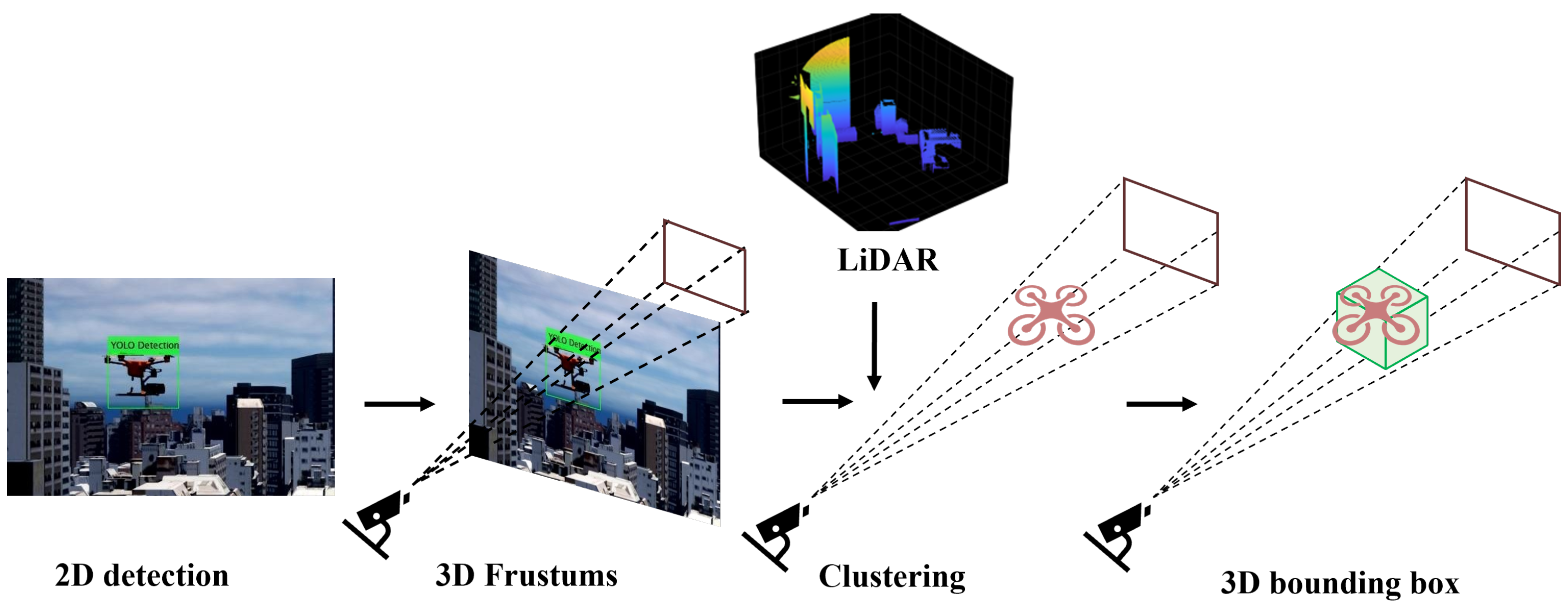
The perception module, which fuses data from LiDAR and a camera, serves as the “eyes” of our system. Its objective is to accurately localize the target UAV’s 3D relative position within the ego UAV’s sensor coordinate frame. This section details the methodology for achieving this (Figure 2).
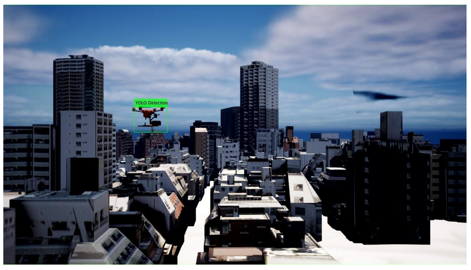
We employ a YOLO-based (You Only Look Once) model [26] for real-time 2D object detection due to its high speed, which is essential for tracking a fast-moving UAV (Figure 3). However, the resulting 2D bounding box ( B 2 D ) lacks depth information. Therefore, to determine the 3D position, we use a frustum-based sensor fusion method.
In this approach, the 2D bounding box is first projected into 3D space to form a viewing frustum, drastically narrowing the search space within the LiDAR point cloud. A clustering algorithm is then applied exclusively to the points within this frustum to identify the target UAV, and a 3D bounding box ( B 3 D ) is fitted to this cluster. The centroid of this B 3 D provides the final 3D relative position of the target.
A critical prerequisite for this fusion method is a precise Extrinsic Calibration to align the disparate coordinate systems of the camera and the LiDAR. The goal of this calibration is to determine the rigid body transformation—comprising a Rotation Matrix (R) and a Translation Vector (T)—that maps coordinates from one sensor frame to the other. This transformation matrix allows for the accurate projection of 3D points onto the 2D image plane, enabling the frustum-based fusion described above.
The primary goal of LiDAR–camera calibration is to find the rigid body transformation that maps points from the LiDAR coordinate system to the camera coordinate system. This transformation is defined by the extrinsic parameters: a 3 × 3 rotation matrix R and a 3 × 1 translation vector T . A 3D point P L in the LiDAR frame is transformed into the camera’s 3D coordinate frame P C using the following equation:
P C = R · P L + T
This 3D point P C is then projected onto the 2D image plane at pixel coordinates [ u , v ] T using the pinhole camera model. This projection is governed by the camera’s intrinsic parameter matrix, K :
s u v 1 = K · P C = K ( R · P L + T )
where s is a scalar depth value and K is the camera intrinsic matrix. In this work, the extrinsic parameters R and T were estimated using the MATLAB (ver. 24.1.0.2837808 (R2024a)) Lidar Camera Calibrator (The MathWorks, Inc., Natick, MA, USA). This tool optimizes these parameters by minimizing the reprojection error between the 3D points from the LiDAR point cloud and their corresponding 2D feature points (e.g., checkerboard corners) detected in the camera image.

2.3. Beam Control Module

The 3D relative position of the target UAV, as determined by the perception module (Section 2.2), is fed into the beam control module. The role of this module is to translate this position vector into a concrete physical command to drive the phased array antenna.
First, we define the input as the 3D relative position vector of the target UAV, p = ( x , y , z ) , which corresponds to the centroid of the 3D bounding box described in the previous section. This Cartesian coordinate vector must be converted into spherical coordinates—specifically, azimuth ( θ ) and elevation ( ϕ )—to command the antenna. The angles are calculated as follows:
θ = arctan 2 ( y , x )
ϕ = arctan z x 2 + y 2
where ( x , y , z ) are the coordinates in the antenna’s local frame, with the x-axis typically pointing forward and the z-axis pointing upward.
The calculated angles ( θ , ϕ ) represent the desired beam direction. A phased array antenna operates by individually controlling the phase of the signals emitted from its multiple antenna elements, causing constructive interference in a specific direction. The specific set of complex weights (amplitude and phase) for this phase control is known as the steering vector. By generating a steering vector from the calculated target angles ( θ , ϕ ) and applying it to the antenna elements, the beam is electronically and accurately steered toward the target UAV. The simulation framework is built upon the fundamental principles of phased array antenna theory. The theoretical performance of the beamforming system is primarily determined by the array gain, the array factor, which defines the beam pattern, and the steering vector, which controls the beam direction. The theoretical maximum gain of a Uniform Rectangular Array (URA) is proportional to the number of antenna elements, N. This relationship, known as the array gain, is expressed in decibels as
G array [ dBi ] 10 log 10 ( N ) + G element [ dBi ]
where N is the total number of elements (e.g., N = 256 for a 16 × 16 array) and G element is the gain of a single element (approx. 3 dBi in our model). This equation provides the theoretical basis for evaluating different antenna configurations (e.g., 8 × 8, 16 × 16, 32 × 32), as a larger N yields a higher gain, which in turn necessitates narrower beams. The core of beamforming lies in applying a precise phase shift to each element to ensure constructive interference in a desired direction. For a URA in the y-z plane (ArrayNormal = ‘x’), the required phase shift Ψ m , n for the element at row n and column m to steer the beam to an azimuth angle θ and elevation angle ϕ is given by the steering vector calculation:
Ψ m , n ( θ , ϕ ) = 2 π d λ ( m cos ϕ sin θ + n sin ϕ )
where d is the element spacing (set to λ / 2 ) and λ is the wavelength.The complete antenna radiation pattern, or Array Factor (AF), is then calculated by the inner product of the applied complex weights ( w ) and the steering vector ( a ( θ , ϕ ) ) for that direction:
A F ( θ , ϕ ) = w H a ( θ , ϕ )
In our simulation, the weight vector w applied to the antenna is derived from the steering vector corresponding to the target direction (e.g., w = a * ( θ target , ϕ target ) for conventional beamforming). This theoretical framework is used to calculate the antenna’s half-power beamwidth (HPBW) and the resulting pointing loss.

2.4. Baseline Method for Comparison

To evaluate the effectiveness of our proposed method, we establish two representative baseline methods for comparison.

2.4.1. Pilot-Based Beam Sweeping

This method uses a predefined codebook of beam directions and relies on receiver feedback from pilot signals to find the optimal beam. While efficient for tracking via local search, it incurs substantial latency during initial acquisition or link recovery due to the need for an exhaustive search.

2.4.2. GNSS-Based Beam Steering

This method directly calculates the beam direction using absolute position data from GNSS, avoiding an exhaustive search. However, it is unreliable for narrow beams as it suffers from significant positioning errors, which are exacerbated by multipath effects in urban environments. Furthermore, as a problem specific to UAVs, their high speed of movement causes significant errors to accumulate between GNSS update intervals, particularly at close range.
These two baseline methods, with their respective challenges of “latency” and “positioning error,” as well as the shared constraint that both require feedback from the target, serve as ideal benchmarks against which to demonstrate how our perception-based approach solves these critical issues.

2.5. Hybrid Approach

Our primary proposed method is an autonomous, low-latency, and high-accuracy detection and beamforming system based on a camera and LiDAR. However, a drawback of this method is its reliance on camera detection, which can fail if the camera’s resolution is insufficient or if the target UAV is too distant. Our previous work [21] was limited to short-range simulations within the camera’s effective detection range. As a further enhancement, we propose a hybrid approach that compensates for the limited range of the camera by utilizing GNSS for long-range scenarios. As previously discussed, at close range, the low update rate of GNSS can cause significant tracking errors for high-velocity objects like UAVs. This often results in a pointing error that exceeds the half-power beamwidth (HPBW) of a narrow, high-gain beam. Conversely, our proposed Camera/LiDAR method provides superior detection accuracy at close range. At long ranges, the proposed method reaches its detection limit. For the GNSS-based method, however, the angular error resulting from a fixed linear positioning error decreases with distance, making it more likely to fall within the beam’s HPBW and thus yielding better beamforming performance.
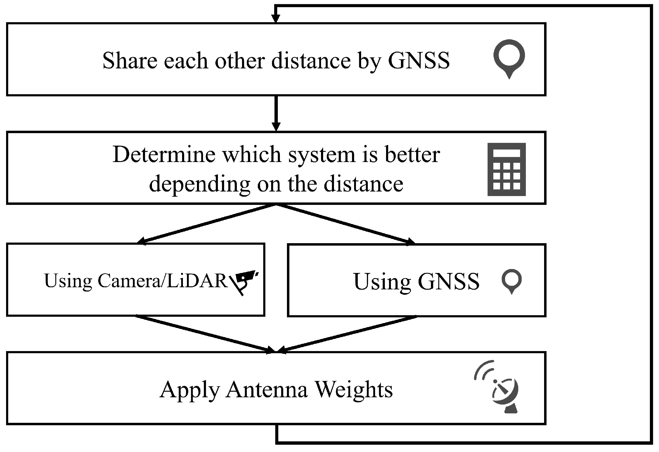
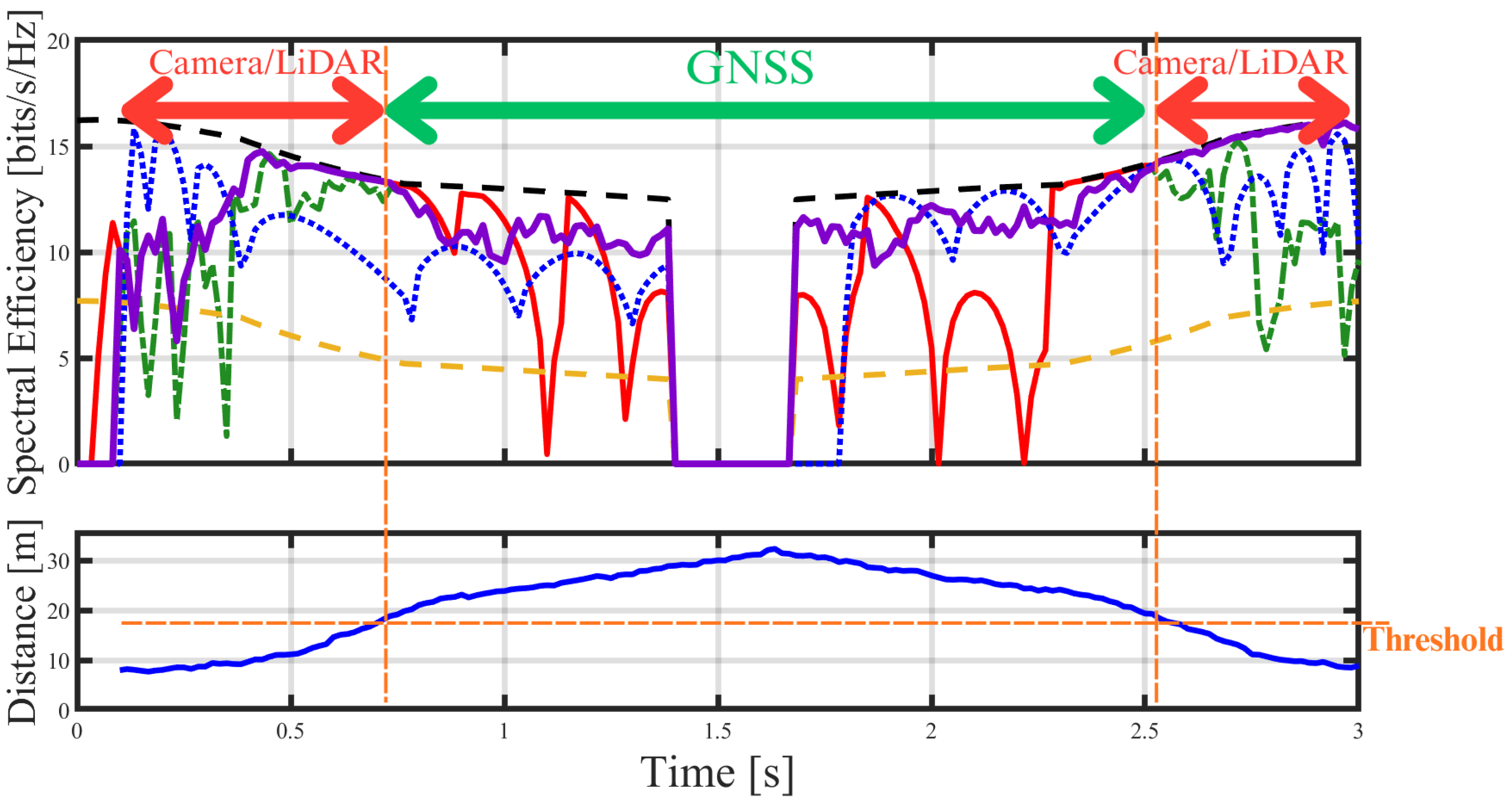
Figure 4 shows a diagram of our proposed hybrid approach. Initially, the two UAVs determine their relative distance via GNSS. Although GNSS positioning is subject to significant errors as previously discussed [27], this is not a critical issue for this particular task, as the distance measurement is used solely for thresholding. When the inter-UAV distance is greater than a predefined threshold, the system employs the GNSS-based method, as the resulting angular error is small enough to fall within the antenna’s half-power beamwidth (HPBW). However, once the distance drops below the threshold, the angular error from GNSS becomes too large for effective tracking with a narrow beam. At this point, the system switches to the high-accuracy Camera/LiDAR method. The position of the target UAV, acquired by the selected method, is then used to calculate and apply the appropriate weights to the antenna for beamforming. Of course, the optimal value for this switching threshold could be considered dynamic, as the HPBW changes depending on the antenna gain. However, the threshold must also be considered from the perspective of the camera’s physical detection limits. In such a case, it is also conceivable to set the threshold at a fixed distance based on the camera’s maximum effective range, regardless of the antenna gain. The prevalent handover method is reactive, initiating only when trigger conditions are met during the Time-to-Trigger (TTT) period [28]. To improve Quality of Service (QoS) during handover, proactive handover methods utilizing past observation data via machine learning have been proposed [29]. SNR-based handover is reactive, switching may occur only after SNR has actually degraded, potentially being too late. Furthermore, since SNR degradation can stem from factors like directional errors or interference, basing decisions on distance—the root cause—enables more robust judgment.
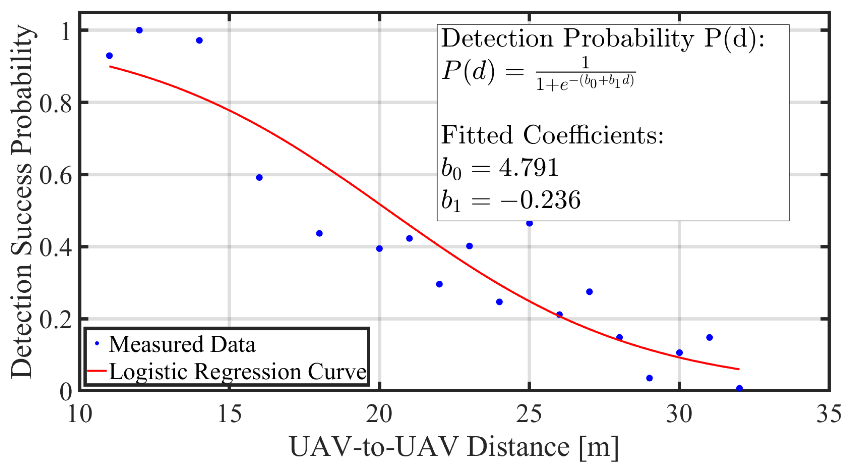
To determine this threshold, we investigated the relationship between distance and detection accuracy in our simulation environment. Figure 5 shows the results. The experiment was conducted in a scenario where the receiver UAV flies along a circular arc at a constant distance from a hovering transmitter UAV, within the camera’s field of view. The results show that as the distance increases, the target appears smaller, leading to a decrease in detection accuracy. We fit a sigmoid function to this empirical data and use this function to inform the threshold calculation. By comparing the Camera/LiDAR method, which incorporates this decay model, with the GNSS method, which is heavily affected by positioning errors, we set the threshold as the crossover distance where their respective communication qualities intersect.
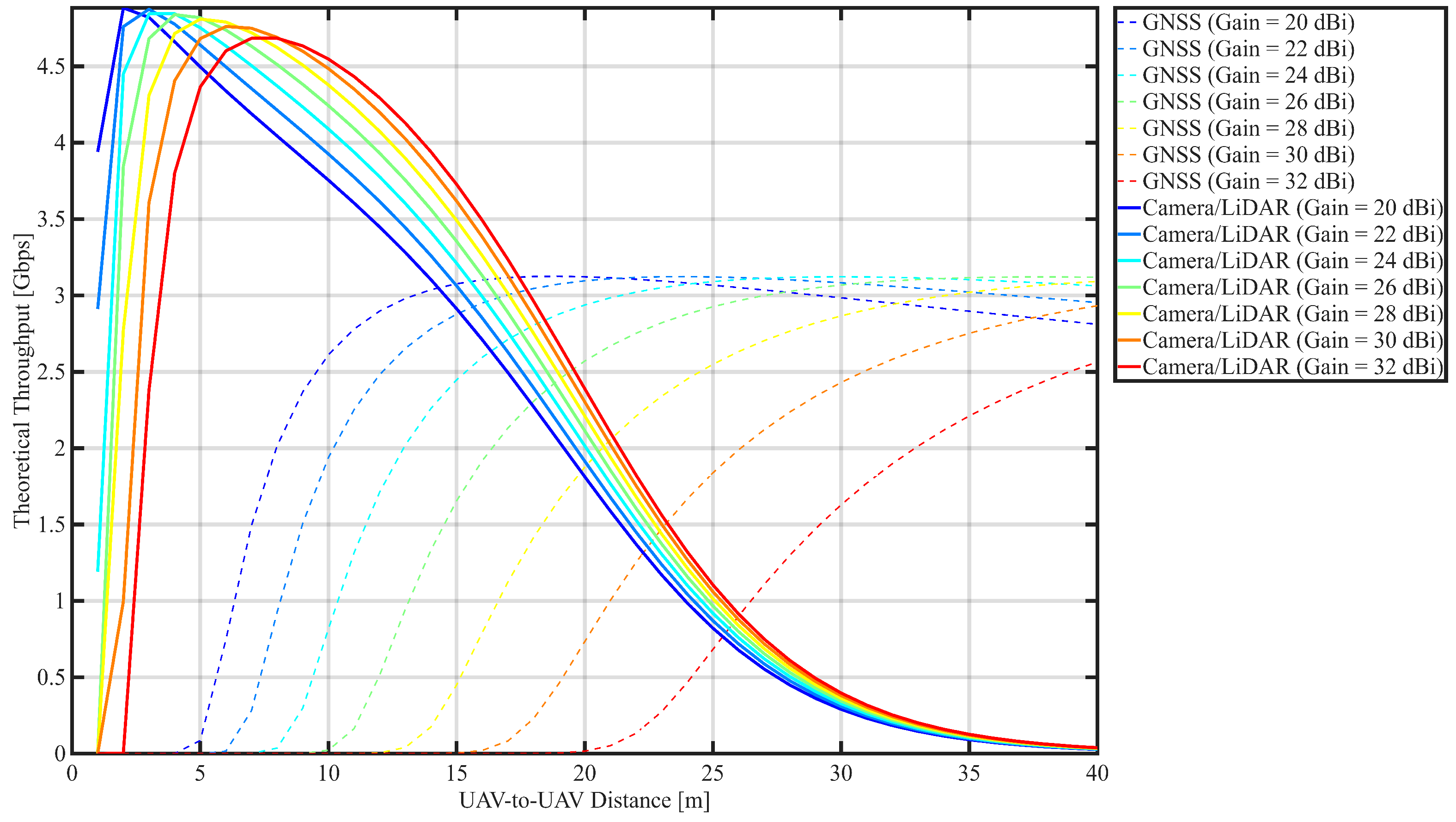
To validate this hybrid approach, we simulated the throughput as a function of distance for various antenna gains. Figure 6 shows the results of the numerical simulation performed in MATLAB. After defining the communication parameters, the impact of positioning errors was modeled by calculating the pointing loss. Specifically, for each distance, we calculate the corresponding angular error from a given linear error and then model the power loss that occurs when the beam deviates by that angle. The simulations were conducted for a range of candidate antenna gains, from 20 dBi (corresponding to an 8 × 8 array) up to 32 dBi (corresponding to a 32 × 32 array of approximately 4 cm × 4 cm, a physically mountable size for a UAV), in 2 dBi increments.
The simulation evaluates the theoretical throughput between two UAVs as a function of distance, considering the impact of positioning errors from different sensors. We assume a millimeter-wave communication system operating at a carrier frequency of 60 GHz with a channel bandwidth of 300 MHz. The transmitter UAV is equipped with a steerable phased array antenna, and its transmit power is set to 20 dBm. The receiver UAV is assumed to have an isotropic antenna with a gain of 0 dBi. The simulation sweeps the transmitter’s antenna gain from 20 dBi to 32 dBi in 2 dBi increments. The half-power beamwidth (HPBW) of the antenna is modeled as a function of its gain, based on a reference 16 × 16 array (Gain = 25.9 dBi, HPBW = 6.36°), using the following approximation:
HPBW deg = 6.36 · 10 G dBi 25.9 20
where G dBi is the antenna gain in dBi. The theoretical throughput C is calculated based on the Shannon–Hartley theorem:
C = B · log 2 ( 1 + SNR )
The Signal-to-Noise Ratio (SNR) is determined by the link budget, which incorporates free-space path loss (FSPL) and a critical pointing loss term caused by positioning errors. The received power P R x (in dBm) is given by
P R x = P T x + G T x + G R x L path L pointing
The impact of positioning error on performance is modeled by calculating the resulting pointing loss. First, the angular error, θ err , is derived from the linear positioning error, ϵ linear , and the inter-UAV distance, d. This relationship is based on the following trigonometric formula:
θ err = arctan ϵ linear d
Subsequently, this angular deviation causes a pointing loss, L pointing (in dB). By approximating the antenna’s main lobe with a Gaussian function, this loss is modeled as a function of the angular error and the antenna’s half-power beamwidth (HPBW):
L pointing 12 θ err HPBW 2
To compare the performance of the GNSS-based method and our proposed Camera/LiDAR method, two distinct error models were used. For the GNSS method, the linear positioning error, ϵ linear , was assumed to be a constant offset of 2.5 m. The total GNSS error is defined by summing two components: the hovering accuracy of the real airframe [30] and an error term from the update latency, which is calculated by multiplying the update interval by the UAV’s velocity. Assuming an average UAV velocity of 20 m/s, a positioning error of 2 m is generated from the system latency, even with a high-precision GNSS update rate of 10 Hz. In contrast, for the proposed Camera/LiDAR method, the linear positioning error was set to 0.3 m. This value is based on our real-world simulations, where errors in detection, such as detecting the edge of the UAV instead of its center, resulted in a positioning error of approximately 0.3 m relative to the center coordinate.
Figure 6 illustrates the performance of the GNSS-based method, revealing a clear trade-off between pointing loss, which is dominant at short range, and path loss, which becomes dominant at long range.
At close ranges, the constant linear error of the GNSS positioning results in a large angular error. For high-gain antennas with narrow beams, this angular error causes significant pointing loss, as the beam frequently deviates from the target. Consequently, throughput is severely limited in this region. Notably, higher gain antennas, which have narrower beams, exhibit a slower ramp-up in throughput. This is because their increased sensitivity to angular errors negates the benefit of higher gain at these short distances, leading to a convergence of the peak achievable throughput. As the distance increases, the angular error diminishes, allowing performance to improve and reach a peak in the mid-range where neither pointing loss nor path loss is the primary constraint. Beyond this optimal distance, throughput begins to decline steadily as free-space path loss becomes the dominant limiting factor.
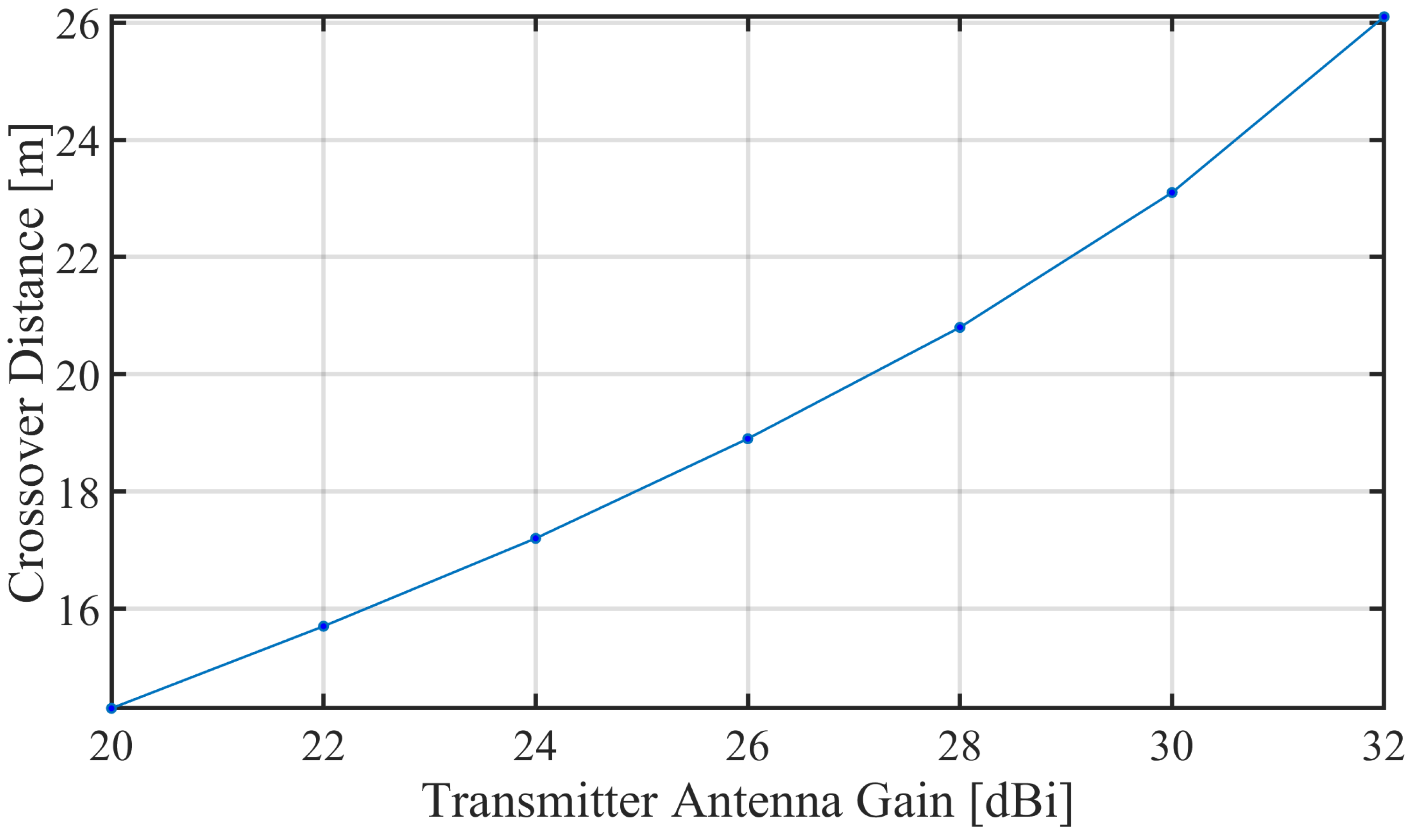
Figure 7 shows the relationship between antenna gain and the switching threshold for the hybrid method. Each point on the graph is extracted from the intersection of the performance curves in Figure 6. From this, it is clear that as the antenna gain increases, the half-power beamwidth (HPBW) becomes narrower, which in turn extends the threshold distance required to accommodate the GNSS positioning error. Based on these results, since the gain of the 16 × 16 array antenna used in our simulation is approximately 26 dBi, we set the switching threshold to 19 m for all subsequent simulations.There is a possibility of chattering due to frequent switching between GNSS and the camera when the UAV moves back and forth near the boundary. For example, switching from GNSS to the camera could occur at 19 m, while switching from the camera back to GNSS could occur at 21 m—having two different thresholds could be useful. However, in this simulation, since the scenario involves continuously varying distances, hysteresis thresholds are not considered, and the handling of hysteresis is left for future work.

3. Simulation Setup

3.1. Simulation Environment

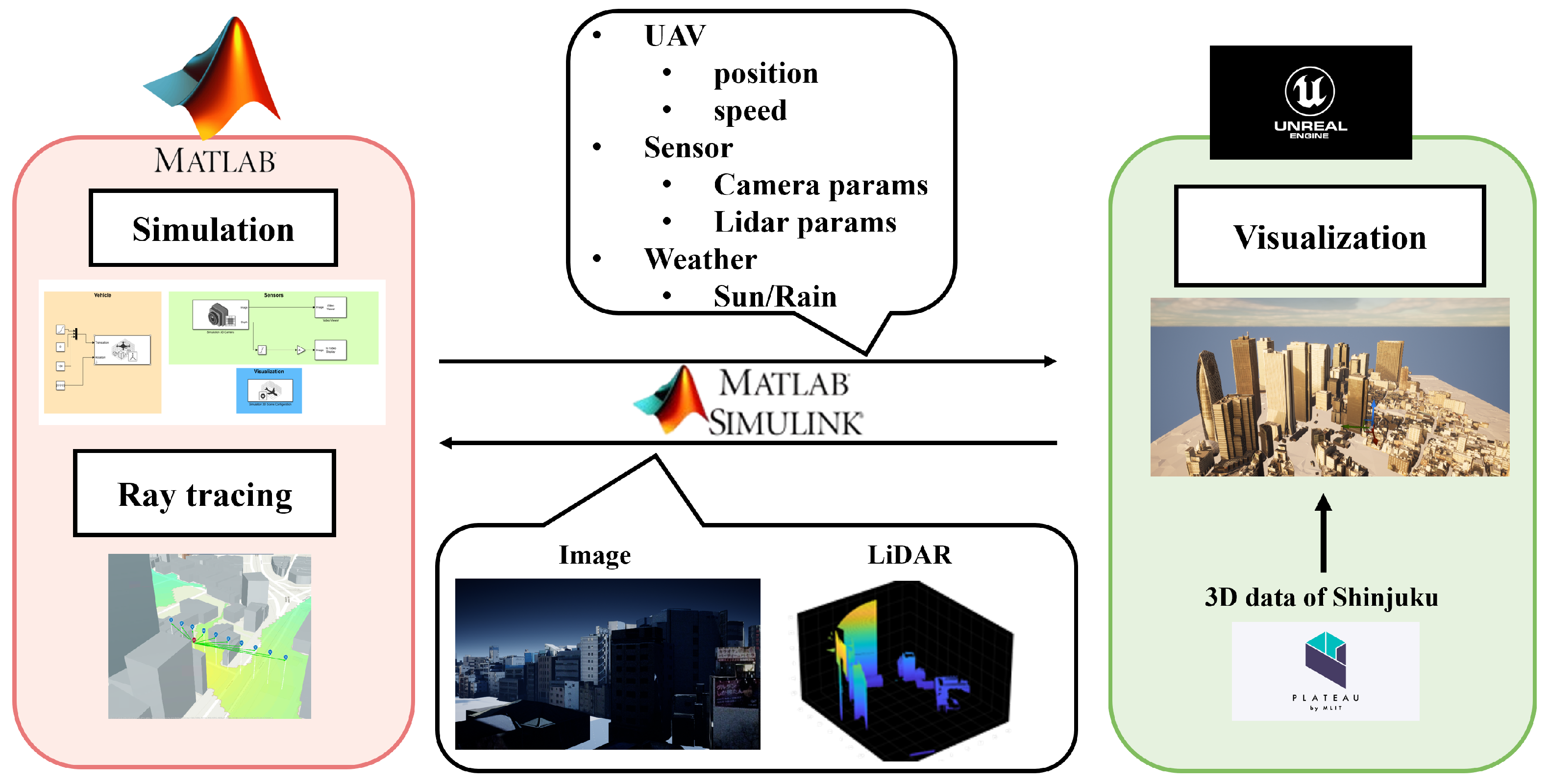
To evaluate our method, we constructed a high-fidelity co-simulation environment by integrating MATLAB/Simulink and Unreal Engine (UE), as depicted in Figure 8. In this setup, a 3D model of Shinjuku, Tokyo, is rendered in UE to generate realistic camera and LiDAR sensor data. This data is then fed to MATLAB/Simulink, which executes our proposed perception and beam control algorithms and performs ray-tracing analysis for mmWave propagation. This framework allows for a precise evaluation of our system’s performance in a challenging and realistic urban environment.

3.2. Scenarios and Parameters

This section details the flight scenario, the parameters for the communication and perception modules, and those used for the baseline methods. We conduct simulations for two scenarios in this study. The first is a short-range scenario, limited to approximately 10 m, designed to demonstrate the effectiveness of the proposed Camera/LiDAR method. The second is a short-to-mid-range scenario, extending up to approximately 30 m, which is used to show the effectiveness of our hybrid approach. In the latter scenario, we validate the benefit of adaptively switching methods based on the distance to the target.
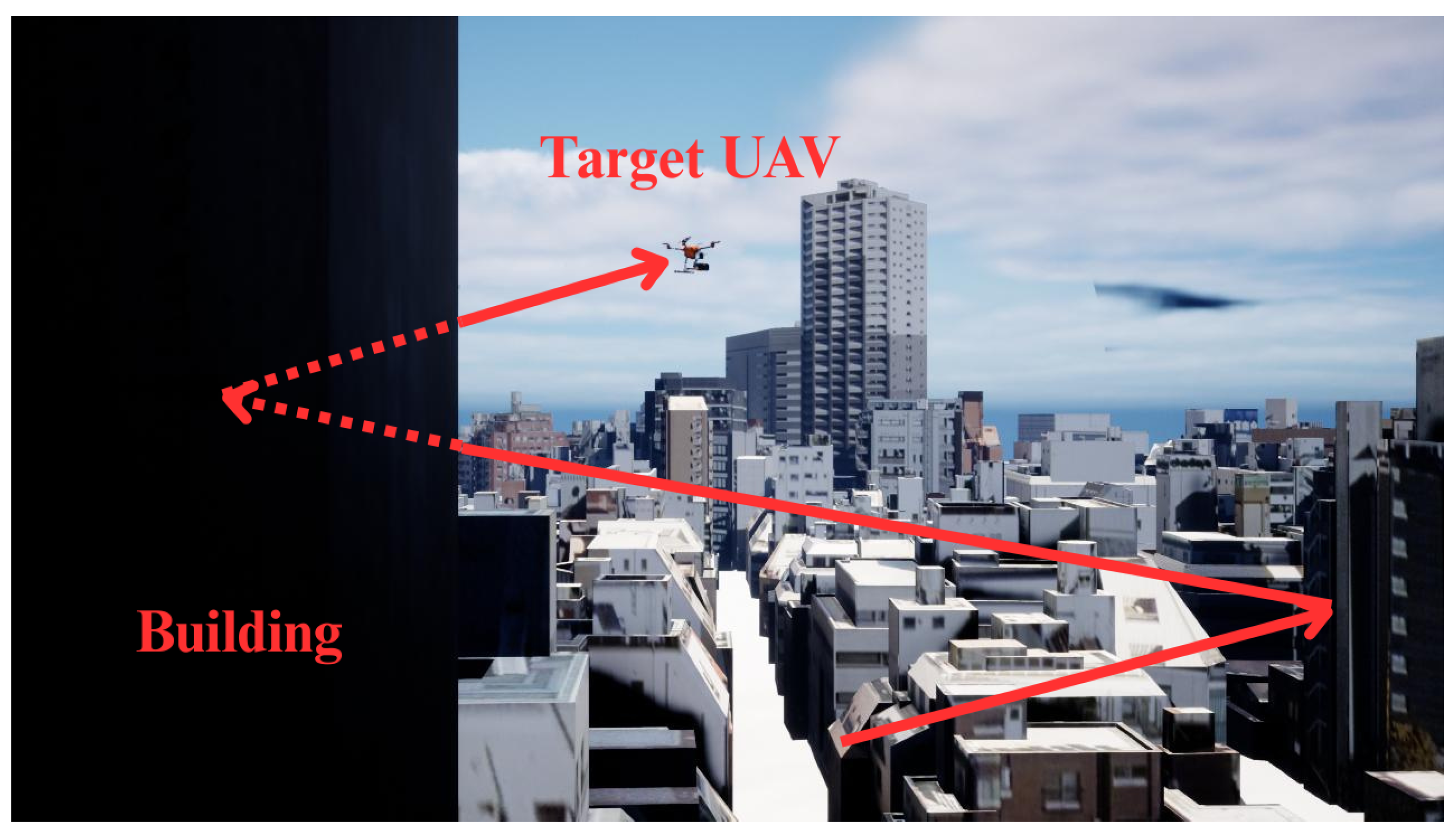
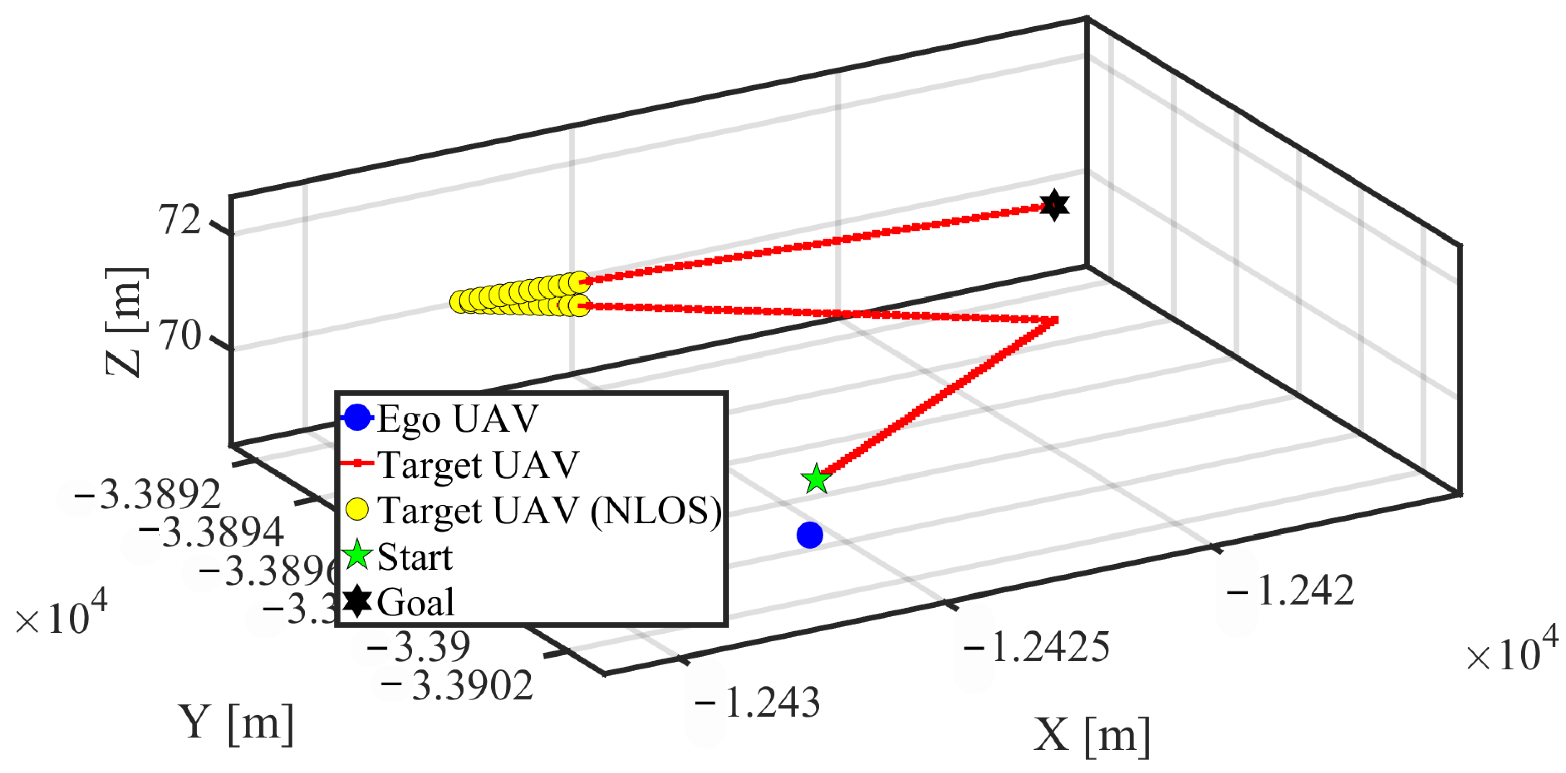
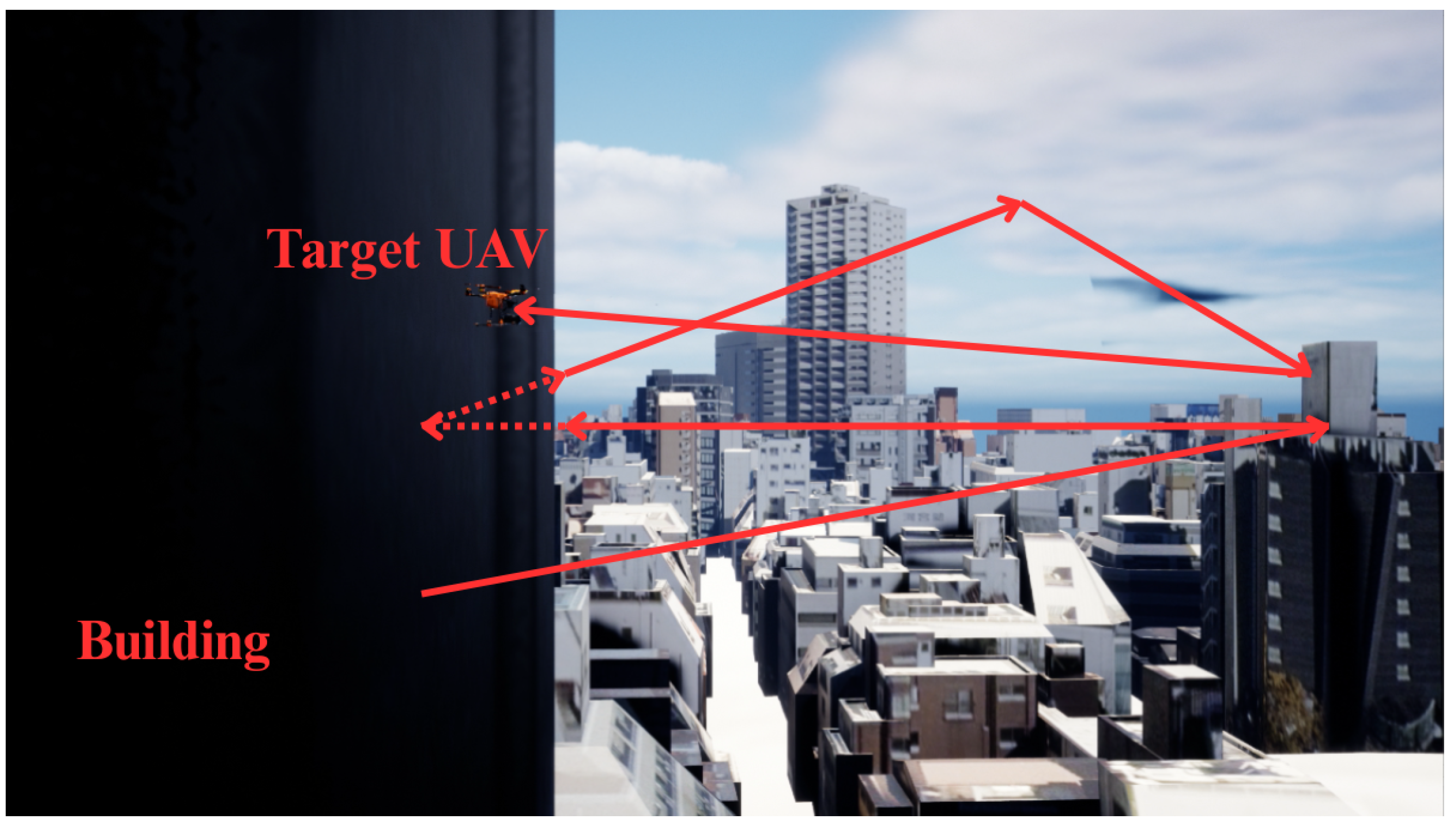
The first flight scenario used for our evaluation is depicted in Figure 9 (2D relative path) and Figure 10 (3D path). The ego UAV hovers at a fixed altitude of 70 m, while the target UAV executes a zig-zag maneuver with a gradual increase in altitude. Notably, this path includes a segment where the line of sight is intentionally obstructed by a building, creating a Non-Line-of-Sight (NLOS) condition. This allows for the evaluation of the link recovery performance of the beam sweeping baseline method. This scenario is designed to demonstrate the effectiveness of the Camera/LiDAR sensor fusion method at short range; therefore, the hybrid approach is not evaluated here. Even if the hybrid method were used, all target UAVs are positioned closer than the switching threshold, meaning the Camera/LiDAR method would be selected in all cases anyway.
The second scenario, similar to the first, includes a Non-Line-of-Sight (NLOS) segment and features linear trajectories at various distances. Figure 11 and Figure 12 show 2D relative path and 3D path. While the number of data points and the stationary (hovering) state of the transmitter remain the same, the inter-UAV distance differs, extending to a maximum of approximately 30 m. To measure the difficulty of tracking at close range, the trajectory includes segments where the receiver traverses a straight path at both short and medium distances. Even when moving at the same linear velocity, the angular rate is higher at shorter distances, making tracking particularly challenging for the GNSS-based method. This second scenario includes a variety of distances specifically to demonstrate the effectiveness of the hybrid approach. As the effectiveness of the Camera/LiDAR method was already shown in Scenario 1, we use this scenario to illustrate how the hybrid method improves spectral efficiency over a wider operational range by combining the two techniques.
Table 1 summarizes the simulation parameters for the communication and propagation model. Our study assumes a millimeter-wave system operating at 60 GHz with an 16 × 16 Uniform Rectangular Array (URA) antenna. In the current simulation setup, the number of reflections is set to zero for simplicity; therefore, the effects of multipath propagation are not considered. This is because the camera-based detection range is relatively short, where the direct path is dominant. While the channel fundamentally follows a two-ray propagation model, the influence of scatterers diminishes as the UAV altitude increases [31]. At 60 GHz, which is used in our simulation, attenuation is high, and the direct wave is dominant at short ranges, rendering the ground reflection negligible. The simulation employed a ray-tracing-based propagation model that includes building geometries, with the maximum number of reflections set to zero. Consequently, the channel is modeled as either a line-of-sight (LOS) path or a complete blockage by buildings. As a result, no multipath components occur in this simulation, and the delay spread remains zero throughout.
For the perception module, we trained a tiny-yolov4-coco model on a custom dataset of 2730 manually labeled images captured across multiple flight scenarios. The model was trained for a maximum of 40 epochs using the Adam optimizer, with a mini-batch size of 4, an initial learning rate of 10 3 , and an L2 regularization factor of 5 × 10 4 . It was trained on a custom dataset, which was manually labeled from images captured across multiple flight scenarios.
The parameters for the baseline methods are detailed as follows. For the GNSS-based baseline, we utilized the built-in GPS model in MATLAB, assuming a relatively accurate receiver by setting the standard deviation of the horizontal and vertical position errors to 0.24 m and 0.45 m, respectively, with an update rate of 10 Hz. The beam sweeping method employs a hierarchical search for initial link acquisition and recovery. This consists of a two-stage process: a coarse search with 12 beams at a 30° spacing covering a 90° × 60° range, followed by a fine search with 16 beams at a 10° spacing. For tracking, a more efficient local search of 9 beams with a 10° spacing is used. The threshold for determining a link loss is set to an SNR of 5 dB.

3.3. Processing Latency Model

To model the low-latency performance of each method, we introduced processing latencies into our 60 Hz (16.7 ms time step) simulation. The latency of our Camera/LiDAR method is modeled based on empirical measurements: the perception stage (YOLO detection: 32.75 ms; Clustering: 6.53 ms) and the beam control stage (0.02 ms) result in a total end-to-end processing time of approximately 40 ms, which corresponds to a 3-step delay. For the baselines, the codebook-based method, with its timing referenced from the IEEE 802.11ad standard [32] and related work [33], is modeled to require a 106 ms latency (7-step delay) for initial acquisition and a 16.7 ms latency (1-step delay) for tracking. The GNSS-based method’s latency is governed by its 10 Hz update rate, resulting in a maximum delay of 100 ms (a 6-step delay).

3.4. Evaluation Metrics

To quantitatively evaluate the performance of our proposed system from multiple perspectives, we define metrics in two categories: “Detection Performance” and “Communication Link Performance.”

3.4.1. Detection Performance Metrics

We evaluate the detection performance of our proposed camera–LiDAR fusion method against a LiDAR-only baseline [18]. To assess the accuracy of UAV detection, we use three standard metrics. Precision is the ratio of correctly predicted positive observations to the total predicted positive observations and measures the rate of false positives. Recall is the ratio of correctly predicted positive observations to all observations in the actual class, which indicates detection comprehensiveness by measuring the rate of false negatives. Finally, the F1-Score is the harmonic mean of Precision and Recall, serving as a single comprehensive score that balances both metrics.
In this study, the spatial tolerance for a “detection success” (within 0.48 m) is defined based on two perspectives: the physical airframe size of the UAV (0.48 m), and the “pointing error,” which directly impacts beamforming performance. For example, the half-power beamwidth (HPBW) of the 16 × 16 array antenna is approximately 6.4 degrees, which corresponds to a beam width of about 2.2 m at a mid-range distance (e.g., 20 m) in our scenario. The 0.48 m tolerance we defined is set as a realistic value to ensure that the target’s center is captured well within this beamwidth, thereby maintaining a high-gain communication link.

3.4.2. Communication Link Performance Metrics

To evaluate the effectiveness of the beamforming control, we use the following three metrics:
  • Spectral Efficiency ( η ): A measure of how efficiently a given bandwidth is utilized. It is calculated by dividing the throughput by the bandwidth. We calculate the theoretical maximum channel capacity (C) based on the Shannon–Hartley theorem as the throughput.
    η = C B = log 2 ( 1 + SNR )
    where B is the bandwidth and SNR is the Signal-to-Noise Ratio.
  • Angular Pointing Error ( E angle ): An indicator of beam alignment accuracy. It is calculated as the angle between the steered beam vector ( v actual ) and the ground-truth vector to the target UAV ( v true ).
    E angle = arccos ( v actual · v true | v actual | | v true | )
We define the angular error as 180° during the initial acquisition delay to ensure the average error metric properly penalizes methods with longer latencies.

4. Results

4.1. Detection Performance

Table 2 shows the confusion matrix for the proposed method and the LiDAR-only baseline. From this matrix, we calculated the Precision, Recall, and F1-score, which are summarized in Table 3. The Camera/LiDAR fusion-based method demonstrates a remarkable improvement over the LiDAR-only baseline [18], particularly in Precision. This is primarily because our method leverages visual information from the camera to effectively reject non-UAV objects (e.g., parts of buildings, trees) that are difficult to distinguish using only LiDAR point cloud geometry. In contrast, the baseline method, which relies solely on geometric features like cluster size and point density, was more prone to false positives (FP) by misidentifying similarly-sized objects as UAVs.
On the other hand, the difference in Recall between the two methods was marginal. This suggests that both approaches face similar challenges in scenarios where the sensors fail to capture the target adequately, such as when the target UAV is at a long distance or against a cluttered background.
Consequently, the F1-score, which balances both metrics, shows a substantial improvement of 22.7% for our Camera/LiDAR method over the baseline, driven largely by the significant gain in Precision. This result demonstrates that our sensor fusion approach is highly effective in improving overall detection reliability by suppressing false positives.

4.2. Communication Link Performance (Scenario 1)

Next, we evaluate the beam control performance by analyzing how the Angular Pointing Error impacts the Spectral Efficiency.

4.2.1. Analysis of Angular Pointing Error

Figure 13 shows the time-series variation in the angular pointing error for each method. While the angular error is defined as 180° for all methods during the initial acquisition delay, the y-axis has been zoomed in to better visualize the detailed error fluctuations during tracking. The GNSS-based method exhibits irregular and significant error spikes due to positioning inaccuracies caused by multipath effects in the urban environment. The beam sweeping method, which selects beam directions from a predefined codebook, suffers from quantization error when the target UAV is located between the discrete beam directions, resulting in a periodically fluctuating angular error.Furthermore, this method exhibits exceptionally large errors during the NLOS phase. This is because beam sweeping is a reactive method based solely on channel quality, with no knowledge of the target’s actual position. During NLOS, the algorithm may lock onto a weak reflection from a completely incorrect direction, causing the beam to deviate significantly from the true target location. In contrast, while our Camera/LiDAR method also loses its sensor lock in NLOS, it holds the last known beam direction, preventing such drastic error spikes.
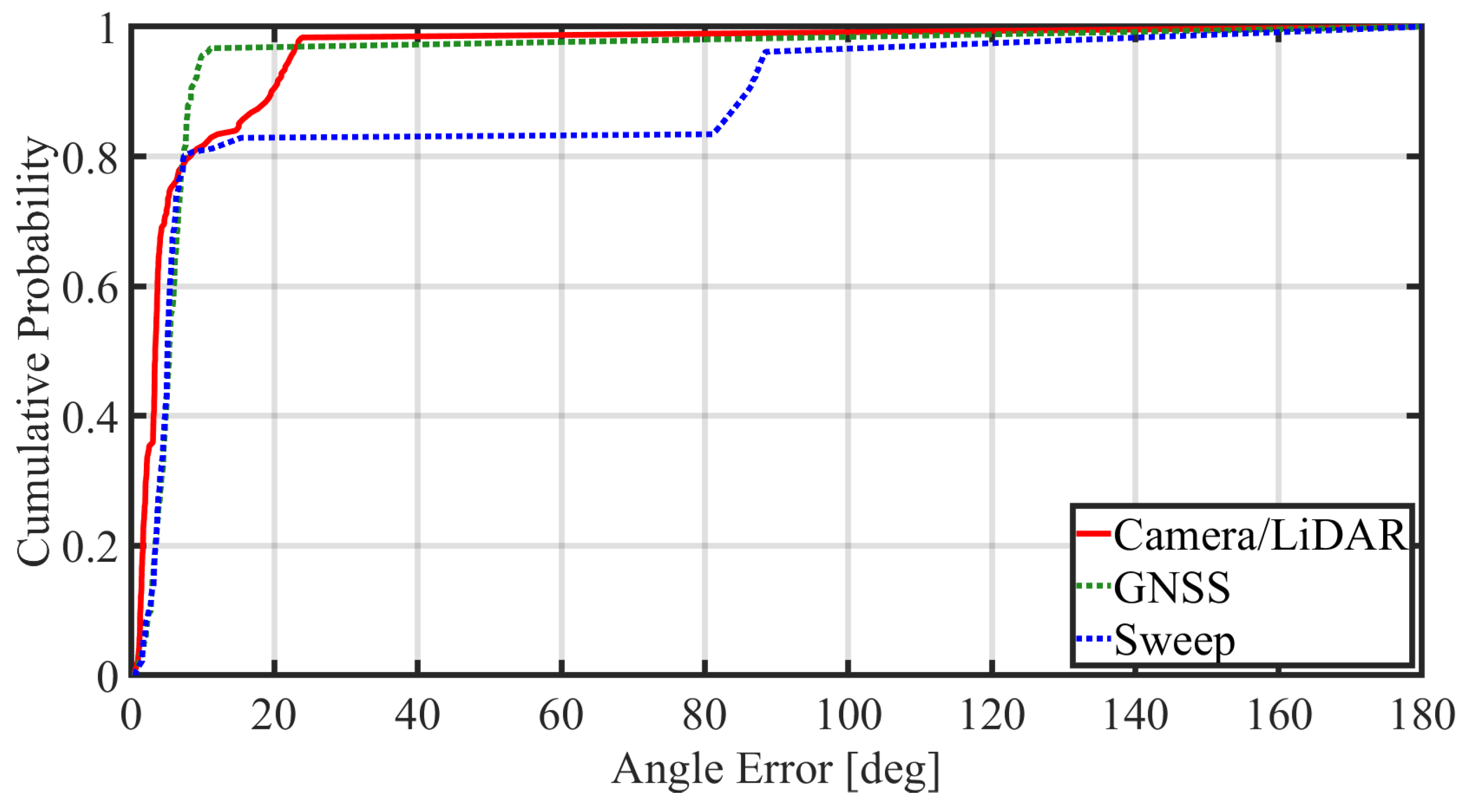
In contrast, our Camera/LiDAR method, which directly perceives the target, is immune to these error sources and maintains a low and stable angular error that closely tracks the ideal (ground truth) case. As shown in Table 4, the Camera/LiDAR method achieves a lower angular error than the baseline methods, despite the presence of NLOS conditions. Figure 14 shows the CDF of the angular error. Accounting for the about 14% (25/181) outage from the NLOS period, the 80th percentile clearly demonstrates the superiority of the Camera/LiDAR method.

4.2.2. Comparison of Spectral Efficiency

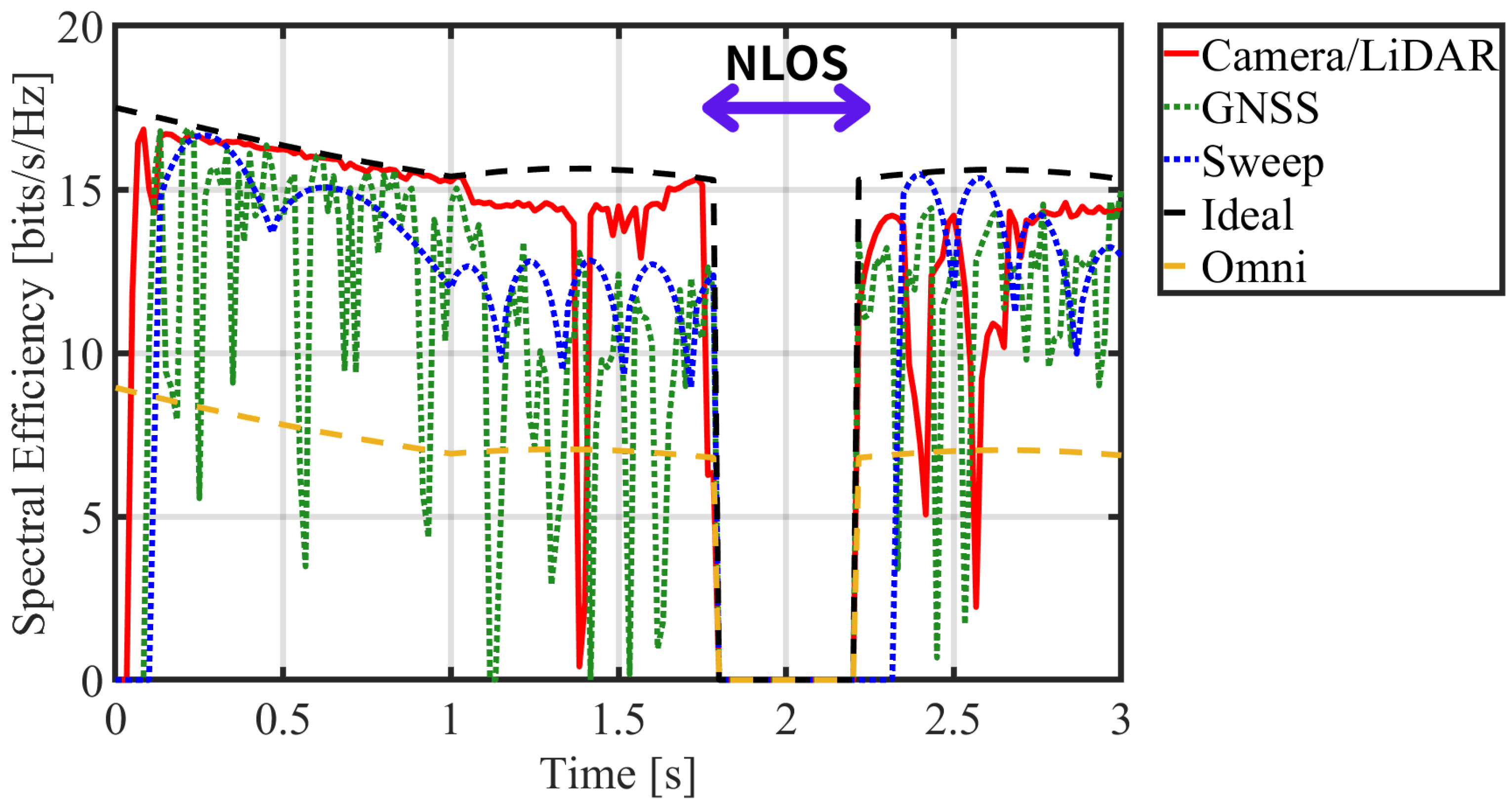
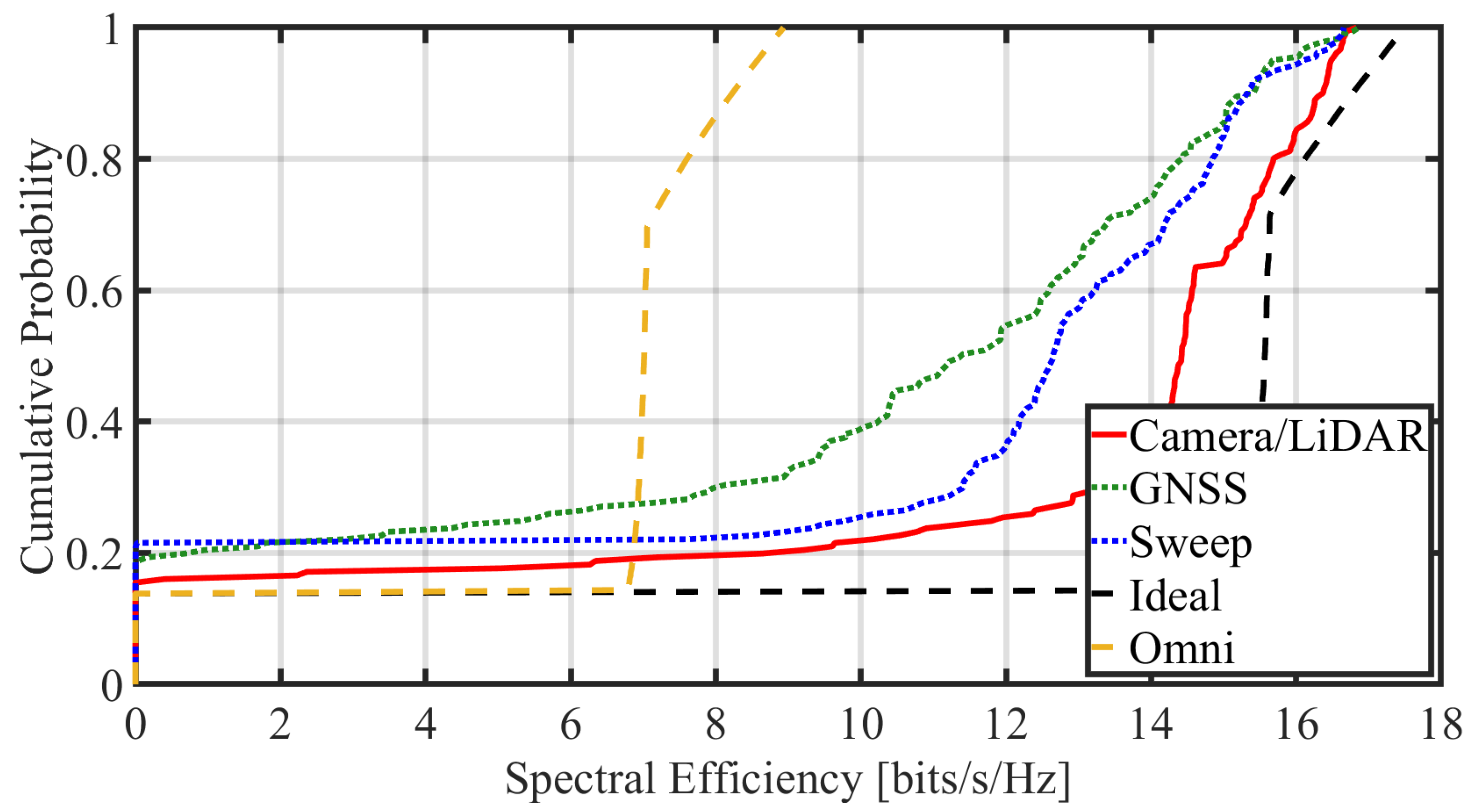
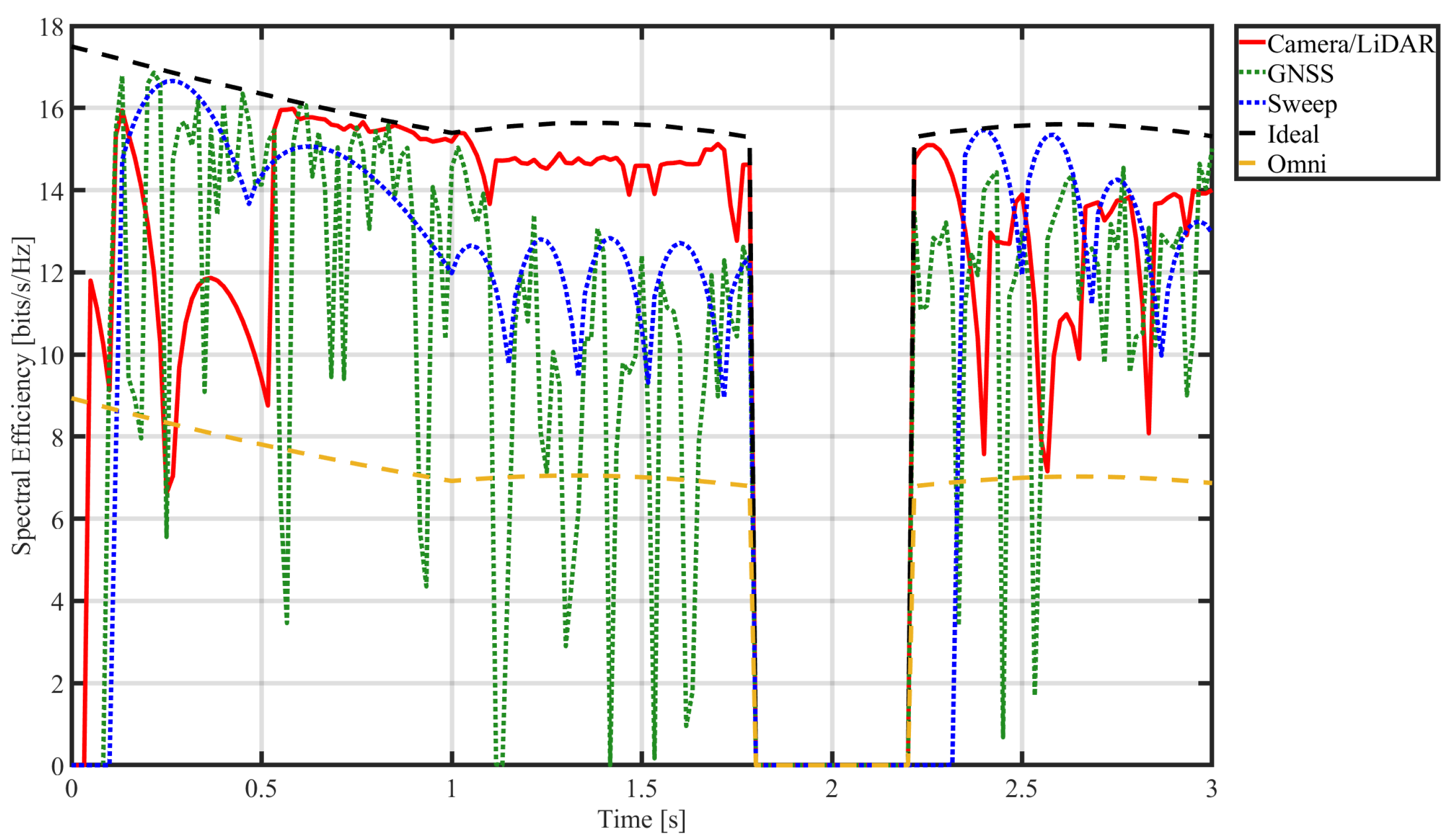
This difference in pointing accuracy is directly reflected in the spectral efficiency, as shown in Figure 15. By consistently maintaining a low angular error, the Camera/LiDAR method achieves a high and stable spectral efficiency that approaches the ideal state. The spectral efficiency of the GNSS-based method drops sharply in sync with its angular error spikes, while the beam sweeping method’s efficiency fluctuates according to its quantization error. Furthermore, the comparison with the omni-antenna baseline confirms that the beamforming provided by our method significantly enhances channel capacity.
Quantitatively, the Camera/LiDAR method achieved the highest average spectral efficiency of 11.98 bits/s/Hz, significantly outperforming the GNSS-based (9.54 bits/s/Hz) and beam sweeping (10.52 bits/s/Hz) methods.
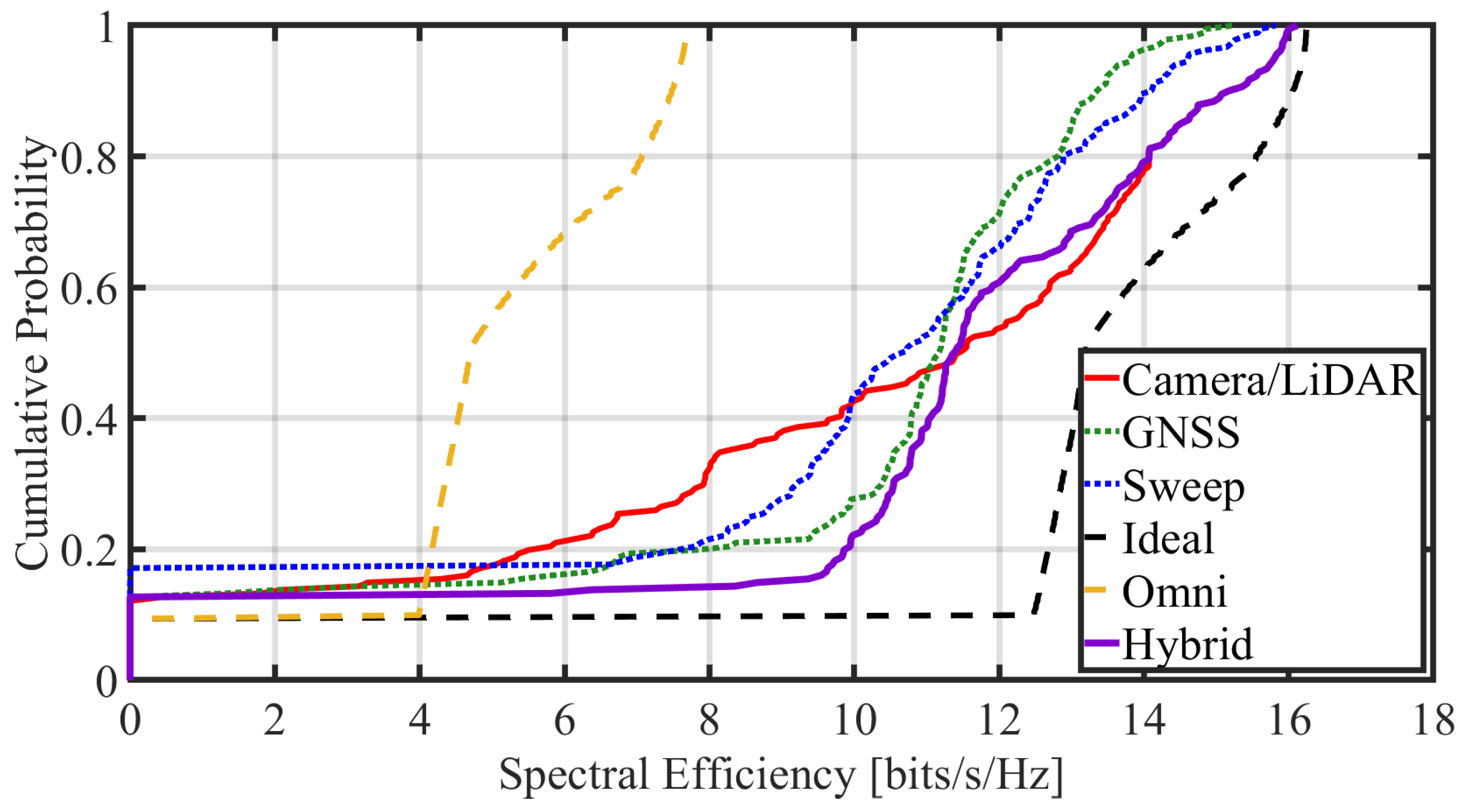
Given the large fluctuations in the time-series data, the CDF of spectral efficiency in Figure 16 provides a clearer view of the performance distribution. The curve for the Camera/LiDAR method most closely tracks that of the ideal state.

4.2.3. Link Acquisition and Recovery Speed

For applications such as UAV relaying, the speed of link acquisition and recovery is as critical as the average performance. Focusing on the beginning of the simulation in Figure 15, our Camera/LiDAR method establishes the link almost instantaneously, with its spectral efficiency rising rapidly. The beam sweeping method, however, shows a significant delay in link establishment due to its time-consuming initial exhaustive search. This rapid initial acquisition is a key advantage of our approach.
Furthermore, a similar delay is observed for the beam sweeping method during the recovery phase after the NLOS period. This occurs because when the UAV moves behind a building and the SNR drops below the threshold, the system declares a link loss and re-initiates its time-consuming initial acquisition sequence (the full search). Given that UAVs in urban environments are frequently occluded, as in our scenario, this ability to recover the link quickly from NLOS is another significant advantage of our Camera/LiDAR method.

4.3. Communication Link Performance (Scenario 2)

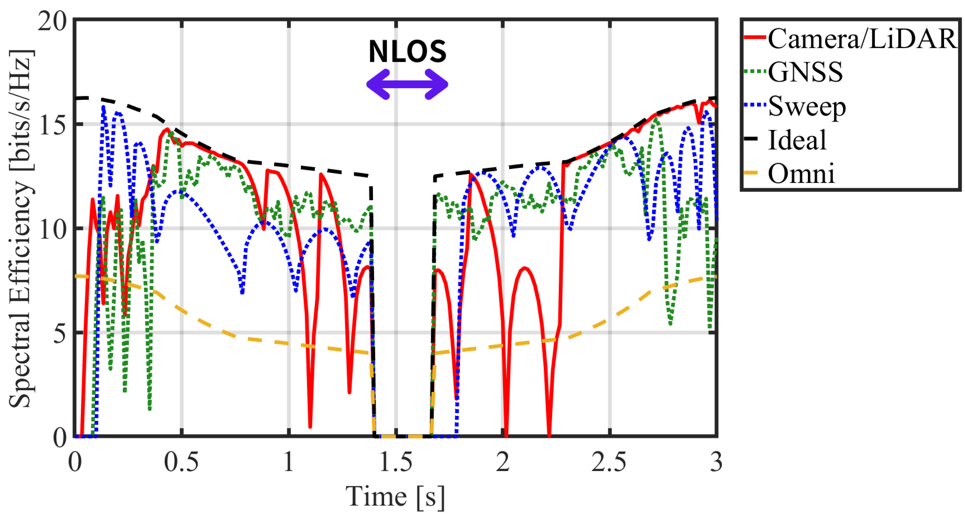
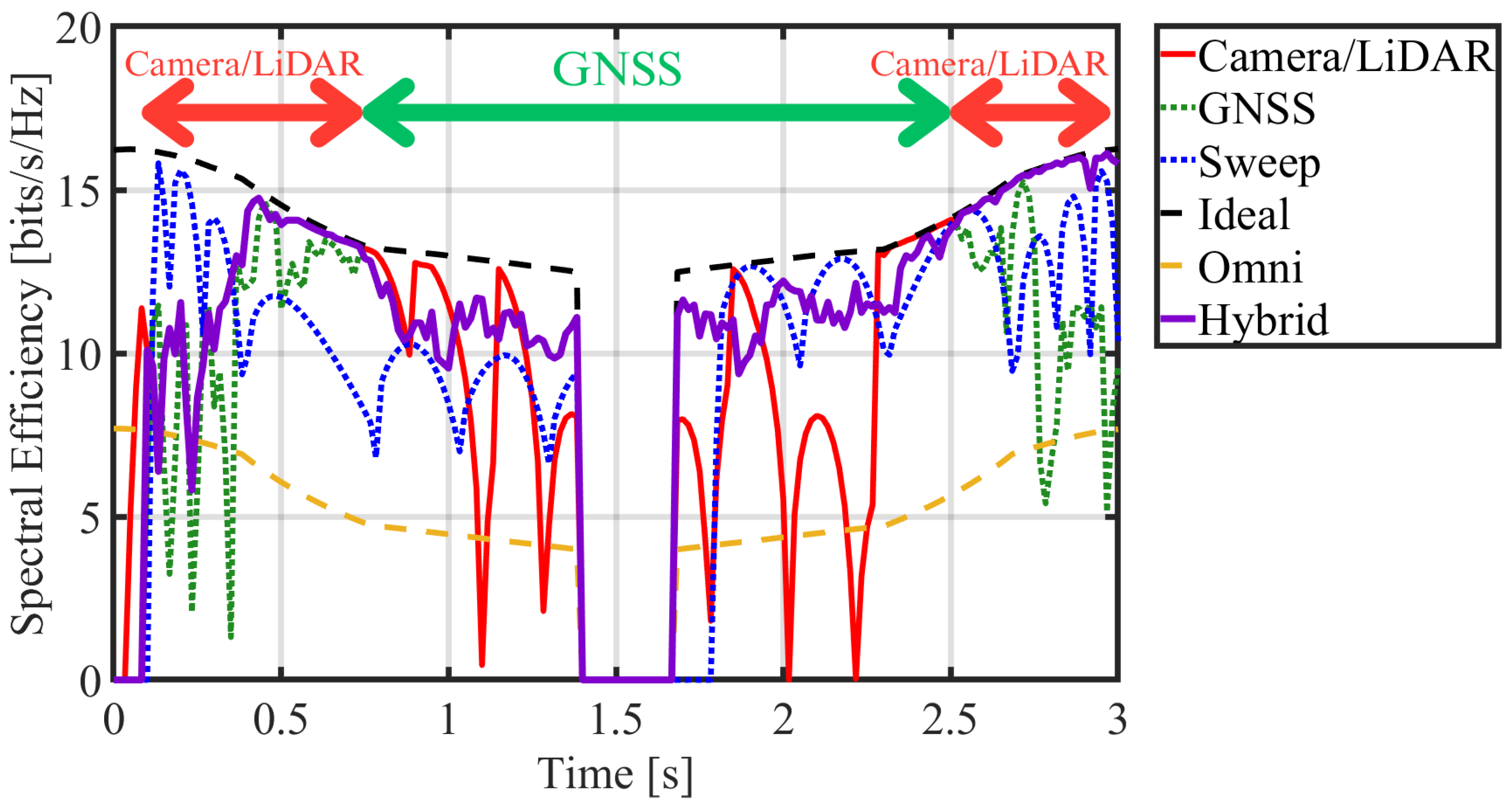
Next, we will analyze the hybrid approach from Scenario 2. Since the respective characteristics, advantages, and disadvantages of each individual method were already discussed in Scenario 1, this section will focus specifically on the unique results of the hybrid method. Figure 17 shows the spectral efficiency and Figure 18 shows how hybrid method switches.
First, As described in the previous Section 2.5, the switching threshold for the hybrid approach is set to 19 m, based on the results of our preliminary experiments. Figure 19 illustrates the actual switching behavior of the system as a function of distance. Observing the range beyond 19 m, it is evident that the red line, representing the Camera/LiDAR method, becomes erratic. This is because the detection accuracy degrades significantly beyond 19 m. In this same range, the GNSS method, despite its inherent errors, demonstrates relatively constant throughput, indicating higher stability. Focusing on the range within 19 m, the GNSS method often fails to keep the target within the beam’s half-power beamwidth due to large positioning errors, resulting in a considerable drop in throughput and significant fluctuations. This is because at close range, the high angular rate of the target causes large tracking errors due to the latency from the GNSS update rate. In contrast, the Camera/LiDAR method, while showing some initial detection ambiguity at the link establishment phase, achieves a throughput nearly equivalent to the Ideal case after 2.5 s. The Beam Sweep method exhibits an oscillating throughput. This is because it can only steer to discrete angles, and with the narrower beamwidth used in this scenario, the pointing errors become more pronounced.
Second, observing the CDF values (Figure 20), in the low-to-mid performance region, the Camera/LiDAR method accounts for a high cumulative probability, whereas the Hybrid method shows the lowest. This is because, as shown in the previous figure, the camera’s detection accuracy degrades significantly at ranges beyond 19 m. In the high-performance region, on the other hand, the Camera/LiDAR and Hybrid methods demonstrate nearly identical performance. There is a point in the mid-performance range where the Camera/LiDAR method momentarily surpasses the Hybrid method. This can be attributed to instances where the camera successfully detects the target even beyond 19 m, yielding a slightly higher throughput that allows it to outperform the Hybrid method in those moments. While the distribution of the GNSS method is similar to the Hybrid method, the Hybrid method’s curve is positioned further to the right on the CDF graph because it incorporates the high-accuracy detection of the Camera/LiDAR method at short ranges. Overall, in this scenario which includes both short and long ranges, the performance of the Camera/LiDAR method is widely distributed, making it difficult to describe as a stable communication link. In contrast, the Hybrid method compensates for the respective weaknesses of the Camera/LiDAR and GNSS methods, demonstrating consistently high performance. Table 5 shows the average spectral efficiency. The hybrid method achieves 8.5% higher efficiency compared to the Camera/LiDAR method.

4.4. Resistance to Rain

To validate the resilience of the proposed system, its performance must be evaluated under realistic adverse weather conditions. Rain, in particular, poses a significant operational challenge for a system relying on Camera/LiDAR sensors, as precipitation can degrade detection accuracy by obstructing the lens or scattering the signal. To quantify this impact, we conducted simulations comparing the system performance in a clear-weather scenario against scenarios with varying intensities of rain. This section presents a comparative analysis of the resulting communication quality, focusing on spectral efficiency, to assess the robustness of our approach against such environmental factors.
Prior research exists regarding UAV detection in rainy environments using object detection algorithms based on YOLOv5 [34]. One such study employs DID-MDN (Density-aware Image De-raining using a Multi-stream Dense Network), a deep learning-based image restoration network, to remove rain streaks from images. This approach achieved a Mean Average Precision (mAP) of 0.8 for detecting aerial objects such as UAVs and birds. Similarly, other research comparing YOLOv5, YOLOv8, and Faster-RCNN on datasets augmented with artificial rain also demonstrated that YOLO models can maintain favorable mAP performance [35]. In this study, however, we do not employ such pre-processing algorithms. Instead, we simulate the degradation in communication performance under rainy conditions using a YOLO model that was trained exclusively on clear-weather (rain-free) data.
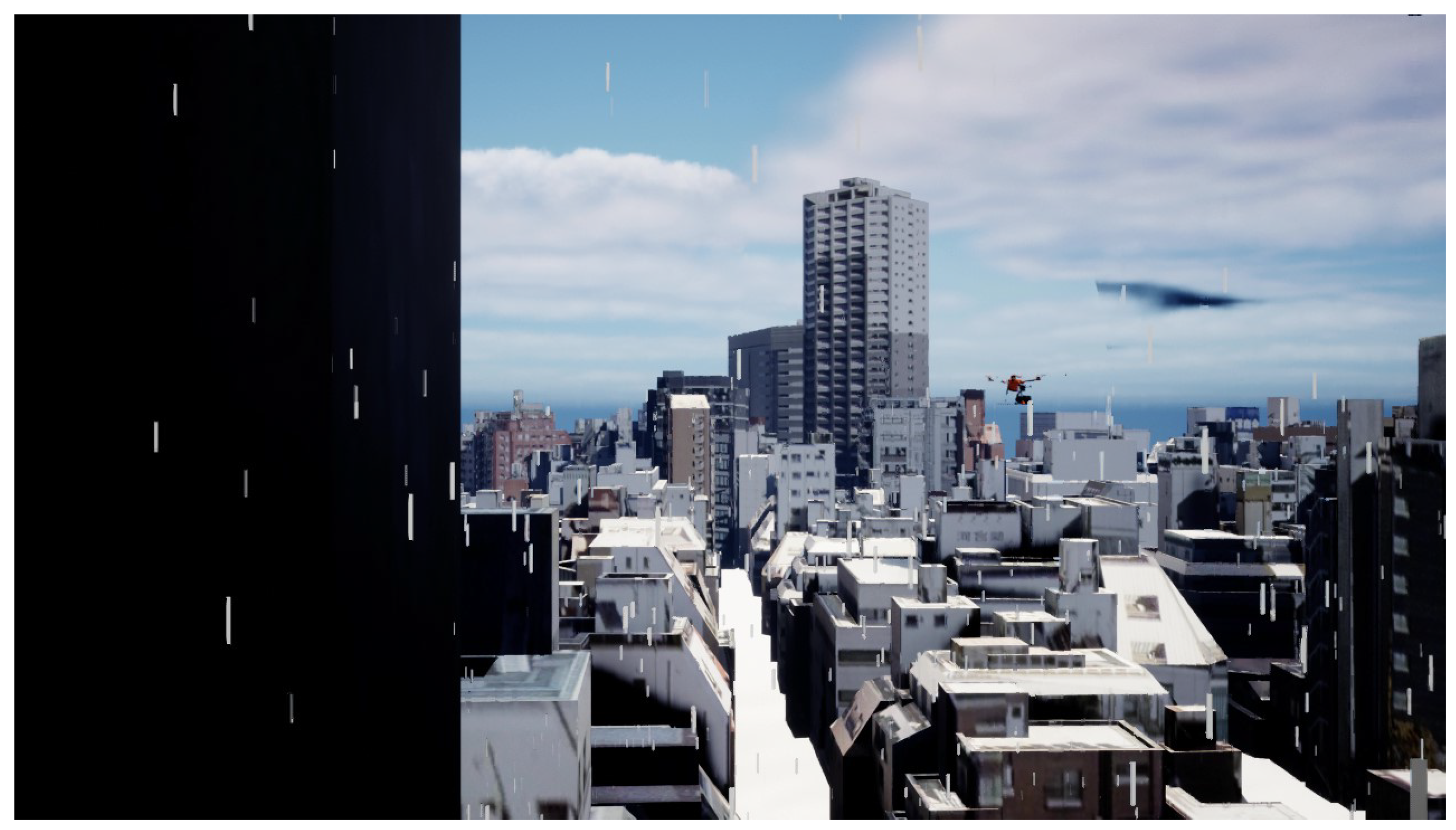
Figure 21 depicts the simulation environment under rainy conditions. This scenario is identical to those in Figure 9 and Figure 10, with the sole exception of the added precipitation, allowing for a direct comparison to isolate the degradation in communication quality caused by rain. Figure 22 presents the spectral efficiency over time. Compared to the clear-weather case (Figure 15), the communication quality is notably degraded for the first 0.5 s. As shown in Table 6, while the average spectral efficiency decreases from 11.98 bits/s/Hz (clear) to 11.58 bits/s/Hz (rain), the proposed method still maintains a higher performance level than the other benchmark methods.
Figure 23 presents the CDF of spectral efficiency. While average performance is important, the ability to sustain high-efficiency communication is critical. Therefore, we use the 10-percentile value (representing 90% availability) as a key metric for stability, which indicates the performance level maintained for at least 90% of the operational time. It should be noted that because this scenario includes building obstructions causing NLOS, all non-communicable data points were excluded from this calculation; the analysis is performed only on the LOS segments. As shown in Table 7, the 10-percentile value for the Camera/LiDAR method degrades from 10.54 bits/s/Hz in clear weather to 10.28 bits/s/Hz in rain. This, however, represents a minor degradation of only 2.5%, and the system maintains a high-performance floor compared to other methods, demonstrating its resilience against rain.

5. Conclusions

In this paper, we proposed a fully autonomous beam steering system that utilizes LiDAR and camera sensor fusion to address the challenges in conventional inter-drone communication, such as GNSS dependency and beam sweeping latency. The novelty of our approach lies in the end-to-end pipeline that achieves low-latency target UAV detection and precise beamforming without reliance on external infrastructure.
Through simulation-based evaluation, we demonstrated that the proposed system significantly improves beam pointing accuracy, resulting in a substantial increase in average spectral efficiency compared to baseline methods (GNSS-based and codebook-based). This achievement is a significant step toward realizing highly reliable aerial relay networks and is expected to be applicable to future advanced UAV applications, including formation flight and high-density traffic scenarios.
As a further extension, we proposed a hybrid approach that combines our Camera/LiDAR method for short-range scenarios with the GNSS-based method for mid-to-long-range communication. This strategy successfully extends the communication coverage by delegating to GNSS in areas beyond the camera’s effective detection range. By compensating for the respective disadvantages of each individual method, the hybrid approach ultimately demonstrated the highest overall spectral efficiency.
This study has limitations, including a vulnerability to adverse weather, an assumption of LoS-only conditions, and remaining processing delay. Future work will focus on incorporating a predictive tracking mechanism for more agile targets, extending the system to a multi-drone network to investigate autonomous handover and resource management. Furthermore, this simulation does not yet account for complex real-world factors such as MAC/PHY overhead, beam training costs, and wind-induced jitter. Incorporating these factors remains an important area for future work.

Author Contributions

Conceptualization, Y.S. and G.K.T.; Methodology, Y.S. and G.K.T.; Software, Y.S.; Validation, Y.S.; Formal analysis, Y.S.; Investigation, Y.S.; Resources, Y.S.; Data curation, Y.S.; Writing—original draft, Y.S.; Writing—review & editing, Y.S. and G.K.T.; Visualization, Y.S.; Supervision, Y.S. and G.K.T.; Project administration, Y.S. and G.K.T.; Funding acquisition, Y.S. and G.K.T. All authors have read and agreed to the published version of the manuscript.

Funding

This research was partially funded by JSPS KAKENHI Grant Number 25K15090 and 24K00940.

Data Availability Statement

The original contributions presented in this study are included in the article. Further inquiries can be directed to the corresponding authors.

Conflicts of Interest

The authors declare no conflicts of interest.

References

  1. Tran, G.K. Temporary Communication Network Using Millimeter-Wave Drone Base Stations. In Proceedings of the 2024 IEEE VTS Asia Pacific Wireless Communications Symposium (APWCS), Singapore, 21–23 August 2024. [Google Scholar]
  2. Tran, G.K.; Nakazato, J.; Sou, H.; Iwamoto, H. Research on smart wireless aerial networks facilitating digital twin construction. IEICE Trans. Commun. 2026, E109-B, 4. [Google Scholar] [CrossRef]
  3. Tran, G.K.; Ozasa, M.; Nakazato, J. NFV/SDN as an Enabler for Dynamic Placement Method of mmWave Embedded UAV Access Base Stations. Network 2022, 2, 479–499. [Google Scholar] [CrossRef]
  4. Sumitani, T.; Tran, G.K. Study on the construction of mmWave based IAB-UAV networks. In Proceedings of the AINTEC 2022, Hiroshima, Japan, 19–21 December 2022. [Google Scholar]
  5. Amrallah, A.; Mohamed, E.M.; Tran, G.K.; Sakaguchi, K. UAV Trajectory Optimization in a Post-Disaster Area Using Dual Energy-Aware Bandits. Sensors 2023, 23, 1402. [Google Scholar] [CrossRef] [PubMed]
  6. Yang, L.; Zhang, W. Beam Tracking and Optimization for UAV Communications. IEEE Trans. Wirel. Commun. 2019, 18, 5367–5379. [Google Scholar] [CrossRef]
  7. Zhou, S.; Yang, H.; Xiang, L.; Yang, K. Temporal-Assisted Beamforming and Trajectory Prediction in Sensing-Enabled UAV Communications. IEEE Trans. Commun. 2025, 73, 5408–5419. [Google Scholar] [CrossRef]
  8. Miao, W.; Luo, C.; Min, G.; Zhao, Z. Lightweight 3-D Beamforming Design in 5G UAV Broadcasting Communications. IEEE Trans. Broadcast. 2020, 66, 515–524. [Google Scholar] [CrossRef]
  9. Dovis, F. GNSS Interference Threats and Countermeasures; Artech House: Norwood, MA, USA, 2015. [Google Scholar]
  10. Zhou, J.; Wang, W.; Zhang, C. A GNSS Anti-Jamming Method in Multi-UAV Cooperative System. IEEE Trans. Veh. Technol. 2025; early access. [Google Scholar] [CrossRef]
  11. Abdelfatah, R.; Moawad, A.; Alshaer, N.; Ismail, T. UAV Tracking System Using Integrated Sensor Fusion with RTK-GPS. In Proceedings of the International Mobile, Intelligent, and Ubiquitous Computing Conference (MIUCC), Cairo, Egypt, 26–27 May 2021; pp. 352–356. [Google Scholar] [CrossRef]
  12. Zou, J.; Wang, C.; Liu, Y.; Zou, Z.; Sun, S. Vision-Assisted 3-D Predictive Beamforming for Green UAV-to-Vehicle Communications. IEEE Trans. Green Commun. Netw. 2023, 7, 434–443. [Google Scholar] [CrossRef]
  13. Liu, C.; Yuan, W.; Wei, Z.; Liu, X.; Ng, D.W.K. Location-Aware Predictive Beamforming for UAV Communications: A Deep Learning Approach. IEEE Wirel. Commun. Lett. 2021, 10, 668–672. [Google Scholar] [CrossRef]
  14. Zang, J.; Gao, D.; Wang, J.; Sun, Z.; Liang, S.; Zhang, R.; Sun, G. Real-Time Beam Tracking Algorithm for UAVs in Millimeter-Wave Networks with Adaptive Beamwidth Adjustment. In Proceedings of the 2025 International Wireless Communications and Mobile Computing (IWCMC), Abu Dhabi, United Arab Emirates, 12–16 May 2025; pp. 770–775. [Google Scholar] [CrossRef]
  15. Iwamoto, H. A Study on Characteristic Evaluation of Aerial Back-Haul Links by UAV for Digital Twin Construction. Master’s Thesis, Institute of Science Tokyo, Tokyo, Japan, 2025. (In Japanese). [Google Scholar]
  16. Zhong, W.; Zhang, L.; Jin, H.; Liu, X.; Zhu, Q.; He, Y.; Ali, F.; Lin, Z.; Mao, K.; Durrani, T.S. Image-Based Beam Tracking with Deep Learning for mmWave V2I Communication Systems. IEEE Trans. Intell. Transp. Syst. 2024, 25, 19110–19116. [Google Scholar] [CrossRef]
  17. Seidaliyeva, U.; Ilipbayeva, L.; Utebayeva, D.; Smailov, N.; Matson, E.T.; Tashtay, Y.; Turumbetov, M.; Sabibolda, A. LiDAR Technology for UAV Detection: From Fundamentals and Operational Principles to Advanced Detection and Classification Techniques. Sensors 2025, 25, 2757. [Google Scholar] [CrossRef]
  18. Zermas, D.; Izzat, I.; Papanikolopoulos, N. Fast segmentation of 3D point clouds: A paradigm on LiDAR data for autonomous vehicle applications. In Proceedings of the 2017 IEEE International Conference on Robotics and Automation (ICRA), Singapore, 29 May–3 June 2017; pp. 5067–5073. [Google Scholar]
  19. Shao, S.; Zhou, Y.; Li, Z.; Xu, W.; Chen, G.; Yuan, T. Frustum PointVoxel-RCNN: A High-Performance Framework for Accurate 3D Object Detection in Point Clouds and Images. In Proceedings of the 2024 4th International Conference on Computer, Control and Robotics (ICCCR), Shanghai, China, 19–21 April 2024; pp. 56–60. [Google Scholar]
  20. Sugimoto, Y.; Tran, G.K. A study on visual sensors based link quality prediction for UAV-to-UAV communications. In Proceedings of the 8th International Workshop on Smart Wireless Communications (SmartCom 2025), Eindhoven, The Netherlands, 4–6 June 2025. [Google Scholar]
  21. Sugimoto, Y.; Tran, G.K. Autonomous mmWave Beamforming for UAV-to-UAV Communication Using LiDAR-Camera Sensor Fusion. In Proceedings of the IEEE Global Communications Conference. 2025. Available online: https://t2r2.star.titech.ac.jp/cgi-bin/publicationinfo.cgi?lv=en&q_publication_content_number=CTT100937900 (accessed on 12 November 2025).
  22. Cai, X.; Zhu, X.; Yao, W. Distributed time-varying group formation tracking for multi-UAV systems subject to switching directed topologies. In Proceedings of the 27th International Conference on Computer Supported Cooperative Work in Design (CSCWD), Tianjin, China, 8–10 May 2024; pp. 127–132. [Google Scholar] [CrossRef]
  23. Ma, Z.; Zhang, R.; Ai, B.; Lian, Z.; Zeng, L.; Niyato, D.; Peng, Y. Deep Reinforcement Learning for Energy Efficiency Maximization in RSMA-IRS-Assisted ISAC System. In Proceedings of the IEEE Transactions on Vehicular Technology, Chengdu, China, 19–22 October 2025. [Google Scholar] [CrossRef]
  24. Ma, Z.; Liang, Y.; Zhu, Q.; Zheng, J.; Lian, Z.; Zeng, L.; Fu, C.; Peng, C.; Ai, B. Hybrid-RIS-Assisted Cellular ISAC Networks for UAV-Enabled Low-Altitude Economy via Deep Reinforcement Learning with Mixture-of-Experts. IEEE Trans. Cogn. Commun. Netw. 2025; early access. [Google Scholar] [CrossRef]
  25. Wang, J.; Zhu, Q.; Lin, Z.; Chen, J.; Ding, G.; Wu, Q.; Gu, G.; Gao, Q. Sparse Bayesian Learning-Based Hierarchical Construction for 3D Radio Environment Maps Incorporating Channel Shadowing. IEEE Trans. Wirel. Commun. 2024, 23, 14560–14574. [Google Scholar] [CrossRef]
  26. Redmon, J.; Divvala, S.; Girshick, R.; Farhadi, A. You Only Look Once: Unified, Real-Time Object Detection. In Proceedings of the 2016 IEEE Conference on Computer Vision and Pattern Recognition (CVPR), Las Vegas, NV, USA, 27–30 June 2016; pp. 779–788. [Google Scholar]
  27. Cahyadi, M.N.; Asfihani, T.; Suhandri, H.F.; Navisa, S.C. Analysis of GNSS/IMU Sensor Fusion at UAV Quadrotor for Navigation. IOP Conf. Ser. Earth Environ. Sci. 2023, 1276, 012021. [Google Scholar]
  28. Lopez-Perez, D.; Guvenc, I.; Chu, X. Mobility management challenges in 3GPP heterogeneous networks. IEEE Commun. Mag. 2012, 50, 70–78. [Google Scholar] [CrossRef]
  29. Qi, K.; Liu, T.; Yang, C. Federated Learning Based Proactive Handover in Millimeter-wave Vehicular Networks. In Proceedings of the 2020 15th IEEE International Conference on Signal Processing (ICSP), Beijing, China, 6–9 December 2020; pp. 401–406. [Google Scholar] [CrossRef]
  30. Sony. Airpeak. RTK-1. Available online: https://www.sony.jp/airpeak/products/RTK-1/spec.html (accessed on 1 October 2025).
  31. Khawaja, W.; Ozdemir, O.; Guvenc, I. UAV Air-to-Ground Channel Characterization for mmWave Systems. In Proceedings of the 2017 IEEE 86th Vehicular Technology Conference (VTC-Fall), Toronto, ON, Canada, 24–27 September 2017; pp. 1–5. [Google Scholar] [CrossRef]
  32. 802.11ad-2012; IEEE Standard for Information Technology–Telecommunications and Information Exchange Between Systems–Local and Metropolitan Area Networks–Specific Requirements-Part 11: Wireless LAN Medium Access Control (MAC) and Physical Layer (PHY) Specifications Amendment 3: Enhancements for Very High Throughput in the 60 GHz Band. IEEE: New York, NY, USA, 2012.
  33. Haitham, H.; Omid, A.; Michael, R.; Mohammed, A.; Dina, K.; Piotr, I. Fast millimeter wave beam alignment. In Proceedings of the 2018 Conference of the ACM Special Interest Group on Data Communication (SIGCOMM’18), Budapest, Hungary, 20–25 August 2018; pp. 432–445. [Google Scholar]
  34. Luo, K.; Luo, R.; Zhou, Y. UAV detection based on rainy environment. In Proceedings of the 2021 IEEE 4th Advanced Information Management, Communicates, Electronic and Automation Control Conference (IMCEC), Chongqing, China, 18–20 June 2021; pp. 1207–1210. [Google Scholar] [CrossRef]
  35. Singh, P.; Gupta, K.; Jain, A.K.; Vishakha; Jain, A.; Jain, A. Vision-based UAV Detection in Complex Backgrounds and Rainy Conditions. In Proceedings of the 2024 2nd International Conference on Disruptive Technologies (ICDT), Greater Noida, India, 15–16 March 2024; pp. 1097–1102. [Google Scholar] [CrossRef]
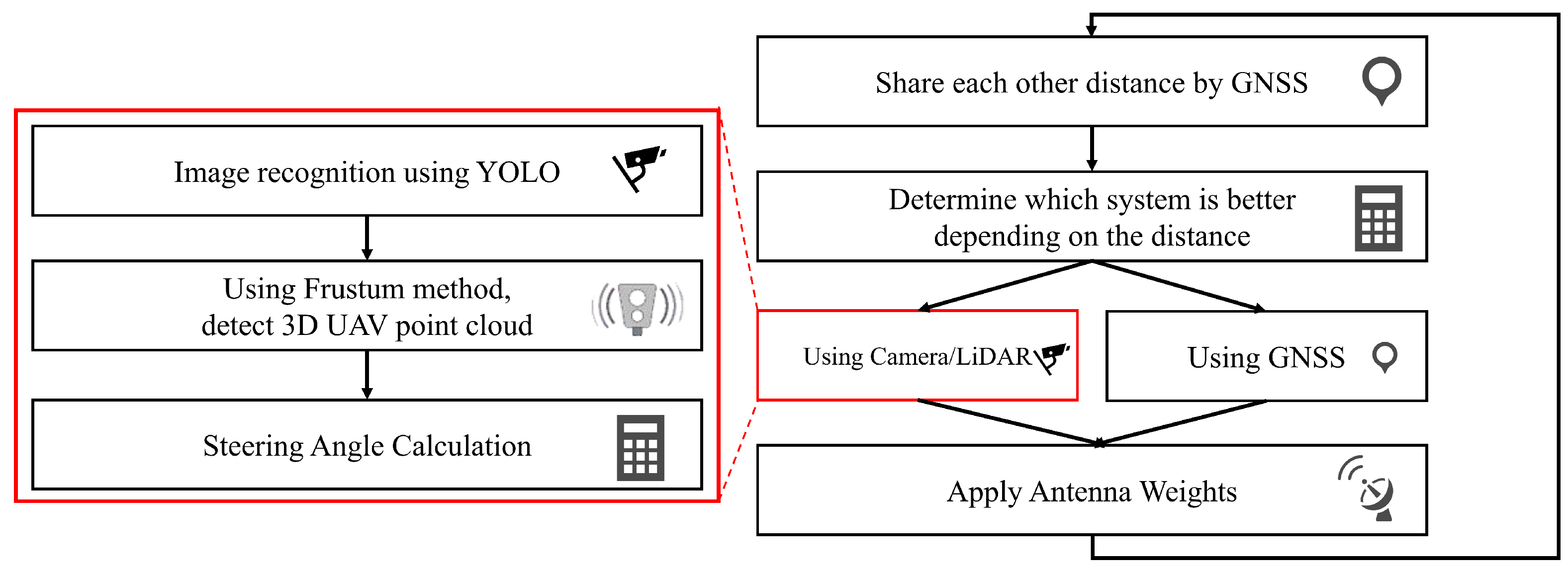
Figure 1. Diagram of proposed system model.
Futureinternet 17 00521 g001
Figure 2. Frustum method (3D green box means detection bounding box).
Futureinternet 17 00521 g002
Figure 3. Image recognition (green box means YOLO detection).
Futureinternet 17 00521 g003
Figure 4. Diagram of hybrid system model.
Futureinternet 17 00521 g004
Figure 5. Relationship between Distance and Detection Accuracy.
Futureinternet 17 00521 g005
Figure 6. Throughput vs. Distance for the Camera/LiDAR and GNSS Methods at Various Antenna Gains.
Futureinternet 17 00521 g006
Figure 7. Antenna Gain vs. Crossover Distance.
Futureinternet 17 00521 g007
Figure 8. Simulation Environment.
Futureinternet 17 00521 g008
Figure 9. Image from Ego UAV (Scenario 1 (<10 m): Short-Range Scenario to Evaluate Sensor Fusion Performance). The solid arrows indicates the LOS case, and the dashed arrows indicates the NLOS case.
Futureinternet 17 00521 g009
Figure 10. 3D Trajectory (Scenario 1 (<10 m): Short-Range Scenario to Evaluate Sensor Fusion Performance).
Futureinternet 17 00521 g010
Figure 11. Image from Ego UAV (Scenario 2 (<30 m): Transitional Scenario to Evaluate the Hybrid Approach). The solid arrows indicates the LOS case, and the dashed arrows indicates the NLOS case.
Futureinternet 17 00521 g011
Figure 12. 3D Trajectory (Scenario 2 (<30 m): Transitional Scenario to Evaluate the Hybrid Approach).
Futureinternet 17 00521 g012
Figure 13. Time series Angle Error (Scenario 1).
Futureinternet 17 00521 g013
Figure 14. CDF of Angle Error (Scenario 1).
Futureinternet 17 00521 g014
Figure 15. Time series Spectral Efficiency (Scenario 1).
Futureinternet 17 00521 g015
Figure 16. CDF of Spectral Efficiency (Scenario 1).
Futureinternet 17 00521 g016
Figure 17. Time series Spectral Efficiency (Scenario 2).
Futureinternet 17 00521 g017
Figure 18. Time series Spectral Efficiency with hybrid approach (Scenario 2).
Futureinternet 17 00521 g018
Figure 19. Hybrid approach depending on the distance.
Futureinternet 17 00521 g019
Figure 20. CDF of Spectral Efficiency with hybrid approach (Scenario 2).
Futureinternet 17 00521 g020
Figure 21. Scenario 1 in rain.
Futureinternet 17 00521 g021
Figure 22. Spectral Efficiency with hybrid approach (Scenario 1 in rain).
Futureinternet 17 00521 g022
Figure 23. CDF of Spectral Efficiency with hybrid approach (Scenario 1 in rain).
Futureinternet 17 00521 g023
Table 1. Communication & Propagation Model Parameters.
CategoryParameterValue
RF ParametersFrequency60 GHz
Bandwidth300 MHz
Transmit Power20 dBm
Antenna ParametersAntenna16 × 16 URA
Element Spacing0.5 λ
Antenna Gain25.9 dBi
HPBW 6 . 36
Table 2. Confusion Matrix: LiDAR-only vs. Camera/LiDAR .
MethodActual UAVActual Non-UAVTotal (Detections)
Detected
(predicted as UAV)
LiDAR-only970 (TP *)541 (FP)1511
Camera/LiDAR909 (TP)22 (FP)931
Not DetectedLiDAR-only641 (FN)
Camera/LiDAR547 (FN)
Total (Actual UAV)LiDAR/(Camera/LiDAR)1611/1456 (GT)
Note: Successful detection defined as error < 0.48 m (UAV size). * TP: True Positive, FP: False Positive, FN: False Negative, GT: Ground Truth.
Table 3. Detection Performance Metrics.
MethodRecall
(TP/GT)
Precision
(TP/Detections)
F1 Score
LiDAR-only method0.6020.6420.620
Camera/LiDAR method0.6240.9760.761
Table 4. Comparison of Results for Each Method (Scenario 1).
MethodAvg. Angel ErrorAvg. Spectral Efficiency
Camera/LiDAR8. 70 11.98 bits/s/Hz
GNSS-based 11 . 13 9.54 bits/s/Hz
Beam Sweep 22 . 21 10.52 bits/s/Hz
Ideal 13.66 bits/s/Hz
Omni 6.30 bits/s/Hz
Table 5. Comparison of Results for Each Method (Scenario 2).
MethodAvg. Spectral Efficiency
Hybrid10.71 bits/s/Hz
Camera/LiDAR9.87 bits/s/Hz
GNSS-based9.75 bits/s/Hz
Beam Sweep9.45 bits/s/Hz
Ideal12.71 bits/s/Hz
Omni5.00 bits/s/Hz
Table 6. Comparison of Results of Average Spectral Efficiency (Clear vs. Rain).
MethodAvg. Spectral Efficiency (Clear)Avg. Spectral Efficiency (Rain)
Camera/LiDAR11.98 bits/s/Hz11.58 bits/s/Hz
GNSS-based9.54 bits/s/Hz9.54 bits/s/Hz
Beam Sweep10.52 bits/s/Hz10.52 bits/s/Hz
Ideal13.66 bits/s/Hz13.66 bits/s/Hz
Omni6.30 bits/s/Hz6.30 bits/s/Hz
Table 7. Comparison of Results of 10-percentile value (Clear vs. Rain).
Method10-Percentile Value (Clear)10-Percentile Value (Rain)
Camera/LiDAR10.54 bits/s/Hz10.28 bits/s/Hz
GNSS-based3.40 bits/s/Hz3.40 bits/s/Hz
Beam Sweep8.55 bits/s/Hz8.55 bits/s/Hz
Ideal15.40 bits/s/Hz15.40 bits/s/Hz
Omni6.89 bits/s/Hz6.89 bits/s/Hz
Disclaimer/Publisher’s Note: The statements, opinions and data contained in all publications are solely those of the individual author(s) and contributor(s) and not of MDPI and/or the editor(s). MDPI and/or the editor(s) disclaim responsibility for any injury to people or property resulting from any ideas, methods, instructions or products referred to in the content.