Article

The Future of Flying Base Stations: Empirical and Numerical Investigations of mmWave-Enabled UAVs

1
Department of Electronic Engineering, Tokyo Institute of Technology, 2-12-1 Ookayama, Meguro-ku, Tokyo 152-8550, Japan
2
Department of Creative Informatics, The University of Tokyo, 7-3-1 Hongo, Bunkyo-ku, Tokyo 113-0033, Japan
*
Authors to whom correspondence should be addressed.
Future Internet 2024, 16(1), 5; https://doi.org/10.3390/fi16010005
Submission received: 20 October 2023 / Revised: 13 December 2023 / Accepted: 21 December 2023 / Published: 25 December 2023

Abstract

:
Nowadays, wireless communications are ubiquitously available. However, as pervasive as this technology is, there are distinct situations, such as during substantial public events, catastrophic disasters, or unexpected malfunctions of base stations (BSs), where the reliability of these communications might be jeopardized. Such scenarios highlight the vulnerabilities inherent in our current infrastructure. As a result, there is growing interest in establishing temporary networks that offer high-capacity communications and can adaptively shift service locations. To address this gap, this paper investigates the promising avenue of merging two powerful technologies: Unmanned Aerial Vehicles (UAVs) and millimeter-wave (mmWave) transmissions. UAVs, with their ability to be operated remotely and to take flight without being constrained by terrestrial limitations, present a compelling case for being the cellular BSs of the future. When integrated with the high-speed data transfer capabilities of mmWave technology, the potential is boundless. We embark on a hands-on approach to provide a tangible foundation for our hypothesis. We carry out comprehensive experiments using an actual UAV equipped with an mmWave device. Our main objective is to meticulously study its radio wave propagation attributes when the UAVs are in flight mode. The insights gleaned from this hands-on experimentation are profound. We contrast our experimental findings with a rigorous numerical analysis to refine our understanding. This comparative study aimed to shed light on the intricacies of wave propagation behaviors within the vast expanse of the atmosphere.

1. Introduction

In recent years, the explosive growth of various applications, such as video streaming services, has caused total mobile network traffic to increase at an average annual rate of 46% [1]. Even in Japan, in June 2023, the average traffic per contract increased approximately 1.6 times in three years and 1.2 times in one year [2]. Fifth generation mobile communication system (5G) services were launched worldwide in 2019 to address this issue [3]. In the 5G era, people and objects are connected to the Internet as social infrastructure. This trend is expected to continue in the future, and in the Beyond 5G/6G era, mobile communication systems are expected to function as the basic infrastructure of society [4,5,6,7]. In today’s society, it is clear that telecommunications are an indispensable technology for daily life. The number of subscriptions to mobile communications in Japan, including cell phones that we carry with us and use all the time, was approximately 205.48 million at the end of September 2022, an increase of 3.5% from the previous year [8]. In addition, the number of mobile applications is expected to increase, as mobile telecommunications are essential in increasingly active fields such as the Internet of Things (IoT) for home appliances and self-driving cars [9,10,11]. Since 2019, 5G, which was anticipated as a foundational framework for connecting the IoT, has been launched globally [12]. Notably, the adoption of millimeter waves (mmWaves), which offer a broader bandwidth for enhanced throughput, marked the first in mobile communications to address the swiftly rising user traffic [13]. It is clear from this that, increasingly, the amount of data generated by mobile communications will further increase. In addition, Industry 5.0 has recently been envisioned by the European Commission as a roadmap for the future, aiming to foster a prosperous society through the strategic use of advanced technologies such as artificial intelligence, robotics, big data, and the IoT [14]. These technologies are being put to practical use in digital twins that connect the real and virtual worlds [15]. Unmanned Aerial Vehicles (UAVs), which can move freely in three dimensions, are essential to realizing Industry 5.0 [16,17]. UAVs have recently been widely used in military and civilian applications, characterized by their high mobility, rapid deployment, and low cost. Examples of use include reconnaissance, transportation, inspection, agricultural irrigation, disaster relief, and many other fields [18,19,20,21,22].
While high-quality communications are available to everyone, there are situations in which communications become unavailable. This is the case during major disasters and large-scale events: the magnitude 6.5 Kumamoto earthquake in April 2016 caused landslides and commercial power outages that knocked out as many as 400 cell phone base stations (BSs), rendering cell phones temporarily unusable [23]. In addition to earthquakes, there have been many cases overseas where communications have been disrupted due to hardware damage caused by hurricanes [24,25]. Since communication is necessary for rescue operations during a disaster, restoring the communication environment quickly is essential [26,27,28]. During large-scale events, the number of accesses and the amount of traffic in a local area will increase due to the active posting of videos and photos due to the spread of social networking services (SNSs), creating a situation where sufficient communication is impossible [29]. Adding more BSs to cope with these temporary situations is costly for installation and maintenance. In addition, since mobile base station vehicles are affected by the ground environment, such as going to the site to install them for communication area restoration, it is difficult to respond quickly in the event of road damage [30]. Therefore, a temporary network is needed that can provide high-capacity communications and flexibly change the location of its provision. Therefore, network construction using mmWave frequency band radio waves and UAV base stations is expected.
We will use UAV BSs that utilize mmWave band radio waves to address these issues. mmWave radio waves are in the 30–300 GHz band, a high-frequency band characterized by high-capacity, low-latency communications [31]. In addition, drones are not dependent on the ground environment, such as traffic conditions, and can be deployed remotely and unmanned. The mmWave bandwidth has the disadvantages of being vulnerable to obstacles and being affected by distance attenuation [32]. UAV technology enables communications from the sky, which provides a clear line of sight, and beamforming technology enables high-quality communications.
The system architecture of a mmWave UAV BS is shown in Figure 1 [33]. Here, we consider a situation where the existing cellular communication network is no longer available. The entire system is divided into two parts: backhaul UAVs and access link UAVs. The backhaul UAVs connect the access link UAVs with available ground BSs far from the user. By deploying an appropriate location and number of backhaul UAVs, multi-hop communication is possible even when the distance between the user and the ground BS is large. Access link UAVs communicate directly with users instead of BSs. mmWave bands are used for all radio communications between these backhaul UAVs and the access link UAVs. mmWave bands are highly linear and are significantly attenuated by obstacles. Since this architecture utilizes drones, it is possible to communicate in the upper airspace area with good communication visibility without being affected by obstructions. In addition, since there has been little use of communications in the sky area and mmWave band radio waves have not been used much, it is possible to communicate with little radio interference.
Currently, mobile BS vehicles are used for temporary network construction during emergencies, but drones can cover a wider area because they communicate from a higher altitude [34]. In the future, satellite communications such as “Starlink” and UAV-based communication technologies such as HAPS (High Altitude Platform Systems) are expected to be used for communications from the sky [33,35] at the altitude of about 20 km. On the other hand, the drones in this paper will be used at altitudes of tens to hundreds of meters so that the communication distance will be relatively short, the atmospheric loss will be smaller than others, and communication will be possible with low latency. In the past, network construction utilizing UAV BSs had been considered by other researchers, but only microwaves had been used to guarantee connectivity [36]. Microwaves have limited applicability due to bandwidth limitations. There is also concern about the depletion of frequency resources, necessitating new research on frequency sharing and the development of higher frequency bands. Although there have been studies on building UAV-based networks using mmWave technology, these have been limited to theoretical studies based on simulations [37,38].
The main features of 5G communication services include high-capacity communications, large numbers of simultaneous connections, low latency, and high reliability [39]. In [40], latency in mmWave networks was studied. The goal there was to construct an edge content delivery system that adapts to user information and relocate content servers through dynamic routing on a mmWave mesh backhaul network, and experiments were conducted to study its effectiveness. The latency in the paper was measured through ping tests.
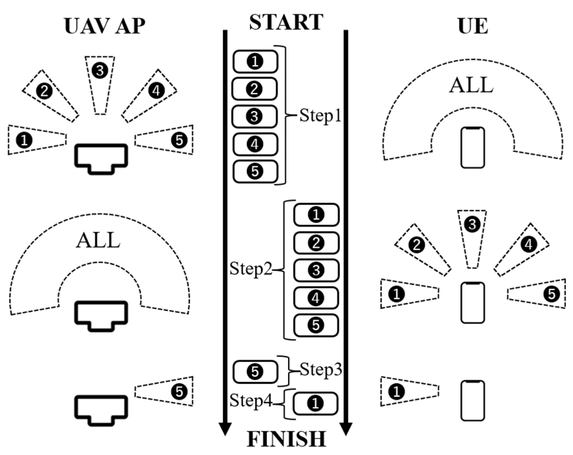
Since mmWave communications are significantly affected by distance attenuation and shielding, the placement of UAVs concerning user distribution is an important issue [33]. In [33], dynamic placement of access UAVs for mmWave UAV BSs for user distribution was considered. Here, assuming that the user distribution is known in advance, the authors proposed a method of UAV placement by frequency division to maximize the system rate. Here, the method in [41] was used to determine the optimal altitude of the UAVs, while the K-means method and the minimum circle problem were employed to determine the UAVs’ optimal interference-reduced placement. The paper also showed that frequency division efficiently distributes the available bandwidth to each UAV, which helps to avoid interference and improves the overall system rate.
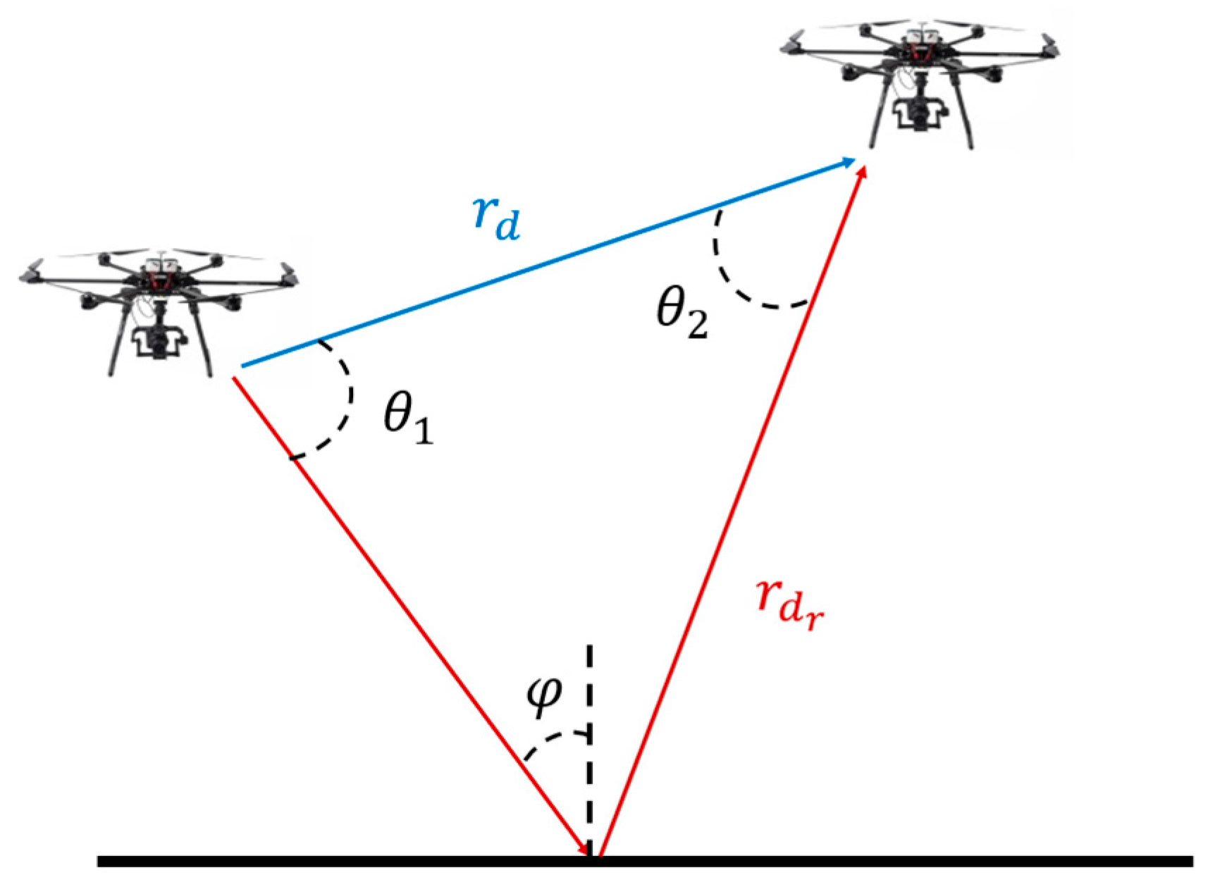
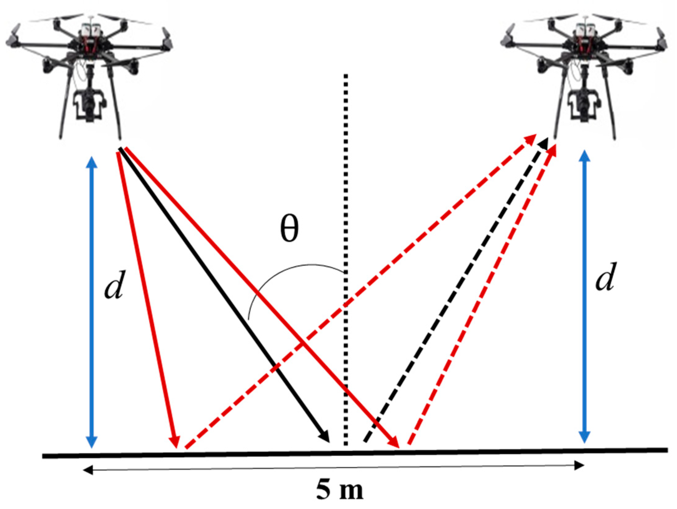
In mmWave UAV BSs, many UAVs communicate with each other, but the communication from the UAVs to the user is directed toward the ground, which causes ground reflection. Therefore, to realize a simultaneous uplink/downlink UAV network, it is necessary to consider ground-reflected wave interference between adjacent UAVs. For this purpose [42], employed SIR (Signal Interference Power Ration) as a metric to show that an architecture with circularly polarized antennas can significantly reduce interference compared to the conventional architecture with linearly polarized antennas. Furthermore, it was found that interference can be significantly reduced when both backhaul UAVs and access UAVs use identical circularly polarized antennas.
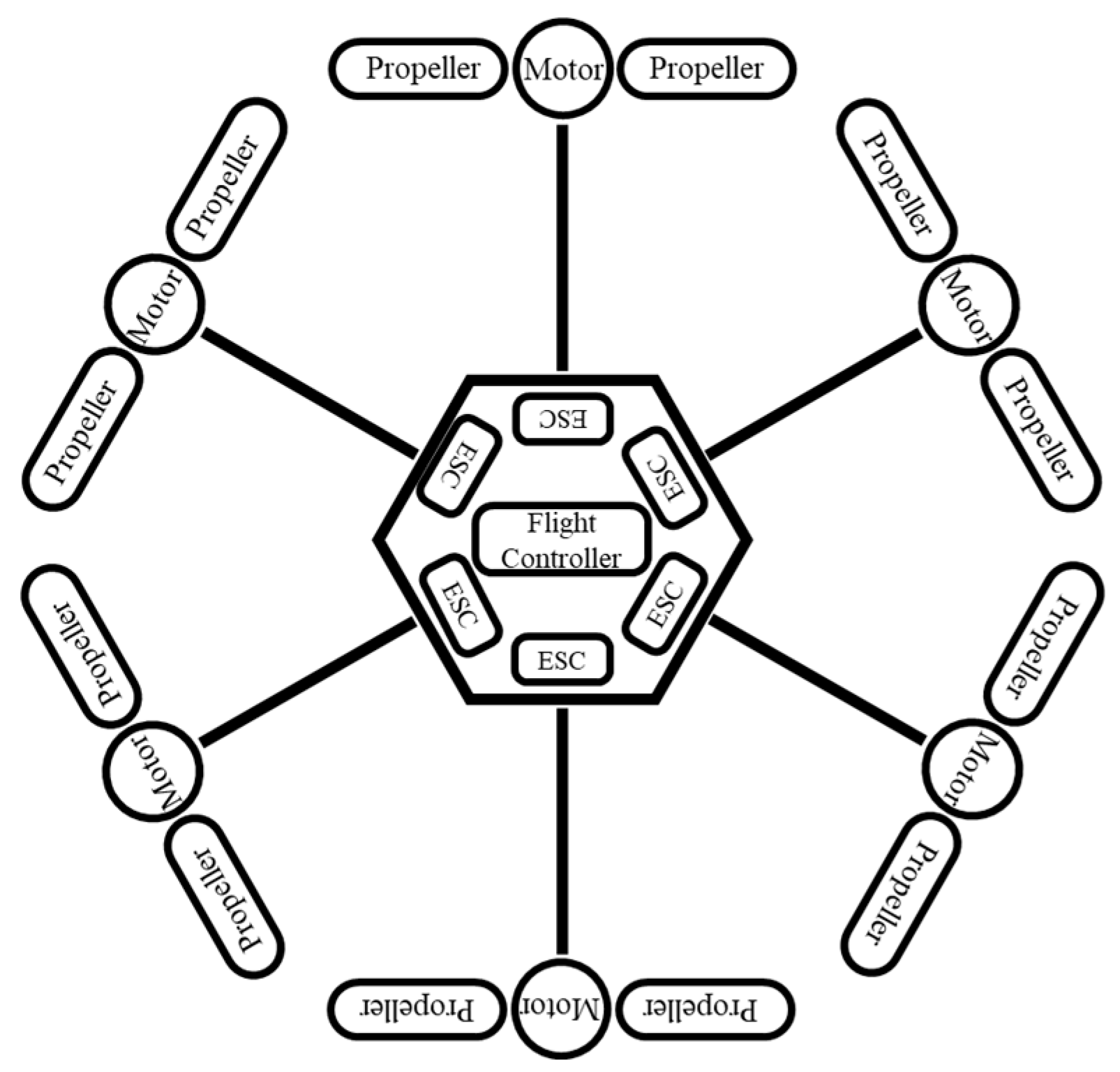
In addition to the above, power consumption is also an issue in mmWave UAV BS networks. Although specifications for wired drones have been considered, the operating range of UAVs is limited by the power cable length [43,44]. To take full advantage of the freedom of movement that is also an advantage of UAVs, this study focuses on UAVs that can operate wirelessly without earth connection cables. Therefore, each UAV must be equipped with a battery. This battery must power not only the UAV’s flight but also the communications of various wireless interfaces. There is a tradeoff: increasing battery capacity increases the relative weight of the UAV while also increases the power supplied to the UAV. However, the issue of UAVs’ power consumption is beyond the scope of this paper, knowing that there is research and development of lightweight, low-power wireless components and lightweight, high-capacity batteries, or even wireless power transmission for UAVs.
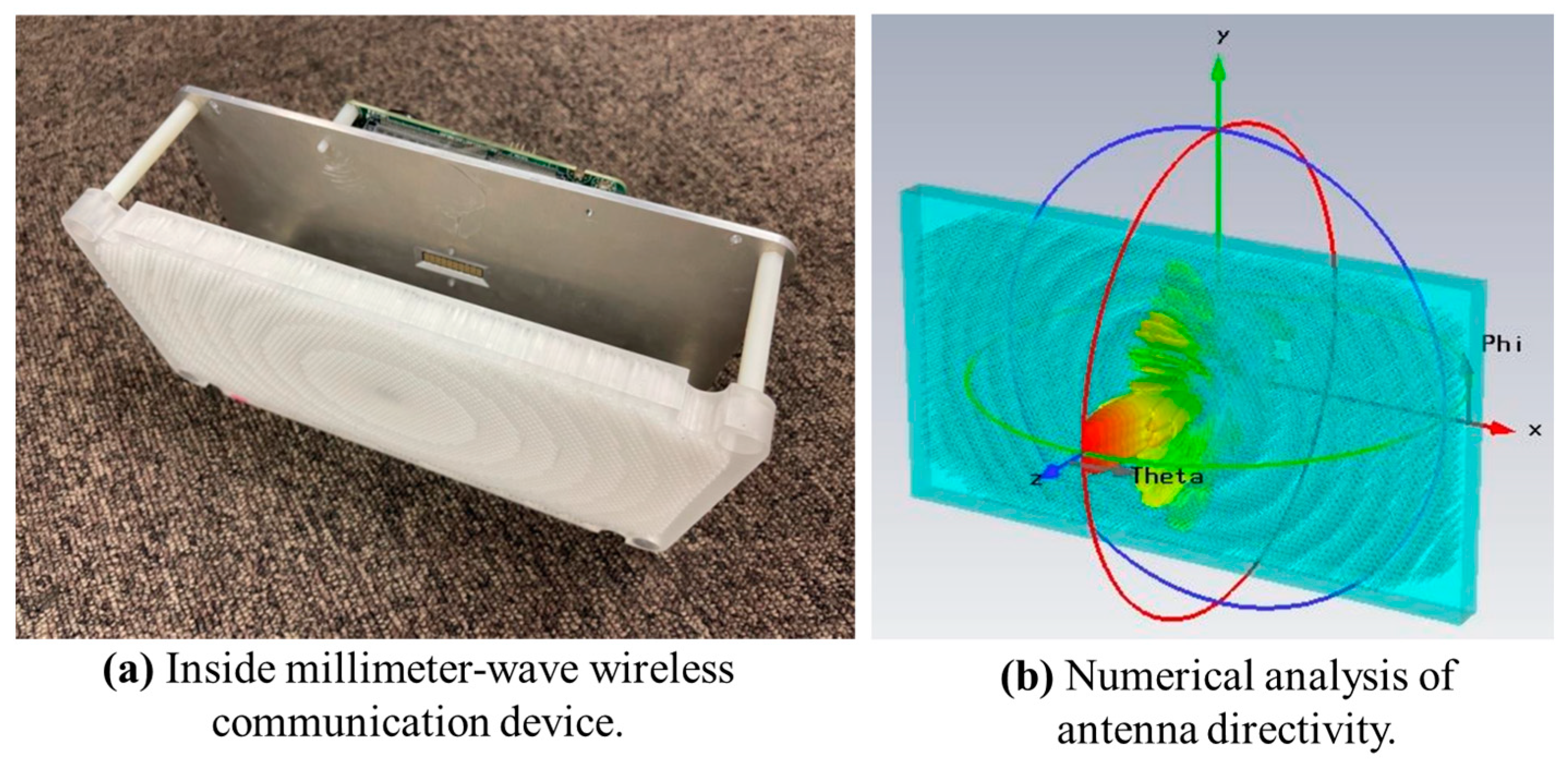
Wireless communications at the mmWave frequency band are critical for 5G wireless networks [45]. In addition, understanding radio propagation characteristics in the airspace domain is essential for the efficient use and development of air-to-ground mobile communication systems in the future. However, to the authors’ best knowledge, there are only a few studies focusing on the use of the mmWave frequency band for low-altitude platforms such as UAVs [37].
Therefore, this paper examines the construction of a UAV BS network using mmWave frequencies and demonstrates its effectiveness via both empirical experiments and validating theoretical studies. The major contributions are briefly outlined below.
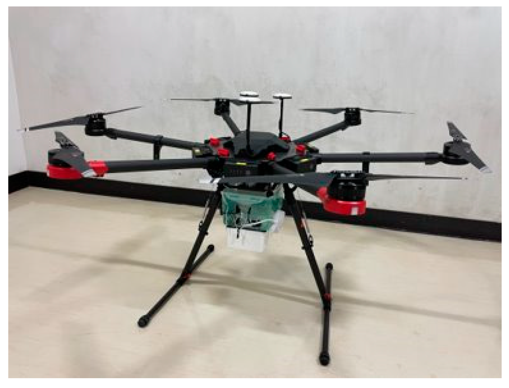
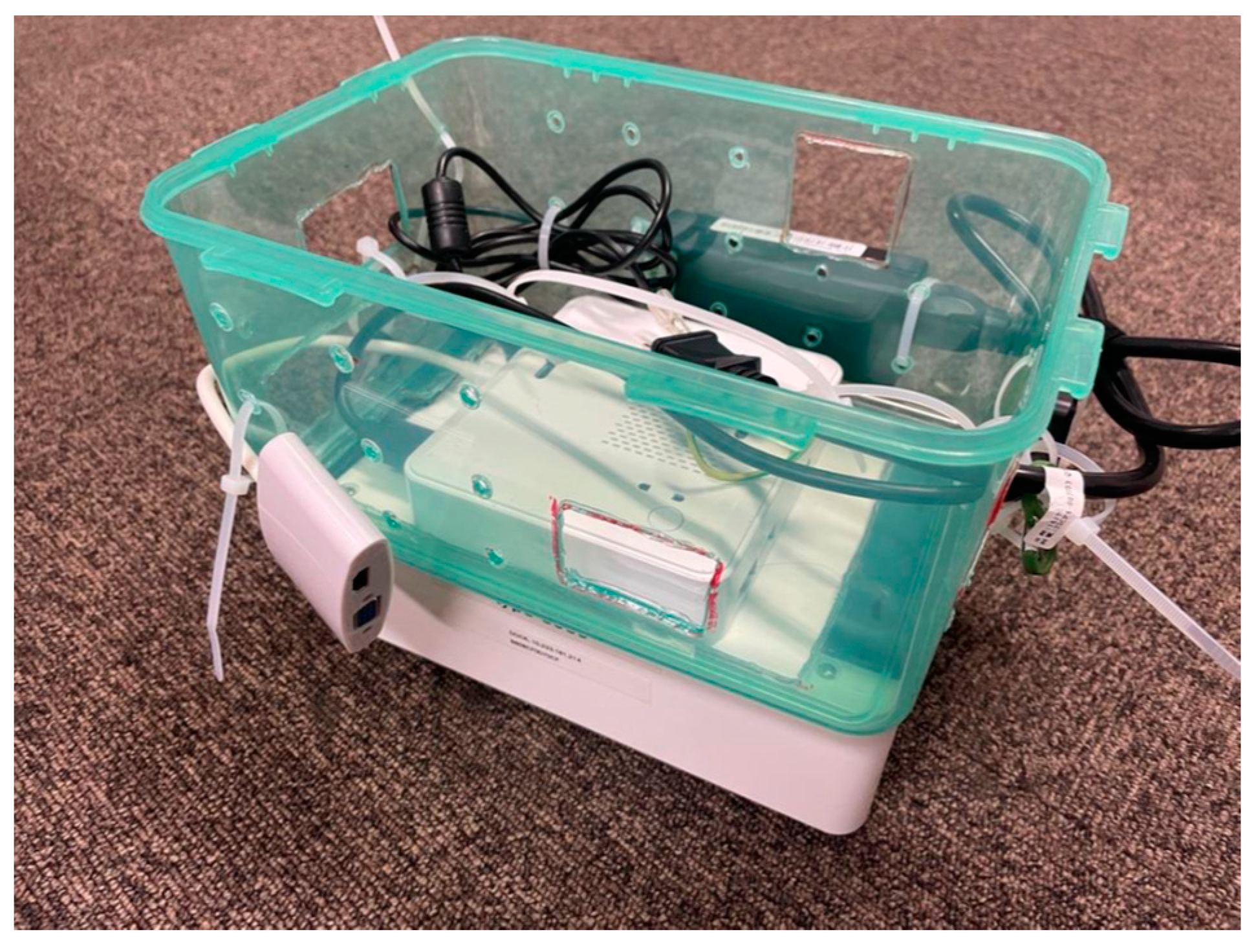
  • We are the first to propose, design, and implement a UAV system equipped with a mmWave device.
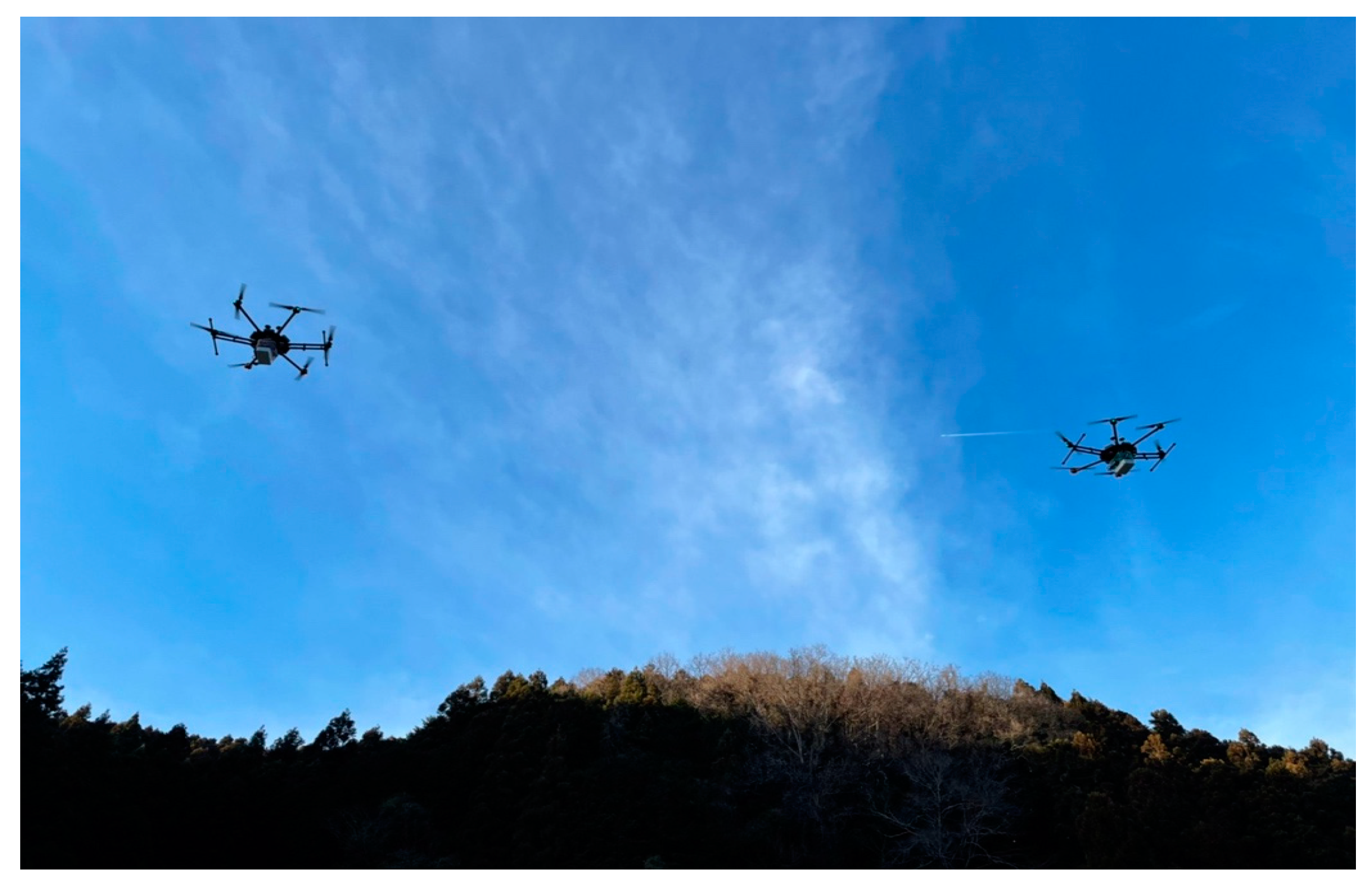
  • We conducted an outdoor proof-of-concept (PoC) experiment with multiple drones equipped with mmWave communication devices, evaluating the proposed system over various scenarios.
  • We discussed the radio propagation model for mmWave communications between UAVs, based on the data collected. The validity of the proposed model is demonstrated by comparing the outdoor experimental results with those from theoretical studies.
The structure of this paper is presented as follows. Section 2 provides detailed technical descriptions and relevant prior studies. This section begins by examining mmWave wireless communication, followed by a discussion on the dynamic deployment approach for mmWave UAV access, and concludes with an exposition on mmWave antenna polarization. Section 3 presents an in-depth look at our proposed mmWave-powered UAV system, describing the experimental methods and presenting the results. Section 4 describes the numerical evaluation model, including the setup and the resulting numerical data. Section 5 compares the experiment and numerical results. Finally, Section 6 concludes the paper with a summary and discussion of future work.
This paper is an extended version of a conference paper presented at The 14th International Conference on Ubiquitous and Future Networks (ICUFN 2024) held in Paris, France in July 2023 [46].

2. Technical Background

This section presents technical descriptions that appear in this paper. Section 2.1 introduces millimeter-wave band communication technology; Section 2.2 introduces UAV technology.

2.1. Millimeter-Wave Wireless Communication Technology

mmWave operates within the frequency range of 30 to 300 GHz [47]. These waves are a high-frequency band offering wide bandwidth, facilitating high-speed and high-capacity communications. Additionally, since a wide bandwidth is allocated, it can accommodate more terminals or higher traffic volumes [10]. However, a notable drawback is their sensitivity to interference from rain, fog, and other obstacles, resulting in significant distance attenuation [11]. While 5G currently operates Frequency Range 2 (FR2), such as 26.5–29.5 GHz (band n 257), which is categorized under submillimeter waves, this paper focuses on harnessing the 60 GHz band—a license-free spectrum that is ready for implementation [48,49].
The 60 GHz band was originally used for motion sensors and radar with high-precision positioning functions, and there are also data communication standards that utilize the 60 GHz band, such as IEEE802.11ad/ay [50,51,52]. Research is also being conducted on IEEE802.11ad communications utilizing the 60 GHz band for the introduction of 5G in urban areas [53]. In this paper, we utilize IEEE802.11ad communication standard devices for our experiments, which will be discussed in Section 3. The basic design of IEEE802.11ad is shown in Appendix A. IEEE802.11ad uses a directional communication method with beamforming to suppress attenuation and other drawbacks caused by high frequency bands [54]. IEEE802.11ad includes a function to adjust beamforming according to the procedure shown in Figure 2 [47]. This determines the beam direction and improves directivity as following steps.
  • The AP transmits a beacon signal, varying the beam direction. The UE receives this beacon signal using semi-omni-directivity.
  • The operations of Step 1 are repeated, but with the transmitter and receiver exchange their roles.
In Steps 3 and 4, the communication between the AP and UE is established using the directivities determined, respectively, in Steps 1 and 2, which maximizes the expected received signal strength.

2.2. UAV Classification, Configuration, and Advancement in Flight Technology

UAVs can be broadly classified into two types: multi-copter types, such as drones, and fixed-wing types, such as airplanes [55]. The differences between the two types are shown in Table 1. UAVs are widely used in military and civilian fields due to their high mobility, rapid deployment, and low cost [56,57]. Examples of use include reconnaissance, transportation, inspection, agricultural irrigation, disaster relief, and many other fields. This paper assumes using a multi-copter type with excellent maneuverability and hovering performance. The configuration of a typical multi-copter UAV is shown in the Figure 3. The flight controller sends commands to each Electric Speed Controller (ESC) according to the instructions from the transmitter [58]. In addition, during flight, the position information, altitude information, etc., obtained from the air pressure sensor, acceleration sensor, GPS, etc., are transmitted to the transmitter. At the same time, the flight controller continues to send commands to each ESC to maintain stable expectations in the face of environmental changes. Currently, it is possible to set the flight path in advance and have the flight controller operate the planned path by itself, and there are also UAVs with built-in collision avoidance systems. The transmitter is equipped with levers, switches, and other interfaces necessary for control, and it communicates wirelessly with the aircraft. Microwaves are generally used for this communication. A battery powers the aircraft. To lengthen the flight time, the battery capacity must be increased, but there is a tradeoff in that the weight increases, resulting in higher power consumption. In the future, UAVs are expected to have longer flight times by using higher power efficiency, lightweight high-capacity batteries, and even concurrent wireless power transfer technology [43,59].

3. Field Experiments

This section will explain our developed PoC system, demonstration experiments, and the corresponding measurement results. The distance and coverage characteristics of millimeter-wave communications between the access UAV and the terminal and the presence of ground reflected wave interference will be investigated.

3.1. Experiment Environment

The experimental field was at Ogawa-cho, Hiki-gun, Saitama, Japan. The experimental field is shown in Figure 4. This rural area with little pedestrian traffic was selected for safe flights. Professional pilots were hired to manage and operate the UAVs in the demonstration experiment. Due to the limitation of our developed hardware, only throughput was measured in the experiments to evaluate the communication quality.
Table 2 shows the mmWave devices’ specifications used in our demonstration experiments. In addition, a photograph of the inside of the mmWave device and numerically analyzed antenna details are shown in Figure 5. The reasons for selecting this device were that it is small and lightweight enough to be mounted on a UAV and is capable of 100 m communications. The device comprises a small PC, an array, and a lens antenna [47]. The mmWave wireless communication device was equipped with Ubuntu, and throughputs were measured using the iperf3 command. The measured values were evaluated at MAC layer.
The demonstration experiment used two “Matrice 600 Pro” UAVs manufactured by DJI. They can carry a maximum of 6 kg of load, and their specifications are shown in Table 3 [60]. The screen on the transmitter side of the drone displays a map and air information such as the drone’s position, altitude, and remaining battery power. The flight time of the UAV used in the experiment was about 20 min per flight, prioritizing safety. Therefore, it was only possible to acquire experimental data for limited scenarios.
The UAV equipped with mmWave interfaces and the on-board mmWave extension equipment are shown in Figure 6 and Figure 7, respectively. Another item was used in the experiment. Others used are shown in Table 4. A large pocket warmer was inserted to keep the temperature at about 20 °C to prevent the battery from deteriorating in performance.

3.2. Experimental Results

In wireless communications, distance attenuation is unavoidable. In addition, mmWave communications are more strongly affected by distance attenuation than microwaves. As for the system design of access UAVs, the placement and other factors will vary greatly depending on how much coverage can be secured. In addition, if the number of UEs on the ground is large, multiple access UAVs are assumed to work near each other. However, since both will be communicating toward their associated ground terminals, earth-reflected wave interference will be an issue.
Using the above equipment, three types of experiments were conducted in this paper to determine the distance and coverage characteristics and the extent to which earth-reflected wave interference occurs:
  • Direct Experiment
This experiment examined changes in throughput by varying the height of the UAV against the fixed ground user.
  • Coverage Measurement
This experiment varied the ground user’s location against a UAV BS hovering at a certain height to measure its coverage.
  • Ground Reflection Experiment
When there are two UAV BSs, this experiment investigated how much ground reflection affects the communications.
Details about each experiment are explained as follows.

3.2.1. Direct Experiment

A schematic diagram of the experiment is depicted in Figure 8a. The relationship between UAV–UE vertical distance and throughput was investigated. Throughput measurements were taken by increasing the altitude of the UAV by each 5 m step. The measurement results are shown by the green circle in Figure 9. The maximum physical layer throughput of the antenna device is 4.62 Gbps. However, the measurement results in this study are not throughputs of the physical layer but those measured at the MAC-SAP (that corresponds to the MAC layer throughput). It can be observed from the Figure 9 that a saturated throughput of approximately 1.4 to 1.5 Gbps is achieved up to an altitude of about 40 m. The quality deteriorated after 45 m due to distance attenuation, resulting in lower throughput.

3.2.2. Coverage Measurement

A schematic diagram of the experiment is shown in Figure 8b. Coverage was measured by varying the position of the ground user against a fixed-height UAV. This time, the altitude of the UAV was set at 30 m, and the UE’s locations were set apart by 2.5 m steps from the center beneath the UAV. The green circles depicted in Figure 10 show the measurement results.
The results show that the attenuation increases at a horizontal distance of 10 m. Since the physical length of the communication link is about 32 m when the horizontal distance is 10 m, it can be understood that the deterioration of communication quality is not due to distance attenuation but to the deterioration of antenna directivity due to the increase in the incident angle.

3.2.3. Ground Reflection Experiment

A schematic diagram of the experiment is shown in Figure 8c. The experiment was to observe how ground reflections affect the communications of UAV BSs under conditions of two closely located UAVs. In this experiment, one of the UAVs worked as a BS while the other played the role of a UE. Here, the interference was evaluated by the quality of the indirect communication link via the ground reflection path between the two hovering UAVs. In other words, the higher the throughput, the stronger the signal arrives at the other UAV via the reflected path. In the measurements, the horizontal distance between the UAVs was set to 5 m, and the throughputs were measured when both UAVs gradually increased their altitudes. The snapshot of the experiment can be seen in Figure 11. The measurement results are shown by the green circle in Figure 12.
Several findings can be seen from these results. When the drone’s altitude is low, that makes a large incident angle of the reflected path, and the throughput is poor since the ground-reflection path is out of the main lobe of the directivity antenna. When the altitude is high enough, the incident angle is smaller such that the ground-reflection path is within the main lobe of the directivity antenna, and we can observe improved communication quality (or worse interference conditions). Furthermore, increasing the altitude, the throughput decreases naturally due to longer distance attenuation.

4. Numerical Evaluations

To further understand our experimental results, the radio propagation characteristics between an access UAV and a terminal using the mmWave band are investigated via numerical evaluations in a virtual environment imitating the experimental one. In wireless communications, propagation attenuation due to distance and coverage effects due to antenna directivity is essential for the link budget. That is why optimizing the position (altitude and horizontal location) of access UAVs is required, and it is important to understand the distance and coverage characteristics of our access UAVs. Furthermore, it is also significant to understand how inter-system interference via ground reflection affects our system performance in scenarios with multiple UAVs. Hence, distance characteristics, coverage characteristics, and ground-reflected wave characteristics will be numerically investigated in this section to supplement our experimental results.

4.1. Numerical Evaluation Model

In the numerical evaluation, we consider radio propagation in free space. The received power is calculated using the Frith transfer formula in Equation (1), where P r is the received power, λ is wavelength, P t is the transmitted power, G r is the receive antenna gain, and G t is the transmit antenna gain [61].
P r   [ d B ] = 20 log λ 4 π d + G t + G r + P t L o x
This paper considers the usage of a 60 GHz mmWave band, which is particularly affected by atmospheric attenuation [62]. Therefore, atmospheric attenuation L o x is considered in the above model. For the antenna gain, the antenna model in Equation (2) is employed, where θ 3 d B is the half beamwidth [63].
G θ = 10 G 0 3.012 2 θ θ 3 d B 2     ( θ     | θ m l 2 | ) 10 0.41 ln θ 3 d B 10.6     ( o t h e r )
In addition, θ m l and G 0 are obtained using the following equations.
θ m l = 2.58 θ 3 d B
G 0 [ d B ] = 20   log 10 1.62 sin π 180 θ 3 d B 2
An example of this antenna gain model is shown in Figure 13. When considering ground reflection, the two-ray model in Equation (5) is adopted [64].
P r = 10 log P t G t 0 G r 0 λ 4 π r d + G t θ 1 G r θ 2 + λ 4 π r d r Γ e j 2 π λ r d r d r 2 L o x
The reflection coefficient Γ is shown in Equation (6) [65].
Γ = n 2 c o s φ n 2 sin 2 φ n 2 c o s φ + n 2 sin 2 φ
where φ is the angle of incidence of the ground-reflected wave with respect to the ground, as shown in Figure 14. Also, n is dependent on the ground material and is shown in Equation (7) [66].
n = ε r j σ 2 π f ε 0
where ε r is dielectric constant, ε 0 is dielectric constant of vacuum, f is radio frequency, σ is conductivity. The Signal to Noise Ratio (SNR) [65] is computed using Equation (8). P n is the thermal noise power provided by Equation (9).
S N R = P r P n
P n   [ d B ] = 10   log 10 k q K B + N F
where B is bandwidth, k q is Boltzmann’s constant, K is temperature in Kelvin, and NF is Noise figure. The throughput is calculated using Shannon’s famous capacity equation, where C 0 is the maximum performance value defined by the used hardware [67].
C = B l o g 2 ( 1 + S N R )
T = m i n ( C 0 , C )
The actual throughput in the measurements will be degraded due to many factors and the above theoretical throughput would only indicate the upper bound.

4.2. Numerical Evaluation Parameters

The list of parameters used in the numerical evaluation is shown in Table 5, which are compatible with the IEEE802.11ad standard also used in our demonstration experiments. The transmit spectrum conforms to the spectrum mask shown in Figure 15 [68]. The bandwidth is 2.16 GHz, but whole band cannot be used for communication because of the guard bands. In this paper, 1.88 GHz is considered the effective bandwidth [68]. Based on the antenna model in [63], as the peak of the antenna gain is 25.4 dBi, we found that the antenna 3 dB beam width corresponds to 9.98 deg. Numerical evaluations were performed by assuming that perfect beam alignments were operated on both sides of the transmitter and the receiver. For comparison, we also performed theoretical numerical evaluations with antenna gains of 15, 20, and 30 dBi. The corresponding 3 dB beam widths are 33.47 deg, 18.65 deg, and 5.87 deg, respectively.

4.3. Numerical Results

4.3.1. Direct Experiment

Distance attenuation characteristics are investigated where the upward-facing antenna is fixed to the ground and the UAV, which has a downward-facing antenna installed as an access point, is gradually raised to a higher altitude directly above the ground. Similar to our experimental results, the achievable throughput is used as a metric to indirectly evaluate radio propagation characteristics. In this case, it is assumed that the antenna on the ground does not receive ground-reflected waves since it is at an altitude of 0 m, and only the Line of Sight (LOS) path from the access UAV is received. In addition, both the access UAV and the ground terminal’s antenna gains are assumed to be the same. The numerical results are shown in Figure 16. It can be seen that a saturated throughput can be achieved up to a certain height (distance between the transceivers) and then decays gradually due to propagation attenuation. It can also be found that the higher the antenna gain is, the higher the quality of communication can be ensured.

4.3.2. Coverage Measurement

Coverage characteristics are investigated where we assume that an access UAV with a downward-facing antenna is hovering at a fixed altitude and a ground user terminal with an upward-facing antenna gradually changes its horizontal distance. Similar to Section 4.3.1, it is assumed that the antenna on the ground does not receive ground-reflected waves since it is located at an altitude of 0 m, and only the LOS path from the access UAV is received. Figure 17 shows the numerical evaluation at different UAV altitudes of 10 m, 30 m, and 50 m with varying horizontal distances. In Figure 17b, the numerical results show that even at a close horizontal distance of 10 m, the performance degrades significantly. It means that the degradation is not due to distance attenuation but instead due to the fact that the angle of incidence did not face the main lobes of the antennas, which deteriorates the effective antenna gains. In addition, those with higher antenna gain (or narrower beam width) are revealed to be more susceptible to the angular shift. Hence, the steepness of throughput deterioration against the saturated rate is more remarkable for those with narrower beam widths. Our analyses at different UAV altitudes also reveal that the higher the UAV is, the longer the coverage distance (that can achieve the saturated rate) that can be realized. On the other hand, since propagation attenuation increases against longer distances, it is clear that higher antenna gain is effective to maintain better communication quality (higher throughput) when evaluated at the same distance.

4.3.3. Ground Reflection Experiment

The earth-reflected waves will be investigated in this section. The throughput between two UAVs with downward-facing antennas, each of which plays the role of transmitter and receiver, respectively, is indirectly used to investigate the propagation characteristics of the earth-reflected radio waves. The two UAVs are kept at the same altitude. In contrast, this altitude is gradually increased, knowing that the relative locations of the two UAVs on the horizontal plane are fixed similarly to the experiment. Since there is no terminal on the ground at this time, the UAVs communicate with each other via ground-reflected waves, which means that the larger the throughput, the greater the interference effect of ground-reflected waves. The two antennas on the UAVs are considered to have the same antenna gain. Numerical evaluations were performed at different horizontal-plane separation distances of 5 m, 10 m, and 30 m, and the results are shown in Figure 18, separately. When the altitude is low, the antenna directivity deteriorates due to a broad incident angle, resulting in almost no throughput. The antenna’s directivity at higher altitudes improves owing to a steeper incident angle, resulting in higher throughput. On the other hand, throughput is decreased again at further higher altitudes due to the effect of distance attenuation. The attenuation is even higher than that in the direct experiment in Section 4.3.1 because the two UAVs are simultaneously flying at the same altitude, which doubles the traveling distance of the communication link. Also, when increasing the horizontal distance between the two UAVs and the antenna directivity deteriorates, the throughput performance decreases when evaluating it at the same UAV altitude. Therefore, the ground-reflected wave interference might be ignored in realistic scenarios with sufficient horizontal separation between the two UAVs.

5. Comparison of Experimental and Numerical Results and Discussions

Our observations in Section 3 and Section 4 show that while the distributions of the measurement and numerical results are analogous, there is a notable difference in their absolute values. Specifically, the measured saturation throughput in the experiments ranges from 1.4 to 1.5 Gbps, whereas the theoretical analyses project values around 4.5 to 4.6 Gbps. This discrepancy was due to many factors but the main reason is that the theoretical throughput is computed at the PHY layer while the hardware’s output throughput was evaluated at the MAC layer. At the same time, our numerical analyses target the PHY layer throughput using Shannon’s formula as a basis. Factors like the beam alignment process and the limitations of available modulation and coding schemes introduce uncertainties that theoretically make it challenging to gauge the interlayer’s inefficiency. Recognizing this complexity, we have chosen an empirical methodology in this study to bridge the gap between the experimentally measured and theoretically computed saturation rates.
T ~ = α × m i n ( C 0 , C )
In other words, the numerical throughput is scaled by a factor of α, which is a spectral efficiency coefficient that is responsible for all protocol-dependent loss (e.g., MAC portion over the whole physical frame, bandwidth, and time usage efficiency, etc.). In this paper, α is estimated from the difference between the saturated throughput of the experiment and theoretical results. The result was α = 1 / 3.2636 . After this modification, the results of experimental and numerical analyses are redrawn and depicted on a same graph again for comparison and discussion in the following sections.

5.1. Direct Experiment and Coverage Measurement

The results of the direct experiment are shown in Figure 19. The graphs show that both the measured and simulated throughputs are saturated up to 45 m, after which they decay. The difference between the measured and simulated values after the saturated throughput is because the numerical evaluation shows a continuous throughput, but the actual throughput is discrete due to the selection of MCS and other factors. A summary of the coding rates, etc. for each MCS in IEEE802.11ad is shown in Appendix B. In addition, we believe that this is because the numerical evaluation was able to take modulation, etc. into account in the MCS in the saturated throughput state due to α in Equation (12), but not in the other MCS states.
A comparison of the numerical evaluation and empirical results of the coverage experiment is shown in Figure 20. There is a similar performance trend between the theoretical and experimental results, although there is a close agreement when the horizontal distance is short and a slight error when it is long. As in the previous case, here too, we believe that the difference between the measured and simulated values is due to the difference in MCS, which is different from the α at saturation. In addition, the distributions at saturated throughput in Figure 19 and Figure 20 are almost identical, indicating that the attenuation at saturation can be taken into account with α utilized in Equation (12). As the horizontal distance increases, the error is not only due to the choice of MCS, but in fact may be due to the position error caused by the wind of the UAV and the deterioration of antenna directivity due to its tilted angle. In addition, when the received power is high, a high MCS also results in a high throughput. Therefore, the throughput is close to the Shannon capacity at high MCS values. In this case, α is set at high MCS at saturation, which means that the simulated value is larger than the measured value, because when the attenuation is high and MCS is low, the α must be even smaller than the set value.
In addition, the drone’s position was affected by the pilot’s operation, wind, and GPS corrections. Therefore, positional error must be taken into account. The drone’s flight performance in this experiment had an error accuracy of ±1.5 m for horizontal distance and ±0.5 m for vertical distance [60]. Figure 21 and Figure 22 show the results of numerical analysis of the maximum and minimum throughput values when the drone is positioned within this error range in the direct experiment and coverage measurement. The solid line is the average value, and the dashed lines are the maximum and minimum values. From the numerical results of the direct experiment with positioning errors in Figure 21, it can be seen that the difference between the theoretical and numerical results is relatively large at lower altitudes due to the deteriorating antenna directivity when there are misalignments caused by positioning errors. It can also be seen that the maximum and minimum values gradually converge as the positioning error becomes relatively smaller at higher altitudes. Figure 22 shows the graph of coverage measurement considering the positioning error. When the horizontal distance is small, the effect of the positioning error is small because the altitude is 30 m, and both the maximum and minimum values show saturated throughput values. When the horizontal distance increases to some extent, the measured throughput was within the range of the maximum and minimum numerical throughput, which validated the fact that drone’s positioning errors contributed to the discrepancy of the measured throughput against the numerical one. Also, the gap between the maximum and minimum throughputs at longer horizontal distances can be explained by the antenna directivity’s improvement or degradation due to the corresponding positioning errors.

5.2. Ground Reflection Experiment

Measured and simulated ground-reflected waves are compared in Figure 23. In the numerical evaluations, a two-ray model is employed to account for ground reflection [66]. Since the ground where the demonstration experiment was conducted was grassy, the parameters were set assuming a wet ground [66]. The distribution of measured and simulated values is slightly different, but the distribution is the same: throughput increases up to a certain altitude and then decreases again due to larger distance attenuation. The difference between the measured and simulated values can be attributed to the different values of conductivity and dielectric constant due to differences in the ground environment, and the fact that the ground geometry is not ideal in the actual experiment. Furthermore, numerical evaluations were conducted with an antenna gain of 25.4 dBi and different ground materials to confirm the effect [66,69]. The results are shown in Figure 24. The ground parameters utilized in the numerical evaluation are in Table 6. The trend of the measured values did not exactly follow the specific material, even the conductor, metal. One of the main reasons for this discrepancy could be due to the influence of the ground geometry, which was not perfectly flat as assumed in the numerical analysis. The next section will investigate this issue via the introduction of scattering waves.
Consider ground reflection where the ground is rough and multiple waves arrive due to scattering, the received power in dB can be calculated with the following equation.
P r = 10 log P t G t 0 G r 0 × λ 4 π r d + G t 1 G r 1 × λ 4 π r d r × Γ 1 × e j 2 π λ r d r d r                                               + G t i G r i × λ 4 π r d r i × Γ i × e j 2 π λ r d d r i 2 L o x
Γ = Γ 0 e 4 π σ λ 2
where σ is the surface roughness (root mean square (RMS) square value), r d is the linear distance between drones, r d r is the minimum distance of ground reflected wave, d r i is the distance of scattering waves, Γ is the value of the reflection coefficient, and Γ 0 is the specular reflection at that point [70]. An image of the scattered wave arrival model for ground reflection is shown in Figure 25. We assume that the scattering waves fall to the ground and arrive randomly with a normal distribution against the center located at 2.5 m in between the two drones.
Figure 26 summarizes numerical data taken from 100,000 ground reflection positions of the scattering waves derived numerically using our Monte Carlo simulation. The red line is a normal distribution approximation of 100,000 data. Empirically, this approximated normal distribution has a mean value of 2.5007 m, a maximum value of 4.8346 m, a minimum value of 0.397 m, and a standard deviation of 0.5003 m.
Using the above scattering model, Figure 27 show the results after 1000 Monte Carlo simulations when the numbers of generated scattering waves are 1, 3, 5, and 10, separately. The solid line is the mean value, and the dashed lines are the lower and upper bounds defined by the standard deviation. The earth’s surface roughness (RMS value) at this time is set to 100 μm.
These additional Monte Carlo simulation results show that when there are 1 to 5 scattering waves, the theoretical results’ approximation range can cover the measurement results, except for the measured values at the UAV’s altitude of 60 m. The throughput measured at 60 m can be considered as an outlier because the linear distance of the ground-reflected wave is more than 120 m, and it is not easy to measure at a distance longer than 100 m using our dedicated hardware. It can also be observed that throughput slightly increases with higher numbers of scattering waves, which means the effect of ground-reflected interference is more remarkable when there are more scattering waves.
The surface roughness (RMS value) was set at 100 μm in the above analysis, but in order to check whether it was appropriate or not, we performed 1000 Monte Carlo simulations with a fixed number of scattering waves of 3, while the surface roughness’s values are changed to 10 μm, 50 μm, 500 μm, and 1000 μm, individually. The results are shown in Figure 28. The results show that the larger the surface roughness, the lower the throughput. This is due to Equation (14), in which a thicker surface roughness yields a smaller reflection coefficient. The results also imply that surface roughness plays an important role to understand scattering phenomenon of mmWaves.
Positioning errors in multiple arrival waves of ground reflection are also taken into account. Figure 29 shows the maximum and minimum throughput values when there are positioning errors within a horizontal distance of ±1.5 m and a vertical distance of ±0.5 m. The results show that the measured throughput is within the range of the minimum and the maximum throughput due to positioning errors. Again, it validated the fact that positioning error is one of the reasons for the discrepancy between the measured and the theoretical analysis results. However, at higher altitude, e.g., above 30 m, there is still an unexplainable gap that will be investigated in our future work, knowing that one of the possible reasons for this might be related to the MAC/PHY conversion efficiency α .

6. Findings and Future Work

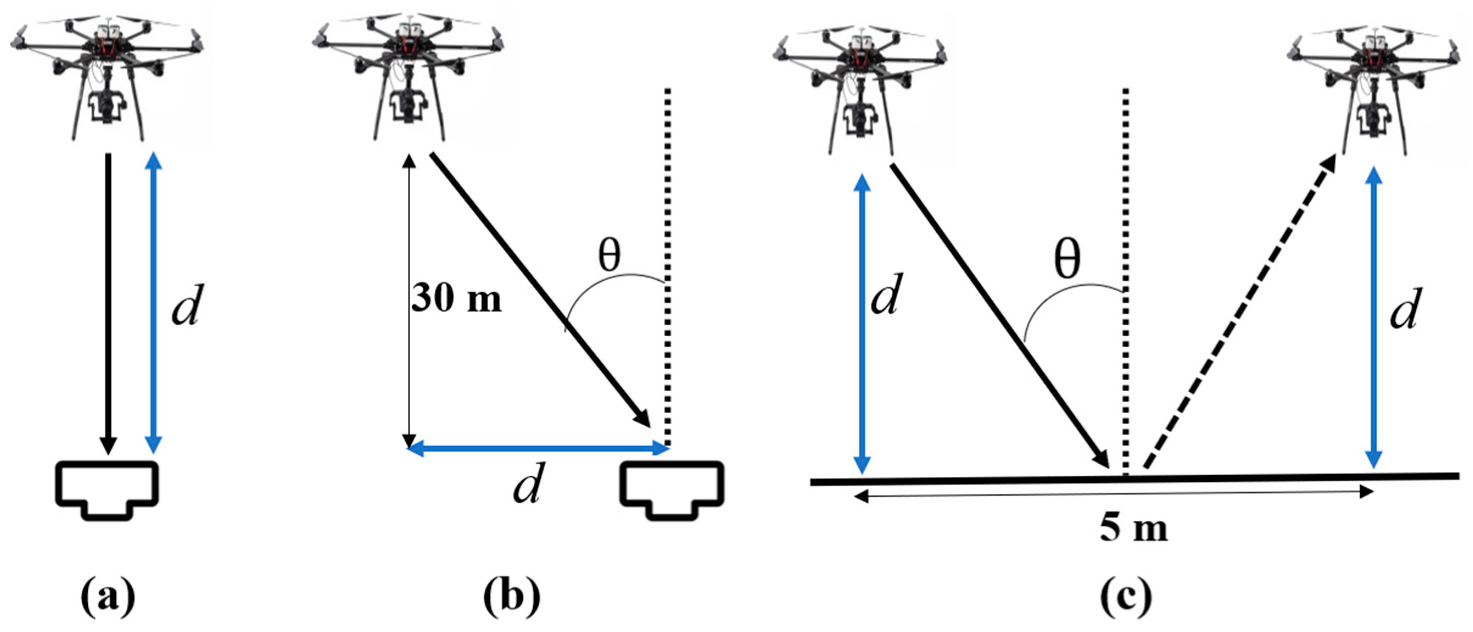
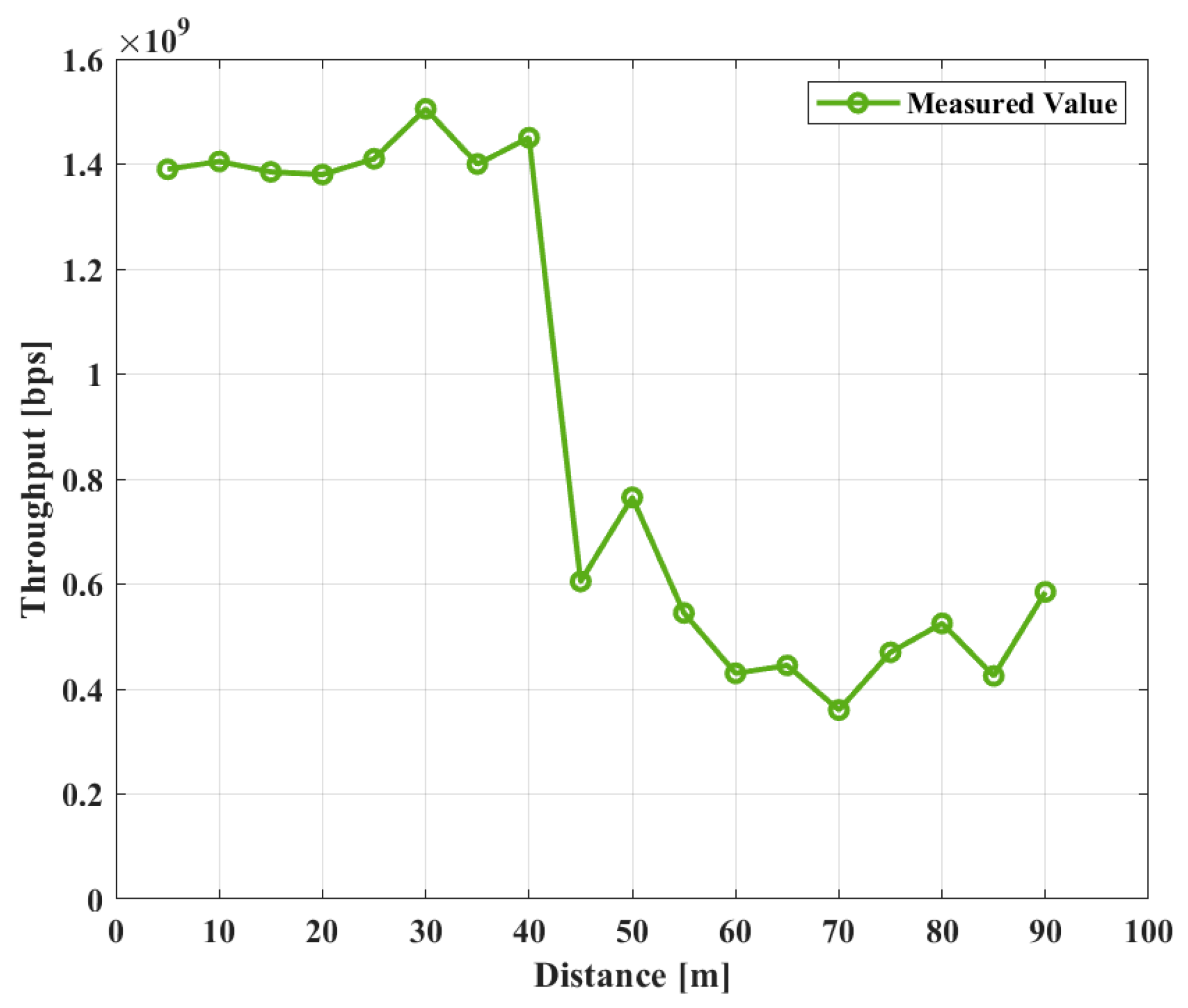
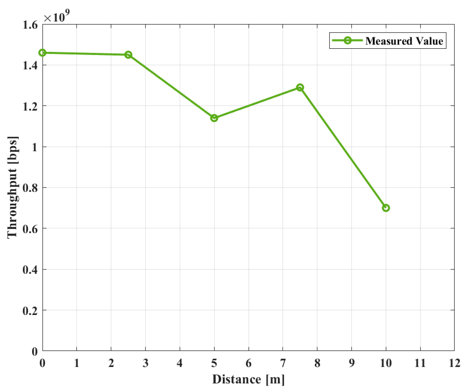
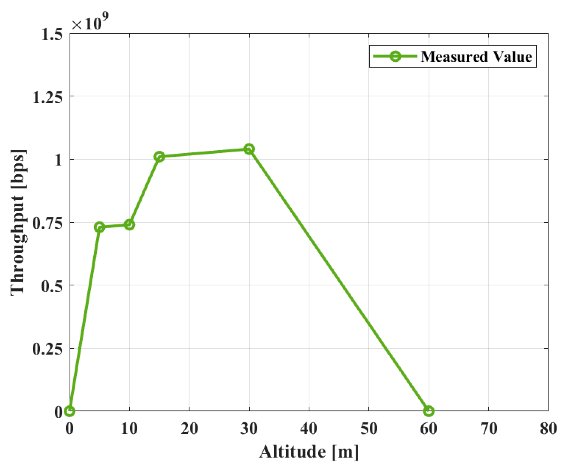
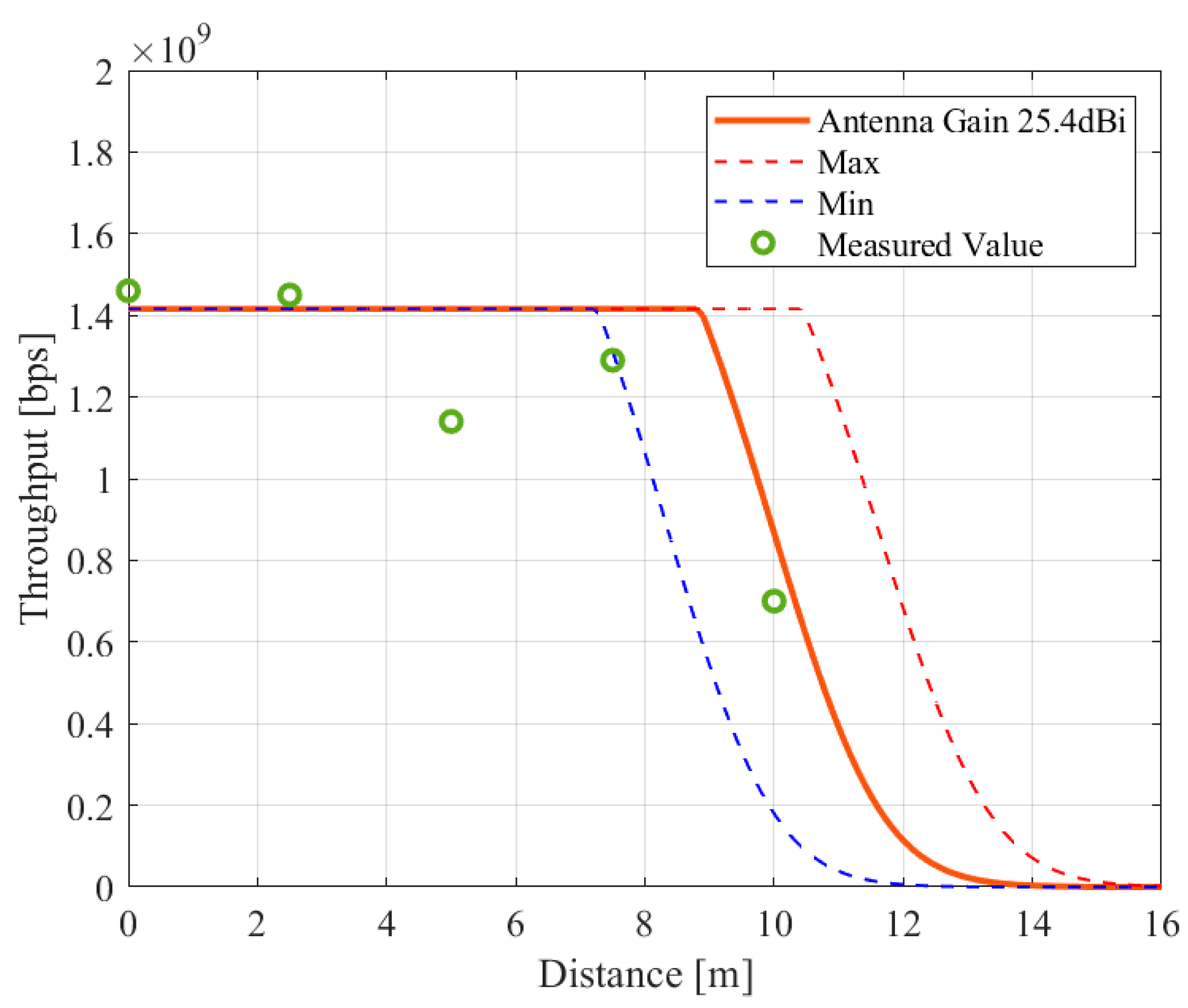
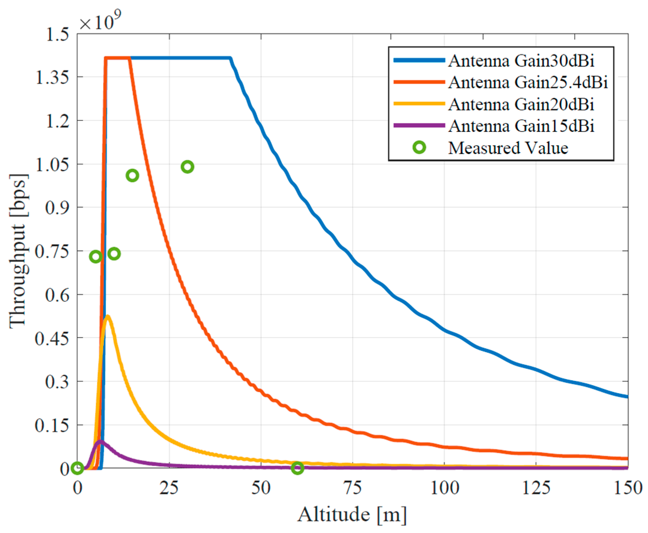
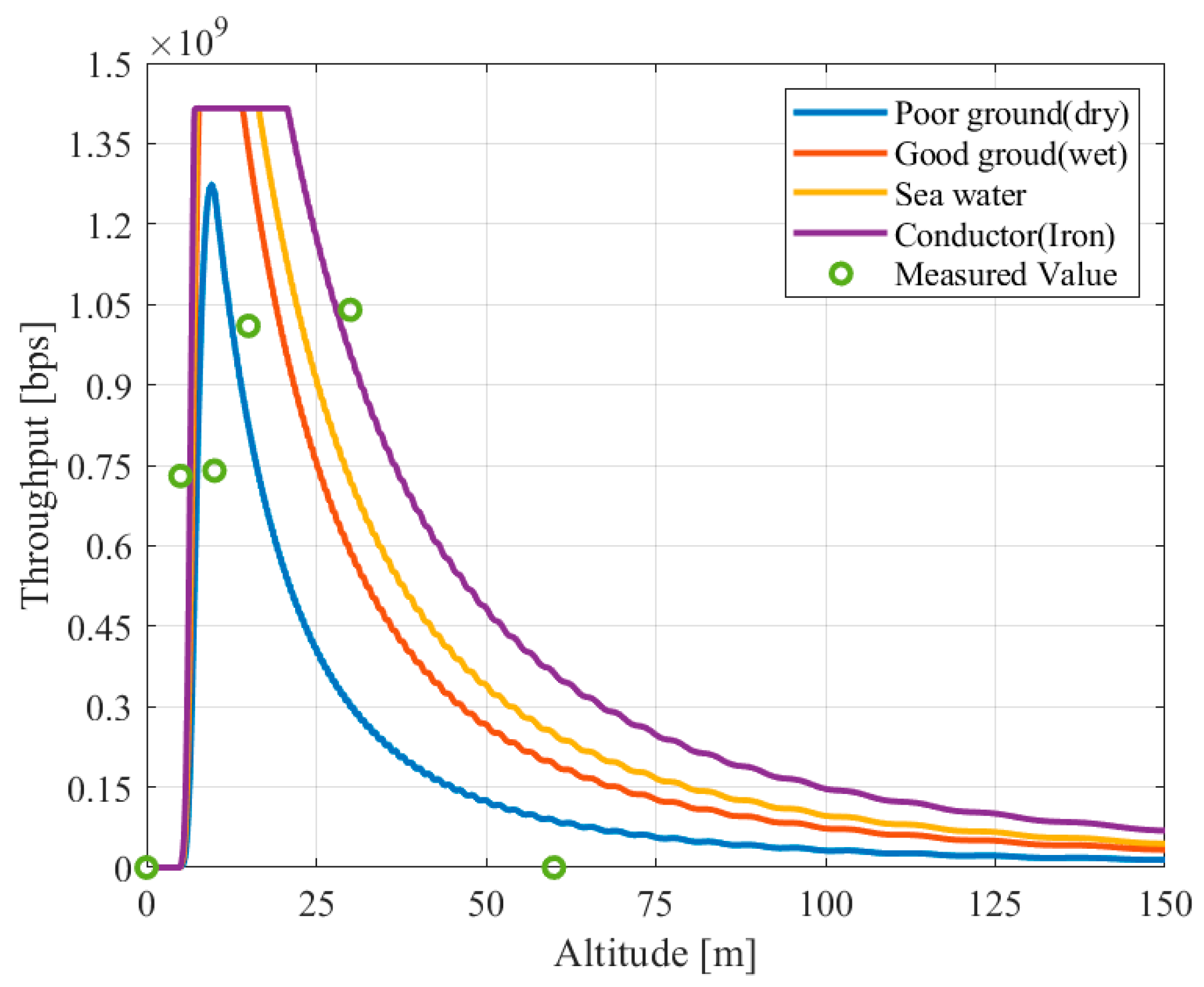
In this paper, we investigated the radio propagation characteristics of mmWave UAV BSs for the construction of temporary network areas during contingencies such as large-scale events and disasters, based on both numerical evaluations and demonstrative experiments. We evaluated the distance and coverage characteristics between access UAVs and terminals and analyzed the effect of radio interference due to earth reflection. Our findings revealed that our experimental devices, utilizing the IEEE802.11ad standard, could achieve high-capacity communication at a rate of nearly 1.5 Gbps. Also, ground reflections were confirmed as sources of interference. Furthermore, the consistency across the three sets of evaluation results underscores the trustworthiness of our measurements. Consequently, the theoretical model we established is a valuable reference for subsequent model-driven inquiries in system design.
However, since there is still a small gap between the measurement and theoretical results, our future endeavors will encompass more detailed investigations, e.g., to consider positional inaccuracies observed during the experiments. Given that our demonstrative experiment inherently operates in a three-dimensional (3D) space, our numerical evaluations require a more intricate 3D representation. For instance, accounting for potential shifts in the antenna’s received polarization due to possible 3D beam misalignments is essential. Also, while our current study centered on access UAVs, an expanded focus is vital—encompassing backhaul UAVs and the broader mmWave UAV BS network—to comprehensively understand the radio propagation characteristics of our proposed system. The findings presented in this paper indicated that additional errors like positioning ones are likely to occur in real UAV-based networks that might degrade or improve the system’s performance unexpectedly. It reconfirms the importance of experiment-based performance evaluation of a system like in this paper, rather than only computer-based theoretical work. Also, this paper indicates the significance of considering practical parameters in realistic environments when designing a UAV-based network that might involve many UAVs rather than only several UAVs like in this paper. One of our future works will include detailed investigation of the PHY/MAC conversion factor α . In addition, this experiment was conducted with a limited amount of data due to battery issues and the need for a license to fly drones in Japan. In future verification experiments, we will devise ways to secure a larger amount of data so that not only throughput but also other KPIs, e.g., delays, can be measured.

Author Contributions

Conceptualization, G.K.T.; methodology, R.M.; software, R.M.; validation, G.K.T., R.M. and J.N.; formal analysis, G.K.T., R.M. and J.N.; investigation, G.K.T., R.M. and J.N.; resources, G.K.T. and K.S.; data creation, R.M.; writing—original draft preparation, R.M.; writing—review and editing, G.K.T., R.M., J.N. and K.S.; visualization, R.M.; supervision, G.K.T., J.N. and K.S.; project administration, G.K.T. and J.N.; funding acquisition, G.K.T. and J.N. All authors have read and agreed to the published version of the manuscript.

Funding

This research was supported by the Strategic Information and Communications R&D Promotion Programme (SCOPE) by the Ministry of Internal Affairs and Communications, Japan (receipt number JP235003015).

Data Availability Statement

The data presented in this study are available in this article.

Acknowledgments

We would like to express our sincere gratitude to all the individuals and organizations that have contributed to the publication of this work. We would especially like to thank Tomoki Morioka, who helped to conduct the experiments.

Conflicts of Interest

The authors declare no conflicts of interest. The funders had no role in the design of this study; in the collection, analyses, experiments, or interpretation of data; in the writing of the manuscript; or in the decision to publish the results.

Appendix A

The basic specifications of IEEE802.11ad are depicted in the below table. In this table, IEEE802.11ad has four channels in Japan [71].
Table A1. Basic specifications of IEEE802.ad.
Frequency Band60 GHz
Max Antenna Power24 dBm
Max Antenna Gain47 dBi
Number of Channels4
Channel Width2.16 GHz
Modulation MethodSC/OFDM

Appendix B

The below table describes the relationship between the modulation method and throughput in each MCS of IEEE802.11ad [68].
Table A2. Relationship between throughput, modulation scheme, etc. in each MCS of IEEE802.11ad.
MCSModulationCode RateData Rate [Mbps]EVM [dB]
1π/2 BPSK1/2385.00−6
2π/2 BPSK1/2770.00−7
3π/2 BPSK5/8962.50−9
4π/2 BPSK3/41155.00−10
5π/2 BPSK13/161251.25−12
6π/2 QPSK1/21540.00−11
7π/2 QPSK5/81925.00−12
8π/2 QPSK3/42310.00−13
9π/2 QPSK13/162502.50−15
10π/2 16QAM1/23080.00−19
11π/2 16QAM5/83850.00−20
12π/2 16QAM3/44620.00−21
13SQPSK1/2693.00−7
14SQPSK5/8866.25−9
15QPSK1/21386.00−10
16QPSK5/81732.50−11
17QPSK3/42079.00−13
1816 QAM1/22772.00−15
1916 QAM5/83465.00−17
2016 QAM3/44158.00−19
2116 QAM13/164504.00−20
2264 QAM5/85197.00−22
2364 QAM3/46237.00−24
2464 QAM13/166756.75−26

Abbreviations

5G5th generation mobile communication system
IoTInternet of Things
mmWavemillimeter wave
UAVunmanned aerial vehicle
BS
AP
base station
access point
SNSsocial networking service
ESCelectric speed controller
SIRsignal to interference power ratio
LOSline of sight
RMSroot mean square
3Dthree-dimensional

References

  1. Cisco Visual Networking Index: Global Mobile Data Traffic Forecast Update, 2017–2022. Available online: https://twiki.cern.ch/twiki/pub/HEPIX/TechwatchNetwork/HtwNetworkDocuments/white-paper-c11-741490.pdf (accessed on 21 November 2023).
  2. Ministry of Internal Affairs and Communications. Current Status of Mobile Communication Traffic (June 2023). 2023. Available online: https://www.soumu.go.jp/johotsusintokei/field/data/gt010602.pdf (accessed on 17 October 2023).
  3. Ministry of Internal Affairs and Communications. Vision toward Beyond 5G. Available online: https://www.soumu.go.jp/main_sosiki/joho_tsusin/eng/presentation/pdf/Vision_toward_Beyond_5G.pdf (accessed on 21 November 2023).
  4. Beyond 5G/6G White Paper. June 2023. Available online: https://beyond5g.nict.go.jp/images/download/NICT_B5G6G_WhitePaperEN_v3_0.pdf (accessed on 21 November 2023).
  5. NOKIA. Communications in the 6G Era White Paper. 2023. Available online: https://onestore.nokia.com/asset/207766 (accessed on 21 November 2023).
  6. NTT DOCOMO. White Paper 5G Evolution and 6G, January 2023 (Version5.0). Available online: https://www.docomo.ne.jp/english/binary/pdf/corporate/technology/whitepaper_6g/DOCOMO_6G_White_PaperEN_v5.0.pdf (accessed on 21 November 2023).
  7. ERICSSON. 6G-Connectiong a Cyber-Physical World, February 2022. Available online: https://www.ericsson.com/4927de/assets/local/reports-papers/white-papers/6g--connecting-a-cyber-physical-world.pdf (accessed on 23 November 2023).
  8. Ministry of Internal Affairs and Communications. Announcement of Quarterly Data on the Number of Telecommunications Service Contracts and Market Share (FY2022 Q2 (End of September)). 16 December 2022. Available online: https://www.soumu.go.jp/main_sosiki/joho_tsusin/eng/pressrelease/2022/12/16_03.html (accessed on 17 October 2023).
  9. Bastug, E.; Bennis, M.; Debbah, M. Living on the edge: The role of proactive caching in 5G wireless networks. IEEE Commun. Mag. 2014, 52, 82–89. [Google Scholar] [CrossRef]
  10. Rappaport, T.S.; Sun, S.; Mayzus, R.; Zhao, H.; Azar, Y.; Wang, K.; Wong, G.N.; Schulz, J.K.; Samimi, M.; Gutierrez, F. Millimeter Wave Mobile Communications for 5G Cellular: It Will Work! IEEE Access 2013, 1, 335–349. [Google Scholar] [CrossRef]
  11. Hong, W.; Baek, K.-H.; Ko, S. Millimeter-Wave 5G Antennas for Smartphones: Overview and Experimental Demonstration. IEEE Trans. Antennas Propag. 2017, 65, 6250–6261. [Google Scholar] [CrossRef]
  12. Telecom Regulatory Authority of India. Consultation Paper on Digital Transformation through 5G Ecosystem. September 2023. Available online: https://trai.gov.in/sites/default/files/CP_29092023.pdf (accessed on 24 November 2023).
  13. Zhang, S.; Wu, Q.; Xu, S.; Li, G.Y. Fundamental Green Tradeoffs: Progresses, Challenges, and Impacts on 5G Networks. IEEE Commun. Surv. Tutor. 2017, 19, 33–56. [Google Scholar] [CrossRef]
  14. Jagatheesaperumal, S.K.; Rahouti, M. Building Digital Twins of Cyber Physical Systems With Metaverse for Industry 5.0 and Beyond. IT Prof. 2022, 24, 34–40. [Google Scholar] [CrossRef]
  15. Inokuchi, K.; Nakazato, J.; Tsukada, M.; Esaki, H. Semantic Digital Twin for interoperability and comprehensive management of data assets. In Proceedings of the 2023 IEEE International Conference on Metaverse Computing, Networking and Applications, Kyoto, Japan, 26–28 June 2023. [Google Scholar] [CrossRef]
  16. Verma, A.; Bhattacharya, P.; Madhani, N.; Trivedi, C.; Bhushan, B.; Tanwar, S.; Sharma, G.; Bokoro, P.N.; Sharma, R. Blockchain for Industry 5.0: Vision, Opportunities, Key Enablers, and Future Directions. IEEE Access 2022, 10, 69160–69199. [Google Scholar] [CrossRef]
  17. Jain, D.K.; Li, Y.; Er, M.J.; Xin, Q.; Gupta, D.; Shankar, K. Enabling Unmanned Aerial Vehicle Borne Secure Communication With Classification Framework for Industry 5.0. IEEE Trans. Ind. Inform. 2022, 18, 5477–5484. [Google Scholar] [CrossRef]
  18. Mohsan, S.A.H.; Othman, N.Q.H.; Li, Y.; Alsharif, M.H.; Khan, M.A. Unmanned Aerial Vehicles (UAVs): Practical Aspects, Applications, Open Challenges, Security Issues, and Future Trends. Intell. Serv. Robot. 2023, 16, 109–137. [Google Scholar] [CrossRef]
  19. Nex, F.; Remondino, F. UAV for 3D mapping applications: A review. Appl. Geomat. 2014, 6, 1–15. [Google Scholar] [CrossRef]
  20. Doherty, P.; Rudol, P. A UAV Search and Rescue Scenario with Human Body Detection and Geolocalization. In AI 2007: Advances in Artificial Intelligence; Orgun, M.A., Thornton, J., Eds.; Springer: Berlin/Heidelberg, Germany, 2007; pp. 1–13. [Google Scholar] [CrossRef]
  21. Villa, T.F.; Gonzalez, F.; Miljievic, B.; Ristovski, Z.D.; Morawska, L. An Overview of Small Unmanned Aerial Vehicles for Air Quality Measurements: Present Applications and Future Prospectives. Sensors 2016, 16, 1072. [Google Scholar] [CrossRef]
  22. Mohsan, S.A.H.; Khan, M.A.; Noor, F.; Ullah, I.; Alsharif, M.H. Towards the Unmanned Aerial Vehicles (UAVs): A Comprehensive Review. Drones 2022, 6, 147. [Google Scholar] [CrossRef]
  23. Ministry of Internal Affairs and Communications, Japan. White Paper Information and Communications. 13 April 2017. Available online: https://www.soumu.go.jp/johotsusintokei/whitepaper/eng/WP2017/2017-index.html (accessed on 17 October 2023).
  24. Federal Communications Commission. The 2017 Atlantic Hurricane Season’s Impact on Communications: Report and Recommendations, Public Safety and Homeland Security, 45 L Street NE, Washington, DC, 20554, 24 August 2018. Available online: https://docs.fcc.gov/public/attachments/DOC-353805A1.pdf (accessed on 23 November 2023).
  25. Erjongmanee, S.; Ji, C. Large-Scale Network-Service Disruption: Dependencies and External Factors. IEEE Trans. Netw. Serv. Manag. 2011, 8, 375–386. [Google Scholar] [CrossRef]
  26. Ochoa, S.F.; Santos, R. Human-centric wireless sensor networks to improve information availability during urban search and rescue activities. Inf. Fusion 2015, 22, 71–84. [Google Scholar] [CrossRef]
  27. Erdelj, M.; Natalizio, E.; Chowdhury, K.R.; Akyildiz, I.F. Help from the Sky: Leveraging UAVs for Disaster Management. IEEE Pervasive Comput. 2017, 16, 24–32. [Google Scholar] [CrossRef]
  28. Ghafoor, S.; Sutton, P.D.; Sreenan, C.J.; Brown, K.N. Cognitive radio for disaster response networks: Survey, potential, and challenges. IEEE Wirel. Commun. 2014, 21, 70–80. [Google Scholar] [CrossRef]
  29. Takahashi, T.; Yamamoto, H.; Fukumoto, N.; Aono, S.; Yamazaki, K. Evaluation of Network Metrics for Detecting Mobile Network Congestion during Large-Scale Events. IEICE Trans. Commun. 2014, 6, 1102–1105. [Google Scholar]
  30. Shinbo, H.; Kunisawa, Y.; Sakai, T.; Kitatsuji, Y.; Endo, A.; Tanaka, K. Flying Base station for Temporary Mobile Communications in an Area Affected by a Disaster. In Proceedings of the 2018 5th International Conference on Information and Communication Technologies for Disaster Management (ICT-DM), Sendai, Japan, 4–7 December 2018. [Google Scholar] [CrossRef]
  31. Heath, R.W.; González-Prelcic, N.; Rangan, S.; Roh, W.; Sayeed, A.M. An Overview of Signal Processing Techniques for Millimeter Wave MIMO Systems. IEEE J. Sel. Top. Signal Process. 2016, 10, 436–453. [Google Scholar] [CrossRef]
  32. Roh, W.; Seol, J.-Y.; Park, J.; Lee, B.; Lee, J.; Kim, Y.; Cho, J.; Cheun, K.; Aryanfar, F. Millimeter-wave beamforming as an enabling technology for 5G cellular communications: Theoretical feasibility and prototype results. IEEE Commun. Mag. 2014, 52, 106–113. [Google Scholar] [CrossRef]
  33. Tran, G.K.; Ozasa, M.; Nakazato, J. NFV/SDN as an Enabler for Dynamic Placement Method of mmWave Embedded UAV Access Base Stations. Network 2022, 2, 479–499. [Google Scholar] [CrossRef]
  34. Lyu, J.; Zeng, Y.; Zhang, R.; Lim, T.J. Placement Optimization of UAV-Mounted Mobile Base Stations. IEEE Commun. Lett. 2017, 21, 604–607. [Google Scholar] [CrossRef]
  35. Ohishi, M.K. Impacts by Mega-Constellations to Astronomical Observations. Astron. Her. 2020, 113, 183–187. (In Japanese) [Google Scholar]
  36. Guillen-Perez, A.; Cano, M.-D. Flying Ad Hoc Networks: A New Domain for Network Communications. Sensors 2018, 18, 3571. [Google Scholar] [CrossRef] [PubMed]
  37. Semkin, V.; Huhtinen, I. Millimeter-wave UAV-based Channel Measurement Setup. In Proceedings of the 2021 IEEE 93rd Vehicular Technology Conference (VTC2021-Spring), Helsinki, Finland, 25–28 April 2021; pp. 1–2. [Google Scholar] [CrossRef]
  38. Bai, L.; Huang, Z.; Zhang, X.; Cheng, X. A Non-Stationary 3D Model for 6G Massive MIMO mmWave UAV Channels. IEEE Trans. Wirel. Commun. 2022, 21, 4325–4339. [Google Scholar] [CrossRef]
  39. Chowdhury, M.Z.; Shahjalal, M.; Hasan, M.K.; Jang, Y.M. The Role of Optical Wireless Com-munication Technologies in 5G/6G and IoT Solutions: Prospects, Directions, and Challenges. Appl. Sci. 2019, 9, 4367. [Google Scholar] [CrossRef]
  40. Tran, G.K.; Nakamura, M.; Nishiuchi, H.; Sakaguchi, K.; Santos, R.; Koslowski, K. Outdoor Ex-periment of mmWave Meshed Backhaul for Realtime Edge Content Delivery. In Proceedings of the 2019 IEEE Wire-less Communications and Networking Conference Workshop (WCNCW), Marrakech, Morocco, 15–18 April 2019; pp. 1–6. [Google Scholar] [CrossRef]
  41. Al-Hourani, A.; Sithamparanathan, K.; Lardner, S. Optimal LAP Altitude for Maximum Coverage. IEEE Wirel. Commun. Lett. 2014, 3, 569–572. [Google Scholar] [CrossRef]
  42. Tran, G.K.; Okada, T. Design of Antenna Polarization Plane for Concurrent Uplink/Downlink Drone Networks. Electronics 2023, 12, 3045. [Google Scholar] [CrossRef]
  43. MohamedZain, A.O.; Hou, L.W.; Chua, H.; Yap, K.; Boon, L.K. The Design and Fabrication of Multiple-Transmitter Coils and Single-Receiver Coils for a Wireless Power Transfer System to Charge a 3s LiPo Drone’s Battery. Energies 2023, 16, 3629. [Google Scholar] [CrossRef]
  44. SoftBank News. Trapped by an Earthquake, Saved by a Drone. Demonstration Shows How it Can be Done. SoftBank News. 10 February 2023. Available online: https://www.softbank.jp/en/sbnews/entry/20230210_01 (accessed on 20 September 2023).
  45. Khawaja, W.; Ozdemir, O.; Guvenc, I. UAV Air-to-Ground Channel Characterization for mmWave Systems. In Proceedings of the 2017 IEEE 86th Vehicular Technology Conference (VTC-Fall), Toronto, ON, Canada, 24–27 September 2017; pp. 1–5. [Google Scholar] [CrossRef]
  46. Masaoka, R.; Tran, G.K. Construction and Demonstration of Access Link for Millimeter Wave UAV Base Station Network. In Proceedings of the 2023 Fourteenth International Conference on Ubiquitous and Future Networks (ICUFN), Paris, France, 4–7 July 2023; pp. 163–167. [Google Scholar] [CrossRef]
  47. Morioka, T.; Ozasa, M.; Tran, G.K. Construction of Experimental System for mm-Wave UAV Base Station. IEICE Tech. Rep. 2022, 121, 177–182. (In Japanese) [Google Scholar]
  48. Nakamura, M.; Nishiuchi, H.; Nakazato, J.; Koslowski, K.; Daube, J.; Santos, R.; Tran, G.K.; Sakaguchi, K. Experimental Verification of SDN/NFV in Integrated mmWave Access and Mesh Backhaul Networks. IEICE Trans. Commun. 2021, 104, 217–228. [Google Scholar] [CrossRef]
  49. Technical Specification; 5G.; NR. User Equipment (UE) Radio Transmission and Reception; Part 1: Range 1 Standalone (3GPP TS 38.101–1 version 15.1.0 Release 15). March 2018. Available online: https://www.3gpp.org/ftp//Specs/archive/38_series/38.101-1/38101-1-f10.zip (accessed on 21 November 2023).
  50. Sengupta, A.; Jin, F.; Zhang, R.; Cao, S. mm-Pose: Real-Time Human Skeletal Posture Estimation Using mmWave Radars and CNNs. IEEE Sens. J. 2020, 20, 10032–10044. [Google Scholar] [CrossRef]
  51. Wei, Z.; Zhang, F.; Chang, S.; Liu, Y.; Wu, H.; Feng, Z. MmWave Radar and Vision Fusion for Object Detection in Autonomous Driving: A Review. Sensors 2022, 22, 2542. [Google Scholar] [CrossRef] [PubMed]
  52. Takahashi, K.; Takinami, K. Industrial Trends and Future View of Millimeter Wave Wireless Technology Using IEEE802.11ad/WiGig. J. Inst. Electron. Inf. Commun. Eng. 2015, 98, 899–904. (In Japanese) [Google Scholar]
  53. Mackay, M.; Raschella, A.; Toma, O. Modelling and Analysis of Performance Characteristics in a 60 Ghz 802. 11ad Wireless Mesh Backhaul Network for an Urban 5G Deployment. Future Internet 2022, 14, 34. [Google Scholar] [CrossRef]
  54. Nitsche, T.; Cordeiro, C.; Flores, A.B.; Knightly, E.W.; Perahia, E.; Widmer, J.C. IEEE 802.11 ad: Directional 60 GHz communication for multi-Gigabit-per-second Wi-Fi. IEEE Commun. Mag. 2014, 52, 132–141. [Google Scholar] [CrossRef]
  55. Mozaffari, M.; Saad, W.; Bennis, M.; Nam, Y.-H.; Debbah, M. A Tutorial on UAVs for Wireless Networks: Applications, Challenges, and Open Problems. IEEE Commun. Surv. Tutor. 2019, 21, 2334–2360. [Google Scholar] [CrossRef]
  56. Beard, R.W.; McLain, T.W. Small Unmanned Aircraft: Theory and Practice; Princeton University Press: Princeton, NJ, USA, 2012. [Google Scholar] [CrossRef]
  57. Isabelle, B.; Serge, H.; Andrea, M.; Romain, H.; Tinku, R.; Sandy, A. Rapidly Deployable Network for Tactical Applications: Aerial Base Station with Opportunistic Links for Unattended and Temporary Events ABSOLUTE Example. In Proceedings of the MILCOM 2013: 2013 IEEE Military Communications Conference, San Diego, CA, USA, 18–20 November 2013; pp. 1116–1120. [Google Scholar] [CrossRef]
  58. Jaber, R.A.; Sikder, M.S.; Hossain, R.A.; Malia, K.F.N.; Rahman, M.A. Unmanned Aerial Vehicle for Cleaning and Firefighting Purposes. In Proceedings of the 2021 2nd International Conference on Robotics, Electrical and Signal Processing Techniques (ICREST), Dhaka, Bangladesh, 5–7 January 2021; pp. 673–677. [Google Scholar] [CrossRef]
  59. Wang, X.; Wu, P.; Hu, Y.; Cai, X.; Song, Q.; Chen, H. Joint Trajectories and Resource Allocation Design for Multi-UAV-Assisted Wireless Power Transfer with Nonlinear Energy Harvesting. Drones 2023, 7, 354. [Google Scholar] [CrossRef]
  60. DJI Matrice 600 Pro. Available online: https://www.dji.com/jp/matrice600-pro (accessed on 1 October 2023).
  61. Karasawa, Y. Friis Formula. Technical Report YK-040. 10 January 2020. Available online: http://www.radio3.ee.uec.ac.jp/ronbun/TR-YK-040_Friis-Formula.pdf (accessed on 23 December 2023). (In Japanese).
  62. Barakat, A.; Allam, A.; Elsadek, H.; Abdel-Rahman, A.B.; Pokharel, R.K.; Kaho, T. Improved gain 60GHz CMOS antenna with N-well grid. IEICE Electron. Express 2016, 13, 20151115. [Google Scholar] [CrossRef]
  63. Toyoda, I.; Ando, M.; Iigusa, K.; Sawada, H.; Seki, T.; Nishi, S.; Kitazawa, S.; Miura, A.; Fujita, Y.; Uchimura, H.; et al. Mathematical Antenna Model with a Rotationally Symmetric Beam for System Design of Wireless Personal Area Networks. IEICE Trans. Commun. (Jpn. Ed.) 2010, J93-B, 781–790. [Google Scholar]
  64. Feuerstein, M.J.; Blackard, K.L.; Rappaport, T.S.; Seidel, S.Y.; Xia, H.H. Path loss, delay spread, and outage models as functions of antenna height for microcellular system design. IEEE Trans. Veh. Technol. 1994, 43, 487–498. [Google Scholar] [CrossRef]
  65. Rusek, F.; Persson, D.; Lau, B.K.; Larsson, E.G.; Marzetta, T.L.; Edfors, O.; Tufvesson, F. Scaling Up MIMO: Opportunities and Challenges with Very Large Arrays. IEEE Signal Process. Mag. 2013, 30, 40–60. [Google Scholar] [CrossRef]
  66. Parsons, J.D. The Mobile Radio Propagation Channel, 2nd ed.; John Wiley & Sons Ltd.: Hoboken, NJ, USA, 2000. [Google Scholar]
  67. Shannon, C.E. A mathematical theory of communication. Bell Syst. Tech. J. 1948, 27, 379–423. [Google Scholar] [CrossRef]
  68. IEEE Std 802.11ad-2012; IEEE Standard for Information technology—Telecommunications and information exchange between systems—Local and metropolitan area networks--Specific requirements-Part 11: Wireless LAN Medium Access Control (MAC) and Physical Layer (PHY) Specifications Amendment 3: Enhancements for Very High Throughput in the 60 GHz Band. IEEE: Piscataway, NJ, USA, 2012. [CrossRef]
  69. Chen, D.; Yen, M.; Lin, P.; Groff, S.; Lampo, R.; Mcinerney, M.; Ryan, J. A Corrosion Sensor for Monitoring the Early-Stage Environmental Corrosion of A36 Carbon Steel. Materials 2014, 7, 5746–5760. [Google Scholar] [CrossRef] [PubMed]
  70. Fukuchi, T.; Fuse, N.; Mizuno, M.; Fukunaga, K. Measurement of Surface Roughness of Dielectric Materials using Terahertz Waves. IEEJ Trans. Fundam. Mater. 2015, 135, 450–455. [Google Scholar] [CrossRef]
  71. Yamada, A.; Nojima, D.; Asai, T. Trends in International Standardization of Wireless LAN Related Systems. IEICE Commun. Soc. Mag. 2016, 10, 74–79. [Google Scholar] [CrossRef]
Figure 1. Overview of system architecture [33].
Futureinternet 16 00005 g001
Figure 2. Beamforming procedure.
Futureinternet 16 00005 g002
Figure 3. Architecture of multi-copter UAV.
Futureinternet 16 00005 g003
Figure 4. Experimental field. (a) Photo taken from the ground. (b) Satellite photo seen from Google Earth.
Futureinternet 16 00005 g004
Figure 5. (a) Photograph of the antenna used in the experiment. (b) Numerical analysis of the directivity [47].
Futureinternet 16 00005 g005
Figure 6. UAV with millimeter-wave device.
Futureinternet 16 00005 g006
Figure 7. Extended millimeter-wave communication device mounted on a UAV.
Futureinternet 16 00005 g007
Figure 8. Diagram of experiment scenario. (a) Direct experiment. (b) Coverage measurement. (c) Ground reflection experiment.
Futureinternet 16 00005 g008
Figure 9. Experimental results of the direct experiment.
Futureinternet 16 00005 g009
Figure 10. Experimental results of the coverage measurement.
Futureinternet 16 00005 g010
Figure 11. Experimental observations of ground reflection.
Futureinternet 16 00005 g011
Figure 12. Experimental results of the ground reflection experiment.
Futureinternet 16 00005 g012
Figure 13. Antenna gain model.
Futureinternet 16 00005 g013
Figure 14. Two-ray ground reflection model.
Futureinternet 16 00005 g014
Figure 15. Transmit spectrum mask [68].
Futureinternet 16 00005 g015
Figure 16. Numerical results of direct experiment.
Futureinternet 16 00005 g016
Figure 17. Numerical results of coverage measurement: (a) UAV 10 m altitude, (b) UAV 30 m altitude, and (c) UAV 50 m altitude.
Futureinternet 16 00005 g017
Figure 18. Numerical results of ground reflection with different horizontal separation distance: (a) 5 m, (b) 10 m, and (c) 30 m.
Futureinternet 16 00005 g018
Figure 19. Comparative results of direct experiment.
Futureinternet 16 00005 g019
Figure 20. Comparative results of coverage measurement.
Futureinternet 16 00005 g020
Figure 21. Comparison of direct experiments considering positioning error.
Futureinternet 16 00005 g021
Figure 22. Comparison of coverage measurements considering positioning error.
Futureinternet 16 00005 g022
Figure 23. Comparative results of ground reflection experiment.
Futureinternet 16 00005 g023
Figure 24. Comparative results of ground reflection experiment for various ground materials.
Futureinternet 16 00005 g024
Figure 25. Image of scattering wave arrival.
Futureinternet 16 00005 g025
Figure 26. Distribution of generated scattering waves.
Futureinternet 16 00005 g026
Figure 27. Comparison of ground reflection Monte Carlo simulation with scattering waves.
Futureinternet 16 00005 g027
Figure 28. Comparison of roughness of ground reflection Monte Carlo simulation with 3 scattering waves and different surface roughness values: (a) 10 μm, (b) 50 μm, (c) 500 μm, and (d) 1000 μm.
Futureinternet 16 00005 g028
Figure 29. Comparison of ground reflection Monte Carlo simulation with scattering waves considering positioning error.
Futureinternet 16 00005 g029
Table 1. Comparison of two types of UAV features.
Multi-CopterFixed Wing
Fly timeShortLong
Onboard weightLightHeavy
Vertical take offSupportNot Supported
Air stopSupportNot Supported
Flight altitudeLowHigh
Table 2. Antenna specifications used in the experiment.
ManufacturerIntel
Size210 mm × 115 mm × 95 mm
Weight0.87 kg
Wireless ChipWireless-AC 17265
CPUIntel Core i3-4010U
Wireless ChipTri-Band Wireless-AC 17265
Wireless StandardIEEE802.11 ad
Array Antenna10041R
Power Supply65 W
Max MCS12
Max Transmission Speed4.620 Gbps
Antenna Gain25.4 dBi
Scan Angle (deg.)±13.5 (hor), ±7 (Ver)
Table 3. Matrice 600 pro specifications.
CategorySpecification
Size1668 mm × 1518 mm × 727 mm
Weight9.5 kg
Max Takeoff Weight15.5 kg
Hovering Time32 min
Max Wind Resistance25°
Max Speed40 km/h, 65 km/h (Windless)
Battery Capacity4500 mAh
Battery Voltage22.2 V
Number of Batteries6
Max Transmission Distance3.5 km
Table 4. Experiment equipment.
ItemPurpose
MonitorTo be used as a screen for wireless devices
KeyboardTo operate wireless devices
PCTo check data
Safety CornTo accurately align the drone
Thermal BoxTo maintain battery temperature and efficiency
Table 5. Numerical evaluation parameters.
Frequency Band f 60 GHz
Wavelength λ (speed of light: 3.0 × 10⁸ m/s) 5.0 × 10 3 m
Transmission Power P t 15 dBm
Atmospheric Attenuation L o x 16 dB/km
Permittivity of Vacuum ε 0 8.854 × 10 12 F/m
Boltzmann’s Constant k q 1.38 × 10 23 J/K
Temperature K 290 K
Noise Figure10 dB
Bandwidth B 1.88 GHz
Max Antenna Gain15, 20, 25.4, 30 dBi
Scan Angle (deg.)±13.5
Table 6. Ground parameters for each material used in the numerical evaluation.
TypeDielectric ConstantConductivity (S/m)
Poor Soil (Dry) ε r = 7 σ = 1 × 10 3
Good Soil (Wet) ε r = 30 σ = 2 × 10 2
Sea ε r = 81 σ = 5
Conductor (Iron) ε r = σ = 10 7
Disclaimer/Publisher’s Note: The statements, opinions and data contained in all publications are solely those of the individual author(s) and contributor(s) and not of MDPI and/or the editor(s). MDPI and/or the editor(s) disclaim responsibility for any injury to people or property resulting from any ideas, methods, instructions or products referred to in the content.

