1. Introduction
Road intersections controlled by stop signs are commonly seen on road networks. At road intersections, several flows of traffic conflict with each other. Thus, accidents among vehicles are serious threats there. Several traffic techniques have been used to control safe and smooth mobility there, such as traffic lights, roundabouts, and stop signs [
1]. These techniques are selected after carefully evaluating traffic conditions indicating their installation is warranted and appropriate. However, some road intersections do not need an official traffic control device, particularly in residential areas [
2]. Driving laws have determined the right of way at road intersections based on their design and the road types on the intersection [
3].
Stop signs are required to assign right of way at road intersections, not to control speed or efficiency. They are often used at intersections that are not busy enough to install a traffic signal or a roundabout. The need for stop signs involves a trade-off between safety and delay [
4]. Stop signs have been required at road intersections when a less important road meets with the main road if there is a restricted view or a high accident record. Right-angle accidents can be reduced by the installation of stop signs when warranted. However, installing unrequired stop signs may increase rear-end accidents [
5]. Stop signs are mainly installed on road intersections designed in T-junction or four-leg road intersections. In the T-junction design, the stop sign is usually installed on the secondary road that reaches the main straight road [
6]. On the other hand, in four-leg road intersections, stop signs can be installed in all ways. This is when two main roads are at the intersection. However, if the four-leg road intersection contains main and secondary roads, the stop signs are installed at the two ways that belong to the secondary road [
5]. In all scenarios, drivers must stop completely before the installed stop sign.
After stopping at the road intersection controlled by stop signs, drivers have to follow the driving rules of that region to decide when to traverse the intersection. First to arrive, first to go, straight before turns, and right then left are the main driving rules for stopping vehicles at stop sign intersections [
5]. Drivers must first be aware of the stop sign’s existence, then the architecture of the signalized road intersection, and the traffic distribution of the competing traffic flow at that intersection. This is to decide when or how long to wait to pass the intersection. Due to bad weather conditions, obstacles, or heavy existing vehicles, drivers may miss seeing the stop sign. Moreover, the architecture of the road intersection and the characteristics of the competing traffic flows are not always clear to the drivers. Drivers may unsafely pass through the intersection because of the lack of knowledge regarding the type of road intersection or the competing traffic characteristics.
In this work, first, we aim to notify the driver of the existing stop signs at the next road intersection in case the driver misses the notification. The design of the road intersection and the real-time traffic characteristics of the competing traffic flows at the intersection are also reported to drivers there. Then, according to the driving rules and the traffic characteristics of the competing traffic flows at the intersection, the best driving behaviors (e.g., stop, move, decrease speed, or increase the speed) are determined and recommended to each vehicle that aims to pass through the intersection. The technology of vehicular ad-hoc networks (VANETs) is used to gather the traffic characteristics over the investigated area of interest. Vehicles are equipped with wireless transceivers that periodically transmit the basic traffic data of the vehicle. The traffic characteristics and context of each traffic flow at the intersection are evaluated internally in each vehicle based on the received messages from the neighboring vehicles. The existence of emergency vehicles and the context of the competing traffic flows are also considered in the obtained recommendations of the protocol. Moreover, digital maps are considered in each vehicle to determine the design of the coming road intersection. The proposed protocol aims mainly to assist drivers in passing through road intersections controlled by stop signs safely and efficiently.
Autonomous vehicles can use the proposed protocol to direct their robotic control system to drive safely and efficiently around stop sign road intersections. An extensive set of experiments on traffic distributions and contexts have been executed to test the protocol. These experiments show that the proposed protocol has successfully enhanced the safety conditions around road intersections controlled by stop signs. This is by reducing the percentage of accident occurrences. Moreover, the traffic efficiency of these road intersections has been enhanced by reducing the average waiting delay time of the vehicles. It has also increased the throughput of the road intersection and decreased the fuel consumption and gas emissions of traveling vehicles there.
The rest of this paper is organized as follows:
Section 2 investigates previous related studies in traffic management and driving assistant protocols.
Section 3 presents the considered design typologies of road intersections that can be controlled by stop signs and the number of competing traffic flows at each topology.
Section 4 introduces the proposed driving assistant protocol that helps drivers to pass through road intersections controlled by stop signs safely and efficiently. The performance of this protocol is evaluated in
Section 5. Finally,
Section 6 concludes the paper.
2. Related Work
Modern vehicles have been manufactured with several advanced equipment and sensors recently. Global positioning systems (GPS), digital maps, camcorders, and wireless transceivers are the most commonly added devices to vehicles [
1,
7]. These devices allow tracking of the vehicles’ movement and their main driving operations. Moreover, they enable the timely surveillance of the surrounding traffic for each vehicle. This introduces the chance to remotely and autonomously control the driving processes in each vehicle. Based on the surrounding traffic characteristics and the context in these driving control systems, the best driving operation is selected for each vehicle [
1,
8].
In the target of enhancing the safety and efficiency conditions on road networks, several intelligent driving systems have been proposed. Several smart systems of controlling vehicles and directing drivers have been developed in the literature to assist drivers on the road networks [
1]. These protocols have been developed and adapted to autonomous vehicles as well. These systems control the vehicles on the road networks according to the real-time traffic distribution and the context of the investigated road network [
1]. Stop signs are commonly seen on road networks. They are usually installed at road intersections in downtowns, before the pedestrian crosswalk, or on an entrance point to the highway, as well as popping up on school buses [
5]. Drivers must bring their vehicles to a full stop in front of these signs. This increases the surrounding area’s safety conditions and gives drivers time to make the right decision that avoids possible accidents. However, stop signs decrease the traffic fluency at road intersections [
9].
Vehicular networks and artificial intelligence systems have been used to develop a reliable and efficient controlling system for stop sign intersections. Some systems have been developed for small and low-traffic intersections. Pant et al. [
10] developed a traffic control system for two-way stop-controlled intersections with low traffic volumes. The technologies of neural networks and binary-logic models are in this system to predict the accepted and rejected gaps between vehicles on the main road. This helps to guarantee higher safety conditions at the secondary road of the investigated road intersection. VanMiddlesworth et al. [
8] also developed an unmanaged intersection control system for autonomous vehicles that replaces the stop sign. This system assumes an existing infrastructure at the intersection and mainly depends on peer-to-peer communications. Vehicles must call ahead an agent station at the intersection and reserve time and space for their traversal. This system achieves effective performance in small intersections and low-traffic scenarios. Kowshik et al. [
11] also designed intelligent intersections where traffic lights and stop signs are removed, and vehicles negotiate the intersection through an interaction of centralized and distributed decision-making technologies.
Most of the proposed traffic control systems in this field aim to enhance the traffic fluency and safety conditions on all-ways stop-signed road intersections [
12,
13]. Some smart advisory systems have been developed using the technology of RFID to provide drivers with earlier warning messages when they are approaching an unsignalized intersection [
14]. Bhatt and Tiwari [
12] developed a framework of smart traffic sign boards for smart cities. The latter framework depends on communication protocols among traveling vehicles and installed infrastructures on the road network. It keeps the drivers aware of their surrounding speed breakers, speed limits, schools, or U-turns ahead. Moreover, Saito et al. [
13] developed a driver assistance system with deceleration control and brake hold functions in stop sign intersections that alert the drivers of the approaching stop sign intersections to react by controlling their vehicles and forcing their complete stop there.
Safety conditions are the main consideration of previous studies on road intersections controlled by stop signs. Azimi et al. [
15] proposed a set of protocols to manage vehicles’ movements at these intersections safely. After that, these protocols were investigated in more realistic models and higher-concurrency aspect scenarios [
16]. This is in order to prepare these protocols for autonomous driving scenarios. Ragahu [
17] proposed a traffic control system for autonomous vehicles at stop sign intersections. This system first detects all vehicles and pedestrians approaching the investigated road intersection. Then, it sets the rules regarding the priorities assigned for vehicles to pass through that intersection. Moreover, Murphy et al. [
18] introduced another comprehensive traffic control system for autonomous vehicles following the traffic rules while traveling over the road network. It includes detecting road intersections controlled by stop signs and investigating the competing traffic flows. Then, it recommends that vehicles apply the driving rules there to ensure the safe sharing of that intersection among competing flows.
On the other hand, several research studies have tested smart stop-controlled intersection systems on naturalistic and GPS traffic data. Liu and Zhang [
19] explored the driver’s behaviors at all-way stop-controlled intersections with SHRP2 naturalistic driving data. From this study, the full stop rate at these intersections is only 20.2%. The main factors that influence stop decisions are drivers, vehicles, intersection geometry, maneuvering, and environmental features. Data collection methods could not determine when and where drivers began to decelerate. The normal deceleration behavior of current passenger vehicles is evaluated at stop-sign-controlled intersections on urban streets on the basis of in-vehicle Global Positioning System data [
7]. Finally, the traffic data are utilized for predicting crash-relevant violations at stop-sign-controlled intersections [
20]. This mainly helps to develop safer intersection driver assistance systems.
In this work, we are introducing a new driving assistance protocol for intelligent connected vehicles. This protocol alerts drivers of the stop signs’ existence. Then, it declares the driving rules around these stop signs. The proposed protocol assists drivers in making smooth and safe stops. It recommends the optimal deceleration rate for each vehicle based on the distance between that vehicle and the targeted intersection. Moreover, the protocol accurately considers the traveling speed of the recommended vehicle. Several stop sign intersection scenarios have been investigated and considered in this work. This provides a more comprehensive solution compared to previous studies in this field.
3. Types of Road Intersection Controlled by Stop Signs
Road intersections are the points where two or more roads cross each other. This introduces so many conflict points that lead to the high probability of collisions. Left turns are more likely to collide at road intersections than straight or right turns. Several techniques, mechanisms, and tools have been used to enhance the safety and efficiency of vehicles passing through road intersections. Stop signs are commonly used to control competing traffic flows at small and rural road intersections. Busy and fast junctions need traffic light control systems. Stop signs are used to be installed at four-leg and three-leg intersections. However, roundabouts control road junctions with more input and output flows [
21]. Different typologies have been designed for each road intersection controlled by stop signs, which are discussed in the rest of this section. Main roads are the roads that arrive at the intersection without being controlled by stop signs. However, secondary roads are the roads that arrive at the intersection and are controlled by stop signs.
3.1. Three-Leg Road Intersections
On downtown and rural road networks, these intersections are commonly seen. On these road networks, three-leg road intersections are created in one of two main architectural designs: T-junctions and Y-junctions. Stop signs can be installed on one or more input traffic flows to control safe traffic sharing of road intersections. In the rest of this section, we investigate all possible scenarios of installing stop signs at three-leg road intersections.
3.1.1. T-Junction
In this junction, three roads meet at the shared point, and a small road joins a larger road at a right angle (i.e., 90). The small road or the larger ones can be one- or two-direction roads. The stop signs can be installed in all or some input traffic flows (i.e., the flows moving towards the junction) according to the priority of passing through the intersection.
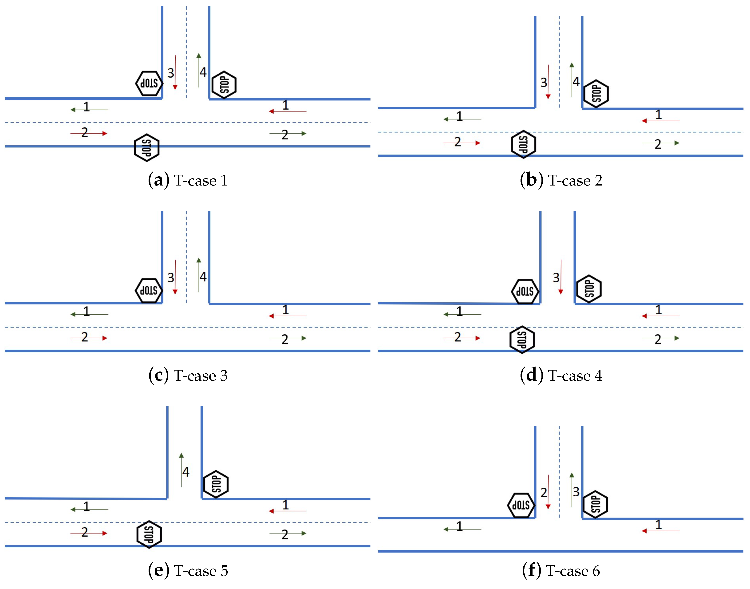
Figure 1 illustrates six possible cases of stop sign installation at T-junction road design. In
Figure 1a–c, both roads are two-direction roads. The stop signs are installed on all input flows in
Figure 1a. In
Figure 1b, the stop signs are installed on the larger road of the intersection. Finally,
Figure 1c illustrates a scenario where only one stop sign is installed on the short road. Although the last scenario is very common, vehicles on the long road cannot turn left (i.e., 2–4) directly without stop waiting for the direct flow (i.e., 1–1) to pass.
On the other hand,
Figure 1d–f represent the scenarios when one of the two roads is designed in one direction. In
Figure 1d, the short road is only an input flow direction. A stop sign may install on this road to safely control the traffic there. On the other hand, in
Figure 1e, the short road is only an output flow direction. Stop signs are not required in this scenario. Finally,
Figure 1f illustrates the scenario where the long road is designed in a one-direction design.
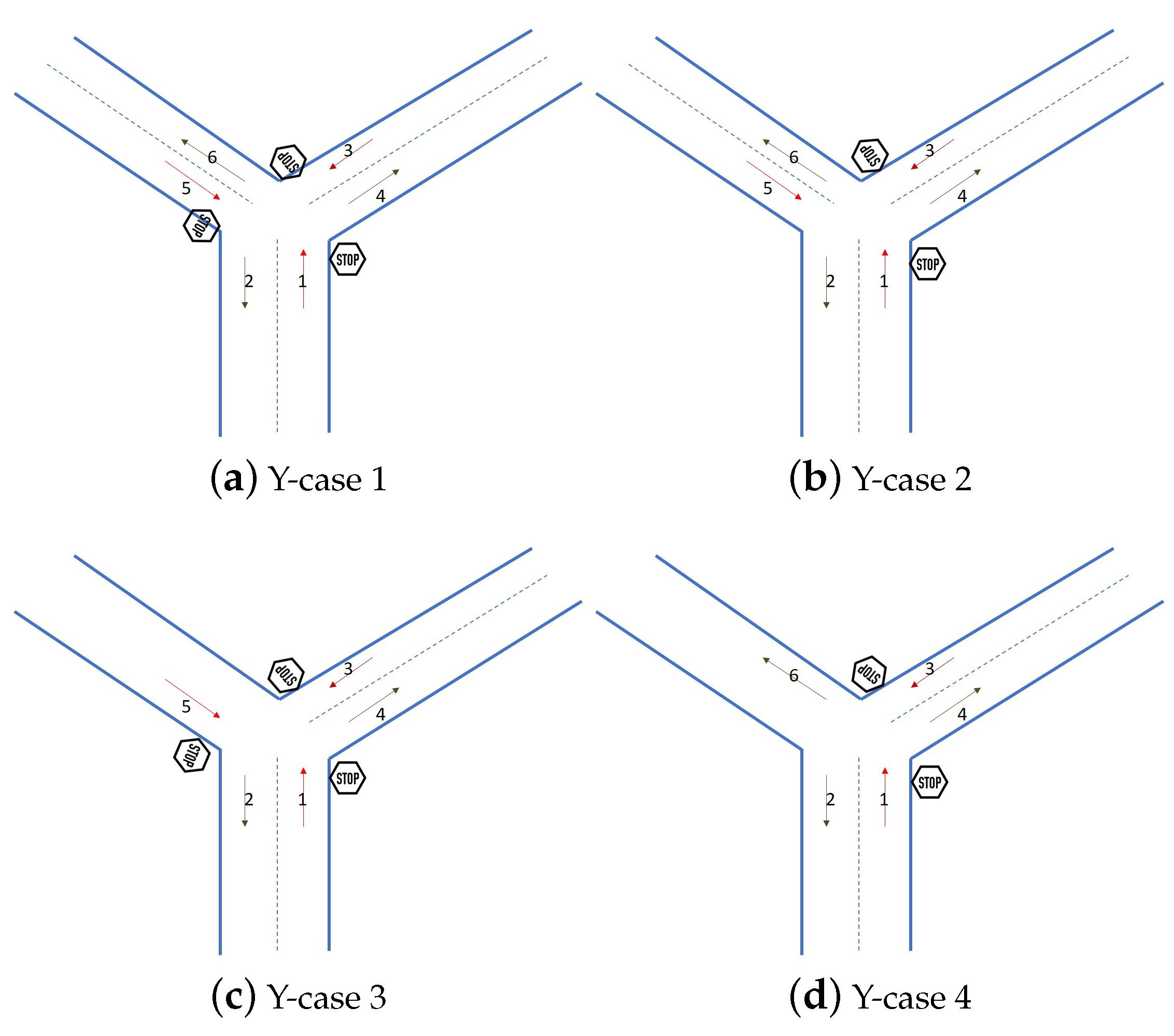
3.1.2. Y-Junction
In this junction, three roads meet at the shared point; the three roads have an equal size, coming at an acute or obtuse angle to each other. Only one of these roads can be in a one-direction design. Stop signs should be installed at all of the input traffic flows, or at least two of them.
Figure 2 illustrates four different cases of a Y-junction with stop sign installation. In
Figure 2a,b, all met roads are two-directional. Stop signs are used on all input traffic flows in
Figure 2a. In
Figure 2b, one of the input flows is set without a stop sign to obtain higher priority to pass through the road intersection without waiting. On the other hand, in
Figure 2c, one of the met roads is set only as input flow, and
Figure 2d illustrates the scenario when one of the met roads is set only as output flow. The required stop signs are illustrated clearly in
Figure 2.
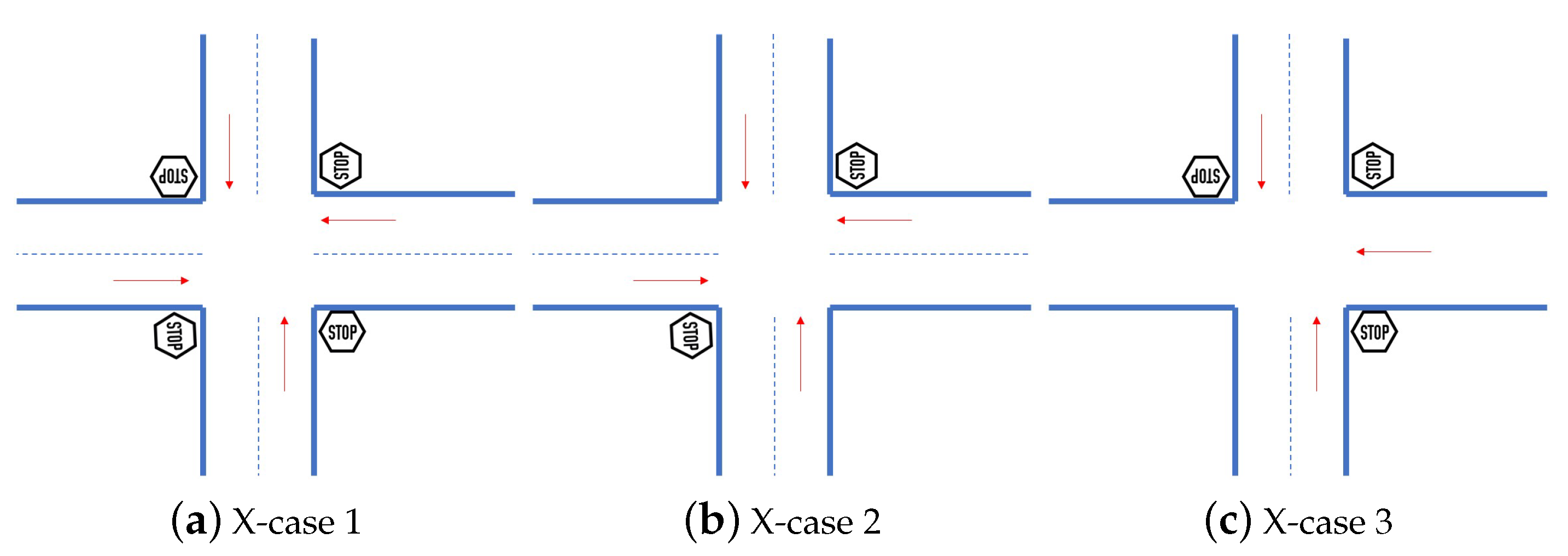
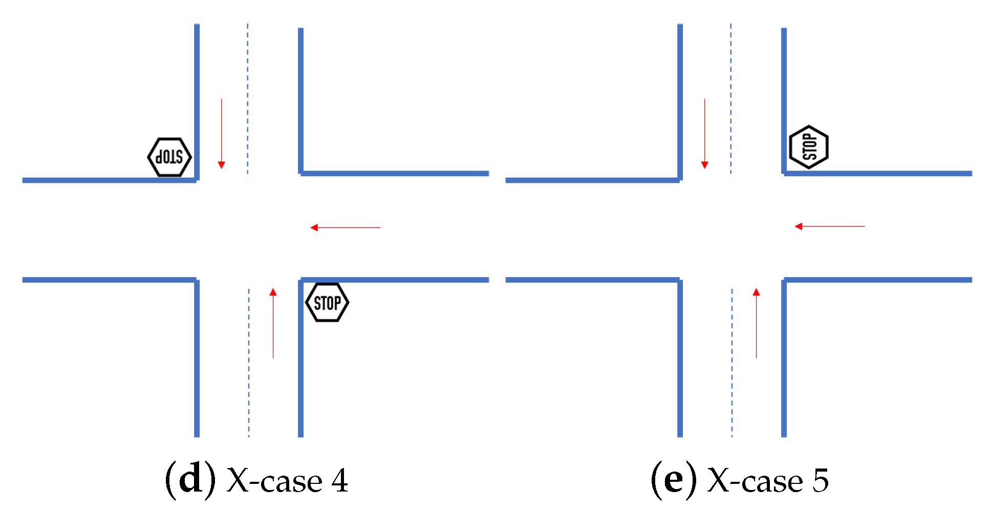
3.2. Four-Leg Road Intersections
Four-leg road intersections are created when two long roads cross at a certain point. The default and most appropriate design for four-leg road intersections is the crossed intersection (i.e., perpendicular roads). The X-junction is also an acceptable design where the skewed intersections are used, but the skew should be no more than 30
off perpendicular [
21]. Traffic lights usually control these intersections to guarantee safe and efficient sharing among the competing traffic flows. In light traffic scenarios for rural areas and small towns, stop signs are considered enough to control the competing traffic flows.
Stop signs can be installed on all input traffic flows and assign the same propriety for them to pass through the intersection. In other scenarios, when the main road crosses a secondary road, stop signs are only installed on the input traffic flows of the secondary road. This assigns higher priority for vehicles on the main road to pass directly through the intersection without waiting. The main and the secondary road can be designed in one- or two-direction traffic flows.
Figure 3 illustrates all possible scenarios for installing stop signs on four legs road intersections. In
Figure 3a,c, the stop signs have been installed on all input flows. However, in
Figure 3a, the two crossed roads are two-direction roads. In
Figure 3c, one of the two crossed roads is one-directional, while the other is designed in two-direction flows.
Figure 3b,d,e illustrate three different scenarios when a secondary road crosses the main road. The secondary road is a two-direction road in
Figure 3b,e, and it is a one-direction road in
Figure 3d.
4. Assisting Drivers around Stop Sign Intersection
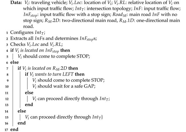
In this section, first, we summarize the driving rules and the priorities of passing through the stop sign intersections. Then, the successive steps of the intelligent proposed driving assistance protocol are presented in detail. The main assumption of the proposed protocol is using vehicular network technology to communicate among traveling vehicles and installed infrastructure (i.e., stop signs). Wireless transceivers are assumed to be equipped in these entities over the network. Moreover, cameras, GPS receivers, digital maps, and wireless transceivers are assumed to be installed on intelligent traveling vehicles in this protocol. These types of equipment are responsible of gathering the traffic data of the investigated area of interest. Algorithm 1 systematically illustrates the steps of the proposed protocol.
| Algorithm 1: Driver’s assistance protocol around stop sign road intersections |
![Futureinternet 15 00238 i001]() |
4.1. Driving Rules at Road Intersections Controlled by Stop Signs
We earlier investigated the various types of road intersections controlled by stop signs. From
Section 3, we can classify the stop sign road intersections into two scenarios. In the first scenario, a stop sign controls all input traffic flows at the intersection. The second scenario is where the stop signs are only installed on some input traffic flows, and others are left with no control [
22]. In both scenarios, the existing stop sign at any input traffic flow indicates that all arriving vehicles on that input traffic flow have to come to a complete stop before passing through the intersection. This allows the drivers to check the competing vehicles in the conflicting traffic flows and follow the driving priorities to traverse the intersection safely [
23].
The first vehicle that arrives at the intersection has the highest priority to proceed through the intersection among the competed vehicles (i.e., arriving from conflicted input flows). This means when each vehicle arrives at the intersection, its driver has to check its competed vehicles first. The arrival time of each competed vehicle determines which vehicle has arrived first. Then, the driver can determine the priority of passing through the intersection (i.e., if it can proceed directly or if it has to wait for other vehicle/s to proceed first). The time and speed to traverse the road intersection are controlled by the driver based on his/her skills and experience and according to the real-time traffic distribution on the road intersection.
On the other hand, arriving vehicles can proceed directly through the intersection without stopping if no stop sign exists on the contained traffic flow. However, if vehicles want to take the left direction at the intersection, they must come to a complete stop and ensure a safe gap between vehicles on the other main road before proceeding through the intersection [
22].
4.2. Driving Assistance Protocol at Stop Sign Intersections
This protocol provides real-time assistance to drivers to allow them to safely and efficiently traverse the stop-sign-controlled road intersections. First, it notifies the drivers early regarding the approaching intersections controlled by the stop signs. Then, drivers can start reducing their speed to stop at the targeted intersection smoothly. The time when the stopping vehicle can move through the signalized intersection is determined based on the arrival time of completed vehicles and the priorities of the driving rules. Finally, drivers must pass through the intersection at a suitable speed. These successive steps are presented in detail in the rest of this section.
4.2.1. Configuring the Intersection’s Topology and Stop Signs’ Distribution Case
The digital maps installed on the traveling vehicles notify the drivers early regarding the approaching stop sign intersections. The topology of the targeted intersection is matched to one of the three declared typologies (i.e., T-junction, Y-junction, and X-junction) in
Section 3. Then, the input traffic flows controlled by stop signs should be extracted to determine the traversed case of the signalized intersection.
The installed GPS in each vehicle determines its relative location to the targeted intersection. Accurate location results are obtained by the alignment of visual data with the installed digital map [
24,
25]. Vehicles arriving at the intersection from an input traffic flow free of a stop sign can pass directly through the intersection without stopping. This traffic flow is considered the main flow at the intersection. The main flow can be a unidirectional or two-directional flow. In T-junction and X-junction, when the arriving vehicle on the main two-directional flow aims to take the left exit on the intersection, it should stop and wait for a suitable gap on the other side. In case the main traffic flow is one direction, vehicles can pass through the intersection directly without stopping even for the left exit. However, in the Y-junction, the arriving vehicles on the main flow can proceed directly to the intersection’s right and left.
On the other hand, vehicles arriving at the intersection on a traffic flow controlled by a stop sign should come to a complete stop. This is regardless of the targeted direction of the vehicle on the investigated road intersection.
4.2.2. Recommending Smooth Stop
We assume that vehicles are equipped with the tools that allow them to accurately determine their speed and exact locations on the road network. The distance where the vehicles have to start reducing their speed and the deceleration rate is important for vehicles to stop smoothly. The longer the braking distance and the smaller the deceleration rate, the smoother the stop process at the targeted intersection. Drivers need to start reducing their speed earlier when they travel at a higher speed. Bringing the vehicle directly to a hard stop may lead to losing control.
The traveling speed, road slope, weather conditions, and road conditions affect the safe breaking distance and deceleration rate. Equation (
1) computes the safe breaking distance (
d) to stop in meters [
21]. This is based on the vehicle’s traveling speed (
V) and deceleration rate (
a). The measuring unit of vehicles’ speed is (km/h), and the deceleration unit is (m/s
2).
Each vehicle that arrives at a safe distance from the intersection is recommended to decelerate its speed smoothly. This is considering the average speed of vehicles on that traffic flow and the road’s conditions.
4.2.3. Passing or Waiting Decision
Stopping vehicles at the road intersection need to decide when to traverse the road intersection based on their priorities to move through it. Upon stopping at the targeted intersection, the first stopping vehicle
v has to capture its arriving time
. The first stopping vehicle in each input flow of the intersection keeps the
until it traverses the road intersection. Then, the next arrival vehicle sets the current
. In order to traverse through the shared road intersection, each vehicle
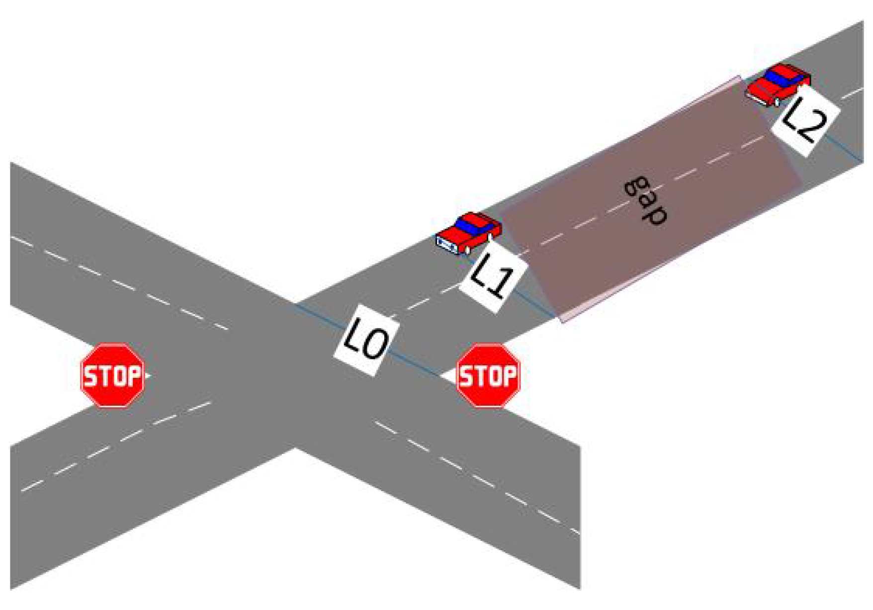
v stopping at the controlled road intersection has to check all the competing traffic flows. If any competing traffic flows are the main flow (i.e., has no stop sign), the vehicle has to stop waiting and sensing other vehicles on that main flow. This includes gathering the real-time location (
L) and speed (
S) of vehicles moving on the main traffic flow. Based on analyzing the locations and speeds of vehicles there, the gap distances between successive vehicles are determined using Equation (
2). Where
is the location of the road intersection,
is the location of the first vehicle (
) on the main flow,
is the location of the second vehicle (
) on the main flow,
is the speed
, and
is the speed of
. When a safe gap (i.e., the difference between the arrival times to the intersection of two successive vehicles is enough for a vehicle to traverse the road intersection safely) is detected on the main flow, the first arrival-conflicted vehicle can proceed through the road intersection.
Figure 4 illustrates an example of a four-leg road intersection, where a secondary road crosses the main road scenario. In this figure, the safe gap between two successive vehicles is illustrated by a red bounded box.
On the other hand, if the stop signs are installed on all input traffic flows of the road intersection, each vehicle V that arrives at the road intersection should save and announces its arrival time . Then, each vehicle checks its competing traffic flow to find the of the first vehicle in each flow. The first arrival vehicle has the highest priority to traverse the road intersection first.
4.2.4. Recommending Suitable Speed to Pass through the Intersection
We can see from the previous steps that any vehicle is recommended to traverse through a stop sign intersection in one of the following four cases:
Case 1: arriving at the intersection on the main traffic flow.
Case 2: arriving at the intersection on the two-way main road and aiming to take a left turn.
Case 3: arriving at the intersection on the secondary traffic flow and catching a safe gap between vehicles on the main flow.
Case 4: arriving first at an intersection that has stop signs at all input flows.
According to the case, vehicles are notified first about their eligibility to traverse the intersection. The best traveling speed to traverse the intersection depends on the case of the vehicle before traversing the intersection and the length of the path that the vehicle has to travel inside the intersection (). Moreover, the length of the safe detected gap between successive vehicles on the main road affects the required speed to traverse the intersection.
In the first case, vehicles should traverse the intersection smoothly without changing their speed. Vehicles in the second and third cases must control their speed to traverse the intersection within the safe gap period. Thus, Equation (
3) computes the average required speed (
to traverse the intersection in these scenarios. The vehicle has to accelerate from the stopping status (i.e., the speed is zero) to reach the
as fast as possible.
Finally, for the last case, the vehicles can move at any speed, with no restrictions except the speed limitation of the investigated road scenario. However, the faster they move, the more efficient the road intersection becomes in reducing the stopping delay time.
5. Performance Evaluation
In this section, we aim to study the performance of the proposed protocol. We first try to determine the affecting parameters. Then, we measure the protocol’s effectiveness in reducing accident rates and increasing the throughput of road intersections controlled by stop signs. Different typologies of road intersections are investigated in this study (i.e., T-intersection, Y-intersection, and X-intersection). These typologies are tested while considering to contain the main road and, in all ways, stop scenarios. Three main parameters are evaluated for each topology: breaking distance, accident rate, and the throughput of the investigated road intersection. These parameters are compared for the selected scenarios where the proposed protocol is used to assist the drivers (assist-used) and when it is absent (i.e., assist-absent). The accident percentage is computed in this work based on the possibility that two conflicted vehicles are met at the road intersection controlled by the stop sign. We assume that 20% of the vehicles arriving at the road intersection are not stopped in the assist-absent scenario.
Table 1 illustrates the used parameters in each tested scenario. SUMO [
26] was used to generate the mobility scenarios at the assumed road intersection. The tested experiments used different traffic densities (i.e., very low, low, medium, high, and congested). NS-2 [
27] was used to implement the proposed protocol. NS-2 is a discrete event simulator targeted at networking research. It can be used to support simulation for network-based applications. In these experiments, we assume that all vehicles are following the recommendations of the assistance protocol in the assist-used scenario.
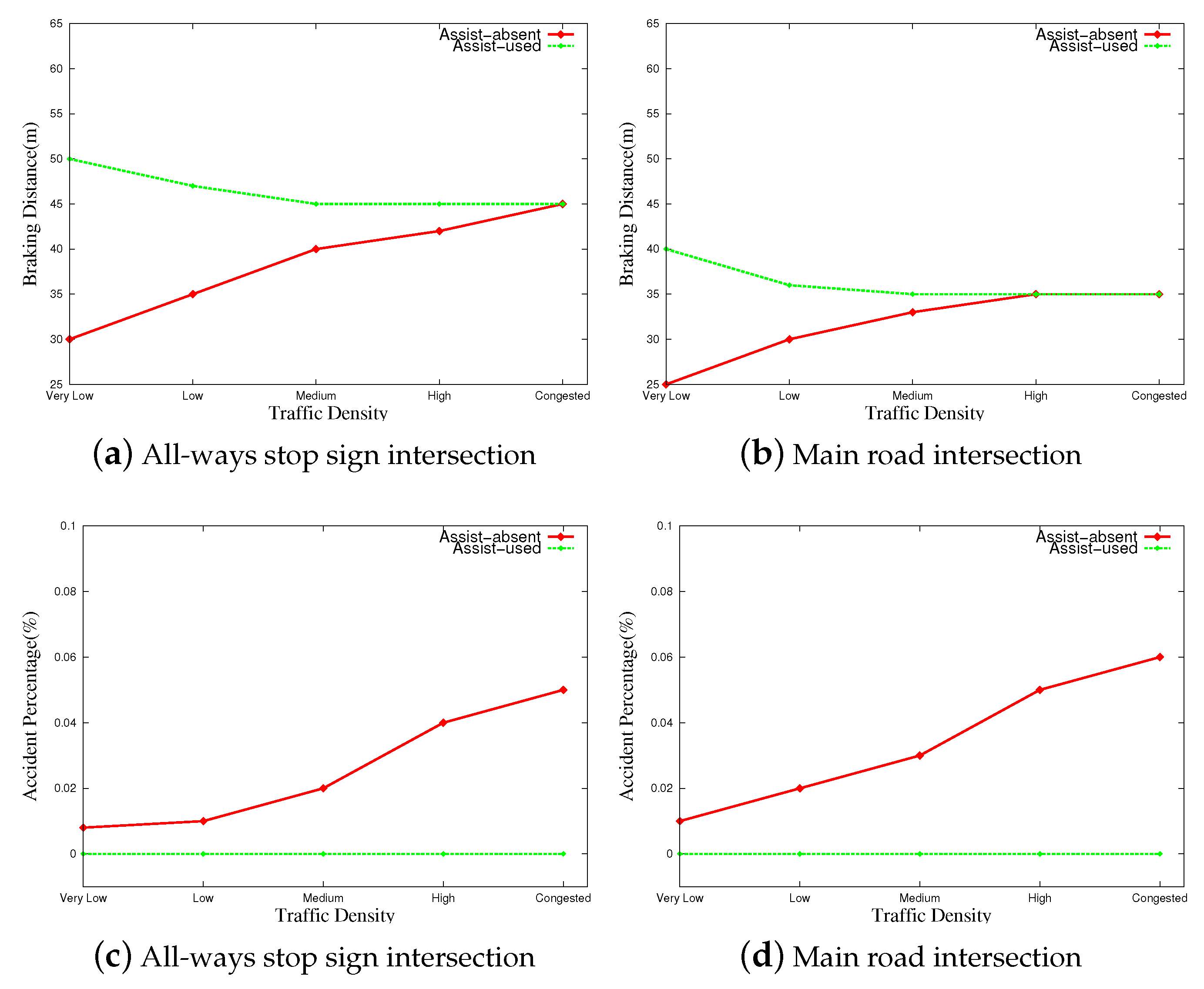
5.1. Performance Evaluation of the Proposed Protocol at T-Junction
In this section, the protocol is tested in two T-junction scenarios.
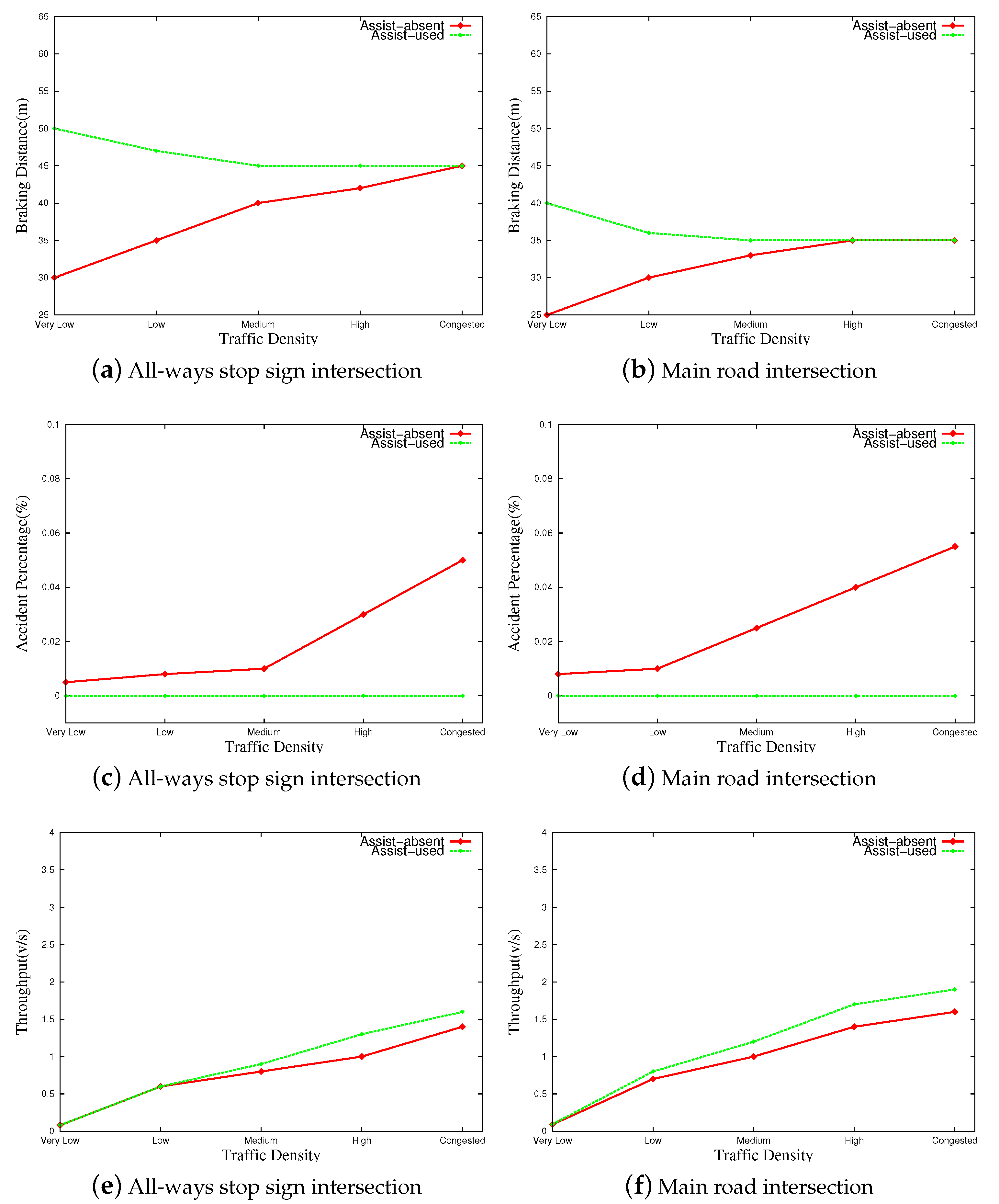
Figure 5 graphically illustrates the performance of the proposed protocol compared to its absence at T-junction stop-sign-controlled scenarios. The first scenario represents the case where stop signs control all input traffic flows. The second scenario represents the stop sign only being installed at the input flow of the short leg at the road intersection. We can see from
Figure 5a,b that the proposed protocol increases the braking distance of vehicles by 30% on average. This enhances the safety conditions on the investigated road scenario. The reduction rate in the breaking distance is decreased by increasing the traffic density in both scenarios. The same breaking distance is obtained in highly congested scenarios. The driving assistance protocol aims to recommend a suitable time to start reducing the speed (i.e., safe braking distance). This mainly depends on the traveling speed of each vehicle. Vehicles are forced to drive at low speeds when the density is high. Then, the safe braking distance is decreased to the minimum value when no assistance protocol is used (i.e., assist-absent). At the same time, the proposed protocol aims to find the safe value and compute it by Equation (
1) in the scenario where the proposed protocol is used. Both scenarios have agreed on the same safe braking distance. Fewer vehicles are stopping in the scenario where a secondary road crosses the main road. Thus, the braking distance is less in that scenario.
On the other hand, the accident rate is 10% more on the main road scenario compared to the all-ways stop signs, as appears in
Figure 5c,d, respectively.
Figure 5c represents the accident percentage for the all-ways stop signs intersection, and
Figure 5d represents the accident percentage for the main road intersection scenario. Comparing these two figures, we can see that for all traffic densities, the accident percentage on the all-ways stop sign intersection is 10% more than the acquired percentage on the main road intersection scenario. However, the assistant driving protocol completely eliminated accidents in both investigated scenarios.
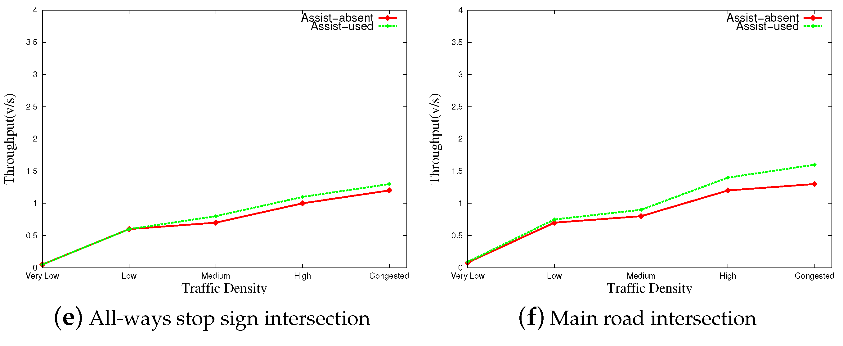
Finally, the throughput of the investigated road intersection was studied in this set of experiments. As we can infer from
Figure 5e,f, the proposed protocol (i.e., assist-used scenario) increases the throughput on both tested scenarios. The throughput of the main road scenario is higher than the all-ways stop sign scenario because many vehicles can proceed through the intersection without stopping.
5.2. Performance Evaluation of the Proposed Protocol at Y-Junction
The Y-junction is another three-leg road intersection scenario where the same size of angles exists between each two adjacent legs. The performance of this road scenario is close to the T-junction scenario.
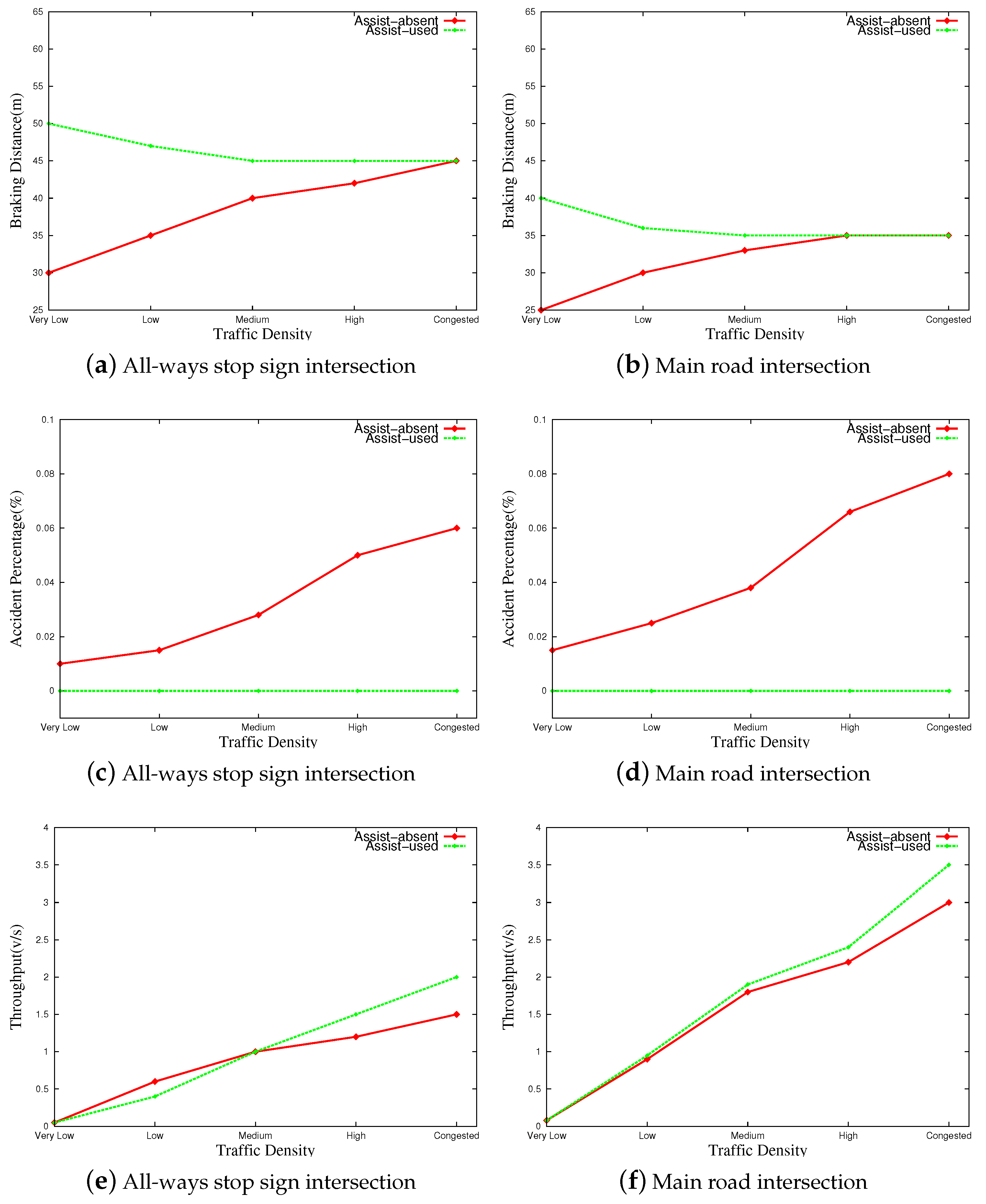
Figure 6 graphically illustrates the performance of the proposed protocol at all-ways stop signs and the main road crossing a secondary road. As we can see from
Figure 6c,d, the proposed protocol succeeds in increasing the braking distance of the stopping vehicles in both tested scenarios by 25% on average. This enhances the safety conditions, as discussed earlier. In the highly contested road scenario, the stopping distance is decreased to meet the average stopping distance of vehicles when the assistance protocol is absent.
The proposed driving assistant protocol eliminated accidents in the tested road scenarios.
Figure 6e,f graphically show the accident rates at the tested road intersections. The effects of the proposed protocol are higher in the congested road scenarios than in the low-traffic-density scenarios. In the latter scenario, the accident rate is originally low (i.e., 1%). Thus, eliminating it is a lower effect than in highly congested road scenarios since the accident rate is high (i.e., up to 6%) without using the assistance protocol.
Finally, from
Figure 6e,f, we can see that the proposed protocol increases the throughput of the investigated road Y-junctions by 10% on average. From these figures (i.e., e and f) we can also infer that a higher increase in the throughput is obtained at higher traffic densities. Moreover, the throughput of the main road intersection is higher than the throughput of the all-ways stop sign scenario.
5.3. Performance Evaluation of the Proposed Protocol at X-Junction
In this last set of experiments, we evaluate the performance of the proposed protocol at the most common road intersection (i.e., X-junction).
Figure 7 graphically illustrates the performance of the proposed protocol in the X-junction road intersection. The braking distance of stopped vehicles is increased using this protocol, and thus, the safety conditions are enhanced.
Figure 7c,d show that the stopping distance at low traffic density in both tested scenarios is highly increased compared to the high-traffic-density scenario for the same road intersection.
The proposed protocol completely eliminated the accident rates in the X-junction as well.
Figure 7e,f illustrate the performance of the proposed protocol in terms of average accident rates. In the scenario of assist-absent, the accident rates reached 6% and 8% in highly congested X-Junction road scenarios for the all-ways stop sign intersection and main road intersection scenarios, respectively. The proposed protocol (i.e., assist-used) successfully eliminated the accident rate in both scenarios.
The throughput of the investigated road intersection is significantly increased, especially for highly congested scenarios.
Figure 7g,h graphically represent the performance of the proposed protocol in terms of increasing the throughput of the investigated road intersection. We can also see from the figure that the throughput of the main road scenario is higher than the throughput of the all-ways scenario. This is due to the fact that vehicles traveling on the main road are not required to stop at the road intersection. However, on the all-ways stop sign intersections, all vehicles have to come to a full stop at the road intersection.
6. Conclusions
This paper proposes a driving assistance protocol to help drivers around road intersections controlled by stop signs. The protocol starts by configuring the architectural design of the road intersection. Then, the existence of the main road scenario is investigated. Each vehicle can determine its relative location to the targeted road intersection. The optimal braking distance and deceleration rate are recommended for each vehicle at the targeted intersection. This is according to braking distance mathematical models. After that, the vehicle is informed of the best time to proceed and the optimal traveling speed according to the driving rules and available gaps. This protocol was extensively tested through simulation in different road intersection scenarios. From the experimental study, we can infer that this protocol successfully extends braking distance by 25% on average. It enhances safety conditions and eliminates accidents at the investigated road intersections with the assumption that all vehicles apply the recommended instructions of the assistance protocol. Finally, the proposed protocol increases the road intersection’s throughput by 20% on average. It enhances general traffic efficiency over the road network.
In future studies, we plan to investigate other scenarios where pedestrians and cyclists are simulated on the tested road intersections. Other simulations of the road intersections that consider the parameters of arrival rate, compliance rate regarding a full stop, and speed profile will be considered. Moreover, the scenarios with noncompliance rates are going to be considered. Weather conditions, such as snow and heavy rain scenarios, on the safe stopping distance and traveling speed, are going to be considered in our future studies as well.


