1. Introduction
Global data traffic has experienced significant growth in recent years, and it is expected to continue increasing primarily driven by the emergence of groundbreaking 6G applications and services, such as augmented reality, holographic communications, and even more sophisticated AI applications, which will require stringent requirements in terms of data rate/bandwidth and latency having an impact in the evolution of optical networks [
1,
2]. This exponential growth will imply a change in terms of volume and distribution of traffic in the network, highlighting the importance of flexible, robust, scalable, reliable, and high-capacity optical networks [
3]. According to [
1], in the aggregation metro segment, the flow capacities from access nodes directed towards additional nodes, particularly regional nodes, are foreseen to escalate to a maximum of 2 Tb/s in the medium term and an impressive 8 Tb/s in the long term. According to the estimations derived from traffic analysis of [
1], regional and national nodes should efficiently manage the aggregated traffic, ranging from a few Tb/s in the short term, ten Tb/s in the medium term, and potentially reaching up to a hundred Tb/s in the long term. This underscores the need for robust and scalable infrastructure to accommodate the increasing demands on network resources over various time horizons from the access to the backbone network segments [
4].
The landscape of 6G networks will also see significant enhancements in the wireless segment [
5]. This includes more efficient wireless links that complement the wired infrastructure, providing seamless communication with final user devices enabling optical/wireless convergence [
6,
7]. The wireless segment for 6G is currently receiving high attention, and novel technologies such as THz, millilitre wave and visible light communications, integrated and free-space optics or power-over-fibre deployment as well as the use and adoption of machine learning techniques, softwarization and massive multiple-input multiple-output signalling are under active investigation to provide additional features [
7,
8,
9,
10,
11,
12,
13,
14]. Notably, there is a focus on incorporating high-accuracy positioning, imaging and sensing capabilities, which are expected to play an important role for enabling services for all verticals within 6G networks.
The integration/convergence of both wired and wireless technologies is essential to meet the diverse and demanding requirements of 6G applications and support the incoming traffic increase [
15]. The combination of high-capacity optical networks and advanced wireless links is crucial for ensuring the delivery of low-latency, high-throughput, and reliable connectivity. Moreover, as part of the evolution towards 6G, networks are anticipated to become more energy-efficient, contributing to the reduction in carbon footprints and aligning with global sustainability goals [
16].
In this context, key advanced technologies including multiband (MB) and spatial division multiplexing (SDM) have been recently investigated for evolving current optical networks towards enabling the expected network capacity scaling. MB technology enables the utilization of additional bands beyond C-band, such as E-, S-, L-, O- and U-bands, in order to increase the available bandwidth of the fibre and optical spectrum resources [
17]. This not only allows for the simultaneous transmission of data across various frequency bands, but also enhances the network’s resilience and flexibility. Additionally, SDM enables to further enhance overall network capacity and scalability by exploiting multiple spatial channels, which can be based on a bundle of standard single-mode fibres (SSMFs) or even speciality fibres such as multicore fibres (MCFs) and few mode fibres (FMFs) [
18,
19]. By exploiting spatial diversity, SDM provides an advance in network capacity, enabling optical networks to accommodate an ever-expanding volume of data traffic. Together, MB and SDM technologies are capable of addressing the scalability challenges presented by 6G applications and services [
20,
21]. Specifically, the convergence of these two advanced technologies is anticipated to shape the landscape of optical networks in the 6G era by achieving:
- (i)
Enhanced bandwidth and spectral efficiency: MB enables to maximize the spectral resources, allowing for efficient data transmission across a wide range of frequencies/bands, while SDM exploits the spatial dimension such as cores/modes, dramatically increasing the network’s capacity.
- (ii)
Enhanced network resilience and flexibility: by transmitting data simultaneously across various bands the systems will be more adaptable to dynamic network conditions. Additionally, the spatial diversity will also contribute to the resilience of optical networks. In the event of a failure in one spatial channel, the network can dynamically redistribute resources to maintain service continuity. Together, the convergence of MB and SDM technologies provides a comprehensive approach to fortifying optical networks against disruptions, ensuring robustness and adaptability.
- (iii)
Higher network scalability: Multiband over spatial division multiplexing (MBoSDM) technology addresses scalability challenges by efficiently utilizing available bandwidth across diverse bands and exploiting spatial diversity to increase network capacity. The combined effect of MB and SDM technologies is particularly relevant to meet the scalability demands and accommodate the ever-expanding volume of data traffic expected from the diverse range of applications and services anticipated in the 6G era.
Therefore, MBoSDM implies a transformation towards achieving unparalleled levels of efficiency, flexibility, and scalability in the 6G era harnessing the strengths of both technologies to address the evolving demands of data-intensive applications and services for the long-term period adoption within optical networks.
On this regard, the adoption of advanced transceiver architectures which can exploit MB and SDM technologies is fundamental in order to take advantage of the full potential of the networks. MB(oSDM) sliceable bandwidth/bitrate variable transceivers (S-BVTs) are proposed as an interesting transceiver option, based on a modular and scalable approach that can create a MB high-capacity flow that can be transmitted over different spatial channels [
22]. On the one hand, thanks to the transceiver modularity different building blocks can be enabled and disabled according to the network needs and traffic demand, enhancing network efficiency and flexibility. Specifically, this will allow network operators to dynamically allocate and adjust bandwidth and resources on-the-fly as needed. This flexibility maximizes the efficient use of available bandwidth, distributed to match the actual demand, reducing resource wastage and enhancing network performance. With the provision of transceiver scalability, additional slices/bandwidth can be added as necessary, ensuring the network can keep up with increasing demand. By enabling more dynamic and flexible network operation, sliceable transceivers can contribute to better network resilience. In the event of a failure in one slice, resources can be quickly redistributed to maintain service continuity. Finally, the efficient bandwidth utilization and the ability to scale as needed together with the possibility to adopt photonic integration approaches, that MB(oSDM) S-BVTs can offer, can lead to reduced power consumption and a smaller carbon footprint [
23,
24].
This work focuses on the design, implementation and experimental assessment of a MB(oSDM) S-BVT enabling up to 3 slices/flows within the C-, L-, and S-bands. The proposed transceiver approach exploits MB and SDM technologies and arises as a key solution to enhance overall network flexibility, efficiency, programmability and scalability toward meeting the stringent 6G capacity/bandwidth targets. In particular,
Section 2 provides an overview of MB and SDM technologies. Then,
Section 3 presents the MB(oSDM) S-BVT main architecture and key building blocks.
Section 4 includes a numerical analysis of the optical signal crosstalk (XT) to evaluate the impact in different bands, such as O-, E-, S-, C-, L-, and U-bands. Then, the proof-of-concept of the proposed transceiver is explained in
Section 5. The experimental assessment is performed in
Section 6, where MB and MBoSDM transmission systems are evaluated. Additionally, in-band and out-band XT evaluation is also performed. Finally, in
Section 7 the conclusions are drawn.
3. MB(oSDM) S-BVT Architecture and Definition
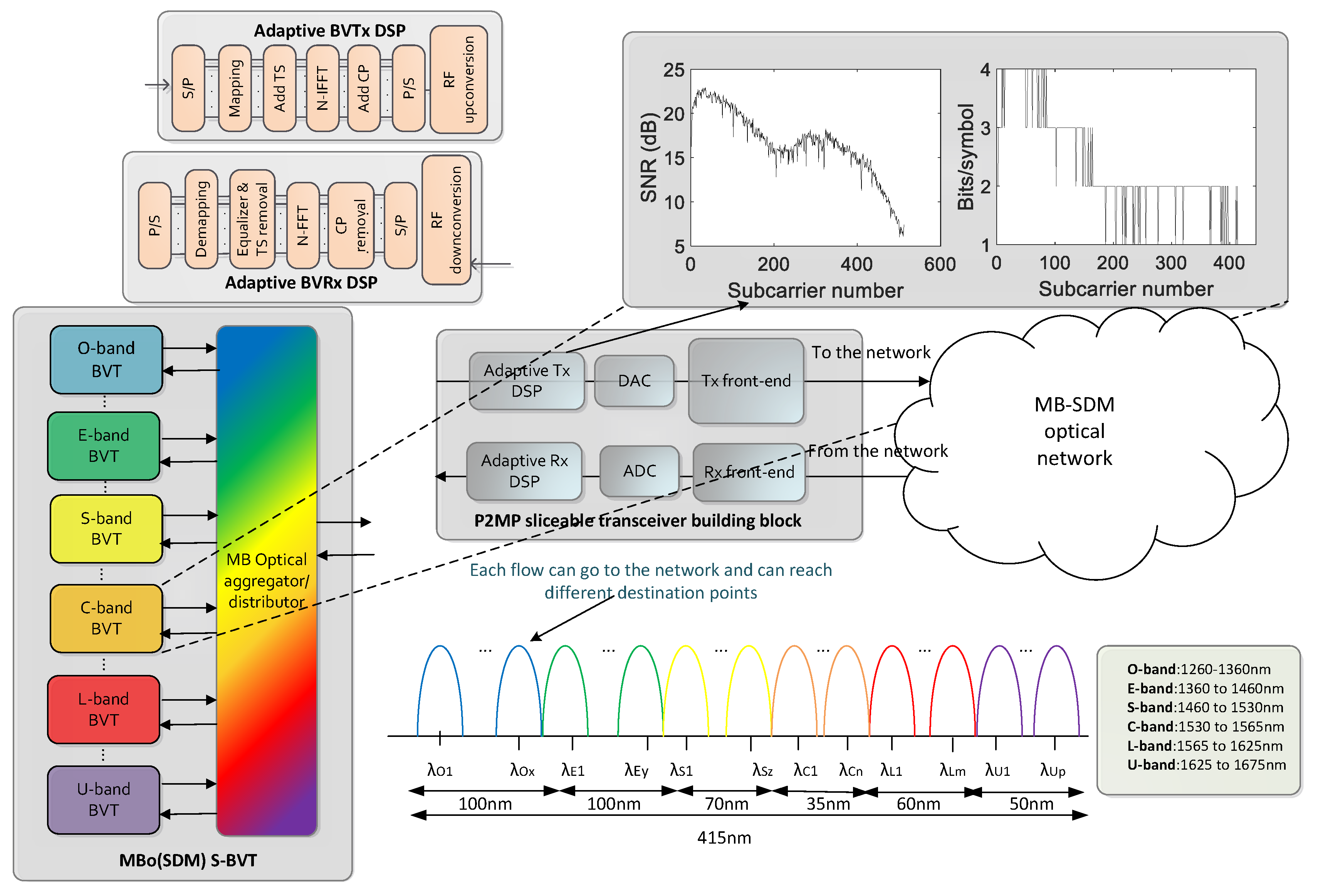
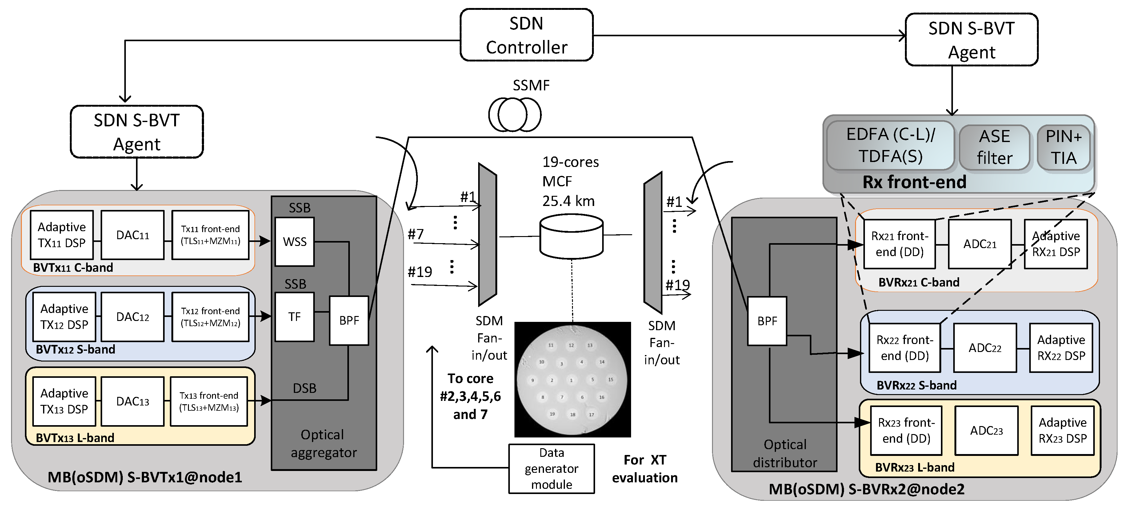
The proposed MB(oSDM) S-BVT architecture is depicted in
Figure 1 and it is based on multiple bandwidth/bitrate variable transceivers (BVTs) that can be enabled/disabled based on traffic demands, following a modular and adaptable “pay-as-you-grow” framework. The envisioned architecture also facilitates MB point-to-point (PtP) and point-to-multipoint (PtMP) connectivity, by incorporating several BVTs designed to operate across various transmission bands, such as C-, L-, S-, O-, U-, and E-bands, as depicted in
Figure 1. PtMP operation is achieved by the transceiver architecture’s ability to manage multiple BVTs concurrently, enabling multiple network destinations or end-points to be served with a single S-BVT. This capability is especially valuable in scenarios where diverse and evolving communication requirements exist among various network destinations, including variations in path length and data rate requirements [
38,
39]. Whether addressing varying transmission distances or accommodating different data rate requirements, the transceiver architecture seamlessly adapts to these diverse needs. This flexibility is key in scenarios where a central node needs to communicate with multiple remote locations, each characterized by unique communication parameters. In this context, the advantage of utilizing a single MB(oSDM) S-BVT for P2MP operations lies in its ability to streamline network infrastructure, reduce complexity, and enhance operational efficiency. Rather than deploying multiple transceivers to address individual communication links, the S-BVT optimizes resource utilization by managing multiple connections with a single, adaptable and programmable device. This not only simplifies the network architecture but also contributes to cost-effectiveness and ease of maintenance. Thanks to its scalable and modular architecture, it can easily accommodate the integration of new features and capabilities, thereby extending the useful lifespan of the equipment. At the digital signal processing (DSP) transmitter side of each BVT, adaptive loading based on orthogonal frequency division multiplexing (OFDM) is implemented, increasing the overall transceiver flexibility. Several operations are performed to generate the OFDM signals, such as data parallelization and mapping, insertion of training symbols (TS), implementation of the inverse fast Fourier transform, insertion of cyclic prefix (CP), serialization, and radio frequency (RF) up-conversion.
The implementation of bit and power loading (BPL) algorithms enable to dynamically adjust the power values and modulation format of each ODFM subcarrier to the specific profile of the channel, as depicted in
Figure 1 [
22]. This not only enhances the versatility of the transceiver, but also contributes to enhancing its overall performance. In the inset of
Figure 1, it can be seen an example of the BPL operation, considering a C-band BVT based on intensity modulation (IM) and direct detection (DD) in a back-to-back (B2B) configuration, which assigns high modulation formats to the subcarriers that present highest performance/SNR. After DSP, digital-to-analogue conversion by means of a digital-to-analogue converter (DAC) is performed to generate an analogue OFDM signal. Different configurations can be adopted at the transmitter front-end of each MB S-BVT building block for modulation of the MB OFDM signals, such as IM, amplitude modulation or even IQ modulation [
40]. Additionally, either external modulation (i.e., adopting Mach–Zehnder modulators—MZMs—and tuneable laser sources—TLSes) or direct modulation (i.e., using vertical cavity surface emitting lasers–VCSELs) can be adopted, trading-off performance versus cost/power consumption [
22,
41,
42]. Finally, the different contributions are aggregated/distributed by means of an optical aggregator/distributor capable to allow operation across all the considered bands. This device is a key element of the MB S-BVT architecture, that can be based on programmable filters capable to aggregate/disaggregated different MB slices [
43]. However, due to low level of maturity of this technology, alternative solutions based on static/non-reconfigurable band pass filters (BPFs) can be considered. The receiver of the proposed MB S-BVT can be based on different implementations, such as DD or coherent detection, trading-off performance versus complexity/cost [
22,
42]. Analogue-to-digital converters (ADC) are included in the transceiver architecture to digitize the OFDM analogue signal, to perform the receiver DSP operations. These include RF down-conversion, data parallelization, CP removal, fast Fourier transform implementation, equalization, symbol de-mapping, and serialization. The presented sliceable architecture will enable to dynamically allocate its available MB bandwidth into smaller, independently manageable contributions, that can also be transmitted through different fibre spatial channels (i.e., fibre cores, modes) enhancing overall flexibility, scalability, and providing an efficient utilization of the MB and spatial resources. Thanks to the transceiver modularity and sliceability the MB flow can be disaggregated in an intermediate network node to transmit different set of bands/sub-bands, corresponding to different users/slices, to different fibre cores and destinations. The available MB and spatial resources can be dynamically adjusted and reallocated as needed, and the different contribution of the MB S-BVT can be sliced to different users or applications based on their specific requirements. Hence, capacity and performance will be maximized, leveraging the spatial and frequency domains, while meeting the diverse needs of various users and services. On the top of that, the adoption and implementation of a software defined networking (SDN) control plane and the corresponding SDN agents will be crucial to successfully adapt and configure the proposed transceiver solution [
40].
4. Numerical XT Evaluation
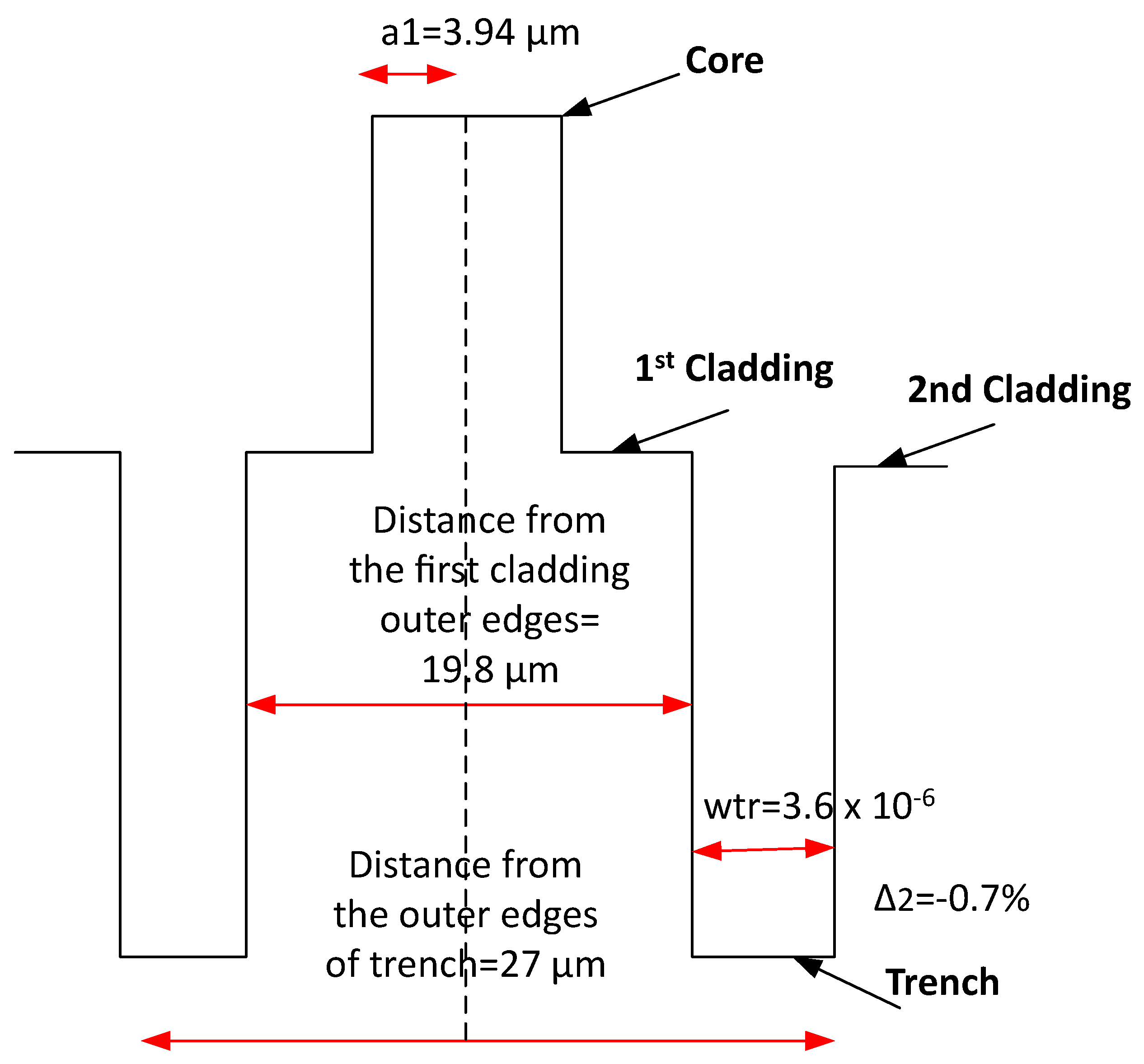
MCF transmission arises as a promising SDM technology that can provide increased capacity, efficient use of space, high scalability, simplified network architecture, redundancy, reliability and energy efficiency, by the enabling of data transmission through different cores within the same optical fibre. However, XT can occur when signals from one core interfere with signals in adjacent cores. This interference can significantly degrade signal quality and network performance, and presents a dependence with frequency/wavelength. Hence, a proper design and signal isolation techniques are necessary to mitigate this issue, to achieve low XT levels between neighbouring cores. One effective technique to reduce the XT levels in MCFs is to employ a refractive index trench in the fibre design. A refractive index trench is a modification in the refractive index profile of the optical fibre, by forcing a trench or a low-index region around each core to effectively isolate the cores from one another. This can be strategically used to minimize XT between adjacent cores, as the refractive index trench acts as a barrier between the cores, preventing the leakage of light from one core to the neighbouring cores and hence enhancing the overall signal quality and reliability.
The refractive index trenches can be a powerful tool for reducing XT in MCF, and their design and implementation require careful engineering and optimization. As an example,
Figure 2 shows the trench-assisted core design of 19-cores
km MCF considered for the experimental assessment in
Section 6. In this context, the mean XT value of a core can be approximated through evaluating a straightforward analytical formula [
44]. In fact, the homogeneous core single mode 19-core MCF is designed to achieve XT values between neighbouring cores of
dB, at 1550 nm, for a length of
km and a bending diameter of 159 mm. Hence, the impact of XT in different transmission bands can be numerically evaluated, also including the structural parameters and specifications of the 19-cores MCF of L =
km considered for the experimental assessment in
Section 6. Specifically, the XT can be approximated through the following equation:
where
is the core pitch (
= 34
m),
is the mode linear coupling coefficient between two neighbouring cores (defined in Equation (
2)),
=
cm is the bending radius, and
is the propagation constant. The propagation constant is defined as:
= (2
)/(
), being
the wavelength of operation and
the core effective refractive index. The mode linear coupling coefficient in trench-assisted structures can be calculated considering the following equation:
From Equation (
2) and considering the approximations and simplifications in [
44],
With a relative refractive index difference of
,
and (
) can be approximated as linear functions of
, being
=
, according to [
44]. Specifically,
,
,
is the core refractive index (
=
),
is the core radius and
is the trench width, as shown in
Figure 2. Finally,
is the modified Bessel function of the 2nd kind with 1st order and
, being
.
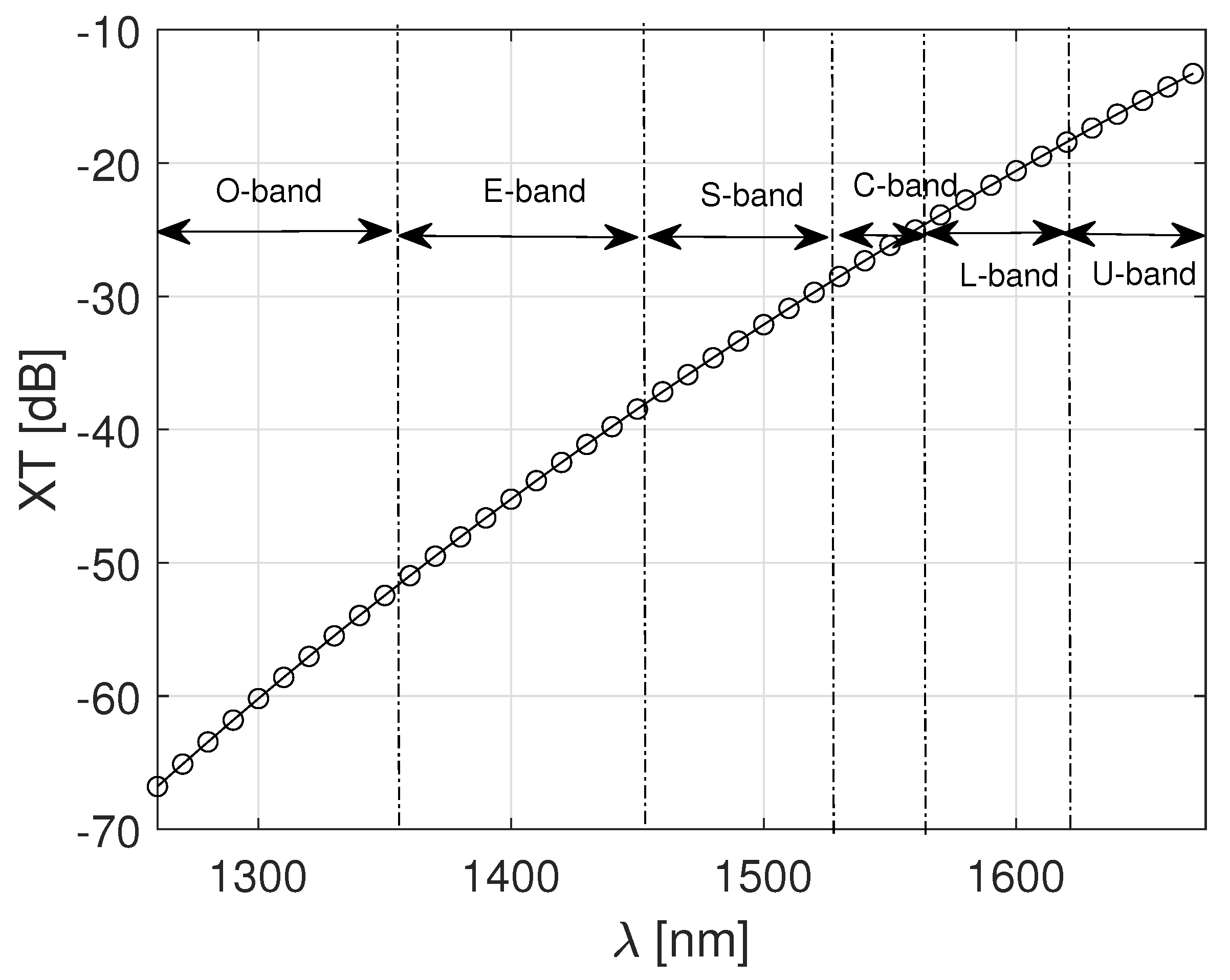
Following this analysis, the estimated XT per wavelength is depicted in
Figure 3. A range from 1260 nm to 1675 nm—covering the whole of the O-, E-, S-, C-, L-, and U-bands [
26]—has been taken into account. From the figure, it can be seen that the O-band is the spectral band less affected by the XT, presenting values below
dB, whereas within the C-band, the XT values range between
dB and
dB. In particular, at
nm the XT value is
dB, which perfectly match the measured XT mean value of the MCF specifications of
dB. Finally, the U-band presents a higher XT degradation, presenting values higher than −20 dB.
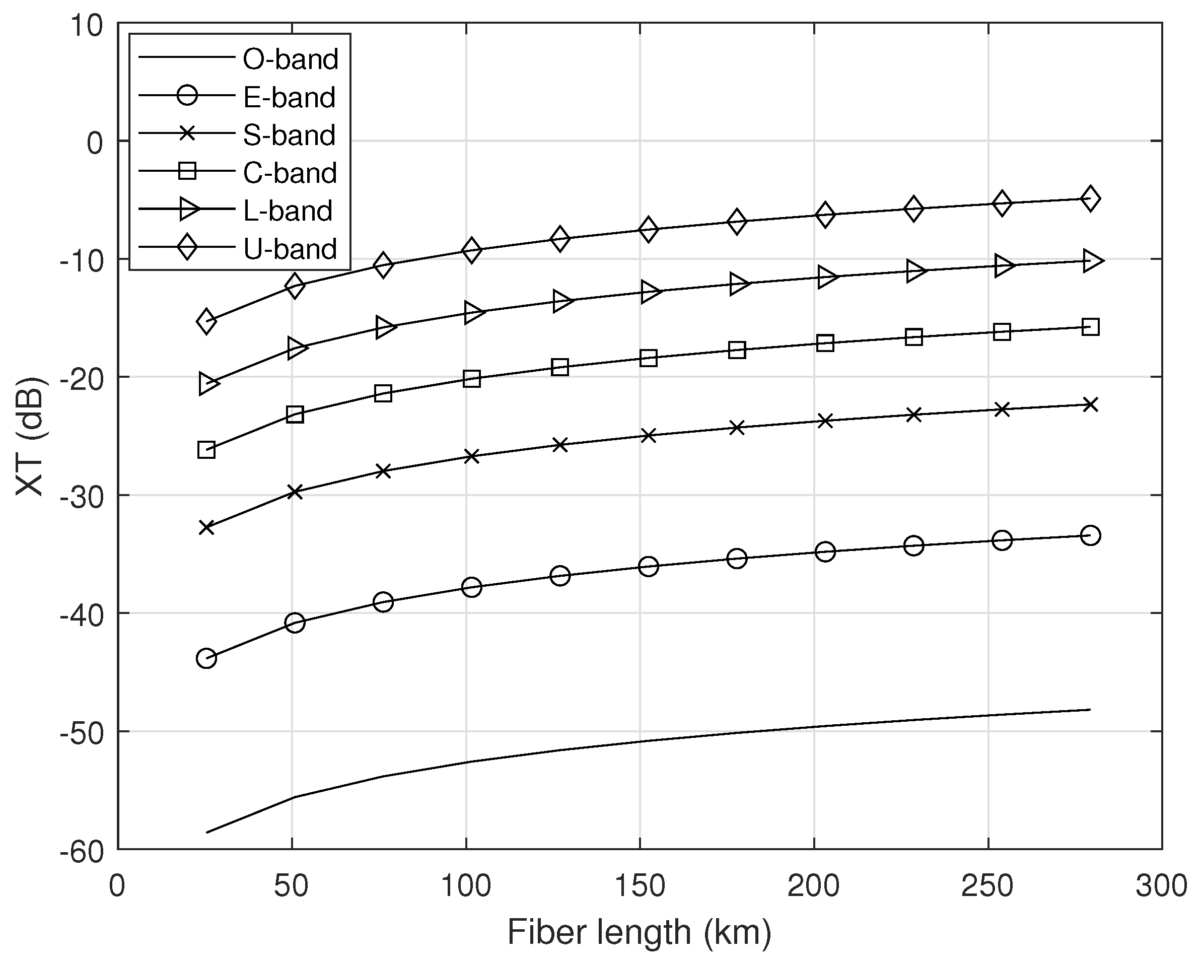
Figure 4 presents an evaluation of the XT considering different MCF lengths up to
km, corresponding to 11 spans of
km. In this particular scenario, central wavelengths of the different analysed bands are considered to perform the XT analysis: specifically, 1310 nm (O-band), 1410 nm (E-band), 1495 nm (S-band), 1550 nm (C-band), 1600 nm (L-band), and 1650 nm (U-band). The achieved numerical results show an increase in the XT effect at the increase in the MCF length. As it is also seen in
Figure 4, the U-band presents higher XT impact, showing values from
dB (after
km) up to
dB (after
km). After the maximum analysed MCF length of
km,
dB,
dB,
dB,
dB, and
dB are measured at O-, E-, S-, C-, and L-bands, respectively.
5. Setup Implementation and Proof-of-Concept
For the proof-of-concept assessment of the MB(oSDM) S-BVT, 3 different slices working at the S-, C-, and L-bands are enabled, as depicted in
Figure 5. Specifically, adaptive modulation based on the Levin–Campello loading algorithm is performed at each transceiver building block, to flexibly adapt the modulation format and power value per subcarrier according to the channel profile [
22]. After performing the different DSP operations described in
Section 3, a high-speed DAC at 64 GSa/s is used to generate an OFDM electrical signal of 512 subcarriers and 20 GHz bandwidth. The transceiver front-end is based on external modulation and includes an array of lasers, that can be set up within the S-, C-, and L-bands, and MZMs working at the quadrature point. In particular, an electro-absorption modulated laser (EML) set to 1500 nm is used for the S-band contribution with 150 kHz linewidth. 2 TLSes at
nm and 1600 nm are used for the C- and L-bands with linewidth values
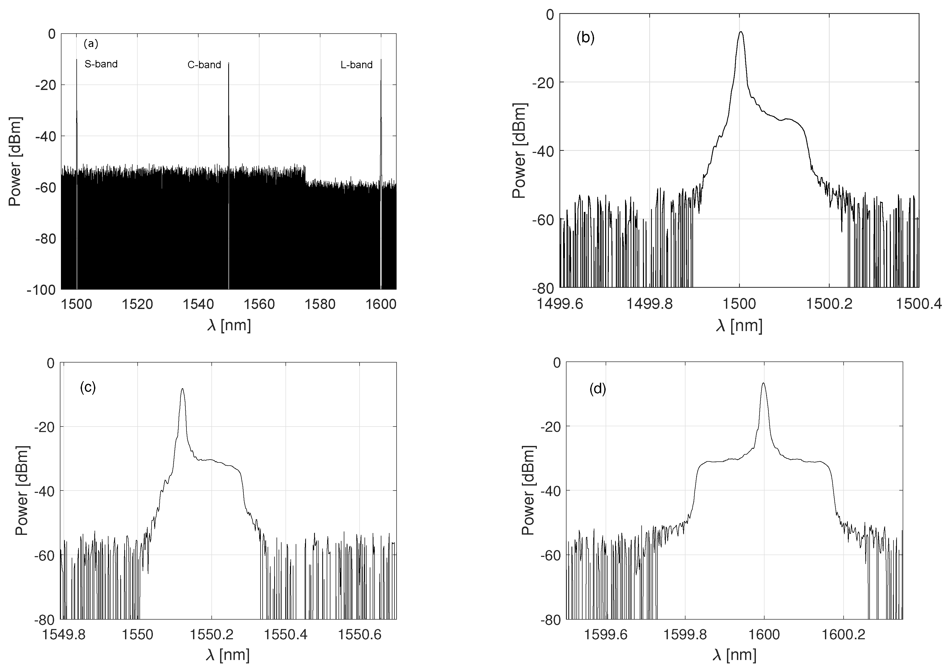
KHz and equal to 500 kHz, respectively. The output power of the three contributions are set to 10 dBm. A MB high-capacity flow is created by means of an optical aggregator, which includes single side band (SSB) filters and a BPF. SSB modulation is implemented within the C- and S-band slices, by including a wavelength selective switch (WSS) of 25 GHz bandwidth and a tuneable filter (TF) of 30 GHz bandwidth, respectively. This increases the resiliency against chromatic dispersion, enhancing overall performance. However, due to laboratory/setup limitations, the L-band contribution is not filtered and a DSB signal is aggregated with the other contributions. The transmitted MB high-capacity flow can be seen in
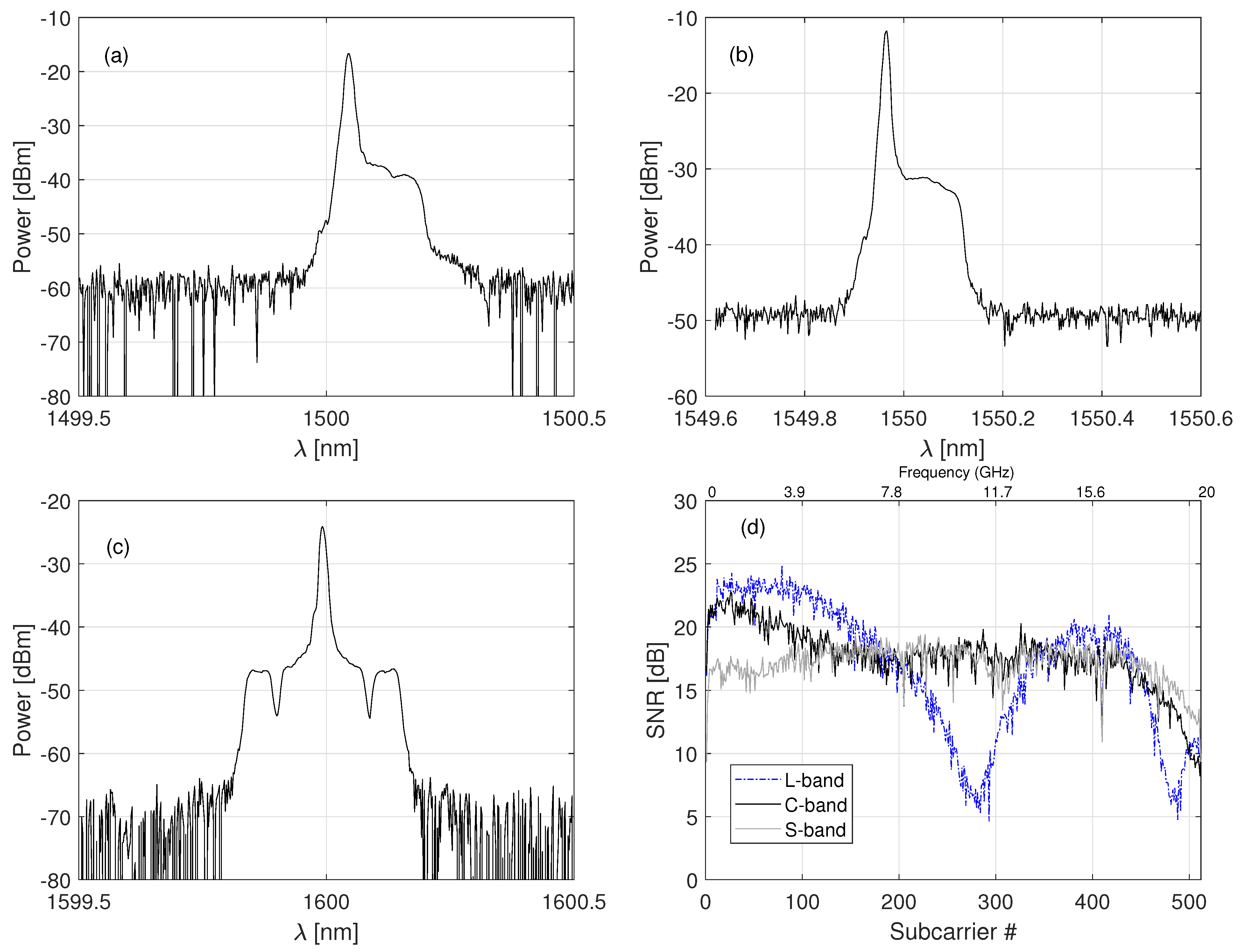
Figure 6, as well as the detailed S-, C-, and L-band spectra.
At the receiver side of the proposed MB(oSDM) S-BVT, an optical distributor is included, based on a BPF. The different slices are distributed to the corresponding bandwidth/bitrate variable receivers (BVRxs), adopting specific components/technology capable to operate in a particular band. Specifically, an EDFA (operating at automatic power control mode) and a WSS for amplified spontaneous emission (ASE) noise filtering (centred at
nm and 50 GHz bandwidth) are used at the receiver front-end, for the C-band contribution. The S-band slice is amplified with a TDFA (operating at automatic current control mode) and filtered with a static filter, whereas an EDFA (operating at auto current control mode) and a static filter are considered at the L-band. All the contributions are photodetected with different PINs and ADC converted with an oscilloscope at 100 GSa/s. Additional DSP and performance parameters (summarized in
Table 1) have been considered for the experimental assessment of
Section 6.
6. Experimental Assessment
This section summarizes the main achieved results of the analysis and assessment of the proof-of-concept of the MB(oSDM) S-BVT. We have targeted two different scenarios/use cases to assess the different capabilities and operation modes of the proposed transceiver, for both MB and MBoSDM transmission. For MB transmission assessment, the generated MB (S+C+L) high-capacity flow is transmitted over different fibre spools of G.652D SSMF up to 75 km [
45]. The SSMF, presents a CD coefficient of 17 ps/(nmkm) at 1550 nm and a mode field diameter (MFD) in the range of 8.6–9.2
m at 1310 nm. In this particular scenario of assessing MB transmission, the data generator module of
Figure 5 is not activated. Additionally, a 19-cores MCF of
km is considered to assess the MBoSDM transmission. The MCF has a MFD >7.88
m, corresponding to the fibre core diameter. The MB signal (S+C+L) is transmitted over core #1, whereas the adjacent cores (# 2, 3, 4, 5, 6, and 7) are filled with alternative data signals generated to evaluate both the in-band and out-band XT, as it will be explained and detailed later in this section. The alternative data are created by enabling the data generator module of
Figure 5 to fill the adjacent/neighbouring cores of the MCF with data to evaluate the XT effect. In the following experiments we consider that each fibre core can support the transmission of all bands and each band can convey different user data.
6.1. MB Transmission Assessment
In a first use case, MB transmission is assessed considering the experimental setup described in
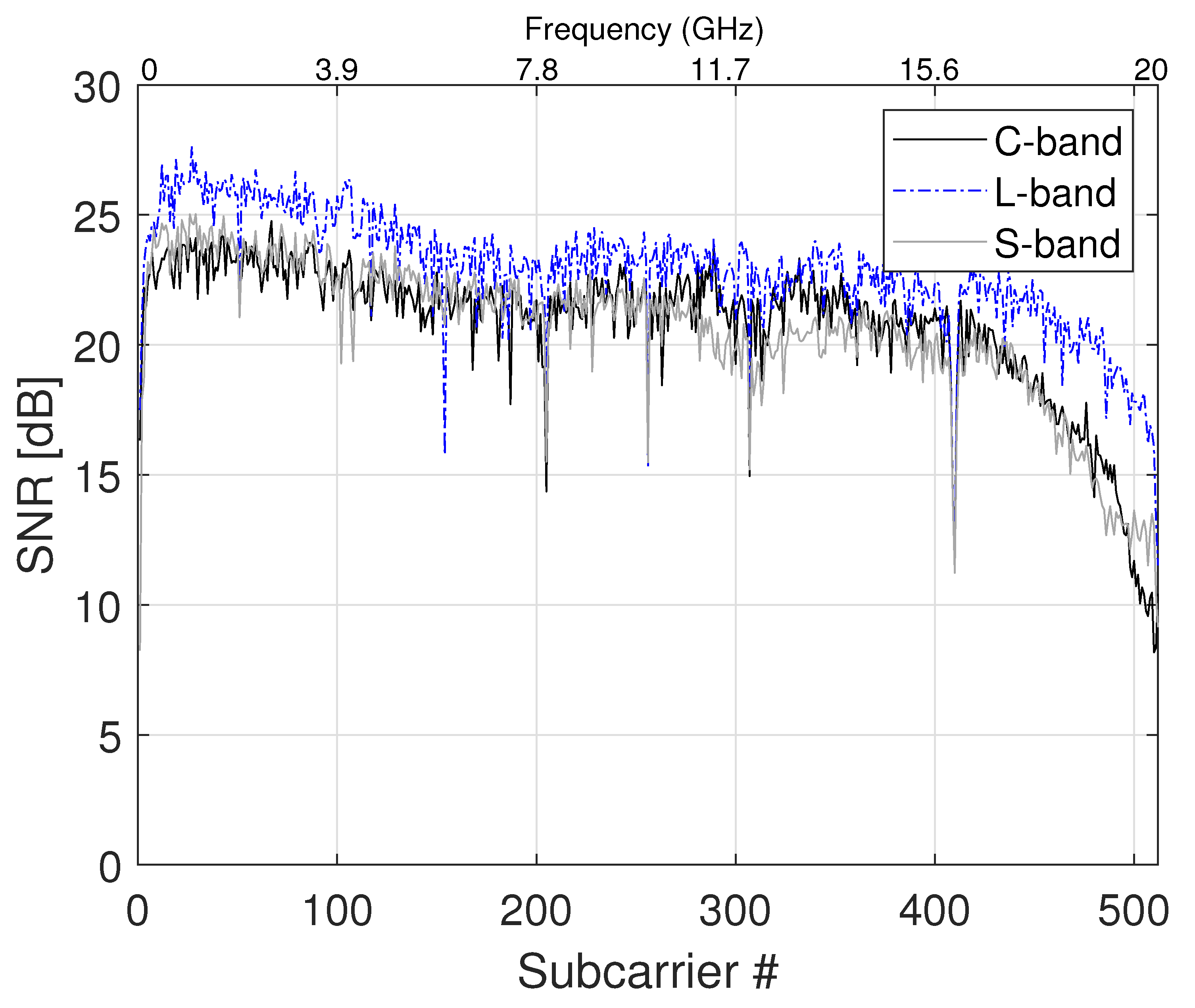
Section 5. The signal–noise ratio (SNR) profiles in a B2B configuration are depicted in
Figure 7. From the figure, it can be seen that the three slices, working in different bands, present similar performance in terms of SNR per subcarrier. Mainly, the degradation of the higher frequencies, corresponding to the higher subcarrier numbers, is due to the limited bandwidth of the DAC, which is around 13 GHz bandwidth. In particular, the electrical OFDM signal occupies 20 GHz bandwidth, corresponding to 512 subcarriers. Considering a SSMF path of 25 km length, the SNR profiles present different performance per each band, as seen in
Figure 8d. The DSB L-band contribution is more affected by CD, showing two attenuation peaks within the signal bandwidth at around 11 GHz (subcarrier 281) and 19 GHz (subcarrier 488). This translates to a CD coefficient of
ps/(nmkm) at 1600 nm, according to Equation (
4):
D is the dispersion coefficient parameter,
c the speed of light and
the
n-th attenuation peak due to CD. The C- and L-band contributions are more resilient against CD, due to SSB modulation showing a flatter SNR profile. However, they present lower SNR values within the lower frequencies/subcarriers due to the setup implementation. In particular, different lasers, filter and amplification technology are used to set up the 3 BVTs conforming the MB S-BVT. BPL is applied to compensate the SNR degradation that specific subcarriers present in order to ensure the transmission at the target BER.
The received spectra after amplification and applying BPL are depicted in
Figure 8. From the DSB L-band spectrum, depicted in
Figure 8c, it could be seen that the implemented BPL algorithm has set to 0 the subcarriers with lower SNR. The SSB C-band and L-band spectra, in
Figure 8a,b, show 5 dB power attenuation due to fibre transmission over a 25 km path in comparison with the B2B spectra of
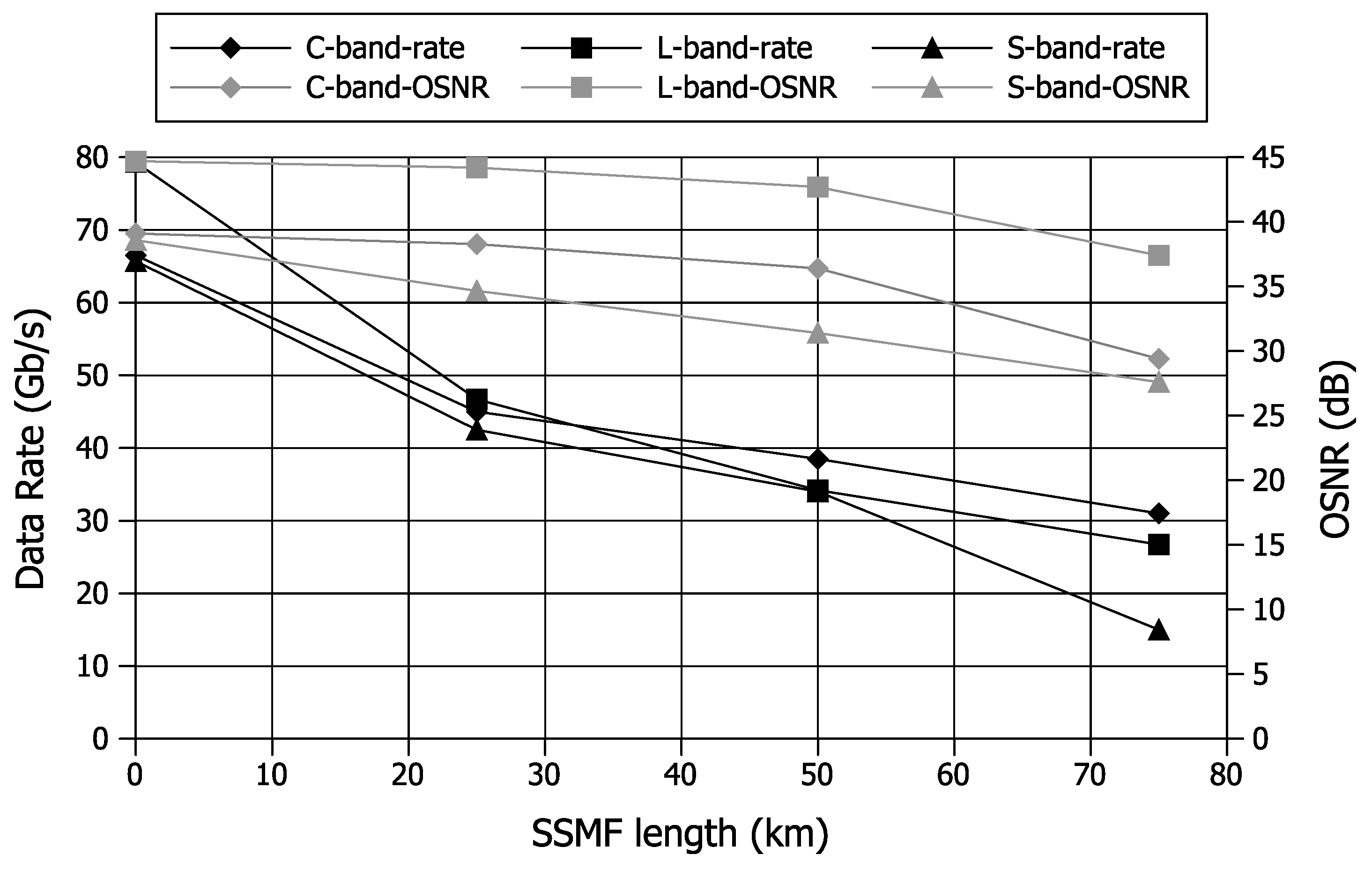
Figure 6. The achieved performance in terms of maximum data rate is depicted in
Figure 9, for different SSMF lengths. In the B2B configuration, an aggregated capacity of 212 Gb/s is achieved ensuring the target BER. After 25 km SSMF, this data rate decreases to 134 Gb/s, and thanks to the implementation of BPL algorithms, the 3 contributions still present similar performance. After 50 km and 75 km path, the aggregated capacity decreases to 107 Gb/s and 73 Gb/s, respectively. Due to setup implementations, the L-band contributions can achieve higher OSNR values. However, the DSB transmission is more affected by CD. This effect can be seen in terms of achieved data rate in
Figure 9, where the C-band contributions outperforms L-band contribution after transmission over the fibre with lower OSNR values.
Regarding the transceiver scalability, the modular architecture of the MB(oS-BVT) S-BVT enables the use of more slices in the different bands, in order to enable higher capacities. Specifically, by considering the full population of the analysed bands with 25 GHz (S+C) and 50 GHz (L-band) channel bandwidths, a total aggregated capacity of 47 Tb/s is envisioned in B2B configuration. This corresponds to 23 Tb/s for the S-band (350 channels), 12 Tb/s for the C-band (175 channels), and 12 Tb/s for the L-band (150 channels).
6.2. MBoSDM Transmission Assessment
A second experimental assessment is performed for the MBoSDM transmission, as a key scenario to provide the required capacity scaling expected in future networks. Hence, a 19-cores MCF of
km is considered in the setup of
Figure 5 to evaluate the performance of the proposed MB(oSDM) S-BVT. The total optical power of the C-, L-, and S-bands optical signals launched into the MCF fibre, measured in the optical spectrum analyser (OSA), is
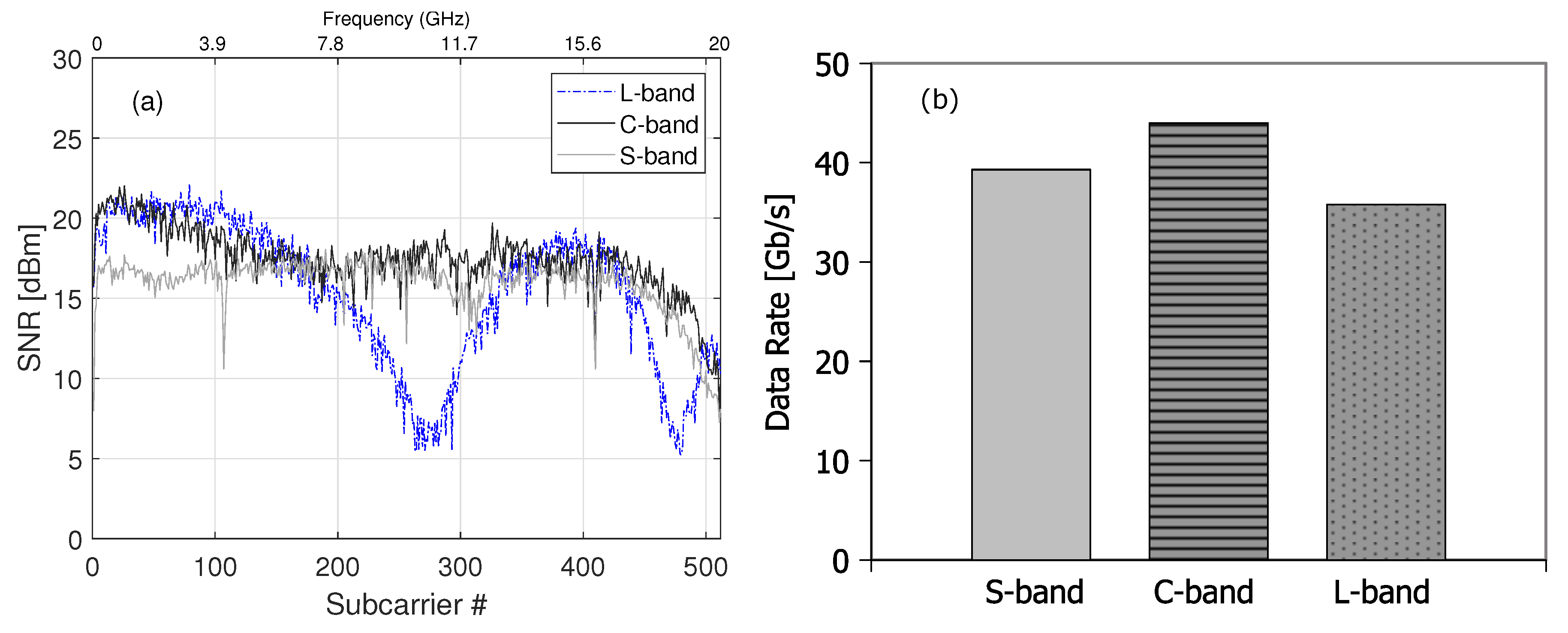
dBm. In this particular scenario, the estimated SNR profile per subcarrier is depicted in
Figure 10a, showing the CD impact on the DSB L-band contribution. Specifically, the first attenuation peak due to CD appears at
GHz corresponding to a CD coefficient of
ps/(nmkm) at 1600 nm, according to Equation (
4). Additionally, a degradation in terms of SNR is shown when comparing with the SSMF path of 25 km, depicted in
Figure 8d. In fact, for this particular length the MCF presents higher attenuation values per core, of up to 10 dB (measured within the C-band), with respect to the 5 dB attenuation within the SSMF. A first assessment is performed without considering the XT. In this particular case, the achieved capacity per band after transmitting over the MCF is shown in
Figure 10b. From the figure, it can be seen that the C-band contribution achieves the highest data rate of 44 Gb/s at the target BER and 36 dB optical signal noise ratio (OSNR). A capacity of
Gb/s (L-band) and
Gb/s (S-band) is obtained at
dB OSNR and
dB OSNR, respectively. In fact, when transmitting across the MCF, different performance per band is expected due to the wavelength dependence of fibre properties, such as effective area, CD and fibre attenuation/loss.
Thanks to the exploitation of SDM, spatial dimension can be also considered and new resources are available to further scale overall network capacity. A full population of the S+C+L-bands with a single core of the 19-cores MCF will envision data rates of Tb/s for the S-band (350 channels), Tb/s for the C-band (175 channels) and Tb/s for the L-band (150 channels). Hence, considering S+C+L bands and the 19 cores, the aggregated capacity can scale up to 500 Tb/s ( Tb/s).
Out-Band and In-Band XT Evaluation
Here, the out-band and in-band XT are evaluated using the data generation module of
Figure 5, which feeds the adjacent cores (
, and 7) of the MCF. In particular, for the out-band XT assessment, the data generation module consists of the S-band amplified contribution after the MCF. The S-band amplifier (TDFA-based) pump laser diode (LD) current is varied in steps of 100 mA up to a maximum value of 500 mA, to evaluate the impact of the out-band XT within the C-band and L-band. However, similar capacity of about 38 Gb/s is obtained in all the analysed cases, as the OSNR slightly varies around 34 dB. This translates to 6 Gb/s data rate decrease in comparison with the scenario that not considers XT, where 44 Gb/s was achieved at 35 dB OSNR. In the case of L-band, the same data rate of
Gb/s is achieved at the target BER, and
dB OSNR with and without out-band XT, as the selected S-band and L-band wavelengths are 100 nm separated.
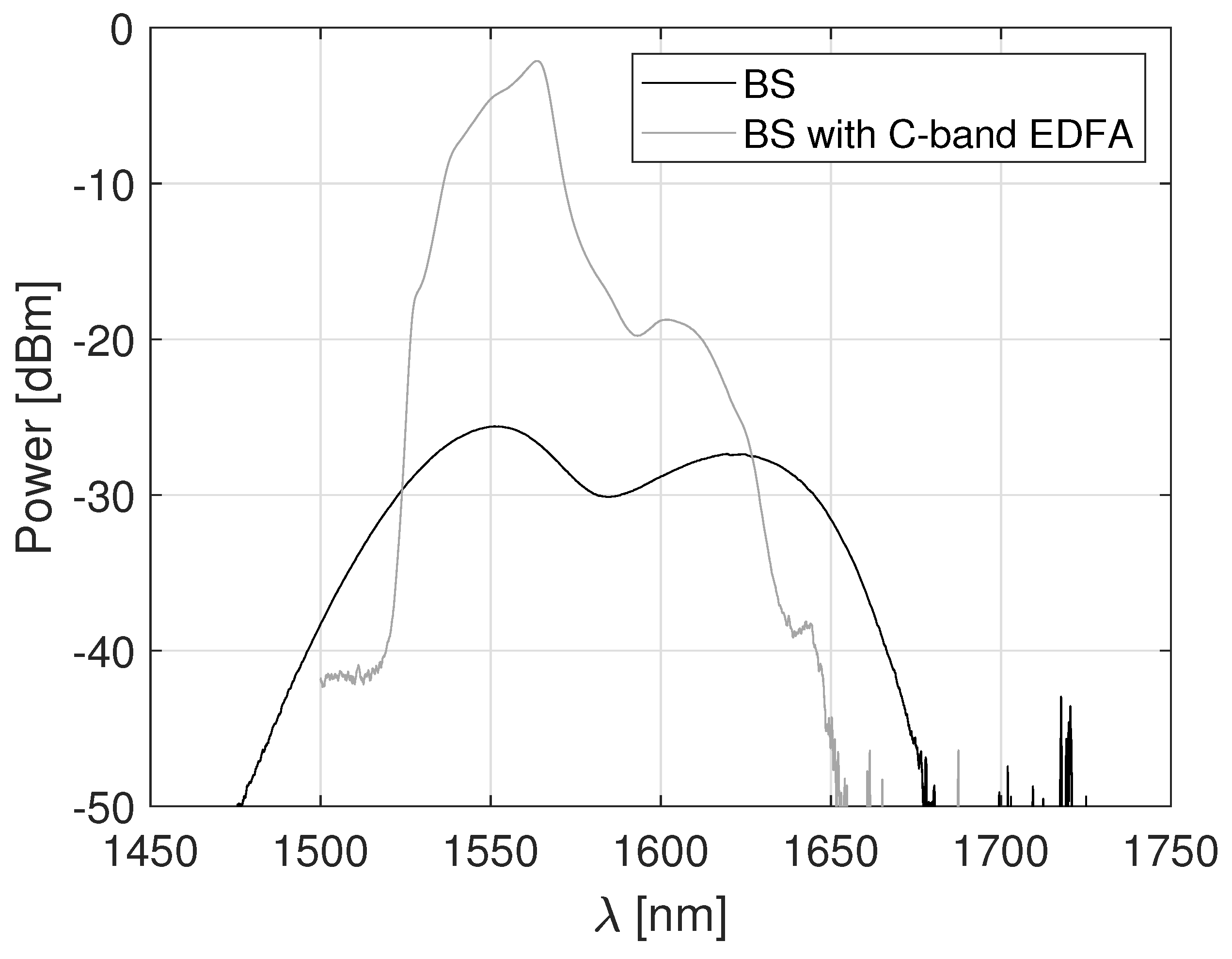
Finally, the in-band XT within the C-band is evaluated. In this scenario, the data generation module of
Figure 5 is based on a C-band broadband source (BS) and an EDFA. The power profile before and after amplification is shown in
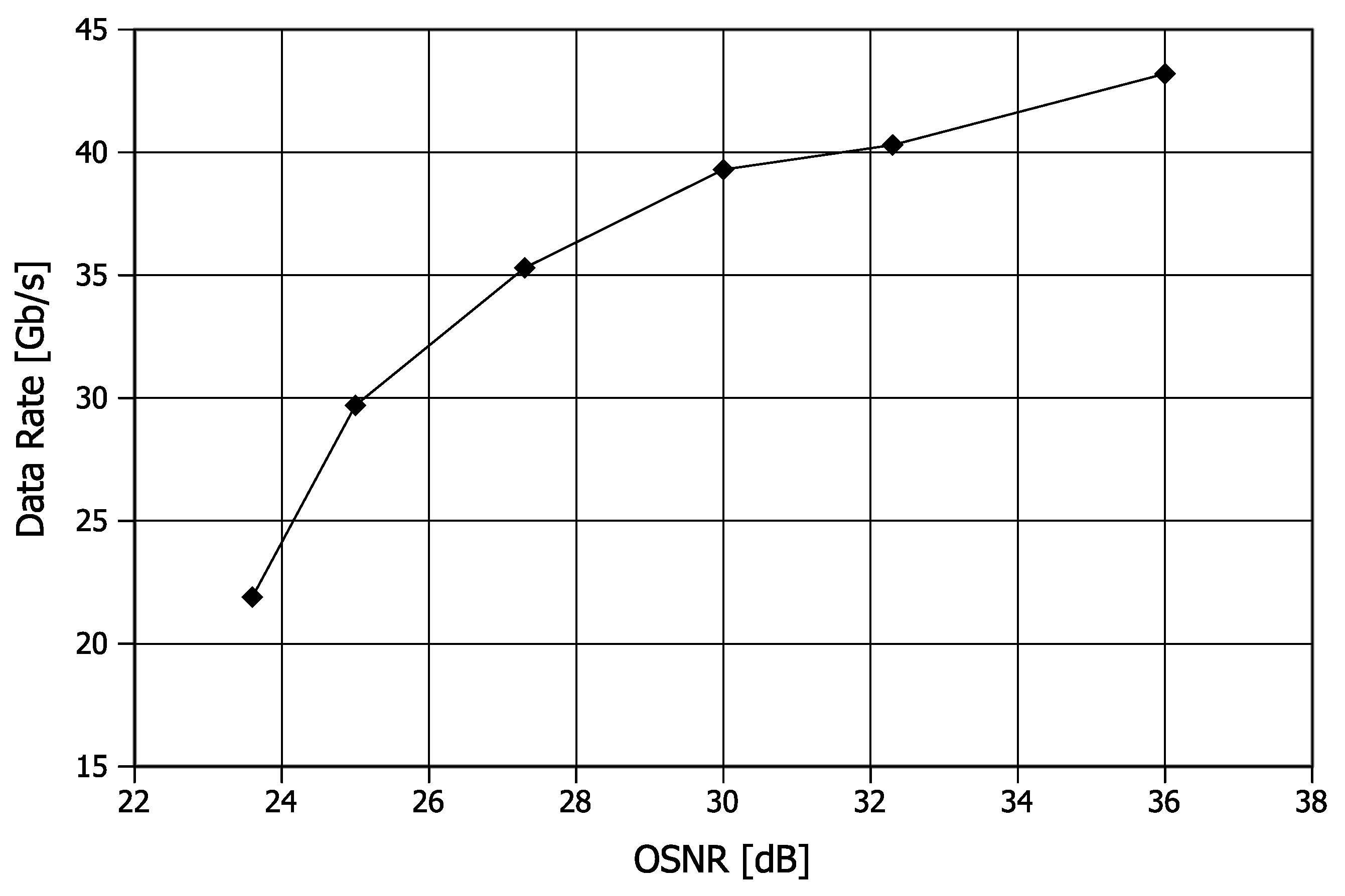
Figure 11. We have varied the output power of the EDFA in order to vary the impact of the in-band XT. As a result, the achieved data rate versus OSNR is depicted in
Figure 12. From the figure, it can be seen that a maximum data rate of 44 Gb/s (point A) is achieved without XT at 35 dB OSNR and the target BER. The data rate of the C-band contribution decreases with the increasing of the in-band XT signal power down to 22 Gb/s (point B) at
dB OSNR. So, despite the MCF is designed to reduce the XT levels, when the signal power of the neighbouring/adjacent cores is very high, it can lead to XT issues and interfere with the signal of interest by inducing optical interference and unwanted coupling between the cores, degrading the overall performance and limiting the capacity, as seen in the results of
Figure 12. This highlights the importance of managing signal power levels of the different cores, to minimize the in-band XT for reliable communication.
6.3. Complexity/Cost Analysis of the Proposed MB(oSDM) S-BVT
In this paper, we have proposed to implement a MB(oSDM) S-BVT based on IM and DD to target cost efficiency when comparing with alternative implementations based on coherent detection taking advantage of cost-effective optoelectronic subsystems and simplified DSP. According to [
46], the adoption of DD technology, at the receiver side, instead of coherent detection reduces the S-BVT cost of about 25–35%. Additionally, a comparison of the cost of 2 × 50 Gb/s S-BVT based on DD and coherent solution at 100 Gb/s (4 × 25 Gb/s) is provided in [
46], showing intrinsic cost savings when adopting a DD implementation. However, the proposed MB(oSDM) S-BVT, of
Figure 1, has additional elements to consider in terms of cost analysis due to the exploitation of MB technology. Hence, here we provide a cost analysis of the proposed transceiver solution based on external modulation and simple DD photodetection. For the cost analysis, we consider that the optical aggregator/distributor element of the MB(oSDM) S-BVT comprises WSSes shared among all the BVTs working in a specific band and BPFs to implement MB technology.
Table 2, shows the number of components required to implement the proposed transceiver based on DD considering 3 transmission slices at different bands (S+C+L) at 50 Gb/s.
Thus, the unitary cost of a building block in the C-band of the proposed MB(oSDM) S-BVT based on DD is:
M and
N are the number of DAC/ADC and WSS ports, respectively, and
B the number of BPF outputs, corresponding to the number of bands. We have considered that the WSS working in a particular band at the transmitter and receiver are the same. The unitary cost for the L-band and S-band building blocks will depend on the same individual parts/elements which include the LS, MZM, driver, DAC, WSS, PD, ADC, and BPF. However, the cost of specific components such as LS and WSS working in S- and L-bands are higher than the ones in the C-band due to the availability and maturity of the technology in the specified bands. As an example, the cost of the S-band LS (EML) used in the experiments is almost 5 times higher than the cost of the C-band LS (TLS), which both are from the same provider/manufacturer. Additionally considering similar WSS modules from the same provider, the cost of the WSS in the L-band can be increased by a factor of
when comparing with the C-band one. Hence, we consider
, and
scaling factors
to define the relationship in terms of cost of the LS and WSS in the S- and L-band with the corresponding C-band elements, respectively. Taking into account all this, the total cost for the 150 Gb/s MB(oSDM) S-BVT (3 × 50 Gb/s) can be defined as:
According to Equations (
5) and (
6) and reference [
46], the cost of the MB(oSDM) S-BVT, when only enabling the C-band, will slightly increase compared to a S-BVT that can not enable MB technology. Specifically, this increase is mapped with the cost term of using BPFs (
), which are static filters using very cheap technology of the order of few hundred euros. The seemingly extra cost of deploying the MB(oSDM) S-BVT is justified by the substantial improvements it brings to the optical network’s capabilities. In particular, the increased available spectral resources and the dynamic capacity scalability by enabling multiple slices in different bands beyond C-band. It is also worth to point out that due to the higher-cost of technology beyond C-band it will exist a trade-off between performance/capacity and cost. This trade-off introduces a strategic decision point that network planners and operators will carefully evaluate from a holistic network perspective before taking specific actions.


 ,
, 


