Article

A Multi-Service Adaptive Semi-Persistent LTE Uplink Scheduler for Low Power M2M Devices

1
School of Engineering, University of Newcastle, Callaghan, NSW 2308, Australia
2
School of Mechanical and Electrical Engineering, University of Southern Queensland, Springfield, QLD 4300, Australia
*
Author to whom correspondence should be addressed.
Future Internet 2022, 14(4), 107; https://doi.org/10.3390/fi14040107
Submission received: 2 January 2022 / Revised: 23 March 2022 / Accepted: 25 March 2022 / Published: 27 March 2022
(This article belongs to the Special Issue AI, Machine Learning and Data Analytics for Wireless Communications)

Abstract

:
The prominence of Machine-to-Machine (M2M) communications in the future wide area communication networks place various challenges to the cellular technologies such as the Long Term Evolution (LTE) standard, owing to the large number of M2M devices generating small bursts of infrequent data packets with a wide range of delay requirements. The channel structure and Quality of Service (QoS) framework of LTE networks fail to support M2M traffic with multiple burst sizes and QoS requirements while a bottleneck often arises from the limited control resources to communicate future uplink resource allocations to the M2M devices. Moreover, many of the M2M devices are battery-powered and require a low-power consuming wide area technology for wide-spread deployments. To alleviate these issues, in this article we propose an adaptive semi-persistent scheduling (SPS) scheme for the LTE uplink which caters for multi-service M2M traffic classes with variable burst sizes and delay tolerances. Instead of adhering to the rigid LTE QoS framework, the proposed algorithm supports variation of uplink allocation sizes based on queued data length yet does not require control signaling to inform those allocations to the respective devices. Both the eNodeB and the M2M devices can determine the precise uplink resource allocation related parameters based on their mutual knowledge, thus omitting the burden of regular control signaling exchanges. Based on a control parameter, the algorithm can offer different capacities and levels of QoS satisfaction to different traffic classes. We also introduce a pre-emptive feature by which the algorithm can prioritize new traffic with low delay tolerance over ongoing delay-tolerant traffic. We also build a model for incorporating the Discontinuous Reception (DRX) mechanism in synchronization with the adaptive SPS transmissions so that the UE power consumption can be significantly lowered, thereby extending their battery lives. The simulation and performance analysis of the proposed scheme shows significant improvement over the traditional LTE scheduler in terms of QoS satisfaction, channel utilization and low power requirements of multi-service M2M traffic.

1. Introduction

Machine-to-Machine (M2M)/Machine Type Communications (MTC) is the key enabler of the imminent connected world of Internet of Things (IoT), which would encompass a massive number of objects with variable capabilities and connectivity requirements. The ubiquitous presence and robust infrastructure of commercially deployed LTE networks offer an attractive solution to the M2M challenge, both from the technical and commercial perspective. Yet there are unforeseen complications which require novel solutions since there is a huge increase in the number of end users and their usage profile exhibits a whole different paradigm [1,2].
The 3GPP has launched specifications defining the service requirements and corresponding system improvements for MTC to design significant device and network modifications in the latest releases of LTE [3,4]. The key challenges for massive M2M deployment include small and intermittent data bursts with variable application-specific delay and reliability requirements generated by massive number of autonomous devices. Unlike the current human-centric traffic, they incur a higher traffic volume on the uplink and the limited Quality of Service (QoS) framework supported by LTE evidently fails to address their requirements. The initial near simultaneous access attempts taken by a huge number of devices have led most of the research initiatives to focus on the random access procedure, and propose several prioritization/multiple access methods [5,6,7].
Nevertheless, a major system bottleneck for realizing M2M-enabled LTE networks has been paid insufficient attention which is the uplink grant conveying process in LTE and its dependency on downlink control channel resources. Once the devices are connected after successful random access procedure, each device initiated/terminated transmission has to be scheduled in the time-frequency resource grid by the LTE packet scheduler and these scheduling grants must be signaled beforehand via the Physical Downlink Control Channel (PDCCH). However, the PDCCH resources are limited as compared to the data channel resources. Therefore, in case of M2M communications involving massive number of uplink requests, the scarcity of PDCCH resources are very likely to cause under-utilization of the system capacity [8,9]. Moreover, during this whole process, the M2M devices need to actively monitor the PDCCH for possible grants which drains their battery. Given the actual amount of M2M user data transmitted in the uplink is often very small (in order of few Kbytes), the time and resources consumed in the dynamic scheduling process of the LTE standard is extravagant and imprudent. For an efficient and long-term solution of the M2M communications, the signaling overhead of the scheduling process as well as power consumption of the devices need to be reduced [10].
In the 3GPP standards, Semi-Persistent Scheduling (SPS) [11] was proposed to resolve control channel congestion for voice traffic with a deterministic flow and predictable burst size, but it fails to meet the requirements of diverse M2M applications with stochastic flow and different burst sizes. The standards [12] also propose the Discontinuous Reception (DRX) mechanism as an effective power saving mechanism that allows the LTE User Equipment (UE) to turn their transceivers off when there is no incoming traffic. The DRX mechanism seems very attractive for low power M2M communications because of a small data per terminal in irregular intervals. The sleep cycles of many delay tolerant M2M applications can be scheduled so that they are allowed to transmit only in network-permitted time intervals, thus alleviating the network load in peak times and also saving device power. However, again, many M2M applications have a random traffic arrival pattern and variable burst sizes depending on specific events and triggers, and variable delay tolerances depending on the event type. The random arrival of uplink packets non-synchronized with the DRX sleep cycle may result in either unacceptably long packet delays or the UE seldom entering sleep state. These problems need to be addressed to achieve the utmost benefits of the SPS and DRX mechanisms for low control-overhead and low power requirements of M2M communications.
In view of these unique challenges, in this paper, we propose a multi-service adaptive semi-persistent scheduler which allocates the radio resources to the M2M devices/gateways in a semi-persistent way to reduce downlink control signaling yet adaptive to the actual M2M data burst sizes and also sensitive to the different QoS (delay budget) requirements of various M2M services. Our proposed scheduler can also alter the SPS allocations in real-time to make room for high priority M2M transmissions with small and strict delay requirements by pre-empting the already allocated but less delay-sensitive traffic classes. Afterwards, to support low-power devices, we design a mechanism to deploy the DRX mechanism in harmony with the adaptive SPS transmission intervals to maximize device sleep cycles without compromising the class-specific delay requirements. The proposed algorithm is simulated using the Riverbed modeler and the performance is analyzed and compared with the dynamic scheduler in terms of QoS, power consumption and channel utilization.
The idea of our adaptive SPS algorithm was proposed in [13,14,15] and we also derived a statistical model for the device queue size and packet delay for static and adaptive persistent allocations for any arrival process in [16]. In this paper, we present an extended work by introducing a system model for multi-service adaptive SPS algorithm with priority-based pre-emptive feature to distinguish between traffic classes and maximize overall QoS satisfaction and also enhance the algorithm by combining with DRX for supporting power-constrained M2M devices. The novel contributions of this paper are listed below:
  • Design of a system model which offers different capacities to multi-service M2M traffic classes with variable burst sizes and packet delay budgets.
  • Introduction of a control mechanism to vary the semi-persistent period according to the required QoS for different adaptive allocation policies.
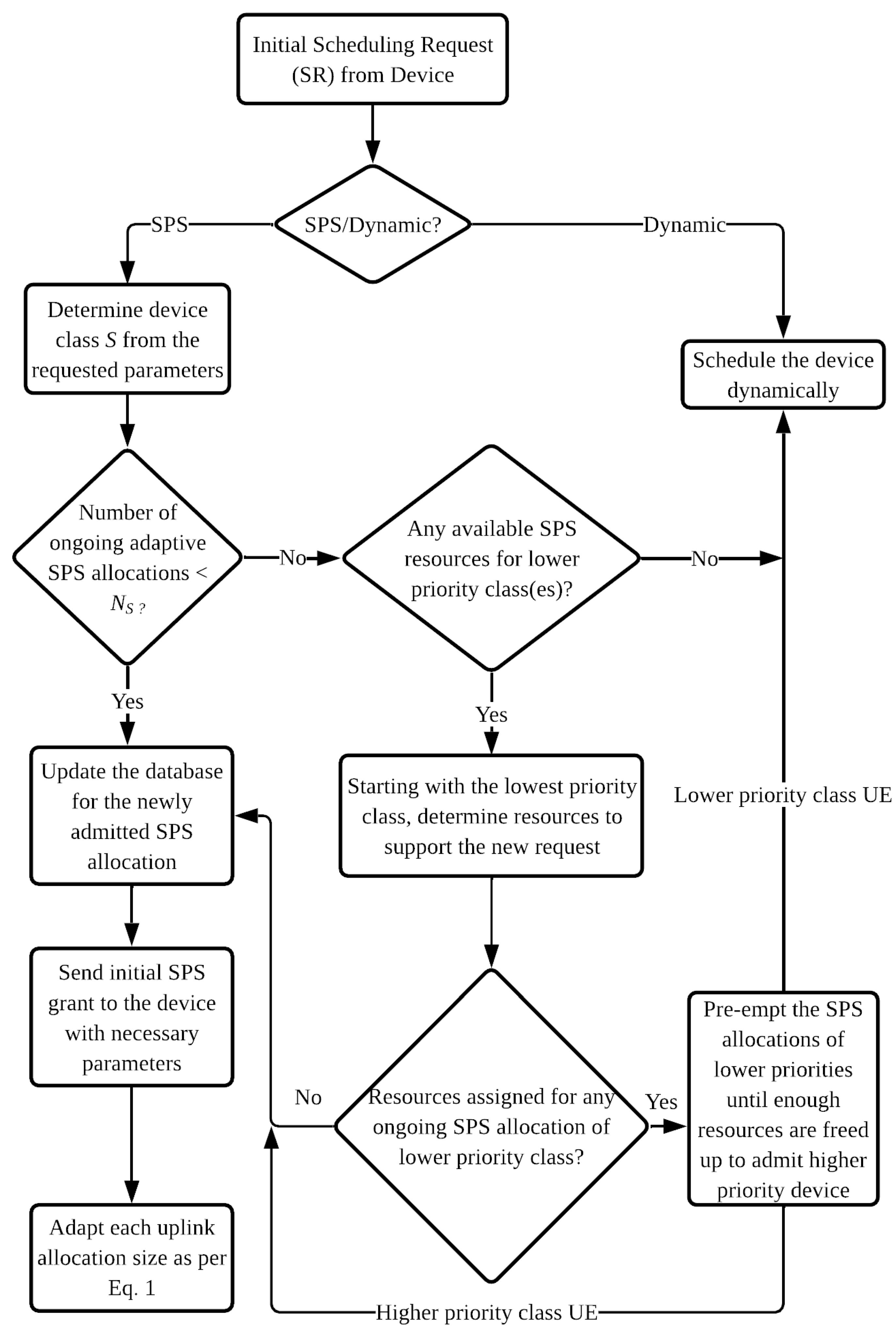
  • Pre-emption of low priority traffic (can be served dynamically in a best-effort way) upon arrival of higher priority traffic with more stringent delay budgets.
  • Reduction in power consumption of M2M UEs with DRX-enabled adaptive SPS mechanism without compromising their QoS requirements.
The rest of the paper is organized as follows: Section 2 provides the background of this work, Section 3 describes the proposed multi-service adaptive SPS algorithm, Section 4 explains the implementation of DRX within the proposed framework to achieve power saving, Section 5 presents the simulation parameters. In Section 6, we discuss the results and finally, Section 7 draws the conclusion.

2. Background

2.1. Related Enhancements for M2M Communications

The 3GPP has undertaken steps for supporting low-cost, low power-consuming M2M UEs by introducing new physical and MAC layer features in the latest LTE releases yet using the existing network infrastructure as much as possible. To reduce signaling complexity, Uplink Configured Grant (CG) transmission was proposed in 3GPP Release 15 instead of Dynamic Grant (DG) [17,18].
To reduce signaling load on the radio network, group-based scheduling approaches have been investigated. In [19], the authors proposed a cluster-based massive access management scheme by dividing the M2M devices in a number of clusters and assigning them periodic Access Grant Time Intervals (AGTI) according to their packet arrival rate, in a fixed or opportunistic manner depending on their QoS requirements. However, only constant inter-arrival gap and fixed packet size are considered. In [20], an extension is made to the AGTI algorithm [19] for maintaining jitter at the desired level for the already allocated clusters by barring any new M2M device to join the cluster if certain conditions are not met. Nevertheless, the limitations of the AGTI algorithm i.e., fixed size deterministic traffic flows remain which makes it unsuitable for event-based M2M traffic.
In [21], the authors developed QoS and queue-length aware uplink scheduling algorithms targeting M2M service clusters. To improve the limitations of the AGTI framework, in [22], they provided an analytical model to combine the statistical delay violation probability with an allocated grant interval. They used Poisson arrival pattern and the periodic grants also reduced control overhead significantly, but they do not examine the effect of variable sized data burst and the individual grants are still fixed in size (number of PRBs) which can be inefficient.
In the review article [23], the authors have classified and compared various scheduling techniques for M2M communications in LTE and discussed the potential of semi-persistent scheduling for massive access, which is still not studied in depth.
Several works have explored the potential of DRX for UE power saving [24,25,26,27,28]. In [27], a DRX and QoS-aware scheduling algorithm was proposed which aimed to minimize the ON-duration of the UEs, but it considered only conventional QoS classes defined in the LTE standard. The algorithm in [28], proposed to dynamically adjust the DRX parameters by considering channel conditions and QoS. However, the application of DRX for M2M traffic has not been evaluated anywhere else and the strategy of coupling it with adaptive SPS is a unique concept which we examine in this paper.

2.2. Dynamic Scheduling in LTE

The LTE radio resources are distributed in a time-frequency grid. For every Transmission Time Interval (TTI), the available PRBs for data channels are allocated to the UEs selected by the eNoedB packet scheduler and the downlink/uplink scheduling decisions are communicated to the respective UEs via the PDCCH [29]. For downlink transmissions, the eNodeB sends the grant information while the corresponding UE is monitoring the PDCCH followed by the actual data received by the UE in the designated downlink resources. In case of UE generated traffic, the device needs to send a Scheduling Request (SR) [29] first to the eNodeB in the uplink control channel, and then continuously monitor the PDCCH for possible uplink allocations. Upon reception of the desired grant, the UE makes the transmission in the designated uplink resources attached with a Buffer Status Report (BSR) [30]. If the BSR indicates the requirement of further resource allocation, the UE is again entered in the scheduling queue of the eNodeB and needs to keep monitoring the PDCCH for subsequent grants. The scheduling process is called dynamic because the allocated bandwidth can vary from one allocation to another as well as the timing and Modulation and Coding (MCS) [29] schemes can be adapted based on UE channel conditions and QoS requirements. However, this flexibility comes at a cost of PDCCH signaling overhead and increased power consumption of the UEs for monitoring and processing of control information.

2.3. Adaptive Semi-Persistent Scheduling (SPS)

The adaptive SPS is a series of PUSCH resources semi-persistently allocated to an LTE UE, where the allocations have a fixed period T S P S in the time domain but the allocation size is variable in the frequency domain. The adaptation of the allocations is done in terms of the number of PRBs utilizing the BSR reported by the UE within its transmitted uplink data unit to vary the PRBs allocated for the next semi-persistent transmission. The BSR is piggybacked with the uplink data unit, hence does not require any explicit control channel resources. The uplink scheduler considers this BSR information for determining the future uplink resources according to a customized function and the UE can also determine the exact amount and time-frequency co-ordinates for the allocation using this mutual knowledge.
Instead of signaling ahead of each uplink transmission separately, the following parameters are signaled via the PDCCH before the UE can initiate their adaptive SPS uplink transmissions: the adaptive SPS period, T S P S , uplink subframe number, i, initial frame offset, j, MCS index, I M C S , starting index of the contiguously allocated uplink PRBs, k, the maximum number of allocated uplink PRBs N P , m a x in a subframe and the adaptation function f u n c ( B ) which is used to calculate the adaptively allocated number of PRBs for each new transmission based on the latest BSR information B.
The supported adaptive SPS periods are always integer multiples of the LTE frame duration. This constraint is required to avoid changes in the allocated uplink subframe number for the subsequent adaptive SPS transmissions from the same device. Initial frame offset indicates the number of frames the device has to wait until they can begin the adaptive SPS transmissions. More than one device can use the same uplink resources for adaptive SPS transmission if they have the same value of T S P S yet different initial frame offsets (j) assigned to them which means they are multiplexed in time.

3. Multi-Service Adaptive Semi-Persistent Scheduling Algorithm

3.1. Adaptive Frequency Domain Scheduling

In our system model, we consider an LTE system which has a frame duration of 10 milliseconds (ms) and consists of 10 subframes. For a Frequency Division Duplex (FDD) system, there are 10 uplink subframes in a frame whereas in a Time Division Duplex (TDD) system, there is a certain downlink/uplink subframe ratio depending on the TDD configuration. Any uplink traffic class S supported by the adaptive SPS algorithm will have its subscribers assigned to one or more uplink subframes in the LTE frame.
Each traffic class is designated with an SPS allocation period T S P S , S which means the allocations are periodic in the time domain with a constant inter-allocation gap. Each subscriber of that class is further allowed to consume variable number of PRBs within a pre-negotiated range in the frequency domain. The variation of the allocated PRBs to a subscriber device is dependent on the latest buffer report of the device which is known to both the device and the eNodeB, and hence does not require to be signalled explicitly. Therefore, for a particular traffic class S, the instantaneous number of uplink PRBs assigned to the adaptive allocation in the frequency domain, N P , A S can vary according to Equation (1).
N P , A S = min N P , f u n c B , N P , m a x ( S ) , f o r N P , f u n c B > 0 1 , o t h e r w i s e
where N P , f u n c ( B ) = N P , B l a t e s t , for buffer-based adaptive allocations, which means the adaptation function utilized here is the number of uplink PRBs required to transmit the data volume indicated by the latest BSR report of the subscriber device. Note that such an adaptation function uses a reactive approach, so as to grant a conservative amount of resource to only accommodate the data which was already present in the UE buffer at the time of the previous adaptive SPS transmission, which is prudent from resource efficiency perspective, but comes at an expense of increased packet delay. The PRB ceiling N P , m a x ( S ) is set with the initial grant depending on a number of factors such as the expected data volume of the traffic class S at each SPS interval, and availability of contiguous uplink PRBs which may depend on the instantaneous occupancy of the system by already saved SPS allocations.
We assume each uplink subframe in the LTE frame supports only one adaptive SPS traffic class, S. The class S supports maximum n S subscribers, each having the same adaptive SPS period T S P S , S and the same adaptation function for the instantaneous number of adaptively calculated PRBs N P , A S . If the maximum possible number of adaptively allocated uplink PRBs to each of the n S subscribers is given by N P , m a x ( S ) , then the total maximum number of adaptively allocated PRBs for all subscribers of the class S in any given uplink subframe, R S , m a x is expressed by Equation (2).
R S , m a x = n S N P , m a x ( S )
If R is the number of total uplink PRBs for that particular subframe, then the relation between R S , m a x and R must be governed by Equation (3).
R S , m a x R
For demonstration purpose, we consider an LTE TDD system with configuration 6 that has 5 uplink subframes per frame. Figure 1 demonstrates how 5 adaptive SPS traffic classes A, B, C, D and E are implemented for this configuration where each class is assigned to one uplink subframe. For 3 MHz bandwidth and 2 PRBs reserved for uplink control information, R = 13 PRBs are available for scheduling uplink data. In this example, traffic class A supports n S = 3 subscribers in one subframe and they occupy the range of PRBs r A 1 , r A 2 , r A 3 respectively in the example scheduling instance. The possible maximum number of adaptively allocated PRBs for class A in the example is, N P , m a x ( A ) = 3 . The Other traffic classes are shown similarly.

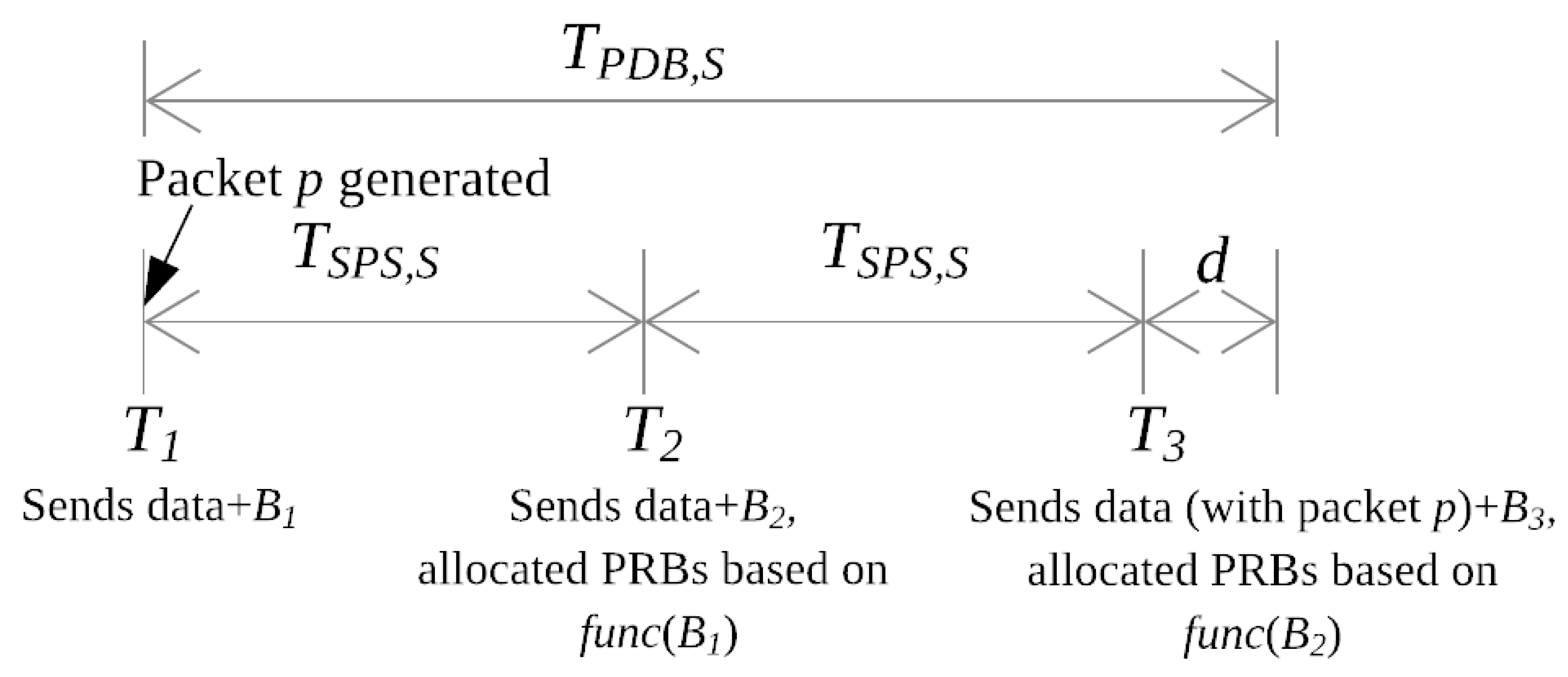
3.2. Control Mechanism for the Adaptive SPS Period

The SPS period assigned to each traffic class has a significant impact on the overall service capacity of the class and also on their QoS performance. From the principle of the adaptive SPS, for any traffic class S, the assigned SPS period T S P S , S is selected to be an integer multiple of the LTE frame duration T F so that the subframe number designated to the traffic class is not changed and different subscribers to the traffic class can be multiplexed in different frames. The condition can be expressed as Equation (4).
T S P S , S = m S T F
where
  • m S is an integer number.
  • T F is the LTE frame duration, fixed at 10 ms [29].
On the other hand, Equation (5) introduces a control mechanism for variation of the adaptive SPS period for QoS guarantee of the traffic class S.
T S P S , S = f S T P D B , S
where T P D B , S is the PDB of traffic class S and f S is a fractional value i.e., 0 < f S < 1 , so that T S P S , S does not exceed the value of their class-specific T P D B , S . Here, f S is a control parameter that can be varied to control the statistical delay budget violation probability of the respective traffic class S.
In Figure 2, the hypothetical worst case packet delay experienced for traffic class S is demonstrated, with the assumption that at each adaptive SPS transmission, the system would have enough PRB capacity to accommodate the data reported by the latest BSR of the requesting device i.e., N P , m a x ( S ) is sufficiently large.
As shown in Figure 2, the device sends uplink data along with BSR B 1 to the eNodeB at time T 1 . The packet p is generated and enters the device buffer immediately at T 1 , so its volume could not be included in B 1 . Consequently, the device and the eNodeB both calculate the allocated number of PRBs for the next adaptive SPS transmission ( N P , A S ) T 2 occurring at time T 2 as a function of B 1 (as per Equation (1)). Therefore, packet p would not be served with the allocation ( N P , A S ) T 2 i.e., PRBs allocated at time T 2 . However, the volume of packet p would be indicated in the next BSR B 2 , sent at time T 2 . The allocated resources ( N P , A S ) T 3 at time T 3 is based on B 2 and can accommodate packet p. Since the LTE subframe duration or TTI is equal to 1 ms which we denote here by d, the transmission of packet p is completed at time ( T 3 + d ) . For class S, the worst case hypothetical packet delay T m a x , S can be expressed by Equation (6).
T m a x , S = 2 T S P S , S + d
Setting the value of T m a x , S as T P D B , S (ms) and substituting d by its actual value, we obtain the necessary condition for T S P S . S to ensure all the packets meet their delay budget as shown in Equation (7) (where all values are expressed in milliseconds).
T S P S , S T P D B , S 1 2
Therefore, the upper limit of the adaptive SPS period, T S P S , S to support a given QoS requirement of any delay-bound M2M traffic class is given by Equation (8), if sufficient uplink resources are avaliable at each transmission opportunity.
T S P S , S < T P D B , S 2
By combining Equations (5) and (8), we derive the condition for the control parameter f S for any traffic class S to fulfill the class-specific delay budget requirements.
f S < 0.5
It should be noted that for the buffer-based reactive adaptation function, the value of the control parameter should be in the range 0 < f S < 0.5 . On the other hand, higher values in the range 0.5 f S < 1 support longer SPS periods but the delay budget violation probability is also higher. In order to benefit from the longer SPS periods as well as to avoid excessive packet delay, the adaptation function in Equation (1) should be modified to allocate higher number of PRBs (greater than the PRBs required to serve the latest reported buffer) to the device in a predictive manner to closely match the instanteneous buffered data volume at the device at the next SPS transmission opportunity.

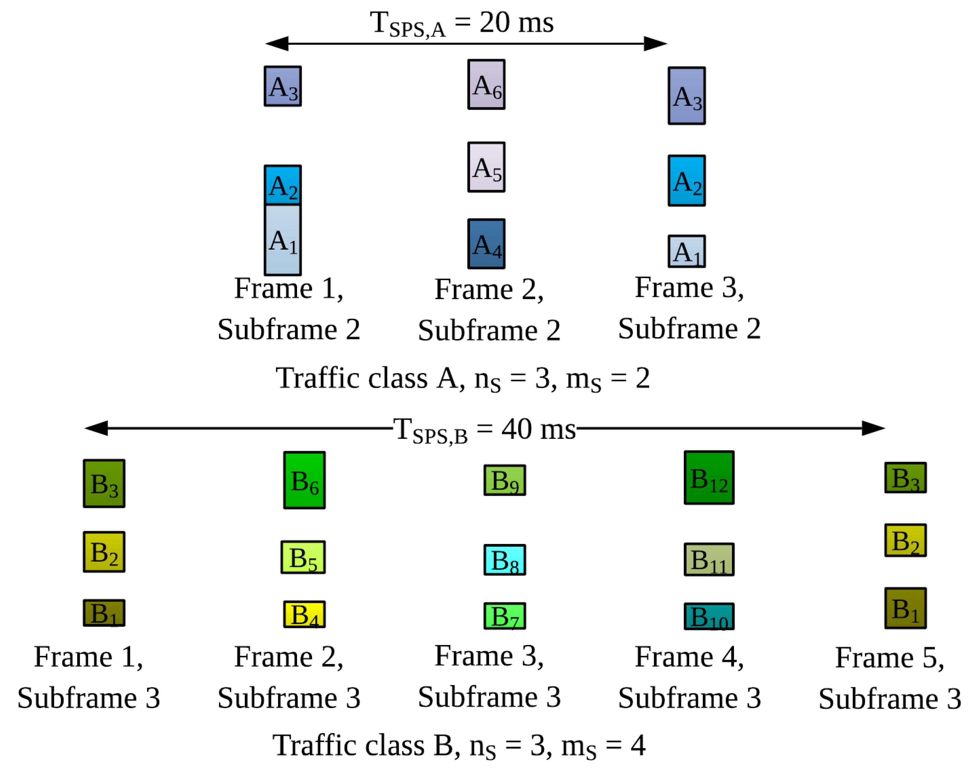
3.3. Intra-Class Time and Frequency Domain Multiplexing

For any traffic class S, if m S = T S P S , S T F > 1 , the adaptive allocation of PRBs to the n S subscribers (occurring in the same uplink subframe) are repeated every m S number of LTE frames. So we can multiplex m S instances of an uplink subframe (each serving n S subscribers) in m S different frames. Therefore, for intra-class scheduling, we can deploy frequency and time domain multiplexing simultaneously. Hence, the service capacity of the any traffic class S (for one particular uplink subframe) is given by the total number of supported adaptive SPS subscribers N S as shown in Equation (10).
N S = n S m S
In the example demonstrated in Figure 3, for T S P S , A = 20 ms , n S = 3 and m S = 2 , the traffic class A can support 6 subscribers in subframe 2. Similarly, for T S P S , B = 40 ms , n S = 3 and m S = 4 , the traffic class B can support 12 subscribers in subframe 3.
Now, if traffic class S is assigned to C number of uplink subframes in any LTE frame where 1 C 10 , the service capacity of class S in terms of supported adaptive SPS subscribers N S would be expressed by Equation (11).
N S = C N S = C n S m S
By replacing the expression for m S from Equation (4), Equation (11) can be re-written as Equation (12).
N S = C n S T S P S , S T F

3.4. Scheduling of H2H Traffic

So far, we described the allocation of PRBs to adaptive SPS users which is intended for M2M subscribers. However, this does not come at an expense of jeopardizing human users. As expressed in Equation (3), the maximum number of PRBs available for the adaptive SPS users in an uplink subframe, R S , m a x must not exceed the total uplink PRBs, R in a subframe. For fairness between M2M and H2H users, we reserve R H , r e s PRBs for H2H users per uplink subframe. Hence it follows:
R = R S , m a x + R H , r e s
The actual consumption of PRBs by the adaptive SPS users is often less than the allowed maximum (as the buffered data and is often very small or zero in case of M2M traffic).
Suppose, in an arbitrary uplink subframe, n S users of traffic class S instantaneously consume r ^ S 1 , r ^ S 2 , …, r ^ S n S PRBs respectively based on their buffered data. Then for the particular subframe, the actual number of total PRBs consumed by the adaptive SPS users, R ^ S is given by Equation (14) as follows:
R ^ S = i = 1 n S r ^ S i
Then, it follows that the rest of the PRBs unused from the maximum PRB limits of the adaptive SPS ranges i.e., ( R S , m a x R ^ S ) are also available for the H2H users and can be scheduled dynamically on an on-demand basis. So the total number of PRBs available for human users in one subframe would be given by R H as expressed by Equation (15).
R H = R H , r e s + R S , m a x R ^ S
By replacing R S , m a x from Equation (13), we get the expression for R H as given by Equation (16).
R H = R R ^ S
For any scheduling instance, the actual requirement of PRBs by the adaptive SPS users, R ^ S is determined first by the scheduler (based on the mutual knowledge of the eNodeB and the devices regarding the buffered data and using Equation (1)) and then the remaining R H PRBs available for the H2H users are scheduled dynamically according to the queued requests.

3.5. Multi-Service Adaptive SPS Algorithm

Figure 4 demonstrates the functionality of the multi-service adaptive SPS algorithm. Firstly, when an M2M UE (here we refer to both standalone M2M devices and M2M gateways as M2M UEs) sends an initial request, the algorithm checks whether the device requires an SPS or a dynamic allocation, which can be indicated by the request parameters and traffic patterns. If the M2M application sends one-off data without any specific pattern, then it is indicated in the device class which means the scheduling scheme would be dynamic. However, if the device has a regular pattern of intermittent traffic burst (which is non-deterministic such as Poisson arrival process), then the preferred scheduling scheme is adaptive SPS, subject to fulfillment of certain conditions.
If the UE requires an SPS allocation, the traffic class S is determined from the request parameters and the optimum value of SPS period T S P S , S is determined. The proposed algorithm aims to achieve maximum service capacity for each traffic class i.e., increasing the number of subscribers supported by adaptive SPS scheme thus saving control channel resources of the system. The higher the SPS period for a traffic class, the greater number of subscribers can be served by the SPS scheme for the same class (as per Equation (12)). However, the SPS period T S P S , S is proportional to the control parameter f S and the PDB T P D B , S of the class S . The PDB is constant for a class whereas the maximum value of f S is dependent on the adaptation function used in Equation (1). For the buffer-based adaptive SPS allocations, to meet the delay requirements, f S must be in the range 0 < f S < 0.5 . But the value of the SPS period T S P S , S must also satisfy the condition in Equation (4). Therefore, the optimum value of T S P S , S is determined by selecting the maximum value of f S in the supported range, while the SPS period is an integer multiple of the LTE frame duration i.e., 10 ms . For the buffer-based adaptive SPS allocations, the optimum value of T S P S , S is found for f S = 0.4, for all traffic classes. Since the theoretical supported range of f S for ensuring 100% packets are transmitted within their PDB values, is dependent on the adaptation function, not on the traffic patterns or the actual PDB values of the classes. Increasing the value of f S beyond that range would require changes to the adaptation function.
Afterwards, the scheduler checks with the uplink subframe(s) primarily designated for traffic class S whether there are enough resources available to admit the new user. This is done by comparing the number of ongoing adaptive SPS connections for class S to its service capacity N S . If enough resources are available then the new user is admitted for SPS allocation and the database is updated accordingly. Then the initial SPS grant is sent to the user device via PDCCH including the necessary parameters i.e., the designated uplink subframe number, starting frame number, the starting index, the range of PRBs allowed for the device and the required MCS index.
The device starts transmitting in its allocated resources and the buffered data volume is piggybacked with every uplink transmission (in form of BSR MAC control element). The BSR information sent with the tth uplink transmission is used to adapt the next i.e., ( t + 1 ) th allocation size by both the scheduler and the device with the calculation from Equation (1).
Whenever an SPS request is denied by the scheduler due to capacity constraint, the default scheduling scheme is dynamic. In case of the dynamic scheduler, the experienced packet delay is dependent upon many factors such as the instantaneous system load, data and control channel capacities etc. and in general, there is a higher probability of meeting the delay constraints for the traffic classes with higher delay budget. On the other hand, with the adaptive SPS algorithm, by issuing a semi-persistent adaptive allocation with an appropriate value of T S P S , S in accordance with the corresponding T P D B , S , the scheduler ensures a high statistical probability of meeting the delay constraints even for packets with small delay budget. The pre-emptive function is based on these phenomenon. Some traffic classes with small and strict delay budget may have priority over other classes with higher and less strict delay budget values. Due to this prioritization, if there is not enough capacity left to admit a new adaptive SPS request with higher priority, the packet scheduler searches if there are any SPS resources designated for traffic class(es) with lower priority. If sufficient resources to support the new request are found and they are already in use by any lower priority UE(s), these allocations are pre-empted and higher priority traffic is admitted and their new SPS grant is sent accordingly. If the pre-emption attempt is unsuccessful due to resource insufficiency, the current allocations are unchanged and the new request is scheduled dynamically. Another approach might be modification of the control parameter f S of the ongoing adaptive SPS allocations of lower priority traffic class(es), by assigning higher values of f S such as 0.5 f S < 1, so that they are allocated a range of longer SPS periods with a tolerable range of QoS degradation level.

4. Implementation of DRX Power Savings with Adaptive SPS

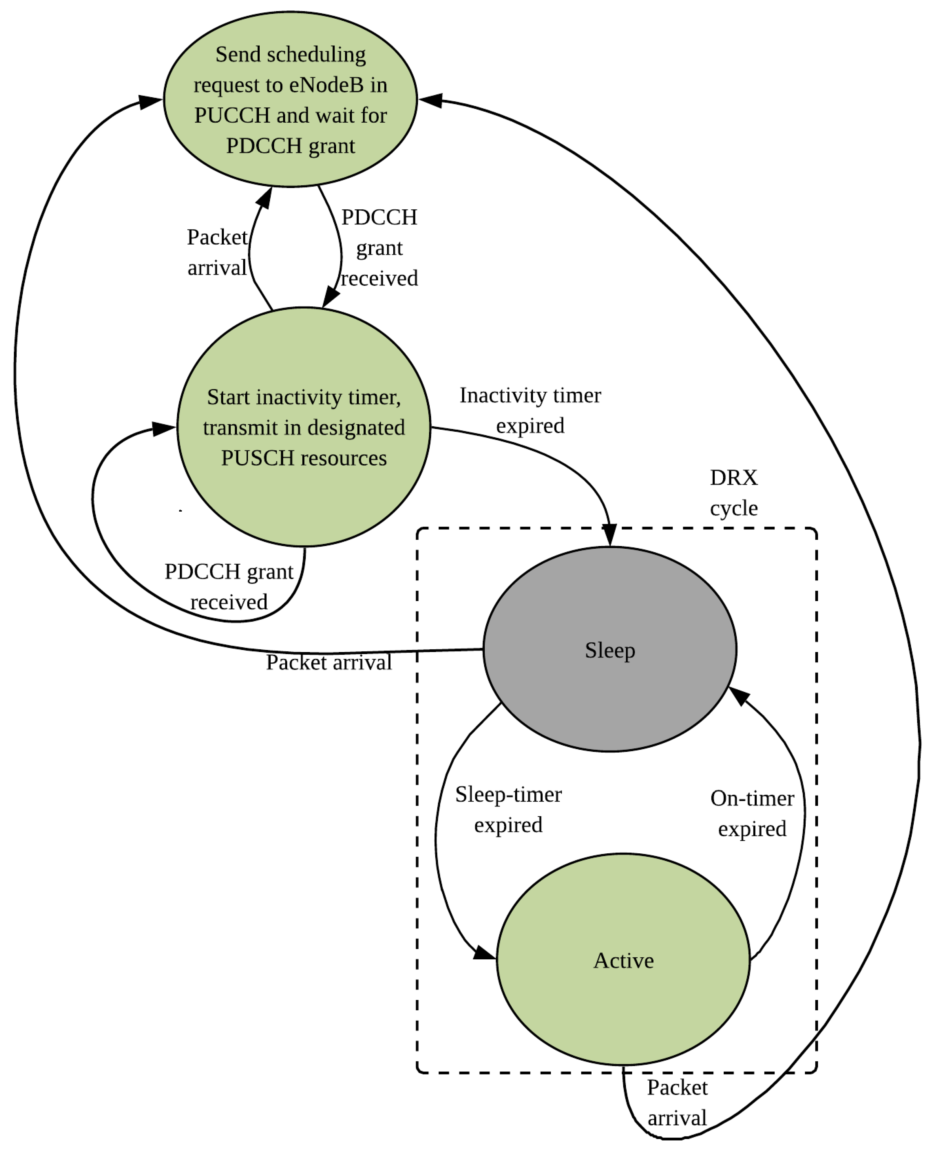
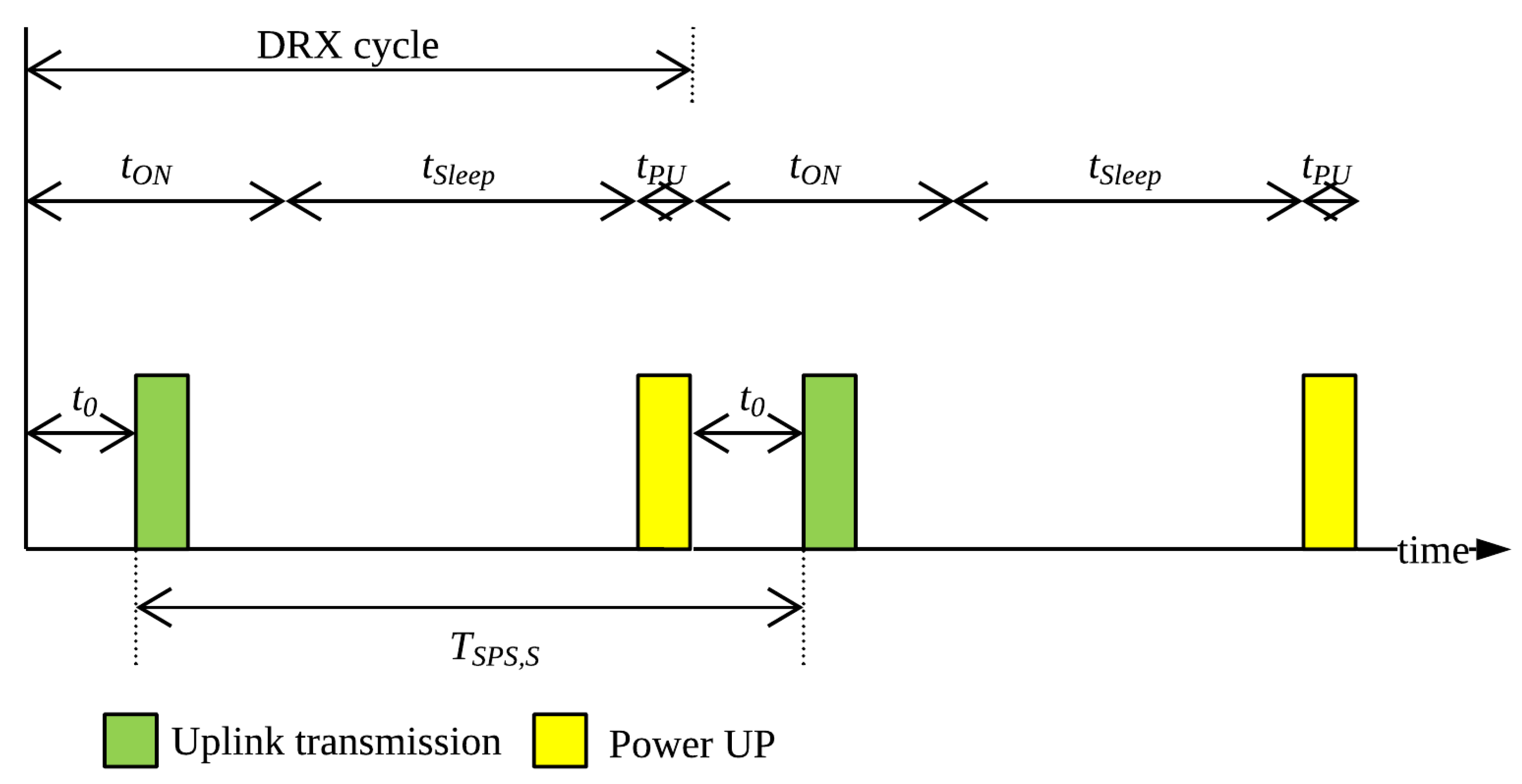
4.1. Standard DRX Mechanism

The 3GPP has standardized the DRX power-saving mechanism [12] to allow the UEs to enter a sleep mode when there is no data to be received. The UEs are configured with two parameters, i.e., the sleep period and the inactivity timer which determines how often and for how long the UE can remain in sleep by turning off its transceiver. A DRX cycle consists of a sleep period and an ON-period. In the sleep period, the UE is in power-saving state and does not monitor the PDCCH and any downlink packets arriving at the eNodeB destined for this UE needs to wait. At the end of the sleep period, the UE enters ON-period and monitors the PDCCH for possible scheduled transmissions. Two types of DRX cycles, short and long DRX are supported. The short DRX cycle has a short sleep period and it will be repeated until the expiry of a short DRX cycle timer, expressed in number of short DRX cycles, with no traffic. Upon expiry of the short DRX cycle timer, the long DRX cycle is started and is continued until traffic is indicated in the ON-period of the UE. If there is any PDCCH grant for this UE during the ON-period, the UE becomes active to process data and starts an inactivity timer. Whenever there is a new transmission or reception during the active state of the UE, the inactivity timer is reset and only upon expiry of it without any activity, the UE can start DRX cycle.
Figure 5 shows the DRX mechanism for uplink traffic in LTE. For initial packet arrival at the UE in its active state, a request in sent to the eNodeB using the Physical Uplink Control Channel (PUCCH) and the UE actively listens to the PDCCH for scheduling grant. Upon reception of the grant in PDCCH, the UE starts inactivity timer and transmits in the PRBs allocated to it in the Physical Uplink Shared Channel (PUSCH). If the BSR sent along with the data indicated the requirement of further allocations, new PDCCH grants are sent to the UE which makes it reset the inactivity timer. If the BSR was zero then the UE waits until the inactivity timer is expired. If there is new packet arrival before the timer expiry, again the SR process is executed. Otherwise, upon timer expiry, the UE can enter sleep state. If there is any packet arrival in sleep state, the UE wakes up immediately and sends SR. If the sleep timer is expired without any packet arrival then the UE enters ON-state. The UE actively monitors PDCCH in this state and in case of packet arrival starts the SR process. Only upon the expiry of ON-period without any event it can enter sleep state.
The DRX mechanism can save significant amount of UE power in the presence of occasional downlink traffic for the UE. However, for uplink-heavy M2M traffic with small and/or random inter-arrival gap, the UE has to wake up every time an uplink packet is generated. Moreover, for such arrival pattern, in most cases, there is data remaining in the UE buffer after each uplink transmission; thus keeping the UE awake and monitoring. All these factors prevent the UE to benefit from the DRX mechanism because the probability of the UE entering the sleep state and completing the sleep period becomes very low.

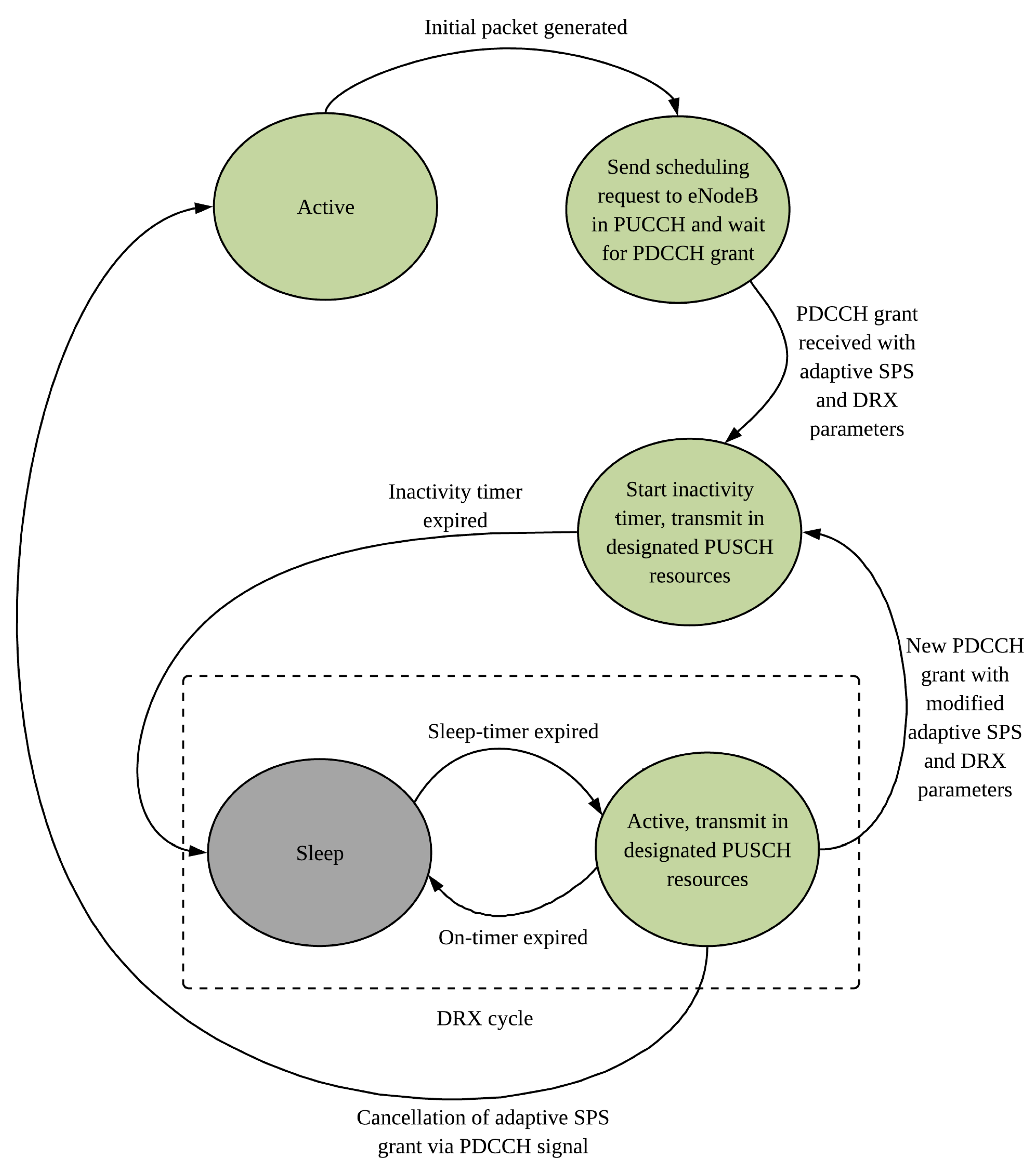
4.2. UE State Transitions with Adaptive SPS

In our proposed scheme, the UE only performs uplink transmissions periodically in the adaptive SPS allocations defined for it. Apart from the initial grant, the UE does not seek any PDCCH grants, therefore, it does not send any SR in case of new packet arrivals. So the process is much simplified. Figure 6 shows how maximum DRX power saving can be achieved by synchronizing the ON-period of the DRX cycle with the adaptive SPS transmission opportunities from the UE.
Initially, the UE is in the active state. When a new packet is generated by the UE, it sends an SR to the eNodeB and continuously monitors the PDCCH for uplink grants. Unlike the dynamic scheduling, the eNodeB responds with an adaptive SPS grant and DRX parameters. Accordingly, the UE starts an inactivity timer and transmits in the designated PUSCH resources. Upon the inactivity timer expiry (as no other PDCCH grants are due), the UE enters sleep state. During the sleep period, the UE does not wake up in case of new packet arrivals. When the sleep-timer is expired, the UE enters active state and makes the adaptive SPS transmission in its allocated PRBs and reports the amount of data left in the buffer (if any) to the eNodeB in the BSR. Upon the ON-timer expiry, the sleep period is started again. If the eNodeB requires to modify or cancel the adaptive SPS allocations, it sends a PDCCH signal during the ON-period of the UE and the UE acts accordingly. In this scheme, the randomness of packet arrivals and unpredictable PDCCH grants do not affect the entering/remaining in the sleep state of the UE. Thus the UE can save power by lengthening its sleep period, subject to matching with the delay tolerances of the buffered packets.

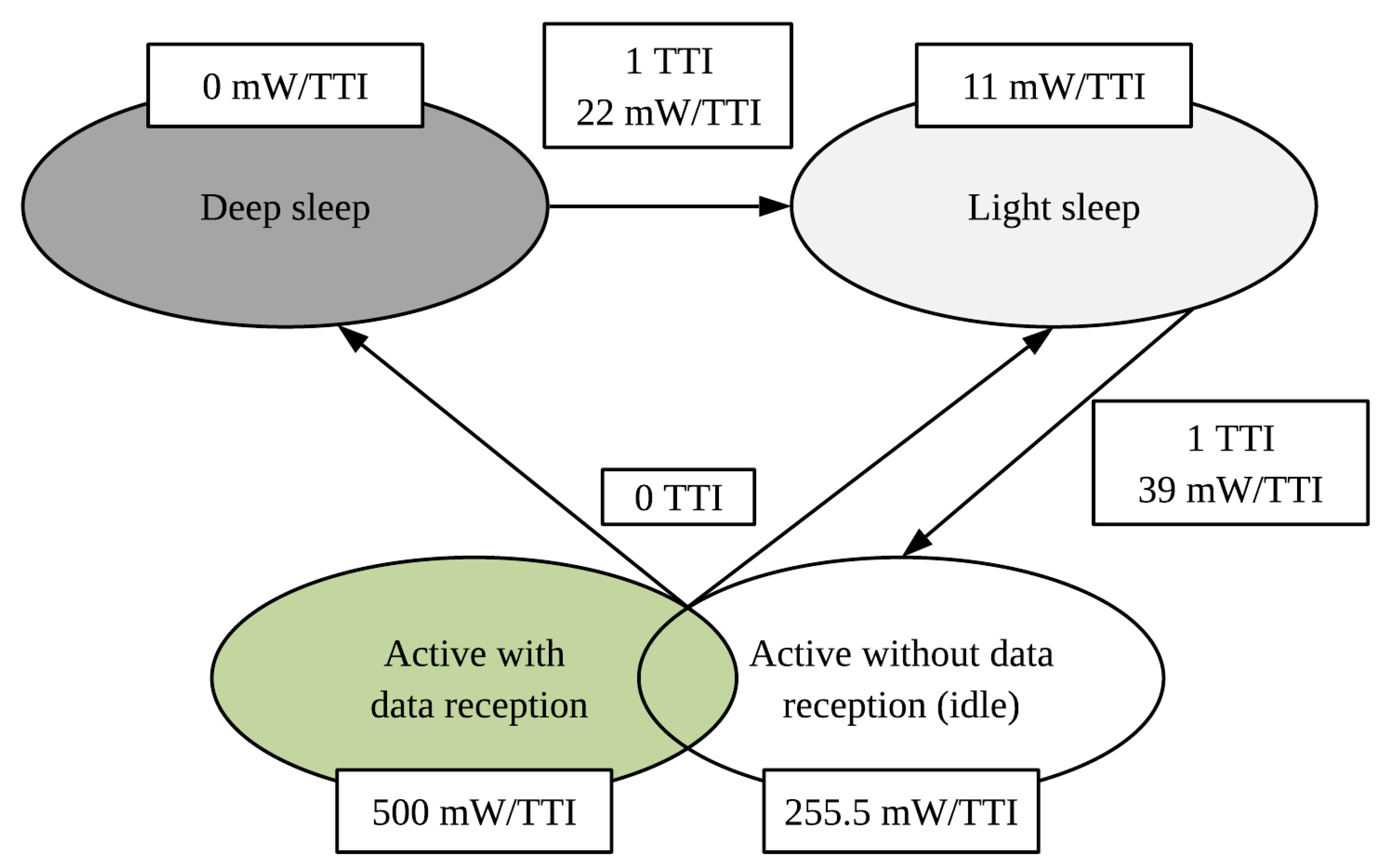
4.3. Sleep Period and Power Saving

Figure 7 shows the time frame of the adaptive SPS transmissions along with the DRX cycle for uplink traffic. During the ON-period, at time t 0 , the UE transmits data in the PUSCH. When time t O N is reached, the UE enters sleep state and remains in sleep for the duration of t S l e e p . At the end of the sleep state, the UE takes t P U time to power up from sleep to active. Then the ON-period is started again and uplink transmission is done at t 0 . The time between two successive transmission is the class-specific SPS period T S P S , S .
From Figure 7 it follows:
T S P S , S = t O N t 0 + t S l e e p + t P U + t 0
From (17) we can derive the relationship in (18).
t S l e e p = T S P S , S t O N t P U
So the sleep duration t S l e e p is dependent on the value of T S P S , S . To model the actual amount of power saving in different states of the DRX cycle, we implement the UE power consumption model presented in [31] which is also used in literature [28,32] for DRX-based analysis. The model is shown in Figure 8.

4.4. Power Saving through Predictive Allocation

For the reactive buffer-based allocations, the values of 0 < f S < 0.5 ensures satisfactory delay budget performance but shortens the supported SPS preiods which leads to shorter sleep cycles for the M2M devices. The values of 0.5 f S < 1 support longer SPS periods hence longer sleep cycles, but increases the waiting time for the packets in the buffer and the statistical probability of exceeding the delay budget values are much higher if the same buffer-based adaptation functions are used. To leverage the benefit of longer sleep cycles and compensate for the longer SPS periods, the scheduler must use predictive adaptation functions where the traffic arrival rates and BSR data would be utilized to predict the instantaneous amount of data in the device buffer.
We raise the maximum possible allocated number of PRBs, N P , m a x for the traffic classes for low-power devices such that more packets would be served from the device buffers at each uplink transmission opportunity thus decreasing packet delay. The predictive adaptation function is used for the range 0.5 f S < 1 to modify the BSR mapping function N P , f u n c B in Equation (1). The new mapping function is given by Equation (19) as follows:
N P , f u n c B = N P , B l a t e s t , f o r 0 < f S < 0.5 N P , E ( B ) + σ B , f o r 0.5 f S < 1
where N P , B l a t e s t is the exact number of PRBs required to accommodate the latest reported buffer size, as implemented for 0 < f S < 0.5 . But for 0.5 f S < 1 , the predictive allocation size is used to accommodate the expected number of packets in the device buffer at each SPS interval i.e., E ( B ) plus the standard deviation σ B of the historical BSR data over the specified measurement window.
For any traffic class S with packet arrival rate of λ S , the value of E ( B ) is calculated from Equation (20) as follows:
E ( B ) = λ S T S P S , S

5. Simulation Parameters

We implemented the proposed adaptive SPS algorithm for multi-service traffic classes with DRX power saving scheme using the Riverbed Modeler software (previously known as OPNET). We deployed an M2M scenario where the LTE eNodeB serves M2M UEs including both sensor nodes generating packet bursts intermittently and M2M GWs which aggregate the traffic generated by their respective M2M area networks to be sent to the server. The generated M2M traffic are assigned to different traffic classes based on their packet delay budget values. The scope of the packet delay budget is from the M2M UE to the eNodeB (the core network delay is not considered here). The important simulation parameters are described in Table 1.
The simulated multi-service traffic classes and their respective PDB values are listed in Table 2.
The selected value of f S controls the value of T S P S , S and also affects the service capacity N S , which is the maximum supported number of adaptive SPS users of each traffic class. which is demonstrated in Figure 9 for single-class simulation environment.
For f S = 0.2 , Figure 9(i) shows that for all classes, TDD configuration 6 offers the lowest capacity (5 uplink subframes/frame) and it increases for TDD configuration 0 (6 uplink subframes/frame) and the highest capacity can achieved for FDD (10 uplink subframes/frame). More capacity can also be achieved as we move from class A to class E, because the T P D B , S values increase thus allowing for longer T S P S , S and higher values of m S supporting more UEs to be multiplexed in time. Figure 9(ii) shows that for f S = 0.4 , the capacity is doubled for all classes as the respective values of T S P S , S are also doubled.
For simulation of the multi-service traffic classes, the 5 traffic classes mentioned in Table 2 are run for different values of f S (with respective full service capacity) for the adaptive SPS algorithm. For the dynamic scheduler, the number of M2M UEs deployed in each class is equivalent to that for f S = 0.4 .
For simulation of the DRX power saving with the adaptive SPS algorithm, the traffic model is shown in Table 3. Four traffic classes were deployed with the described traffic profile and delay budget values. The number of UEs per traffic class was increased for different simulation runs to observe the performance of the algorithm.

6. Results

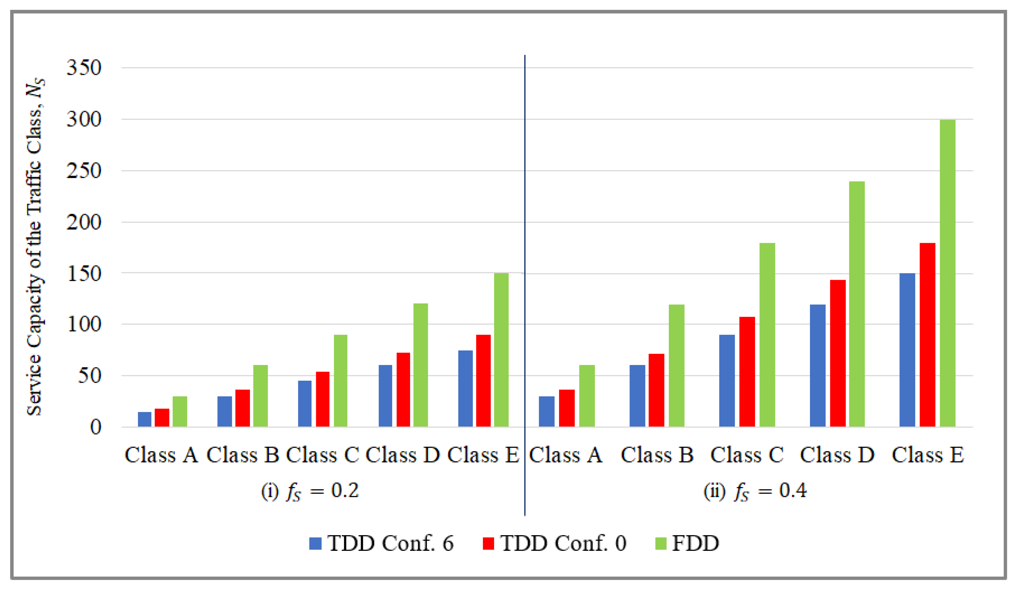
6.1. Multi-Service Adaptive SPS Algorithm

Figure 10 compares the Cumulative Distribution Functions (CDF) for the different runs for traffic class A which is the most delay sensitive class with a PDB of 50 ms where the request inter-arrival gap is exponentially distributed with the mean 1 / λ S equal to the PDB. From Figure 9, it is observed that increasing the value of f S increases the service capacity N S . However, in Figure 10, it is obvious that the capacity increment comes at a cost of increase in delay. Since we are interested in keeping the delay only under the class-specific PDB, not decreasing the overall delay, the value of f S can be maximized as long as the target percentage of packets meet their delay budgets. It can be deduced that, f S = 0.4 , which indicates an SPS period T S P S , A = 20 ms is the optimum configuration with 100% class A packets meeting their delay constraints and also supports more capacity (6 class A UEs) than f S = 0.2 (3 class A UEs). Larger values of f S = 0.6 and 0.8 are not satisfactory with only 77% and 39.5% class A packets meeting their delay budgets. The dynamic scheduler serves 95% class A packets within their delay budgets.
Figure 11 again compares the uplink delay CDFs for class A traffic where the request inter-arrival gap is exponentially distributed with the mean 1 / λ S equal to 20% of the PDB i.e., 10 ms . For high request arrival rates, the control channel constraints for the dynamic scheduler comes into play and the peaks in requests often causes PDCCH saturation momentarily. This saturation points builds up queues at the UEs which may be observed in some dynamically scheduled packets experiencing very high delays. Figure 11 shows the delay values in logarithmic scale due to such large variations in delay. The higher request arrival rate requires more PRBs per SPS allocation. The higher the value of f S , also more packets are accumulated in the device buffers. If the required resources are higher than the adaptive PRB ceiling, then all the buffered packets cannot be served at one go and some packets need to wait/be discarded. This causes the adaptive SPS algorithm to fail to meet the PDB in some cases with high request arrival rate, especially for f S = 0.6 and 0.8 . However, it is still possible to satisfy 99% class A packets’ delay constraints with f S = 0.4 .
Again, Figure 12 compares the Cumulative Distribution Functions (CDF) for the different scheduling schemes for traffic class E which has the longest PDB value of 250 ms where the request inter-arrival gap is exponentially distributed with the mean 1 / λ S equal to the PDB. For class E traffic as well, f S = 0.4 offers optimum results with 100% packets meeting their delay constraints and also more capacity (30 class E nodes) than f S = 0.2 (15 class E nodes). We further notice that, for f S = 0.6 , the performance of the adaptive SPS for class E traffic is better (90% meeting PDB) than that for class A (77% meeting PDB in Figure 10). Since the dynamic scheduler does not consider delay budget values for scheduling decisions, the delay values for class E packets are much lower than their PDB i.e., 250 ms. As the request inter-arrival gap for class E traffic is much less than class A traffic, there is less packet queuing in class E UEs in the dynamic case, allowing the class E packets to achieve much lower delay than they actually can tolerate. The adaptive SPS utilizes the PDB value to modulate T S P S , E by controlling f S , which provides optimum delay performance as per the specific requirements of class E.
The uplink delay CDFs for class E traffic are shown in Figure 13 where the mean 1 / λ S equal to 20% of the PDB i.e., 50 ms . For 5 times higher request arrival rate, the delay experienced by the packets for the dynamic scheduler is higher than it was in Figure 12. But it is interesting to note that still 86% class E packets meet their PDB value of 250 ms whereas in the case of class A traffic with similar intensity (Figure 11), only 32% dynamically scheduled packets meet their PDB. Therefore, for dynamic scheduling, there is more probability of meeting the delay constraints for traffic with higher delay budget values. This observation is later utilized to prioritize between traffic classes for appropriate scheduling decisions. In Figure 13, the higher resource requirements per allocation and longer values of T S P S , E cause performance degradation for f S = 0.6 and 0.8 . Nonetheless, 95% of the class E packets satisfy their delay budget values for f S = 0.4 .
Figure 14 compares the performance of the multi-service adaptive SPS algorithm and the dynamic scheduler. For all the simulation runs, f S = 0.4 is selected for optimum delay performance, so the value of T S P S , S = 0.4 T P D B , S is fixed for each traffic class S. The mean request inter-arrival gap 1 / λ S is varied from 2 T S P S , S to 0.5 T S P S , S . Hence the horizontal axis shows the mean request arrivals per SPS period increasing from 0.5 to 2. The total number of M2M UEs for 5 traffic classes is 90, where each class is assigned the number of UEs equal to their full capacity N S for f S = 0.4 .
As observed for the adaptive SPS algorithm, more than 96% delay budget satisfaction is achieved even when the request arrival rate is increased up to 2 / T S P S , S while for the dynamic scheduler, only about 51% packets meet their respective delay budgets.
Figure 15 shows the uplink data channel i.e., PUSCH and downlink control channel i.e., PDCCH utilization comparisons for the adaptive SPS and the dynamic scheduler. As expected from the virtue of semi-persistent scheduling, the adaptive scheduler shows much lower PDCCH utilization values than the dynamic one for all simulation runs, only increasing slightly from 16% to 27% mean value. The Radio Resource Control (RRC) messages, MCS updates and re-transmissions still require explicit PDCCH grants, making the PDCCH utilization higher with increasing arrival rates. The dynamic scheduler consumes PDCCH resources for every allocation thus increasing rapidly with rising arrival rate having more than 50% mean PDCCH utilization for maximum arrival rate.
From the mean PUSCH utilization values showed in Figure 15, it is interesting to observe that initially for low arrival rates i.e., λ S < 1 / T S P S , S , the resource utilization was slightly higher for the adaptive scheduler than the dynamic one. This is due to the request inter-arrival gap being greater than the gap between successive SPS allocations. As per Equation (1), at least 1 PRB is consumed per adaptive SPS allocation even if the latest BSR was zero. This trade-off is required to keep the eNodeB updated about the UE buffer status and keep the SPS ongoing as new data arrives at the UE, without requiring new connection establishment/control signaling. However, if the SPS period is much shorter than the request inter-arrival gap (which is the case here initially), often there is no data to send at the device and 1 PRB is wasted without sending any actual data. So dynamic scheduling has an advantage at this point since it does not give any grant for such cases. However, as the arrival rate increases ( λ S > 1 / T S P S , S ), the adaptive scheduler can utilize the resources better than the dynamic since it allows accumulation of more packets at the UE buffer before they can be transmitted. In this way, the allocated PRBs can be fitted better with the buffered packets and more bits/PRB can be transmitted to ensure lower utilization hence higher efficiency.
So far, we simulated the multi-service adaptive SPS algorithm for 5 traffic classes allocated in 5 available uplink subframes per frame. Now we introduce new traffic class F (as defined in Table 4). As we gradually add 10 to 60 UEs from traffic class F in the simulation, the total number of M2M UEs in the system is increased from 100 to 150.
Figure 16 shows the delay budget performance of the adaptive SPS and the dynamic scheduler as we add more class F UEs in the system.
Although the adaptive scheduler still supports more packets to meet their delay budget than the dynamic one for increasing number of UEs, its performance gradually degrades from 67% QoS satisfaction for 100 UEs to 37% for 150 UEs. To address this issue, we developed the functionality to pre-empt SPS traffic classes with higher delay budget to admit newly arriving SPS traffic with smaller delay budget. So the pre-emptive adaptive SPS prioritizes class F traffic because it has a lower PDB of 100 ms than the previously allocated traffic classes C, D and E. The pre-emption is done starting with the traffic class with the highest PDB and allocations are pre-empted until there is enough room to support all the UEs of the higher priority traffic class. When only 10 class F UEs are added into the system, class E UEs are pre-empted and those UEs are scheduled dynamically. Afterwards, when more UEs from class F are added, gradually the equivalent number of UEs are pre-empted from class D and C. By this mechanism, it is ensured that the overall percentage of packets meeting their own delay budgets is increased as we can see clearly in Figure 16 for the pre-emptive adaptive scheduler performance.
Figure 17 compares the mean PUSCH utilization values for the adaptive SPS, dynamic and pre-emptive adaptive SPS algorithms.
Both of the adaptive schedulers shows similar PUSCH utilization for increasing number of UEs and reaches channel capacity saturation for 150 M2M UEs. On the other hand, the PUSCH utilization of the dynamic scheduler reaches a plateau for 140 UEs and does not increase further. So the adaptive schedulers clearly exhibit more capacity in the data channel with the pre-emptive adaptive SPS offering even better delay performance by prioritizing among SPS traffic classes.
Figure 18 compares the mean PDCCH utilization values for the three scheduling schemes. The pre-emptive adaptive SPS shows slightly higher PDCCH utilization than the basic adaptive SPS, which is due to the pre-emptive version scheduling more requests dynamically to prioritize class F traffic. Yet both the adaptive SPS schemes achieve much lower control channel utilization than the dynamic one.
Full dynamic scheduling requires excessive control signaling that saturates the PDCCH channel for 140 UEs in the simulation. Beyond this point, the PUSCH utilization for the dynamic scheduler does not increase more than 83% (as seen in Figure 17) due to the unavailability of enough PDCCH resources to transmit the uplink grants. Therefore, the capacity bottleneck of the dynamic scheduler for M2M traffic comes from the control channel, by overcoming which the adaptive schedulers can exploit the full capacity of the data channel.

6.2. DRX Power Saving with Adaptive SPS

The simulation results for DRX power savings with adaptive SPS algorithm for 4 traffic classes are discussed henceforth. For demonstration purposes, we deploy 2 example values of f S in our model, f S = 0.4 and f S = 0.8 .  Figure 19 shows the percentage of packets meeting their respective delay budget values as total number of UEs increase from 40 to 120. Initially, the dynamic scheduler performs well but as the number of UEs increased beyond 60, more packets fail to be delivered within their delay budgets. For the adaptive SPS algorithm, the delay performance is satisfactory with both configurations. For f S = 0.4 , 98.8% packets meet their delay budget for 120 UEs, while for f S = 0.8 , the value is 93%. The reason for performance degradation in case of f S = 0.8 is due to the PRB ceiling restriction which causes some packets in the UE buffer to wait for the next SPS opportunity.
As shown in Figure 20, the UE power consumption values are averaged over 1000 TTIs for 4 classes of traffic. It is clear from the results that the adaptive SPS with DRX functionality saves significant amount of UE power for all classes of traffic. The high power consumption with the dynamic scheduler is due to the UEs remaining mostly in active state. For, f S = 0.8 , more power saving is achieved because of longer sleep periods. Class A UEs are the most power consuming due to their higher frequency of packet arrival.
Figure 21 compares the channel utilization values which shows the dynamic scheduler having high control signaling load with 100% PDCCH saturation for 120 UEs. The PDCCH saturation with dynamic scheduler causes the delay performance degradation as seen in Figure 19. The adaptive SPS schedulers have very low PDCCH utilization, only requiring control signaling for initial grants and occasional updates of MCS and re-transmissions.
Figure 21 also shows the PUSCH utilization comparison where the three schedulers have similar utilization values. The adaptive SPS schedulers have slightly higher data channel consumption because of semi-persistently allocating minimal resources where occasionally the UE might have no data to be sent. The predictive allocation scheme for f S = 0.8 might also over-allocate sometimes which make the PUSCH utilization higher for it. This is a small trade-off for the SPS schedulers to save on control overhead and power consumption. If there is data channel resource constraint, then the conservative/reactive allocation scheme is more suitable than the predictive scheme for adaptive SPS.

7. Conclusions

In this paper, we presented a new scheduling algorithm for supporting M2M traffic with different arrival patterns and delay tolerances in the LTE networks. The concept of semi-persistent scheduling was utilized to alleviate the heavy signaling load of dynamic scheduling that is one of the major concerns for small payload sizes of mass M2M device-initiated transmissions. Moreover, we introduced adaptation of the semi-persistent allocations based on buffer information to suit the needs of variable burst sizes and modulated the allocation periods with a control parameter and showed their impacts on the QoS. The observations can be utilized to customize the algorithm thus ensuring higher capacity and efficiency for target-specific M2M traffic classes. We also designed a pre-emptive feature to prioritize highly delay sensitive M2M traffic by the SPS algorithm and divert more delay tolerant traffic to dynamic scheduling.
With the adaptive SPS, the M2M UEs do not require to seek or process PDCCH grants before every uplink transmissions thus they can reduce power consumption which is an important requirement for cost-effective M2M communication. To realize this goal, we also coupled the adaptive SPS algorithm with DRX functionality for M2M traffic. The joint algorithm reduces UE power consumption by uninterrupted sleep and the sleep periods can be further increased by modifying a control parameter and using prediction-based larger allocations. These parameters can be further investigated to provide optimal solutions for diverse M2M scenarios. The results have shown significant reduction in the UE power consumption values as well as downlink control signaling with satisfactory QoS performance for M2M traffic as compared to the LTE dynamic scheduler.
A further enhancement of our algorithm can be device-to-device allocation forwarding in cases where an M2M UE has already been assigned an adaptive SPS allocation but it does not require that any more. Such UEs can forward their allocations to a nearby UE that can utilize it without the need of new connection establishment and grant procedure. We also plan to support different ranges of desired QoS guarantees by allocating a range of the control parameter and adaptation functions for different M2M applications with diverse constraints and urgency levels. The adaptive SPS algorithm for low power devices has substantial importance for M2M communications and will be explored in depth in our future works.

Author Contributions

Conceptualization, N.A., J.B. and J.Y.K.; Data curation, N.A.; Formal analysis, N.A.; Supervision, J.Y.K.; Writing—original draft, N.A.; Writing—review & editing, J.B. and J.Y.K. All authors have read and agreed to the published version of the manuscript.

Funding

This research received no external funding.

Institutional Review Board Statement

Not applicable.

Informed Consent Statement

Not applicable.

Data Availability Statement

Not applicable.

Conflicts of Interest

The authors declare no conflict of interest.

References

  1. Borgia, E. The Internet of Things vision: Key features, applications and open issues. Comput. Commun. 2014, 54, 1–31. [Google Scholar] [CrossRef]
  2. Biral, A.; Centenaro, M.; Zanella, A.; Vangelista, L.; Zorzi, M. The challenges of M2M massive access in wireless cellular networks. Digit. Commun. Netw. 2015, 1, 1–19. [Google Scholar] [CrossRef]
  3. 3GPP. 3GPP TS 22.368 V16.0.0 Technical Specification Group Services and System Aspects; Service Requirements for Machine-Type Communications (MTC); Stage 1 (Release 16); 3rd Generation Partnership Project: Sophia Antipolis, France, 2020. [Google Scholar]
  4. 3GPP. 3GPP TR 45.820 V0.3.0 Technical Specification Group GSM/EDGE Radio Access Network; Cellular System Support for Ultra Low Complexity and Low Throughput Internet of Things; Release 13; 3rd Generation Partnership Project: Sophia Antipolis, France, 2015. [Google Scholar]
  5. Cheng, M.Y.; Lin, G.Y.; Wei, H.Y.; Hsu, A.C.C. Overload control for Machine-Type-Communications in LTE-Advanced system. IEEE Commun. Mag. 2012, 50, 38–45. [Google Scholar] [CrossRef]
  6. Zhou, K.; Nikaein, N.; Knopp, R.; Bonnet, C. Contention Based Access for Machine-Type Communications over LTE. In Proceedings of the 2012 IEEE 75th Vehicular Technology Conference (VTC Spring), Yokohama, Japan, 6–9 May 2012; pp. 1–5. [Google Scholar] [CrossRef]
  7. Lin, T.M.; Lee, C.H.; Cheng, J.P.; Chen, W.T. PRADA: Prioritized Random Access With Dynamic Access Barring for MTC in 3GPP LTE-A Networks. IEEE Trans. Veh. Technol. 2014, 63, 2467–2472. [Google Scholar] [CrossRef]
  8. Brown, J.; Khan, J.Y. Key performance aspects of an LTE FDD based Smart Grid communications network. Comput. Commun. 2013, 36, 551–561. [Google Scholar] [CrossRef] [Green Version]
  9. Andrade, T.P.C.d.; Astudillo, C.A.; Fonseca, N.L.S.d. Allocation of Control Resources for Machine-to-Machine and Human-to-Human Communications Over LTE/LTE-A Networks. IEEE Internet Things J. 2016, 3, 366–377. [Google Scholar] [CrossRef] [Green Version]
  10. Shariatmadari, H.; Ratasuk, R.; Iraji, S.; Laya, A.; Taleb, T.; Jantti, R.; Ghosh, A. Machine-type communications: Current status and future perspectives toward 5G systems. IEEE Commun. Mag. 2015, 53, 10–17. [Google Scholar] [CrossRef] [Green Version]
  11. Wang, H.; Jiang, D. Performance Comparison of Control-Less Scheduling Policies for VoIP in LTE UL. In Proceedings of the 2008 IEEE Wireless Communications and Networking Conference, Las Vegas, NV, USA, 31 March–3 April 2008; pp. 2497–2501. [Google Scholar] [CrossRef]
  12. 3GPP. 3GPP TS 36.300 V11.5.0 Evolved Universal Terrestrial Radio Access (E-UTRA) and Evolved Universal Terrestrial Radio Access Network (E-UTRAN); Overall Description; Stage 2, Release 11; 3rd Generation Partnership Project: Sophia Antipolis, France, 2013. [Google Scholar]
  13. Afrin, N.; Brown, J.; Khan, J.Y. An Adaptive Buffer Based Semi-persistent Scheduling Scheme for Machine-to-Machine Communications over LTE. In Proceedings of the 2014 Eighth International Conference on Next Generation Mobile Apps, Services and Technologies, Oxford, UK, 10–12 September 2014; pp. 260–265. [Google Scholar] [CrossRef]
  14. Afrin, N.; Brown, J.; Khan, J.Y. Performance evaluation of an adaptive semi-persistent LTE packet scheduler for M2M communications. In Proceedings of the 2014 8th International Conference on Signal Processing and Communication Systems (ICSPCS), Gold Coast, QLD, Australia, 15–17 December 2014; pp. 1–7. [Google Scholar] [CrossRef]
  15. Afrin, N.; Brown, J.; Khan, J.Y. Design of a buffer and channel adaptive LTE semi-persistent scheduler for M2M communications. In Proceedings of the 2015 IEEE International Conference on Communications (ICC), London, UK, 8–12 June 2015; pp. 5821–5826. [Google Scholar] [CrossRef]
  16. Brown, J.; Afrin, N.; Khan, J.Y. Delay Models for Static and Adaptive Persistent Resource Allocations in Wireless Systems. IEEE Trans. Mob. Comput. 2016, 15, 2193–2205. [Google Scholar] [CrossRef]
  17. Ratasuk, R.; Zhou, D.; Sinha, R. LTE-M Coexistence Within 5G New Radio Carrier. In Proceedings of the 2020 IEEE 3rd 5G World Forum (5GWF), Bangalore, India, 10–12 September 2020; pp. 224–228. [Google Scholar] [CrossRef]
  18. Le, T.K.; Salim, U.; Kaltenberger, F. An Overview of Physical Layer Design for Ultra-Reliable Low-Latency Communications in 3GPP Releases 15, 16, and 17. IEEE Access 2021, 9, 433–444. [Google Scholar] [CrossRef]
  19. Lien, S.Y.; Chen, K.C. Massive Access Management for QoS Guarantees in 3GPP Machine-to-Machine Communications. IEEE Commun. Lett. 2011, 15, 311–313. [Google Scholar] [CrossRef] [Green Version]
  20. Lien, S.Y.; Chen, K.C.; Lin, Y. Toward ubiquitous massive accesses in 3GPP machine-to-machine communications. IEEE Commun. Mag. 2011, 49, 66–74. [Google Scholar] [CrossRef]
  21. Gotsis, A.G.; Lioumpas, A.S.; Alexiou, A. Evolution of packet scheduling for Machine-Type communications over LTE: Algorithmic design and performance analysis. In Proceedings of the 2012 IEEE Globecom Workshops, Anaheim, CA, USA, 3–7 December 2012; pp. 1620–1625. [Google Scholar] [CrossRef]
  22. Gotsis, A.G.; Lioumpas, A.S.; Alexiou, A. Analytical modelling and performance evaluation of realistic time-controlled M2M scheduling over LTE cellular networks. Trans. Emerg. Telecommun. Technol. 2013, 24, 378–388. [Google Scholar] [CrossRef]
  23. Hussain, F.; Anpalagan, A.; Vannithamby, R. Medium access control techniques in M2M communication: Survey and critical review. Trans. Emerg. Telecommun. Technol. 2017, 28, e2869. [Google Scholar] [CrossRef]
  24. Wu, J.; Zhang, T.; Zeng, Z. Performance analysis of discontinuous reception mechanism with web traffic in LTE networks. In Proceedings of the 2013 IEEE 24th Annual International Symposium on Personal, Indoor, and Mobile Radio Communications (PIMRC), London, UK, 8–11 September 2013; pp. 1676–1681. [Google Scholar] [CrossRef]
  25. Tung, L.P.; Wang, L.C.; Hsueh, C.W.; Chang, C.J. Analysis of DRX power saving with RRC states transition in LTE networks. In Proceedings of the 2015 European Conference on Networks and Communications (EuCNC), Paris, France, 29 June–2 July 2015; pp. 301–305. [Google Scholar] [CrossRef]
  26. Zhang, Z.; Zhao, Z.; Guan, H.; Du, L.; Tan, Z. Performance analysis of an adaptive DRX mechanism with flexible short/long cycle switching in LTE network. In Proceedings of the 2013 5th IEEE International Symposium on Microwave, Antenna, Propagation and EMC Technologies for Wireless Communications, Chengdu, China, 29–31 October 2013; pp. 27–32. [Google Scholar] [CrossRef]
  27. Ergul, O.; Yilmaz, O.; Koc, A.T.; Akan, O.B. DRX and QoS-aware energy-efficient uplink scheduling for long term evolution. In Proceedings of the 2013 IEEE Global Communications Conference (GLOBECOM), Atlanta, GA, USA, 9–13 December 2013; pp. 4644–4649. [Google Scholar] [CrossRef]
  28. Tung, L.P.; Lin, Y.D.; Kuo, Y.H.; Lai, Y.C.; Sivalingam, K.M. Reducing power consumption in LTE data scheduling with the constraints of channel condition and QoS. Comput. Netw. 2014, 75, 149–159. [Google Scholar] [CrossRef]
  29. 3GPP. 3GPP TS 36.211 V10.7.0 Evolved Universal Terrestrial Radio Access (E-UTRA); Physical Channels and Modulation; Release 10; 3rd Generation Partnership Project: Sophia Antipolis, France, 2013. [Google Scholar]
  30. 3GPP. 3GPP TS 36.321 V10.8.0 Evolved Universal Terrestrial Radio Access (E-UTRA); Medium Access Control (MAC) Protocol Specification; Release 10; 3rd Generation Partnership Project: Sophia Antipolis, France, 2013. [Google Scholar]
  31. 3GPP. 3GPP TSG-RAN WG2 Meeting, R2-071285, DRX Parameters in LTE; 3rd Generation Partnership Project: Sophia Antipolis, France, 2007. [Google Scholar]
  32. Tseng, C.C.; Wang, H.C.; Kuo, F.C.; Ting, K.C.; Chen, H.H.; Chen, G.Y. Delay and Power Consumption in LTE/LTE-A DRX Mechanism with Mixed Short and Long Cycles. IEEE Trans. Veh. Technol. 2016, 65, 1721–1734. [Google Scholar] [CrossRef]
  33. Erceg, V.; Greenstein, L.J.; Tjandra, S.Y.; Parkoff, S.R.; Gupta, A.; Kulic, B.; Julius, A.A.; Bianchi, R. An empirically based path loss model for wireless channels in suburban environments. IEEE J. Sel. Areas Commun. 1999, 17, 1205–1211. [Google Scholar] [CrossRef] [Green Version]
Figure 1. Multi-service traffic classes allocated in different uplink subframes.
Futureinternet 14 00107 g001
Figure 2. Worst case packet delay for traffic class S.
Futureinternet 14 00107 g002
Figure 3. Time and frequency domain multiplexing for two example traffic classes.
Futureinternet 14 00107 g003
Figure 4. Multi-service adaptive Semi-Persistent Scheduling (SPS) algorithm with pre-emptive functionality.
Futureinternet 14 00107 g004
Figure 5. Standard Discontinuous Reception (DRX) mechanism from User Equipment (UE) perspective (uplink only traffic).
Futureinternet 14 00107 g005
Figure 6. DRX state transitions with adaptive SPS.
Futureinternet 14 00107 g006
Figure 7. Time frame of adaptive SPS with DRX.
Futureinternet 14 00107 g007
Figure 8. UE power consumption model.
Futureinternet 14 00107 g008
Figure 9. Service capacity N S of 5 traffic classes in single-class environment.
Futureinternet 14 00107 g009
Figure 10. Delay CDF for traffic class A ( 1 λ S = T P D B , S ).
Futureinternet 14 00107 g010
Figure 11. Delay CDF for traffic class A ( 1 λ S = 0.2 T P D B , S ).
Futureinternet 14 00107 g011
Figure 12. Delay CDF for traffic class E ( 1 λ S = T P D B , S ).
Futureinternet 14 00107 g012
Figure 13. Delay CDF for traffic class E ( 1 λ S = 0.2 T P D B , S ).
Futureinternet 14 00107 g013
Figure 14. Percentage of packets meeting delay budget (90 UEs).
Futureinternet 14 00107 g014
Figure 15. Mean data and control channel utilization (90 UEs).
Futureinternet 14 00107 g015
Figure 16. Percentage of packets meeting delay budget (150 UEs).
Futureinternet 14 00107 g016
Figure 17. Mean data channel utilization with increasing number of UEs.
Futureinternet 14 00107 g017
Figure 18. Mean control channel utilization with increasing number of UEs.
Futureinternet 14 00107 g018
Figure 19. Percentage of packets meeting delay budget with DRX power saving.
Futureinternet 14 00107 g019
Figure 20. Average UE power consumption in mW per TTI.
Futureinternet 14 00107 g020
Figure 21. Comparison of channel utilizations with DRX power saving.
Futureinternet 14 00107 g021
Table 1. Simulation Parameters.
ParameterValue
LTE Configuration3 MHz TDD
Uplink:Downlink ratio5:5
Maximum UE transmission power0.5 W
Maximum eNodeB transmission power5 W
UE reception sensitivity−95 dBm
eNodeB reception sensitivity−123 dBm
UE antenna gain−1 dBi
eNodeB antenna gain15 dBi
SR periodicity10 ms
Uplink control channels2
Channel modelSuburban Erceg, Terrain C [33]
Radio network modelSingle cell, 3 km radius
Adaptive SPS parameters n S = 3 , N P , m a x = 3
M2M traffic modelPoisson arrival process with mean λ S requests/millisecond for traffic class S where λ S is varied for different simulation runs
M2M request sizeMean packet size 10 Bytes (exponentially distributed)
DRX parametersON-timer = 5 ms, Inactivity timer = 50 ms
Table 2. Traffic Model for Multi-service Traffic Classes.
Traffic ClassPDB (ms)
A50
B100
C150
D200
E250
Table 3. Traffic Model for Power Saving with DRX.
Traffic ClassBurst Size (Packets)Mean Arrival Rate (Bursts/s)PDB (ms)
Aexponential (mean 2)4050
B20100
C13.33150
D10200
Table 4. Parameters for New Traffic Class F.
Traffic Class (S)Mean λ S (Requests/ms) T PDB , S (ms) T SPS , F (ms) N S
F0.11004012
Publisher’s Note: MDPI stays neutral with regard to jurisdictional claims in published maps and institutional affiliations.

