
Performance Analysis of DF Relay-Assisted D2D Communication in a 5G mmWave Network


Abstract
:1. Introduction
1.1. Related Works
1.2. Motivation
1.3. Contribution
- (a)
- The bitwise binary XOR operation was executed to encode the message received at the relay node using a carrier frequency of 28 GHz in an uplink Rician fading channel, which resulted in an enhanced SINR with higher throughput. This scheme is rarely used in 5G mmWave networks;
- (b)
- Mode switching was utilized to help reduce user traffic;
- (c)
- The proposed dynamic relay selection (DRS) method selects the optimal DF relays based on the higher sum SINR, lower distance, and higher channel gain of the instantaneous SINR of D2D communication;
- (d)
- The diffused incoherent scattering power as part of the power consumption was considered at the receiver node for the relay mode operating in the mmWave band for a more realistic and accurate analysis of the EE;
- (e)
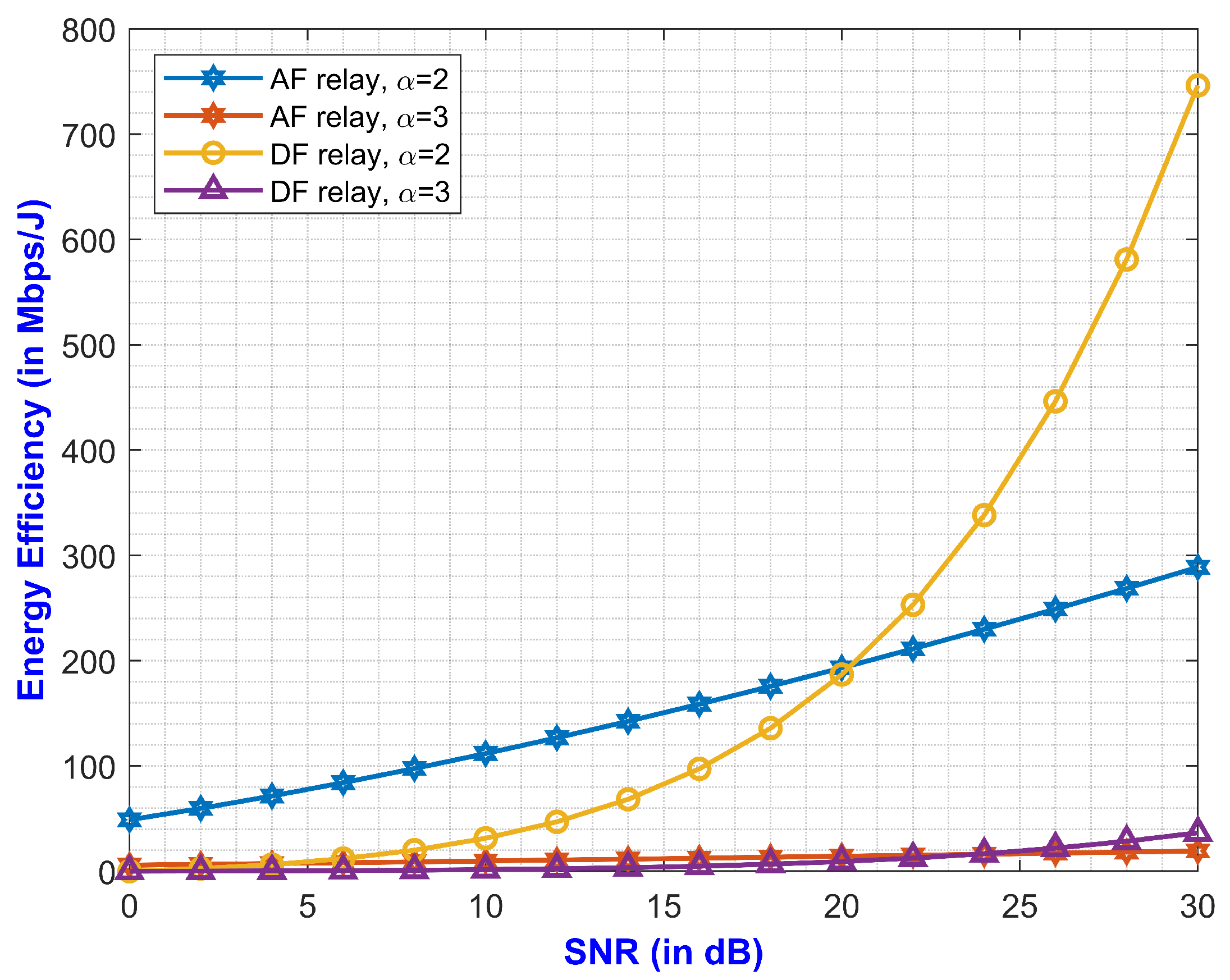
- The performance metric of the coverage probability of D2D communication was derived to demonstrate the efficacy of the communication system. The EE for the proposed DF relay was also compared with the AF relay scheme. Numerical results also validated the efficiency of the proposed work.
1.4. Notations
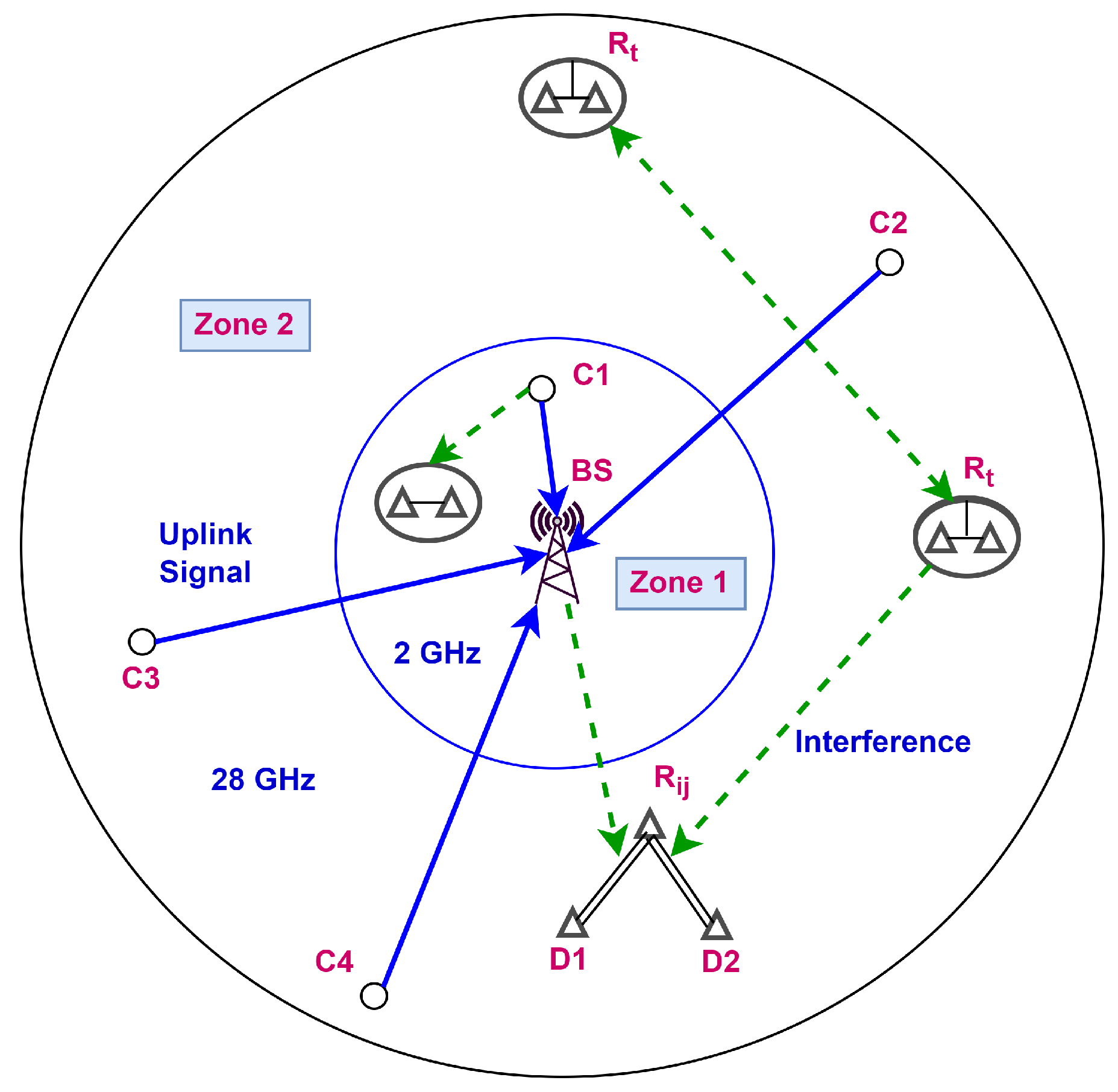
2. System Model
2.1. Information Model
2.2. Path Loss Model
3. Problem Formulation and Analysis
3.1. Zone 1
3.2. Zone 2
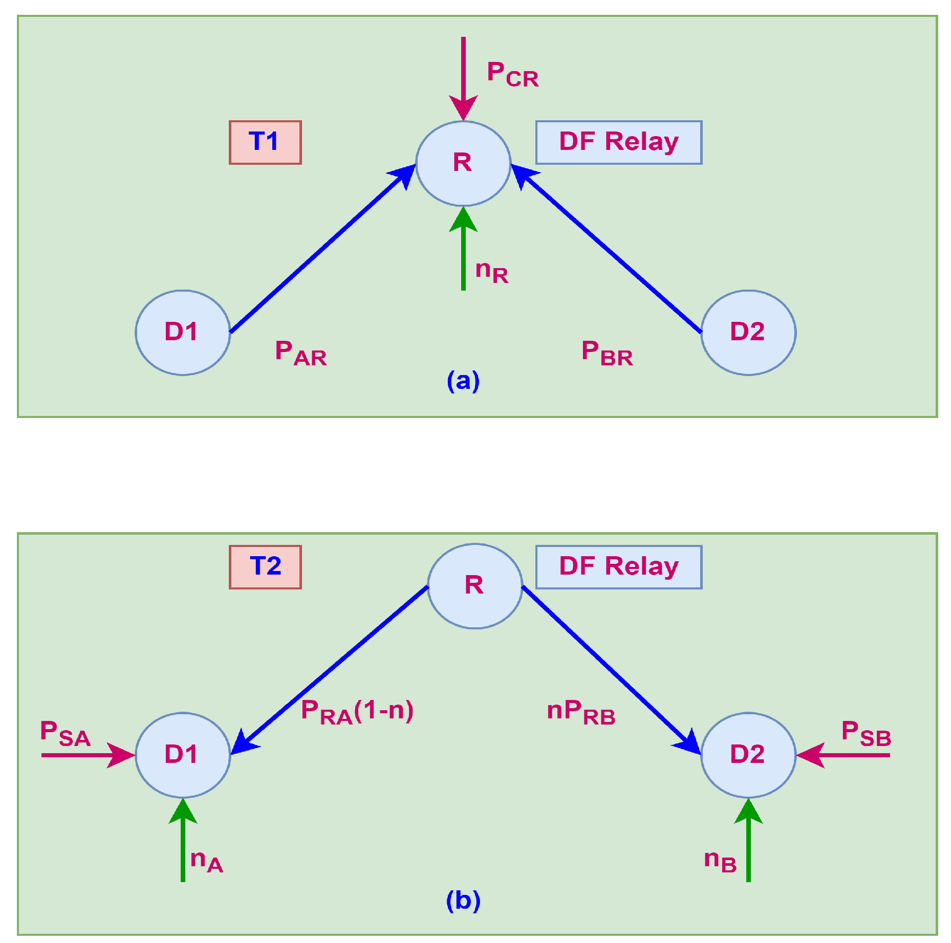
3.2.1. Primary Phase
3.2.2. Secondary Phase
3.3. Performance Analysis
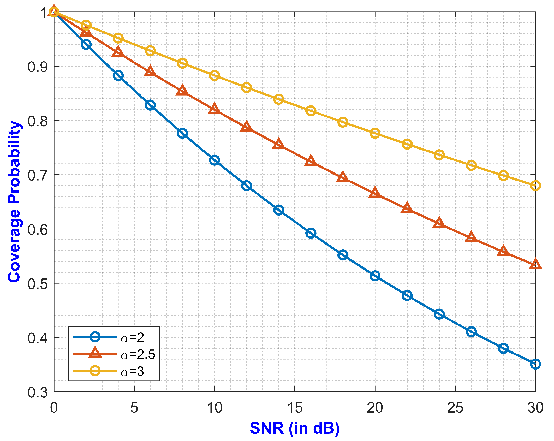
3.3.1. Coverage Probability of D2D Users
3.3.2. Relay Selection
- (1)
- The transmitter D2D user sends a request to all of the relays in its proximity. The respective relay nodes receive the signal and decode it;
- (2)
- The receiver relay sends back the acknowledge signal to user along with the information of the instantaneous sum SINR at the relay node, the path loss attenuation, and the distance between the relay node and D2D users and . The instantaneous sum SINR at the relay node from Equation (24) can be expressed as follows,
- (3)
- User sorts the relays based on the distance between the relay node and D2D users and in increasing order through a binary search method. The relay link exhibiting a higher sum SINR, a lower distance, and higher channel gain is chosen as the relay for D2D communication in Mode 3 as follows,
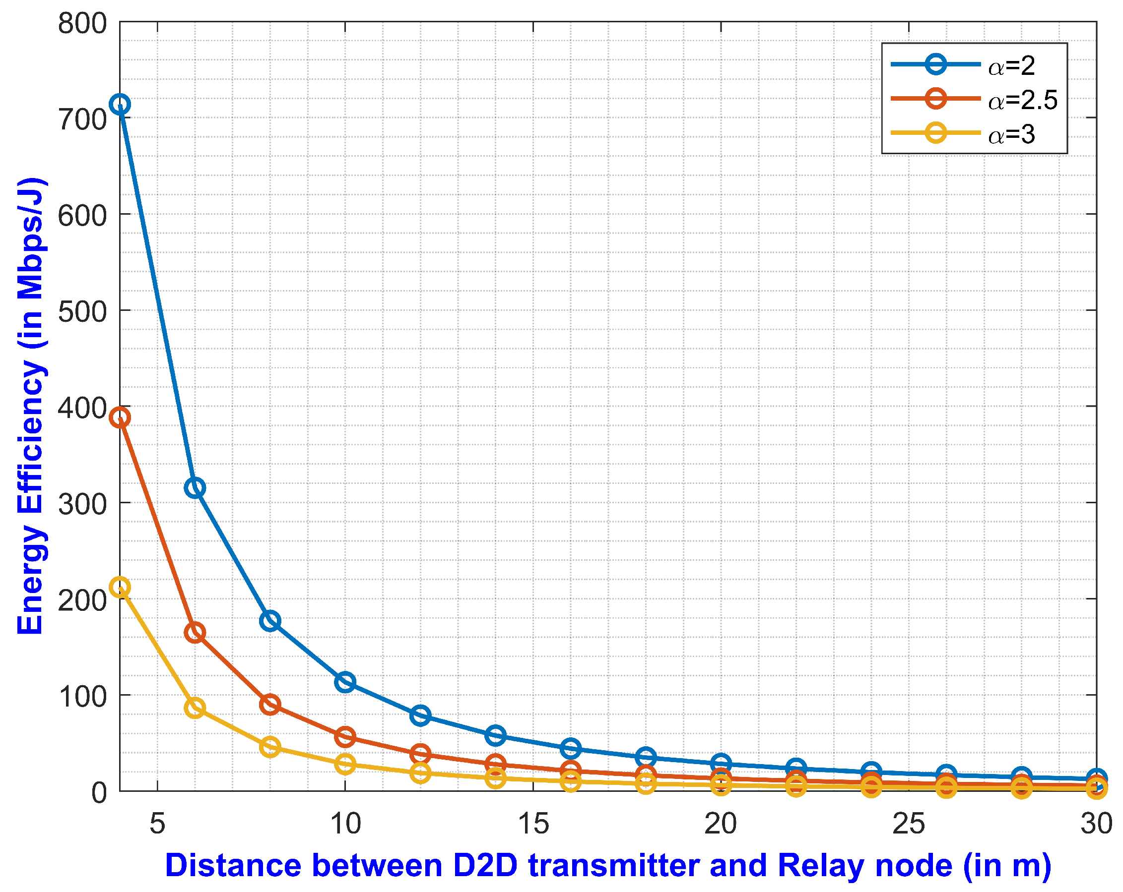
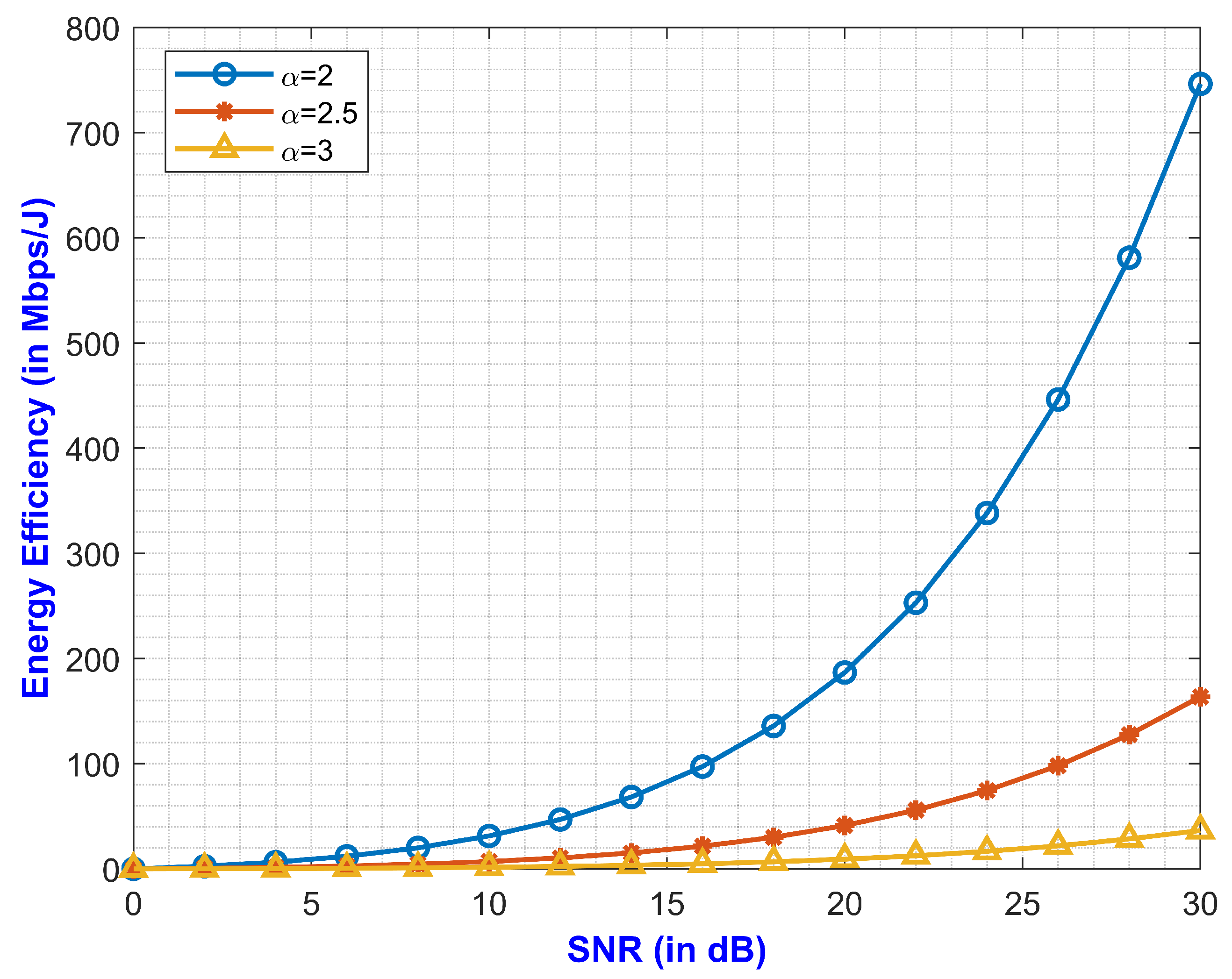
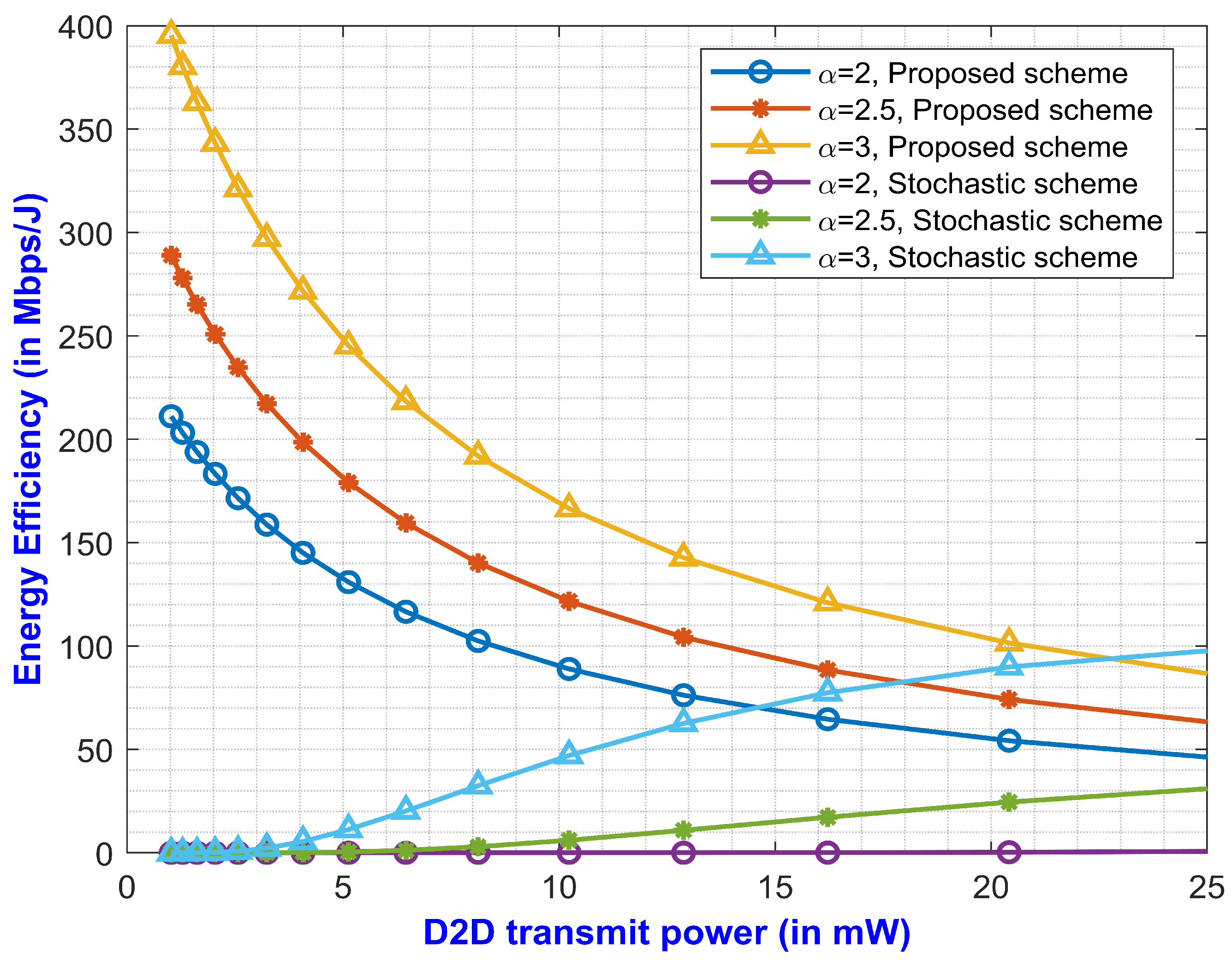
4. Numerical Results and Discussion
5. Conclusions and Future Works
Author Contributions
Funding
Data Availability Statement
Conflicts of Interest
Abbreviations
| D2D | Device-to-device |
| SE | Spectral efficiency |
| EE | Energy efficiency |
| BS | Base station |
| SINR | Signal-to-interference-plus-noise ratio |
| QoS | Quality-of-service |
| DF | Decode-and-forward |
| AF | Amplify-and-forward |
| FDAF | Full-duplex amplify-and-forward |
| CRS | Cooperative relaying strategy |
| QF | Quantization-and-forward |
| Probability distribution function | |
| PPP | Poisson point process |
| FSPL | Free-space path loss |
| CSI | Channel state information |
| DRS | Dynamic relay selection |
References
- Sarma, S.S.; Harza, R.; Mukherjee, A. Symbiosis between D2D communication and Industrial IoT for Industry 5.0 in 5G mmWave cellular network: An interference management approach. IEEE Trans. Ind. Inform. 2021. [Google Scholar] [CrossRef]
- Rappaport, T.S.; Sun, S.; Mayzus, R.; Zhao, H.; Azar, Y.; Wang, K.; Wong, G.N.; Schulz, J.K.; Samimi, M.; Gutier-rez, F. Millimeter wave mobile communications for 5G cellular: It will work! IEEE Access 2013, 1, 335349. [Google Scholar] [CrossRef]
- Sarma, S.S.; Khuntia, P.; Hazra, R. Power control scheme for device-to-device communication using uplink channel in 5G mm-Wave network. Trans. Emerg. Telecommun. Technol. 2021. [Google Scholar] [CrossRef]
- Amodu, O.A.; Othman, M.; Noordin, N.K.; Ahmad, I. Relay-assisted D2D underlay cellular network analysis using stochastic geometry: Overview and future directions. IEEE Access 2019, 7, 115023–115051. [Google Scholar] [CrossRef]
- Wang, R.; Liu, J.; Zhang, G.; Huang, S.; Yuan, M. Energy efficient power allocation for relay-aided D2D communications in 5G networks. China Commun. 2017, 14, 54–64. [Google Scholar] [CrossRef]
- Wu, S.; Atat, R.; Mastronarde, N.; Liu, L. Improving the coverage and spectral efficiency of millimeter-wave cellular networks using device-to-device relays. IEEE Trans. Commun. 2017, 66, 2251–2265. [Google Scholar] [CrossRef]
- Melki, L.; Najeh, S.; Besbes, H. System performance of two-way decode-and-forward relaying assisted D2D communication underlaying cellular networks. In Proceedings of the International Symposium on Signal, Image, Video and Communications (ISIVC), Tunis, Tunisia, 21–23 November 2016; pp. 270–275. [Google Scholar]
- Ni, Y.; Wang, Y.; Jin, S.; Wong, K.K.; Zhu, H. Two-way DF relaying assisted D2D communication: Ergodic rate and power allocation. EURASIP J. Adv. Signal Process. 2017, 2017, 40. [Google Scholar] [CrossRef]
- Singh, I.; Singh, N.P. Coverage and capacity analysis of relay-based device-to-device communications underlaid cellular networks. Eng. Sci. Technol. Int. J. 2018, 21, 834–842. [Google Scholar] [CrossRef]
- Amodu, O.A.; Othman, M.; Noordin, N.K.; Ahmad, I. Transmission capacity analysis of relay-assisted D2D cellular networks with interference cancellation. Ad Hoc Netw. 2021, 117, 102400. [Google Scholar] [CrossRef]
- Han, L.; Zhou, R.; Li, Y.; Zhang, B.; Zhang, X. Power control for two-way AF relay assisted D2D communications underlaying cellular networks. IEEE Access 2020, 8, 151968–151975. [Google Scholar] [CrossRef]
- Kamal, M.; Kader, M.; Islam, S.M.; Yu, H. Device-to-Device Aided Cooperative Relaying Scheme Exploiting Spatial Modulation: An Interference Free Strategy. Sensors 2020, 20, 7048. [Google Scholar] [CrossRef] [PubMed]
- Ma, B.; Shah-Mansouri, H.; Wong, V.W. Full-duplex relaying for D2D communication in millimeter wave-based 5G networks. IEEE Trans. Wirel. Commun. 2018, 17, 4417–4431. [Google Scholar] [CrossRef]
- Gui, J.; Deng, J. Multi-hop relay-aided underlay D2D communications for improving cellular coverage quality. IEEE Access 2018, 6, 14318–14338. [Google Scholar] [CrossRef]
- Raziah, I.; Yunida, Y.; Away, Y.; Muharar, R.; Nasaruddin, N. Adaptive relay selection based on channel gain and link distance for cooperative out-band device-to-device networks. Heliyon 2021, 7, e07430. [Google Scholar] [CrossRef] [PubMed]
- Ghallab, R.; Sakr, A.A.; Shokair, M.; El-Azm, A.A. Electronic relay performance in the inband device-to-device (D2D) communication system. Telecommun. Syst. 2019, 72, 29–39. [Google Scholar] [CrossRef]
- Sarkar, S.; Ghosh, S.C. Relay selection in millimeter wave D2D communications through obstacle learning. Ad Hoc Netw. 2021, 114, 102419. [Google Scholar] [CrossRef]
- Lioumpas, A.; Bithas, P.S.; Hatziefremidis, A. Coordinated tethering for devices with multi-rat capabilities: An algorithmic solution and performance analysis. Phys. Commun. 2019, 37, 100855. [Google Scholar] [CrossRef]
- Bithas, P.S.; Maliatsos, K.; Foukalas, F. An SINR-aware joint mode selection, scheduling, and resource allocation scheme for D2D communications. IEEE Trans. Veh. Technol. 2019, 68, 4949–4963. [Google Scholar] [CrossRef] [Green Version]
- Ju, S.; Kanhere, O.; Xing, Y.; Rappaport, T.S. A Millimeter-Wave Channel Simulator NYUSIM with Spatial Consistency and Human Blockage. arXiv 2019, arXiv:1908.09762. [Google Scholar]
- Sarma, S.S.; Hazra, R. Interference management for D2D communication in mmWave 5G network: An Alternate Offer Bargaining Game theory approach. In Proceedings of the 2020 7th International Conference on Signal Processing and Integrated Networks (SPIN), Noida, India, 27–28 February 2020; pp. 202–207. [Google Scholar]


| Sl. No. | Symbols | Significance |
|---|---|---|
| 1 | Operating frequency | |
| 2 | d | Distance between T and R |
| 3 | Path loss exponent | |
| 4 | Interference due to atmospheric absorption | |
| 5 | Log-normal shadow fading having zero mean | |
| 6 | Standard deviation (in dB) | |
| 7 | Cellular power, D2D power, circuit power, and scattering power, respectively | |
| 8 | Channel gain for D2D and the CU to D2D, respectively | |
| 9 | Channel gain for the CU to the BS and D2D to the BS, respectively | |
| 10 | Distance between D2D and the CU to D2D, respectively | |
| 11 | Distance between the CU to the BS and D2D to the BS, respectively | |
| 12 | AWGN noise at D2D and the CU users, respectively | |
| 13 | AWGN noise at the relay node, D2D A, and D2D B, respectively | |
| 14 | Threshold SINR | |
| 15 | Received power at the relay node from D2D A and D2D users, respectively | |
| 16 | Received power at D2D A and D2D users from the relay node, respectively | |
| 17 | Received power at D2D A and D2D users from the BS and from the CU to the relay, respectively |
| Sl. No. | Symbols | Significance |
|---|---|---|
| 1 | Cell radius | 500 m |
| 2 | Bandwidth | 1 GHz |
| 3 | Frequency (mmWave mode) | 28 GHz |
| 4 | Thermal noise density | −174 dBm/Hz |
| 5 | Cellular power | 30 dB |
| 6 | D2D power (relay mode) | 20 dB |
| 7 | Circuit power | 5 dB |
| 8 | Scattering power | 4 dB |
| 9 | SINR threshold | 0–30 dB |
Publisher’s Note: MDPI stays neutral with regard to jurisdictional claims in published maps and institutional affiliations. |
© 2022 by the authors. Licensee MDPI, Basel, Switzerland. This article is an open access article distributed under the terms and conditions of the Creative Commons Attribution (CC BY) license (https://creativecommons.org/licenses/by/4.0/).
Share and Cite
Sarma, S.S.; Hazra, R.; Chong, P.H.J. Performance Analysis of DF Relay-Assisted D2D Communication in a 5G mmWave Network. Future Internet 2022, 14, 101. https://doi.org/10.3390/fi14040101
Sarma SS, Hazra R, Chong PHJ. Performance Analysis of DF Relay-Assisted D2D Communication in a 5G mmWave Network. Future Internet. 2022; 14(4):101. https://doi.org/10.3390/fi14040101
Chicago/Turabian StyleSarma, Subhra Sankha, Ranjay Hazra, and Peter Han Joo Chong. 2022. "Performance Analysis of DF Relay-Assisted D2D Communication in a 5G mmWave Network" Future Internet 14, no. 4: 101. https://doi.org/10.3390/fi14040101
APA StyleSarma, S. S., Hazra, R., & Chong, P. H. J. (2022). Performance Analysis of DF Relay-Assisted D2D Communication in a 5G mmWave Network. Future Internet, 14(4), 101. https://doi.org/10.3390/fi14040101