1. Introduction
There is a long tradition in many areas of computer science of conceptualizing domains of interest in terms of classes and relationships using a graphical or diagrammatic model. Consider, for example, ER (entity–relationship) diagrams [
1], ubiquitously used in databases, or UML class diagrams [
2], the de facto standard in software engineering for information modeling (when used as conceptual models rather than to represent software components). While often such diagrams are used in a semi-formal way to help communication, it is well-recognized that having precise semantics is actually needed to avoid ambiguities in design.
Interestingly, the very first conceptual languages developed in AI were also graphical, most prominently semantic networks [
3,
4]. However, most work on knowledge representation in AI has focused more on automated reasoning, and has gradually abandoned the graphical conceptual languages in favor of logical languages. This process has started with the famous paper “What’s in a link” [
5], which questioned the inherent ambiguity of graphical conceptual languages of the time, and has continued with the work on KL-ONE [
6], then followed by the introduction of modern description logics (DLs) [
7]. Nevertheless, by the early 1990s, a research program started to emerge: not to disregard, but to try to logically reconstruct graphical conceptual models used in many fields, such as software development and information systems, in order to enable automated reasoning on them [
8,
9,
10]. This program has actually been one of the thrusts towards more and more expressive DLs [
11] that ultimately led to the development of OWL and OWL 2 [
12].
In this paper we bring about a novel contribution to this program: we study a graphical formalism, called
Graphol, which resembles ER and UML class diagrams, but has inherent formal semantics based on DLs and is able to fully capture the ontology language OWL 2. Our proposal comes after a few years of experience in ontology modeling in IT organizations that are knowledgeable on information systems and software engineering, so are familiar with UML and ER, but have only a technological view of ontology languages such as OWL 2 (e.g., [
13,
14,
15]). In these contexts, people often struggle to effectively use the logical formalisms through which ontologies are typically specified, thus slowing down the adoption of semantic technologies.
Graphol mitigates this problem, since it provides IT people with a formalism for specifying and reading ontologies rooted in conceptual modeling languages they are used to. Indeed, its usage has helped substantially in taking up semantic technologies in the industrial use cases [
16,
17,
18,
19,
20,
21].
We point out that we have also developed tools for drawing
Graphol diagrams and translating them into standard OWL 2 ontology format. These tools, however, are not treated in depth in this paper, and we refer the reader to [
22,
23] and to the Github repository of the Eddy ontology editor (
https://github.com/obdasystems/eddy, accessed on 17 January 2022) for the details. Here, instead, we study
Graphol as a language, and focus on its formal properties. Specifically, we give its mathematical semantics, based on DLs, and show that
Graphol diagrams can be translated into OWL 2 ontologies and vice versa. Furthermore, we describe a user evaluation study we carried out to verify the usability of our language. A preliminary version of some of the contributions given in this paper can be found in [
24].
1.1. Introducing the Graphol Language
To obtain an idea of
Graphol and its relation with UML and ER, in
Figure 1 we model a simple situation about students and courses they attend, using a UML class diagram, a
Graphol diagram, and a set of DL axioms, all expressible in OWL 2. We assume that the reader is familiar with UML class diagrams [
2], DLs [
11], and OWL 2 [
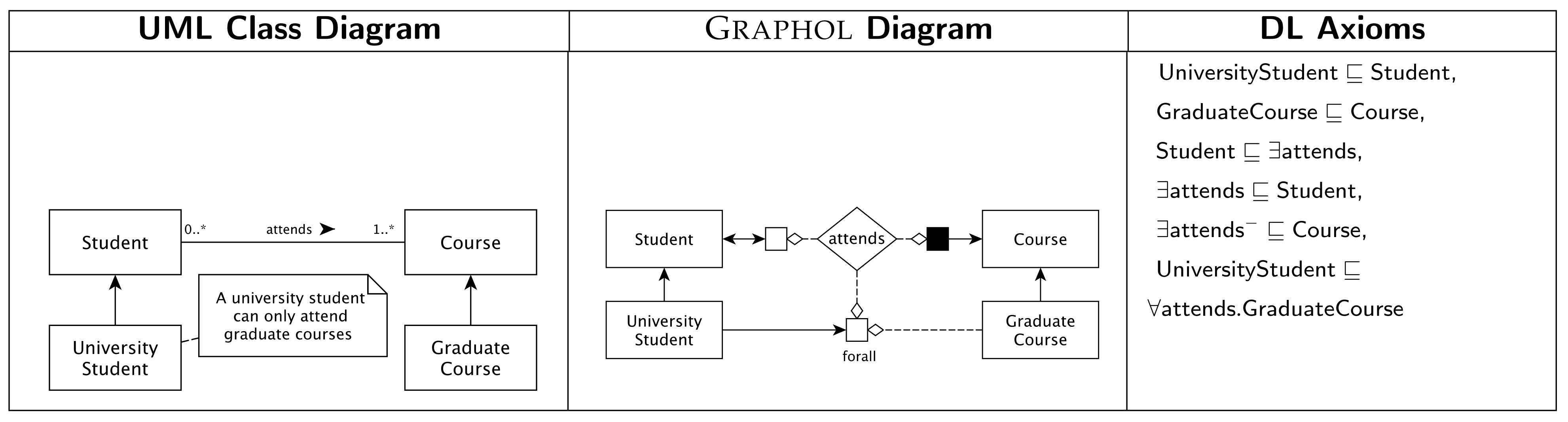
12]. Furthermore, since we adopt the DL notation throughout the paper to express logical axioms, we use the DL terminology for ontology predicates, e.g., we use “concept” to denote a set of objects (i.e., a “class” in OWL parlance), “role” to denote a binary relationship between concepts (i.e., an “ObjectProperty” in OWL parlance), and “attribute” to denote a binary relationship between a concept and a domain of values (i.e., a “DataProperty” relating objects to datatypes in OWL parlance). In all the three versions of the model, we use the same alphabet for predicates. The model states that a student must attend at least a course, that university students are students, that graduate courses are courses, and that university students can only attend graduate courses. One can see that, in
Graphol, concepts are represented through rectangles, analogously to UML, while, as in ER, diamonds are used for roles. Furthermore, solid directed arrows represent inclusions, as in UML and ER (cf. the inclusion between
and
). However, differently from UML and ER, in
Graphol they do not need to involve only named concepts. The use of a diamond to represent a role, i.e., a “node” in the diagram, allows us indeed to depict, in a simple graphical way, concept expressions over the domain and the range of a role, i.e., over its first or second component, by connecting the role to possibly labeled blank and solid boxes, respectively. For example, in
Figure 1, the blank box labeled with “forall” and linked to the role attends denotes the set of individuals that attend only graduate courses. The inclusion drawn between
and this concept expression specifies that a university student can only attend graduate courses, which corresponds to the DL inclusion axiom
. We remark that this property is not directly expressible in a graphical way in UML, where we need to specify it as an external constraint (cf. the note in the diagram), possibly expressed in a logical language such as OCL.
We notice that the idea of extending or adapting UML or ER to capture OWL is indeed not new. However,
Graphol is distinguished from the other proposals with precise semantics, such as [
25,
26,
27,
28,
29] by its ability to capture any OWL 2 ontology in a completely graphical way. Indeed, previous UML-inspired approaches typically require to annotate diagrams with formulas corresponding to complex OWL expressions. Clearly, this hinders both the diagrammatic representation of the ontology and its intuitive understanding. A more in depth discussion on related work is given in
Section 2.
1.2. Paper Organization and Contributions
The rest of the paper is organized as follows. As stated, we first provide an overview of related work on graphical languages for ontology design and visualization. Then, we give some preliminaries on DLs, which we use as formal tool for defining the semantics of
Graphol constructs and for establishing the correspondence between
Graphol and OWL 2, which also has a DL counterpart. Next, in
Section 4, we give the formal syntax of the language (
Section 4.1), its semantics (
Section 4.2), and show its equivalence with OWL 2 (
Section 4.4), i.e., we prove that every
Graphol diagram corresponds to an OWL 2 ontology, and, conversely, that every OWL 2 ontology corresponds to a
Graphol diagram. Then, in
Section 5, we discuss the relationship between
Graphol and UML, and finally, in
Section 6, we provide some user evaluations of our language. Our study shows that
Graphol can be adopted by non-expert modelers introducing only a minimal overhead with respect to the use of standard conceptual languages such as UML and ER, and that this overhead pays off when the UML/ER diagrams need logical annotation to fully capture the ontology of interest. More interestingly, the evaluations we carried out show that
Graphol can be adopted by expert conceptual modelers with ease, greatly facilitating the adoption of a full-fledged ontology language, such as OWL 2, as a formal conceptual modeling language. We conclude the paper in
Section 7.
2. Related Work
The growing use of ontologies in information systems and throughout the semantic web has made effective ontology representation and management a necessity. In this section we provide a brief description of the main tools and graphical languages that have been proposed over the years for these purposes. We point out that many of the proposals we review in the following have been discontinued to date. Nonetheless, they testify the huge effort carried on by the community in this direction and allow to better co-locate our proposal within the state of the art.
For our overview we start from languages adopted in software engineering and database design. As we have already pointed out in the introduction, popular diagrammatic formalisms used in these fields, such as the ER model [
1] and UML class diagrams [
2], have been devised with the primary goal to support design documentation and help communication in the various phases of the development workflow. When used specifically for conceptual modeling, such formalisms are often adopted in a pragmatic way, but a quite-productive line of research has investigated them from a logical perspective with the aim of associating such languages with formal semantics [
8,
9,
10,
30]. In particular, an important effort has been made to exploit DLs to represent and enable automated reasoning in graphical conceptual models used in software development and information systems [
31,
32,
33,
34,
35,
36,
37,
38]. In these works, the relationship between UML class diagrams or ER models and logical languages is studied mostly at theoretical level only. Two exceptions are [
32], where the authors present a tool for translating UML class diagrams into DL ontologies with the aim of verifying their consistency, and [
38], where a prototype tool that provides the DL representation of ER models (more precisely, enhanced entity–relationship models) is presented.
Along with ER and UML, other visual languages have also been employed in the software engineering area, such as, for example, object–role modeling [
39,
40] (ORM and ORM2). ORM provides a graphical notation for modeling and querying business domains in terms of the underlying facts of interest. Unlike ER or UML, ORM treats all facts as relationships, and depicts them through a visual formalism that is meant to be understood by nontechnical users of such domains. In ORM, a model is built around entities, represented through logical predicates, and values, each of which can be described in terms of the types they belong to. Similarly as performed for ER and UML, various research contributions have been made to provide formal semantics to ORM through DLs or even OWL [
41,
42,
43,
44].
As stated, the above-mentioned works have aimed at reconstructing languages such as ER, UML, or ORM under a logical perspective. Ultimately though, such languages have proven to lack the necessary expressive power to capture current ontology formalisms such as OWL 2 or the more expressive DLs.
Some authors have thus proposed to extend the above languages, in particular UML class diagrams, to achieve the expressiveness needed for ontology specification. In [
25,
45] the authors define the ontology definition metamodel (ODM), a UML-based metamodel for defining ontologies. It is grounded in the Meta Object Facility of UML 2.0 (MOF2), which is an extensible model-driven integration framework for defining, manipulating, and integrating metadata and data in a platform-independent manner, and allows to visually represent an ontology through a graph. In [
26,
46], the authors also provide UML profiles which extend ODM with a visual UML syntax for the representation of ontologies in OWL 1 [
47]. However, these works were not continued thereafter towards the new version of the standard language [
12], and updating them in order to incorporate all the features introduced in OW2 2 could be very complex.
The OntoUML modeling language [
27] is also UML-based, but it is tailored towards general conceptual modeling and ontology representation through the ontological guidelines introduced in the unified foundational ontology (UFO), rather than towards providing a visual language for real-world DL ontologies. The principle behind OntoUML is that in order for a modeling language to satisfy the requirements of expressiveness and clarity of a domain, its modeling primitives must be derived from a proper foundational ontology. In other words, a domain-specific ontology must utilize some sort of upper-level ontology as its underlying framework [
48] for fundamental ontological structures such as theory of parts, theory of wholes, types and instantiation, identity, etc.
OWLGrEd (
http://owlgred.lumii.lv/, accessed on 17 January 2022) [
29,
49] is a more recent graphical notation for ontologies based on UML class diagrams: concepts are represented as UML classes, attributes as class attributes, and roles as associations between the classes. OWLGrEd’s UML classes also allow to specify logical expression in Manchester syntax (
http://www.w3.org/TR/owl2-manchester-syntax/, accessed on 17 January 2022) for stating axioms in OWL which are not supported by the graphical notation. OWLGrEd captures OWL 2 completely, and its UML-based notation is quite easy to understand. However, its effectiveness is hindered by the need to use logical formulas in the representation, especially in case of complex ontologies, where the presence of many formulas of this kind can lead to prejudice the intuitive comprehension of the ontology, and by its ambiguous depiction of various kinds of expressions and axioms. Nonetheless, among the related work we discuss, OWLGrEd is the closest in spirit to
Graphol, even though our language allows for a completely graphical representation of OWL 2 ontologies. For this reason, we have considered OWLGrEd in a comparative user evaluation study described in
Section 6.
Below, we turn our attention to languages and tools for the graphical representation of knowledge bases not specifically based on UML or the other diagrammatic languages we discussed so far. Earlier efforts in this direction have typically focused on preliminary explorations of issues and possible solutions for visual representations of DLs. For instance, in [
50], the author discusses general design issues for semantic network formalisms, also providing some details of how such issues may be addressed through an example of a visual language for DLs. Other efforts have focused on investigating the potential of diagrammatic reasoning systems, i.e., visual logics systems which use a graph-based structural form for FOL sentences, as graphical representations of DLs. Examples of such systems are spider and constraint diagrams, as well as conceptual and existential graphs. In [
51], the authors investigate which of these systems is compatible with DLs, concluding that existential graphs are best suited for these purposes. Instead, in [
33], the authors focus on conceptual graphs, and introduce a conceptual graph-based formalism for the representation of knowledge bases. To the best of our knowledge, there have, however, been no further studies nor practical results in the direction of adopting these systems for the visual representation of real-world ontologies.
Among other proposals, we below focus on GrOWL (
http://growl.novasemantics.it/, accessed on 17 January 2022) [
52], and Graffoo (
http://www.essepuntato.it/graffoo/, accessed on 17 January 2022) [
28] and VOWL (
http://vowl.visualdataweb.org/, accessed on 17 January 2022) [
53], which, similar to ours, are specifically tailored to the representation and/or visualization of OWL ontologies. For a more comprehensive classification and comparison of available languages and tools for ontology editing and visualization, we refer the reader to [
54].
GrOWL is a tool for visualizing and editing ontologies, based on the underlying DL semantics of OWL ontologies. GrOWL is able to map both TBox and ABox assertions to a graph-line representation through the use of color, shading, and different shape nodes to encode the properties of the language constructs. Although the core idea behind GrOWL is similar to Graphol’s, the project seems to have been discontinued, and the available documentation does not provide an unambiguous indication of the syntax and semantics of the language. Differently to Graphol, OWLGrEd and Graffoo, GrOWL is also quite distant in nature from classical logical languages such as UML or ER, and this poses further difficulties in its understanding in industrial contexts.
Graffoo is a graphical notation for OWL ontologies, developed using the standard library of the graph editor yEd (
https://www.yworks.com/products/yed, accessed on 17 January 2022). The graphical elements featured in Graffoo are blocks (or nodes) and arcs. Blocks are used to model classes, datatypes, individuals, ontologies, and rules. Arcs are instead used to model assertions, annotation properties, attributes, and roles. Graffoo has been designed for fully capturing OWL 2, but to this aim, some elements of the language are not completely graphical. Indeed, those OWL 2 constructs that cannot be expressed by means of Graffoo’s graphical elements are specified through OWL axioms in Manchester syntax. Therefore, the same arguments given for OWLGrEd about the need of embedding axioms given in a non-graphical way also apply to Graffoo. To the best of our knowledge, there is no editor tailored for Graffoo, but a palette for the yEd editor is available instead.
VOWL (Visual Notation for OWL Ontologies) is a formalism that has been proposed quite recently. It defines a set of graphical primitives and a color scheme, and uses a force-directed graph visualization for the ontology. In VOWL, concepts (i.e., classes in OWL) are represented as circles, and data types are displayed in rectangles. A labeled arrow connecting two circles denotes a role (i.e., an objectProperty in OWL), whereas a labeled arrow connecting a circle to a datatype denotes an attribute (i.e., a dataProperty in OWL). The direction of the arrow establishes the typing of the domain and the range of the property. Cardinality constraints are specified on arrows in the style of UML class diagrams. The mentioned constructs are the basic elements of the representation. A complete list is available at
http://vowl.visualdataweb.org/v2/ (accessed on 17 January 2022). VOWL is able to capture visually a good portion of OWL 2, although some constructs are not part of the actual VOWL visualization. The language is not defined through a formalized syntax, and in the documentation it is not clearly specified which fragment of OWL 2 is completely captured in a visual mode by VOWL. The language has two main implementations: WebVOWL [
55], which is a web tool for ontology visualization, and ProtégéVOWL, a plug-in for the ontology editor Protégé (which, however, does not implement all visual elements defined in the VOWL specification). In both such environments, essentially only ontology visualization features are provided. Indeed, VOWL has been so far proposed as an ontology visualization language rather than a tool for ontology editing. Apart from all the other differences, this last aspect seems to be the one that mainly distinguishes VOWL from our language
Graphol, which is thought for ontology specification.
Besides VOWL and its related visualization environments, there is a number of systems and tools designed for ontology visualization only, which adopt different representation techniques in order to achieve this desired balance. The graphical representation provided by such systems can be either two- or three-dimensional, and adopt visualization strategies as degree of interest [
56], space-filling [
57], context focus [
58], and multiple coordinated views [
59].
Among these systems, we can mention OntoGraf (
http://protegewiki.stanford.edu/wiki/OntoGraf, accessed on 17 January 2022) and OWLViz (
http://protegewiki.stanford.edu/wiki/OntoViz, accessed on 17 January 2022) plug-ins for the popular ontology editor Protégé. The former plug-in uses the layouts library for the Jambalaya plug-in (
http://protegewiki.stanford.edu/wiki/Jambalaya, accessed on 17 January 2022) to provide interactive navigation of the relationships in an ontology through an incremental and dynamic graph-like representation. The latter plug-in provides a node-link representation for viewing and navigating class hierarchies, in which the nodes are classes, and the “is-a”-labeled links represent inclusion relationships between them. It is worthwhile mentioning that both such plug-ins, though popular in the past for quick rendering of the main ontology elements and connection thereof, seem to be currently no longer supported by active development or maintenance. Since tools tailored to ontology visualization do not provide any functionalities for ontology editing, they are slightly far from the objectives of this work; hence, we shall not provide further details on them and instead refer the reader to surveys conducted in [
54,
60,
61] for an in-depth discussion.
We conclude this section by mentioning some non-graphical ontology editing environments. These systems typically include features for editing, browsing, visualizing, importing, and exporting ontologies.
Protégé (
http://protege.stanford.edu/, accessed on 17 January 2022), which we already mentioned before and which is a popular open-source ontology editor and knowledge base framework [
62], is certainly one of the most widely-used non-graphical ontology editors. Protégé supports many languages and formats for ontology development, such as XML schema, RDF(S), and, of course, OWL 2. Moreover, it provides a plug-and-play framework that fosters the development of new functionalities by means of plug-ins (such as the one mentioned above) which can be used to modify both the appearance and the behavior of the system.
The NeOn Ontology Engineering Toolkit (
http://neon-toolkit.org/wiki/Main_Page, accessed on 17 January 2022) is an open-source, multi-platform ontology engineering environment [
63,
64] which is built on the Eclipse platform, and provides a variety of plug-ins for ontology engineering activities such as management, reasoning, and collaboration. In particular, the OntoModel (
http://sourceforge.net/projects/ontomodel/, accessed on 17 January 2022) editor plug-in provides ontology visualization and editing functionalities through a UML-based notation.
The commercial TopBraid Composer by TopQuadrant (
http://www.topquadrant.com/products/TB_Composer.html, accessed on 17 January 2022) is an ontology and RDF data editing environment, developed as an Eclipse plug-in. It offers support for editing ontologies in OWL 2 or RDF and for running SPARQL (
http://www.w3.org/TR/sparql11-query/, accessed on 17 January 2022) queries over them. Furthermore, it provides a visual editor for RDF graphs and for class diagrams, allowing also to generate SPARQL queries directly from the graph view of the ontology.
The OntoStudio Ontology Engineering Environment [
65] is a commercial graphical and textual ontology editor. Similar to TopBraid Composer, OntoStudio is developed as an IDE application using the Eclipse platform, and is extendible through various Eclipse plug-ins. OntoStudio supports RDF(S), OWL-2, and other formats for modeling purposes.
While these systems often attempt to offer some visual representation of ontologies, they are seldom successful in achieving a balance between the amount of information that is shown to the user and the complexity and size of the given representation, which is typically provided in terms of a two-dimensional graph. Furthermore, none of the provided visualizations is based on a graphical language with formal syntax and/or that is able to fully render an OWL 2 ontology.
3. Preliminaries
Description logics (DLs) [
11] are formalisms used to model a domain of interest in a formal way. They are portions of first-order logic that allow for decidable reasoning. In DLs, the domain of interest is represented in terms of
objects (i.e., individuals),
concepts (i.e., abstractions for sets of objects), and
roles (i.e., binary relationships between concepts). Moreover, some DLs consider also
value-domains, denoting sets of values, and
attributes, denoting binary relationships between concepts and value-domains.
We assume to have an alphabet partitioned into and . The former is in turn partitioned into sets of symbols for atomic concepts, atomic roles, atomic attributes, and atomic value-domains. instead contains symbols for constants, and is further partitioned into the sets , which is the set of constants denoting objects, and , which is the set of values.
We now provide syntax and semantics of the DL language of interest in this work. We notice that the DL we provide in this section captures the DL
[
66,
67], i.e., the DL underlying OWL 2. In
Section 4.4, we will discuss which syntactic restrictions to impose to make this language equivalent to
(and so to OWL 2). Concepts, roles, attributes, and value-domains expressions in such DL are defined by the following rules:
where
A denotes an atomic concept,
P an atomic role,
U an atomic attribute,
T an atomic value-domain,
(resp.,
) the
universal concept (resp.,
role,
attribute,
value-domain), and
(resp.,
) the
empty concept (resp.,
role,
attribute,
value-domain).
We call C, R, V, and F a general concept, role, attribute, and value-domain, respectively. In our treatment, such symbols can be used with subscripts. denotes the inverse of an atomic role, while , , , denote the negation of C, R, V, and F, respectively. The expression (resp. ) denotes the domain of a role R (resp. of an attribute V). Instead, the qualified concept existential restriction indicates the domain of R restricted to the class C, i.e., it is an abstraction for the set of objects that R relates to some instance of C. Similarly, denotes the qualified domain of V with respect to a value-domain F, i.e., the set of objects that V relates to some value in F. The concept , also called value restriction, denotes the set of objects that are associated by R only to objects that are instances of C. Similarly, denotes the set of objects that are associated by V only to values in F. The concept is used to express local reflexivity to a role R. denotes the range of an attribute V. Similarly, denotes the range of a role R, which corresponds to the domain of the inverse of R. The set denotes the concept whose instances are denoted by , and, similarly, denotes the value-domain whose instances are denoted by . The symbols ⊓ and ⊔ are the usual and logical connectives. and indicate number restrictions, respectively, at-most restriction and at-least restriction, where n ranges over the nonnegative integers. Finally, denotes a role chain.
The semantics of a DL KB is given in terms of interpretations. An interpretation consists of:
- -
A nonempty interpretation domain , where is the domain of objects, and is the set of values previously introduced (indeed, in every interpretation each value is intepreted by itself);
- -
An
interpretation function that assigns an element of
to each constant in
, and interprets each DL expression as shown in
Table 1.
In the table, denote the interpretation of the constants from the alphabet .
A DL KB is a pair , where is a finite set of intensional assertions, called TBox, and is a finite set of extensional assertions, called ABox. In this paper we focus on the modeling of intensional knowledge, i.e., the TBox, so we will not detail further the form of the ABox (which is the component of the knowledge base maintaining the data).
The TBox assertions we focus on in this work are as follows:
Concept inclusion assertions state that all instances of one concept are also instances of another concept, analogously for role, attribute, and value-domain inclusion assertions.
An interpretation
satisfies a TBox
if it satisfies all inclusions in
, where the notion of satisfaction of an inclusion is as follows:
4. The Graphol Language
In this section we introduce the graphical elements and features of the
Graphol language for ontologies. We will use the popular Pizza (
http://protegewiki.stanford.edu/wiki/Pr4_UG_ex_Pizza, accessed on 17 January 2022) ontology as a running example to illustrate how different expressions and assertions of an ontology are represented in
Graphol, and will use the DL syntax for logical symbols presented in
Section 3 to define the correspondence between
Graphol shapes and their logical meaning.
4.1. Graphol Syntax
The basic principle that guides
Graphol in representing ontologies is that a
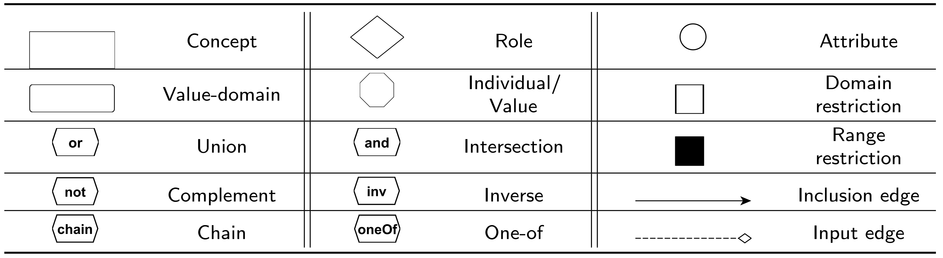
Graphol ontology is a graph whose nodes and edges assume the forms described in
Figure 2.
Nodes can be of two kinds: predicate nodes and operator nodes. Predicate nodes model the terms in the ontology alphabet, i.e., atomic concepts, rendered as rectangles, atomic roles, which are depicted as diamonds, atomic attributes, drawn as circles, atomic value-domains, represented as rounded rectangles, and constants (i.e., individuals and values), denoted through octagons. Each predicate node is associated to a label, which is a name from the ontology alphabet (to distinguish between individual nodes and value nodes, the labels of value nodes are in inverted commas). We note that the shapes used to depict concepts, roles, and attributes are the same as those used in ER diagrams. This choice was made to take advantage of the familiarity that many of the potential users of Graphol may have with this well-known language for conceptual modeling.
The special labels, “Top” and “Bottom”, are reserved for representing universal and empty predicates (i.e, concept, role, attribute, or value-domain), respectively. For example, a diamond with label “Top” represents the universal role (), while a diamond with label “Bottom” represents the empty role (), analogously for concepts, attributes, and value-domains.
Operator nodes are instead used to graphically construct complex expressions. Two shapes for operators are adopted, i.e., the box (which can be either blank or solid), and the hexagon. A blank (resp. solid) box, called domain (resp. range) restriction node, is used to represent restrictions on roles or attributes (resp. their inverses). A box is labeled with one of the following keywords: “exists”, for existential restriction, “forall”, for universal restriction, “self”, for self-restriction, and “” or “”, with x and y positive integers, for min and max cardinality restrictions, respectively. When the label is omitted we intend “exists”. The other operator nodes are denoted by a hexagon and can assume one of the following labels: “or” (union node), “and” (intersection node), “not” (complement node), “inv” (inverse node), “oneOf” (one-of node), and “chain” (chain node).
We observe that
Graphol uses three visual variables [
68] to encode the predicate and constructor nodes. These are (i) the
shape of the nodes, which is used to distinguish between predicate nodes, restriction nodes, and operator nodes, and among the different kinds of predicate nodes; (ii) the
size of the nodes, which allows to clearly discriminate between the quadrilaterals used for concept nodes, value-domain nodes, and restriction nodes; and (iii)
brightness, which is used to distinguish the domain restriction node from the range restriction node.
To avoid encumbering the user in learning the
Graphol syntax, we have chosen to limit the number of different graphical symbols used to depict
Graphol nodes, and to maintain it to around seven, which is the commonly recognized ideal upper bound for software engineering graphical languages [
69]. Indeed, experimental studies demonstrate that a high number of different symbols in a language for software engineering increases the learning difficulty by non-expert users [
70].
Graphol provides two types of edges: inclusion edges, which are solid directed arrow edges (whose target end is denoted by the arrow), used to represent inclusion assertions, and the input edges, which are dashed directed diamond edges (whose target end is denoted by the diamond), used to construct ontology expressions.
An expression in Graphol is a directed acyclic graph, where the nodes can be both operator and predicate nodes and the edges are input edges only. In every Graphol expression there is a single node without outgoing edges, called sink. We give below a formal definition:
Definition 1. AGrapholexpression can be of four types: concept, role, attribute, or value-domain, defined inductively as follows:
- 1.
A concept expression can be:
- -
A concept node (in this case the sink is the node itself);
- -
A domain or range restriction node, with label “exists”, “forall”, “”, or “”, taking as input a role expression and a concept expression (in this case the sink is the domain or range restriction node);
- -
A domain or range restriction node, with label “self”, taking as input a role expression (in this case, the sink is the domain or range restriction node);
- -
A domain restriction node, with label “exists”, “forall”, “”, or “”, taking as input an attribute expression and a value-domain expression (in this case, the sink is the domain restriction node);
- -
A union or intersection node taking as input at least two concept expressions (in this case, the sink is the union or intersection node);
- -
A complement node taking as input a concept expression (in this case, the sink is the complement node);
- -
A one-of node taking as input at least an individual node (in this case, the sink is the one-of node).
- 2.
A role expression can be:
- -
A role node (in this case, the sink is the node itself);
- -
An inverse node taking as input a role expression (in this case, the sink is the inverse node);
- -
A complement node taking as input a role expression (in this case, the sink is the complement node);
- -
A chain node taking as input n role expressions, with , each associated to a label and such that there are no two input edges with the same label (in this case, the sink is the chain node).
- 3.
An attribute expression can be:
- -
An attribute node (in this case, the sink is the node itself);
- -
A complement node taking as input an attribute expression (in this case, the sink is the complement node).
- 4.
A value-domain expression can be:
- -
A value-domain node (in this case, the sink is the node itself);
- -
A range restriction node with label “exists” taking as input an attribute expression (in this case, the sink is the range restriction node);
- -
A union or intersection node taking as input at least two value-domain expressions (in this case, the sink is the union or intersection node);
- -
A complement node taking as input a value-domain expression (in this case, the sink is the complement node);
- -
A one-off node taking as input at least a value node (in this case, the sink is the one-off node).
Intensional assertions in Graphol, as well as in OWL 2 and DLs, are specified as inclusions. Thus, an (inclusion) assertion in Graphol is specified via an inclusion edge from the (sink of the) expression that is included to the (sink of the) expression that it includes. For instance, a concept inclusion assertion between the two concepts and is obtained by linking through an inclusion edge the sink of the Graphol expression of to the sink of the Graphol expression of . Of course, Graphol does not allow to specify inclusion edges between expressions of different types (e.g., a role expression with a concept one).
We finally define a Graphol ontology as a set of Graphol inclusion assertions.
To simplify ontology design and to keep the diagram easier to read, we allow in a
Graphol ontology to have multiple occurrences of the same predicate, obviously all labeled with the same label (which is the name of the predicate). This is particularly useful in those cases in which a predicate occurs in many assertions of the ontology, and so representing such predicate with a single node would lead to having a plethora of incoming or outgoing edges from that node, likely leading to layout issues. We notice that the tool Eddy [
22], which offers an environment for the graphical specification of
Graphol ontologies, provides functionalities for the refactoring of the ontology in case a predicate node is modified, e.g., changes on the predicate node label are automatically propagated to all the replicas of such predicate in the ontology.
4.2. Graphol Semantics
An important desiderata of visual modeling languages is to have clear and precise semantics [
71,
72]. To this aim, here we provide the semantics of
Graphol expressions and assertions by giving their one-to-one correspondence with DL expressions and assertions, which in turn have formal semantics, as discussed in
Section 3.
We start with Graphol expressions, and define a function which takes as input a Graphol expression and computes a DL expression that encodes it.
To formalize , we use to denote the sink of , and the set of Graphol expressions linked to through input edges (of course, this set can be empty). We formally define as follows:
- -
If is a concept, role, attribute, value-domain, or individual/value node with label S, then (we are considering concept, role, attribute, value-domain, individual, and value alphabets as pairwise disjoint. Moreover, if “Top”, we assume that returns the corresponding DL universal predicate, which depends on the form of . Analogously if “Bottom”);
- -
If is a domain restriction node with label “exists” (resp., “forall”, “”, “”), and , where either is a Graphol role expression and is a Graphol concept expression or is a Graphol attribute expression and is a Graphol value-domain expression, then (resp., , , );
- -
if is a range restriction node with label “exists” (resp. “forall”, “”, “”), and , where is a Graphol role expression and is a Graphol concept expression, then (resp. , , );
- -
If is a domain (resp., range) restriction node with label “self”, and , where is a Graphol role expression, then (resp., );
- -
If is a range restriction node with label “exists” and , where is a Graphol attribute expression, then ;
- -
If is a union (resp. intersection or a one-of ) node and , then (resp. , );
- -
if is a complement node and , then ;
- -
If is an inverse node and , then ;
- -
If is a chain node and , where every , where , is a Graphol role expression that is connected to through an input edge with label i, then .
Analogously, to define the semantics of
Graphol inclusion assertions, we use a function
which takes as input one such inclusion
and returns its DL encoding. We use
to denote the
Graphol expression having as sink the node from which the inclusion edge starts in
, and
to denote the
Graphol expression, having as sink the node to which the inclusion edge arrives in
. We thus define
as follows:
. Letting
be a
Graphol ontology, we transform
in a DL ontology
by executing
for every assertion in
. The semantics of
thus are given by the semantics of
, which we have defined in
Section 3.
Table 2 and
Table 3 give examples of application of
to
Graphol expressions of “depth” 0 or 1, i.e., expressions with either only predicate nodes or a constructor node with only predicate nodes as input.
4.3. Shortcuts
We have defined some shortcuts to help the designer in specifying a Graphol ontology. Through such shortcuts it is possible to use a more compact representation of some expressions and assertions that often occur in ontologies. Below we describe them, and provide examples of their use.
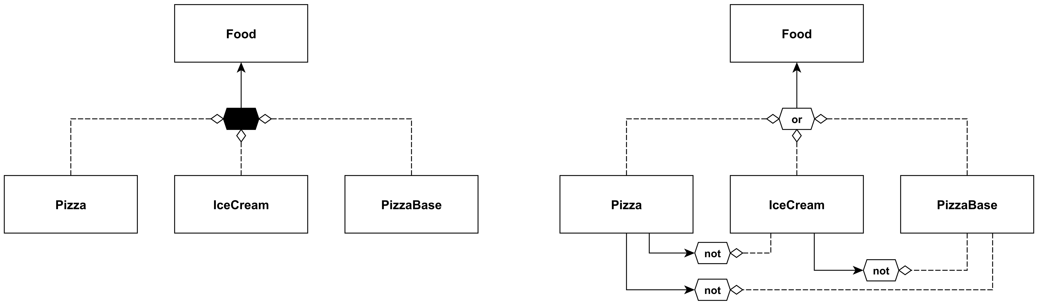
The
disjoint union node is a new type of node, having the shape of a black hexagon, used to represent a disjoint union expression, i.e., a union that at the same time states the disjointness between its arguments. Therefore, through a disjoint union node we also represent negative inclusions over its inputs. This shortcut is particularly useful for defining disjoint concept hierarchies. This is inspired by a similar construct used in the ER model and in UML class diagrams. In
Figure 3, we give an example of one such hierarchy in the two versions, with and without the use of the shortcut.
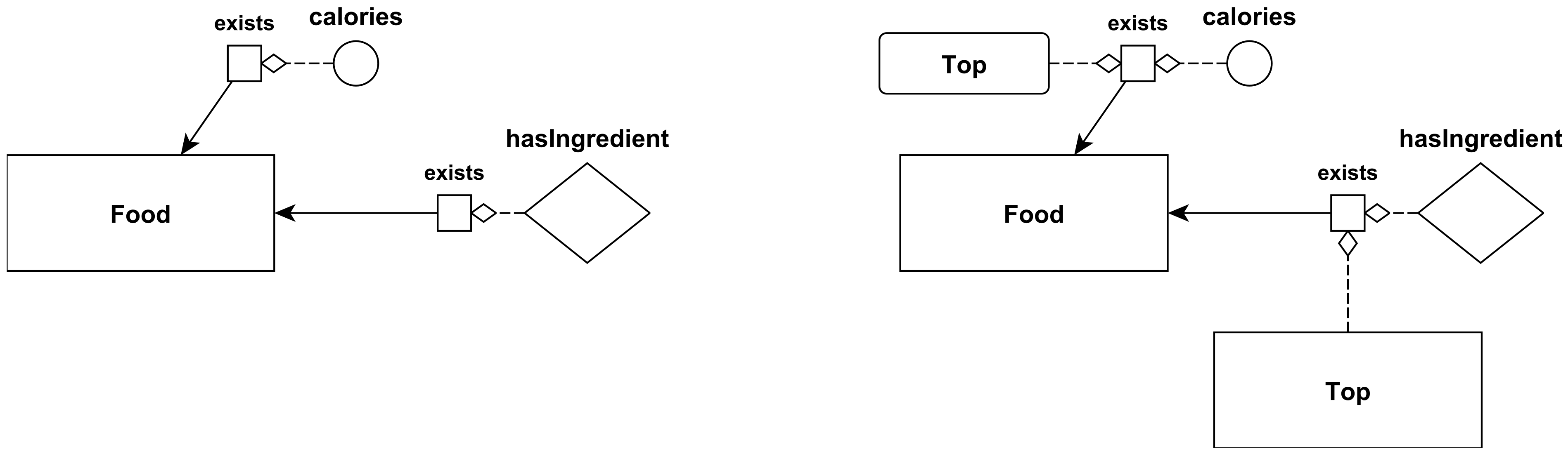
The second shortcut we introduce is a compact notation for the definition of the existential domain or range restriction on a role (resp. attribute) taking as input the universal concept (resp. universal value-domain), which is equivalent to an unqualified existential restriction. Since this is among the most recurring restrictions occurring in ontologies, we allow to omit the universal concept (resp. value-domain) (notice also that the OWL 2 syntax includes redundant constructs such as
owl:ObjectPropertyDomain and
owl:ObjectProperyRange with a similar aim). In other words, to express the unqualified existential restriction on a role or attribute, one can simply link a role or attribute sub-graph to an existential restriction node, as shown in
Figure 4.
Another commonly used assertion in ontologies is the one which specifies that a role R (resp., an attribute V) is globally functional, i.e., (resp., ). Global functionality can be obviously expressed in Graphol through a graphical inclusion assertion. However, in order to provide a more compact representation, we allow to use a blank double-bordered role node (resp., attribute) for a functional role, a solid double-bordered role node for an inverse functional role, and a double-bordered role half blank and half solid for a role that is both functional and inverse functional. Notice that OWL 2 also allows for the use of a compact syntax to specify global functionality (cf. owl:FunctionalObjectProperty).
As an example, in the left-hand side of
Figure 5 we show the standard
Graphol assertion that defines the functionality of a role, and on the right-hand side, the compact notation for a functional role (top left), an inverse functional role (top right), a role that is both functional and inverse functional (bottom left), and, finally, a functional attribute (bottom right).
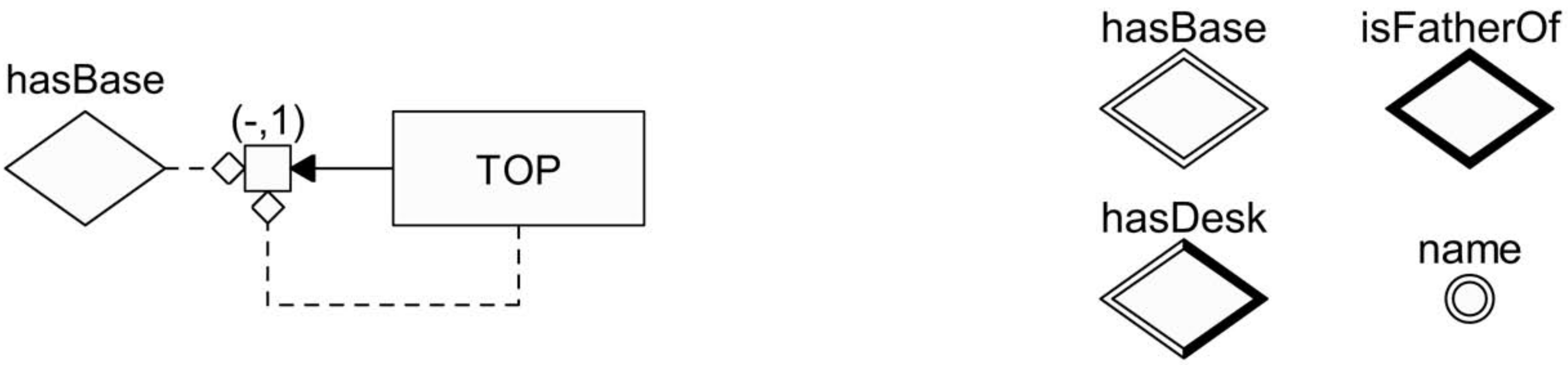
We further notice that two domain (resp. range) restriction nodes with labels and , respectively, and the same input expressions, can be substituted by a single domain (resp. range) restriction node with label and the same inputs. In other terms, and cardinality restrictions can be drawn together. Lastly, if one wishes to define equivalence between two expressions of the same kind, it is possible to use a single inclusion edge with an arrow both on the source end and on the target end instead of two inclusion edges (with the arrow only on the target end) in opposite directions.
4.4. Graphol and OWL 2
In this section we study the relationship between
Graphol and OWL 2 [
73], the W3C standard ontology language. We first study whether
Graphol ontologies can be entirely expressed in OWL 2, and then consider the other way around. In fact, for a formal treatment we identify OWL 2 with its underlying DL
DL [
66,
67] (some OWL 2 features not in
, such as data type restrictions or key axioms, can be modeled in
Graphol by using some additional graphical elements, as reported in the Eddy documentation
https://github.com/obdasystems/eddy (accessed on 17 January 2022). These aspects are not described here for the sake of simplicity).
According to the
Graphol syntax given earlier,
Graphol expressiveness goes slightly beyond that of OWL 2. This allowed us to maintain the formal definition of the syntax of our language simple, without burdening it with too many syntactic categories. Of course, due to this choice, reasoning in full
Graphol is undecidable [
11]. However, by suitably restricting the way in which
Graphol expressions can be combined, we easily obtain decidable languages. In particular, we can limit
Graphol in such a way that it becomes translatable in OWL 2. To precisely describe this restriction, we need to define
basic role expressions, which are expressions constituted by either a role node or the inverse node with a role node as input. Below we give a proviso needed to our aims.
Proviso. Role expressions given as input to domain or range restriction nodes, to self nodes, inverse nodes, complement nodes, or chain nodes can be only basic role expressions. Attribute expressions given as input to domain restriction nodes can be only attribute nodes. Role and attribute expressions having the complement node as sink cannot be the source of any inclusion edge. Role expressions having the chain node as sink cannot be the target of any inclusion edge and can be included only in basic role expressions. Attribute expressions in input to range restriction nodes can be only attribute nodes.
Graphol inclusion assertions between value-domain expressions must involve at least a value-domain node (i.e., the source or the target of the assertion must be an atomic data type). Finally, value-domains and values are as in OWL 2, and the ontology must obey the same global restrictions imposed on OWL 2 (e.g., only regular role hierarchies are allowed and only simple roles can occur in cardinality restrictions) [
66,
73].
Theorem 1. EveryGrapholontology constructed under the above proviso is correctly translatable into an OWL 2 TBox in linear time.
Proof. The function
given in
Section 4.2 is obviously applicable to a
Graphol ontology restricted according to the above proviso. It is then easy to verify that each DL inclusion assertion returned by
is an OWL 2 axiom. Since
returns one DL inclusion assertion for each
Graphol inclusion assertion, the cost of the transformation is linear. □
The following theorem considers instead transformation of OWL 2 TBoxes in Graphol.
Theorem 2. Every OWL 2 TBox is correctly translatable into aGrapholontology in linear time.
Proof. We first observe that any OWL 2 ontology can be written as a set of inclusion assertions. Below, we provide some well-known correspondences useful for this aim (
Q denotes a role or its inverse, whereas
denotes the universal concept ).
It is then possible to define a function that translates such a
normalized TBox in
Graphol. Intuitively, this function inverts the function
introduced in
Section 4.2. More precisely, we first define a function
by induction on the structure of OWL 2 formulas, which can be seen as the inverse of the function
introduced in
Section 4.2. For the base case, letting
S be an atomic concept (resp., role, attribute, or value-domain),
returns a
Graphol concept node (resp. role, attribute, or value-domain node) labeled with
S. Letting then
(resp.
) an OWL 2 expression, with
P an atomic role and
C a concept,
(resp.
) returns the
Graphol expression whose sink node is a domain (resp. range) restriction node labeled “exists” taking as input
and
. Other inductive cases can be defined analogously. Then, letting
be an OWL 2 inclusion assertion,
, where
is the
Graphol inclusion assertion whose sink node is
and target node is
. It is easy to see that the cost of this transformation is linear. □
4.5. Example
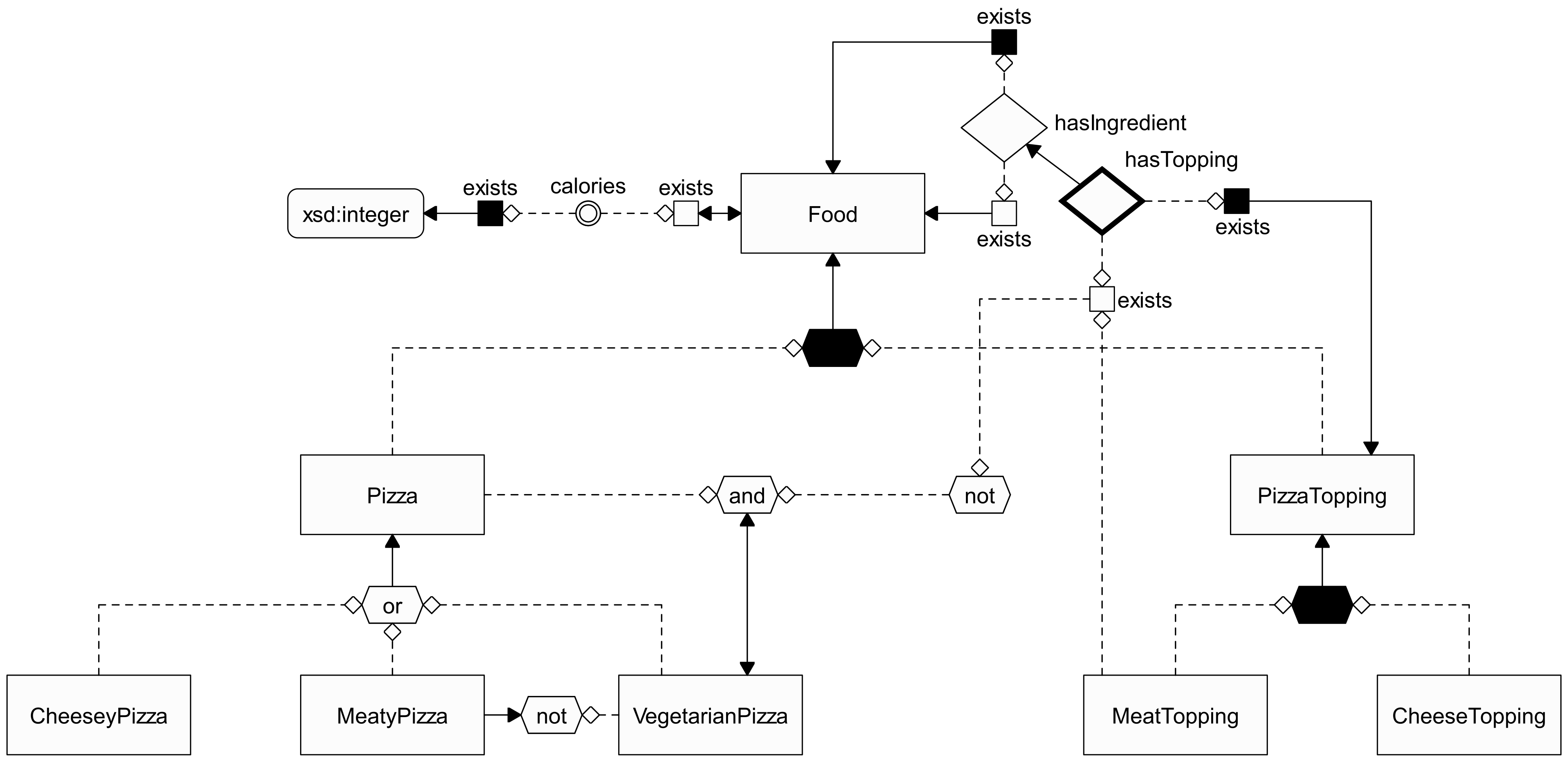
In
Figure 6, we provide the
Graphol specification of a portion of the Pizza ontology we have used in some previous examples. We also present below a logically equivalent representation of such ontology given in terms of DL assertions.
5. Comparison with UML Class Diagrams
In this section, we discuss more in depth the relation between
Graphol and UML class diagrams. This section is mainly addressed to people knowledgeable with UML and willing to approach ontology modeling. The aim here is to highlight the differences between the two formalisms, so that it can be easier to understand the potential of ontology design and the shift in the modeling tools that is required to move from conceptual models of limited expressiveness to full-fledged powerful ontology languages. The content of this section should also further help understanding the syntax of
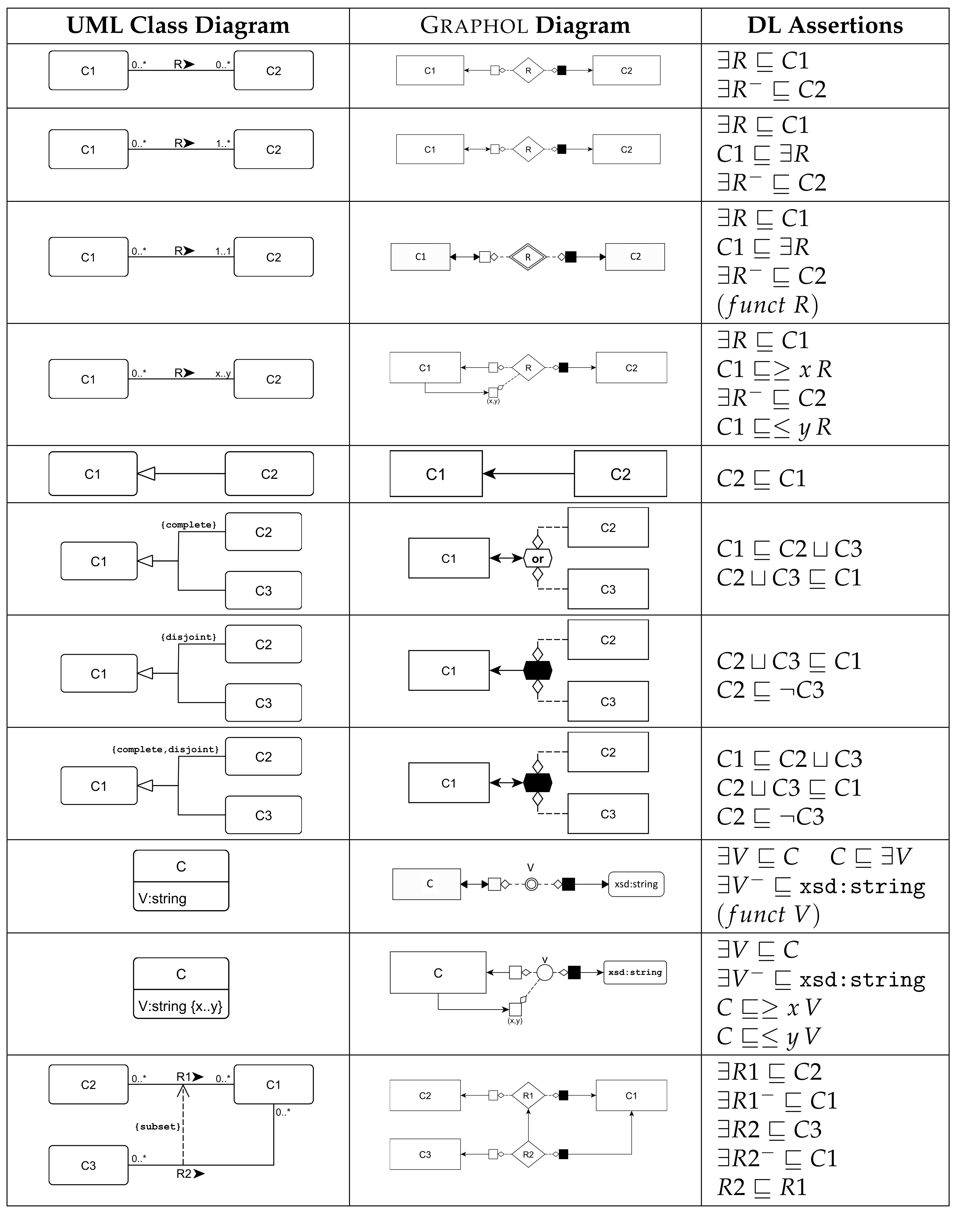
Graphol starting from that of UML class diagrams. In
Figure 7, we show how the main UML constructs are expressible in
Graphol and for each construct we specify the corresponding OWL 2 axioms, expressed in DL syntax (UML
n-ary relationships are not considered, since they are not directly expressible in OWL 2 and can always be captured using only roles, i.e., binary relationships, through reification, similarly for role attributes. We also note that all domain/range restriction nodes without labels in
Figure 7 have to be read as if they were labeled with “exists”, as said in
Section 4). In the first four rows of the figure we show how to represent in
Graphol a UML relationship R between two concepts, with different cardinality restrictions. In the first row, where there are no such restrictions, we simply type R by requiring that its domain belongs to concept C1 and its range to concept C2. This is performed through two
Graphol inclusion assertions, corresponding to the DL assertions
and
. In the second row, we add a mandatory participation of C1 to R (indicated in UML with a min cardinality restriction
). In
Graphol, this is reflected by adding an inclusion edge from the concept node C1 to the domain of the role node R. In the third row, the UML diagram specifies that the participation of C1 to R is both mandatory and functional (notice the cardinality restriction
). In
Graphol this can be easily specified by using the shortcut for global functionality introduced in
Section 4.3. Indeed, in UML both the domain and range of a role are always typed on a named concept, and thus every local cardinality restriction is actually global, in the sense that every object participating in the domain or range obeys it. In the next row, the participation of C1 to R is constrained by the cardinality restriction
. This is represented in
Graphol through the use of a second domain restriction node labeled with “
”, besides the one used to type the domain of R. The following four rows show the main cases of concept hierarchies. Here, through the union node (the hexagon labeled “or”), we represent the union expression between the two concepts C2 and C3, while we use the black hexagon (a shortcut introduced in
Section 4.3) to represent their disjoint union expression. Notice that completeness of a hierarchy is specified through a double-headed arrow. The next two rows describe how attributes and restrictions over them are depicted. Note that in
Graphol these are treated analogously as roles (we recall that in UML, in the absence of a cardinality restriction on attributes, they are considered mandatory and functional). Finally, in the last row, we have an example of role hierarchy, depicted in
Graphol as two role nodes linked by an inclusion edge.
6. User Evaluation Study
In this section, we present the results and setup of the user evaluation tests we carried out on the Graphol language. The goal of the tests was to evaluate the effectiveness of Graphol for ontology design and understanding. Both these aspects were tested independently and in comparison with other ontology languages similar, in spirit, to Graphol. Users with different backgrounds and levels of experience in ontology and conceptual modeling participated in the tests.
We conducted two different studies on different models and in which users were asked to perform a variety of editing tasks.
6.1. Setup of the Study
Before defining the definitive setup of the user study, we conducted two test runs with ontology and conceptual modeling experts who were already familiar with the Graphol language, which allowed us to iteratively improve the setup of the experiments. Our primary goals for these test runs were to verify that the tasks which we asked to perform were clear, and that their difficulty was adequate for the expertise of the final test participants. Examples of modifications that we made were the removal of overcomplicated tasks, the modification of several questions to avoid ambiguity in what the questions were asking, the refinement of the cheat sheets which were handed out with the questionnaires, and the definition of the time limits for each part of the experiments.
Because we conducted two different studies, with two groups of users and on different dates, we also took advantage of the experience of the first test to refine the second one. For instance, we made some modifications to the tutorial slides which were presented prior to the second test, in light of some doubts that were expressed by the users during the presentation of these slides during the first test.
6.2. Objectives of the Study
The design of our user evaluation study was geared towards the achievement of two main objectives.
Evaluate the difficulty of using the Graphol language for ontology comprehension and editing by users very experienced in conceptual modeling and (in some cases) with basic skills in logics and ontologies.
Evaluate the difficulty of approaching and learning the Graphol language for users with only basic knowledge of conceptual modeling and little or no experience with ontologies, both in isolation, and in comparison with another graphical ontology language that is heavily based on a formalism that is already familiar to them.
In accordance to these two objectives, we identified two groups of test participants, and defined two different types of tasks for each of these groups. Further details of the test participants, of the required tasks, and of the structure of the two tests are given in the remainder of this section. Here, we give a brief sketch of these two tests: the first one included a series of comprehension tasks and of editing tasks on two ontology models represented in the
Graphol language; the second one, involving users with limited knowledge of conceptual modeling and ontologies, instead included two sets of comprehension tasks on two ontologies represented in
Graphol and in OWLGrEd [
29,
49].
The reason for limiting the comparative evaluation of Graphol with OWLGrEd to the comprehension test with less-skilled users is that the purpose of the test was to verify that the Graphol language could be learned and used by these users with no more effort and difficulty than that needed for another language which is, by its very nature, more recognizable, due to its strong relation to UML class diagrams. Therefore, it was not in our interest to gauge the effectiveness of Graphol against OWLGrEd, or any other similar visual language, among more expert users. Instead, our test with these users was specifically designed towards measuring their perception of Graphol as a viable candidate for future use in the design of ontologies in real life.
Furthermore, we have not carried out a comparative evaluation of our language with ontology editors which do not provide solutions for graphic editing and which are based on formal non-graphic languages, such as Protégé, given that our main goal is to deal with users who are not necessarily experts in formal languages and ontologies.
6.3. Participants
Participants were recruited among computer science master’s and Ph.D. students, postdocs, and researchers. Eighteen participants took part in the test: ten with only basic knowledge of conceptual modeling and limited or no experience with ontologies (
beginners), and eight with advanced skills in conceptual modeling and basic knowledge of ontology design and logic (
experts).
Table 4 recaps some descriptive statistics about the age of the users, their education degree, the number of years of experience with ontologies, and their knowledge in ontologies and conceptual modeling. Note that, as expected, the knowledge of conceptual modeling among experts is in general very high (4.2 out of 5 average, with a low standard deviation of 0.7), and is fairly high among beginners (3.3 out of 5, again with a low standard deviation of 0.7). Furthermore, the average knowledge of ontologies is lower than that of conceptual modeling for both experts and beginners.
6.5. Language for Comparison
Among the available language candidates for the comparative test, we chose OWLGrEd [
49,
74] which allows for designing OWL 2 ontologies through a graphical notation based on UML class diagrams. OWLGrEd was chosen because its goal and its expressive power are akin to
Graphol’s, while its visual representation and UML-based design principles are rather different from those of
Graphol, but are accessible, at least without big efforts, to a user with knowledge in UML class diagrams. As stated earlier, among our goals was to evaluate the difficulty of approaching the
Graphol language for a non-expert user, in comparison to that of learning a language based on a formalism with which the user is familiar with, and OWLGrEd is an ideal fit for this task.
The comparative aspect of the study was limited to these two languages in order to avoid encumbering the users with an excessive amount of new information to process during the tests.
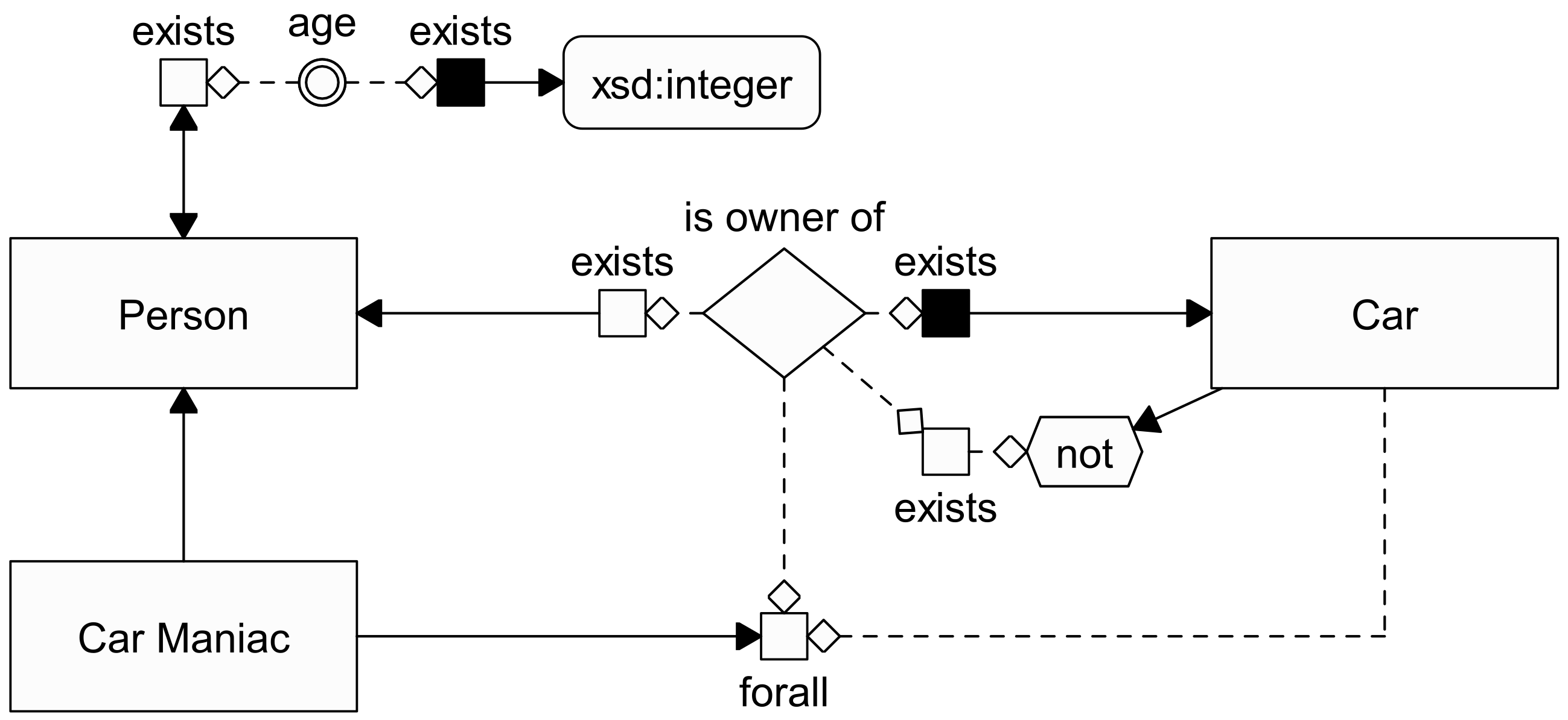
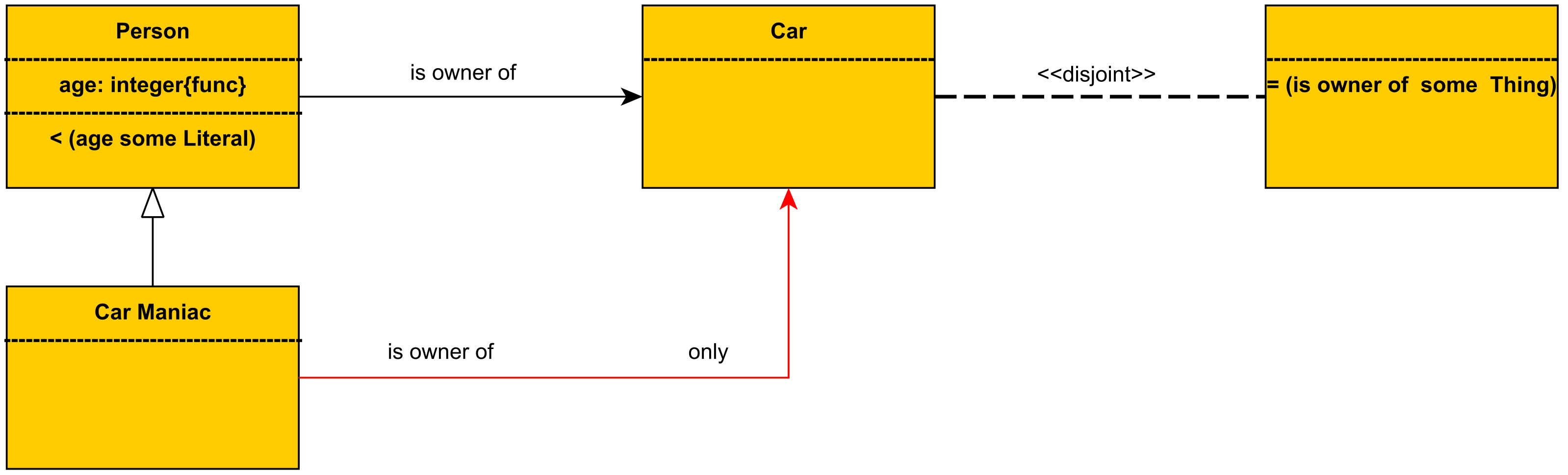
Here, we give some further details about OWLGrEd, and in
Figure 8 and
Figure 9, provide a very simple example of a model represented respectively in
Graphol and OWLGrEd. For a complete presentation of OWLGrEd, we refer the reader to [
29,
49,
74].
The OWLGrEd notation is based on UML class diagrams. Specifically,
- -
OWLGrEd concepts are represented as UML classes, without operations;
- -
OWLGrEd attributes are represented as UML class attributes, but with different default cardinalities;
- -
OWLGrEd roles are represented as UML binary associations with the arrow indicating the direction, from the domain to the range. OWLGrEd roles are thus typed in both the domain and the range;
- -
OWLGrEd cardinalities on roles are represented as UML cardinalities on roles, with the possibility of further refining the cardinality;
- -
OWLGrEd cardinality restrictions on attributes are represented as UML cardinalities on attributes;
- -
OWLGrEd inclusions between concepts are represented as UML ISAs between classes;
- -
OWLGrEd generalizations are represented as UML generalizations, using a special graphical symbol;
- -
OWLGrEd uses the OWL 2 Manchester syntax to specify expressions which denote complex concepts;
- -
OWLGrEd role restrictions are represented as red arrows from the concept which is included in the restriction to the concept that qualifies the restriction, labeled with the name of the restricted role.
6.6. Tasks
We designed a series of model comprehension tasks for both the Pizza and LUBM ontology models, and of model modification tasks for the Family ontology model. The tasks were designed to present a varying degree of difficulty to the user: those for beginners were limited to more basic aspects of conceptual modeling, while those presented to experts also focused on slightly more advanced aspects.
Each comprehension task consisted of answering a question regarding the domain represented by the given model. Question types vary, from open format questions to closed format (or multiple choice) questions, to yes or no questions. Each modification task instead requested the user to modify the given
Graphol model of the Family ontology by modeling one or more assertions, provided in natural language. The complete set of tests is provided in the
Supplemental Material.
For each task, the participant was asked to measure the time in minutes in which he completed the task. We also asked each participant to indicate, on a scale from 0 to 4, the clarity and the easiness of each task. To understand the difference between these two response variables, consider that the participant may think he has clearly understood what he must do for a certain task, but may not be able to easily place it into practice, or vice versa. In different words, the first variable is a measure of the quality of the questionnaire, while the second is of the tools the user is provided with to carry out the tasks. Examples of the two question types are provided below.
- -
Was the question clear?
Not clear at all Very clear
- -
Were you able to easily answer this question?
Not at all Absolutely
6.7. Structure of the Study
Here we provide the details for the evaluation studies of beginners and experts, which were conducted separately, on different dates.
Beginners:
Introduction and briefGrapholtutorial (15 min): a general introduction to the purpose of the experiment, and a brief tutorial on ontologies and on the Graphol language.
Brief OWLGrEd tutorial (15 min): a brief tutorial on the OWLGrEd language.
Brief user background questionnaire (5 min): participants had to answer a brief questionnaire in which they were asked to provide some personal background information, as well as to rate their knowledge of conceptual modeling and ontologies on a scale from 1 to 5 (with 1 indicating extremely low and 5 extremely high expertise), to indicate how many years they had of experience with ontologies (if any), whether they were familiar with some of the more popular ontology editors and knowledge representation and conceptual modeling formalisms, and whether they had any experience with ontologies in real-life scenarios or in manually creating or editing ontologies.
LUBM comprehension tasks (40 min): each user was asked to answer ten questions on the LUBM model they were provided. Half of the users were provided a Graphol version of the LUBM model, and half an OWLGrEd version.
Pizza comprehension tasks (40 min): each user was asked to answer ten questions on the Pizza model they were provided. Half of the users (those which were provided the OWLGrEd version of the LUBM model) were provided a Graphol version of the Pizza model, and half an OWLGrEd version.
Ex-post survey (10 min): after all the comprehension tasks were completed, we asked the participants to compile a short survey regarding their experience. The survey required the users to rate, on a scale from 0 to 4, the general difficulty of the comprehension tasks, the difficulty of learning the Graphol and OWLGrEd symbols, the difficulty of using Graphol and OWLGrEd to read ontologies, and, optionally, to indicate aspects of Graphol and OWLGrEd which they particularly liked, or that they would like to see improved.
Experts:
Introduction and briefGrapholtutorial (30 min): participants were given the same introductory tutorial on ontologies and on the Graphol language as the beginners, with the addition of some more complex features on the Graphol language which were featured in the expert questionnaire but not the beginner questionnaire.
Brief user background questionnaire (5 min): we asked the participants to fill out the same background questionnaire given to the beginners.
Grapholcomprehension tasks (35 min): after completing the introductory part on Graphol, each user was asked to answer ten questions on the Graphol model of the Pizza ontology they were provided.
Grapholediting tasks (35 min): we asked each participant to perform ten editing tasks on the Graphol model of the Family ontology they were provided.
Ex-post survey (5 min): after carrying out both the comprehension and editing tasks, the users were asked to fill out a brief survey, analogous to the one given to the beginners.
We now discuss some more detailed aspects of the study.
- -
All participants, in support of their tasks, were provided with documentation regarding the languages in play for that specific task. Specifically, the questionnaire included some cheat sheets which recapped the symbols of the Graphol and the OWLGrEd language (the latter only for tests carried out by beginners) and their meaning, along with some examples of the representation of some of the most common ontology expressions and assertions in the two formalisms. Additionally, users were provided with a printout of the slides of the introductory tutorials.
- -
The order in which the tasks were presented in the questionnaires was intentionally random, i.e., not linked to the expected difficulty of each task. This choice was made in order to compensate for a potential bias given by the learning curve of familiarizing with Graphol or OWLGrEd during the course of the tasks. In other words, we wanted to avoid facilitating the participants by allowing them to face easier questions at the beginning of each task, and more difficult ones at the end, when they would probably have gained familiarity with the language.
- -
The experimental design method we chose for the comparative study between
Graphol and OWLGrEd is the
within-subjects method, common in HCI [
75]. This choice, as opposed to the between-subjects technique, was made mainly due to the limited number of participants to the experiment. Therefore, each user was asked to complete the comprehension tasks both for the
Graphol language and for the OWLGrEd language. In order to avoid the transfer of learning effects between tasks, we split the ten users into two groups of five, and asked the first group to first carry out the comprehension tasks on the
Graphol version of the LUBM model, and then the comprehension tasks on the OWLGrEd version of the Pizza model, and the second group to do the opposite.
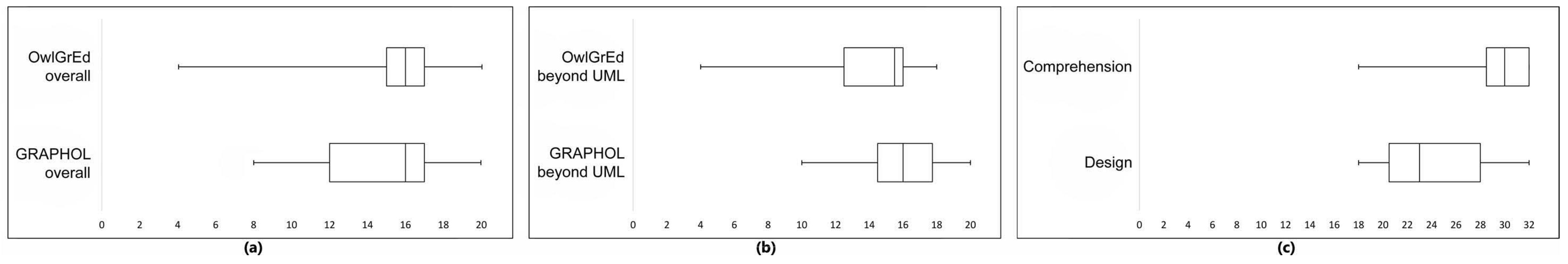
6.8. Study Results
Figure 10 summarizes some of the results of the tests. Each box plot shows the full range of variation, from minimum to maximum, indicated by the whiskers, the likely range of variation, indicated by the two boxes, and the median value. The overall correctness results for the comparative test, shown in boxplot (a), indicate a good comprehension level by the novice users of the
Graphol language, that can be considered comparable to the one obtained for OWLGrEd, which is based on UML class diagram, which is a formalism which the users were familiar with. Boxplot (b) summarizes the correctness results of the comparative test limited to five questions that deal with complex modeling aspects that go beyond UML, i.e., questions 1, 3, 5, 9, and 10 on the LUBM questionnaires, and questions 2, 4, 5, 7, and 9 on the Pizza questionnaires. These results confirm that users were able to more easily understand the completely graphical representation provided by
Graphol than the formulas or non-UML constructs adopted in OWLGrEd. Finally, boxplot (c) shows the correctness results of the non-comparative test by the more expert users. The very high scores indicate that such users quickly learned how to read
Graphol diagrams and how to use the language for modeling.
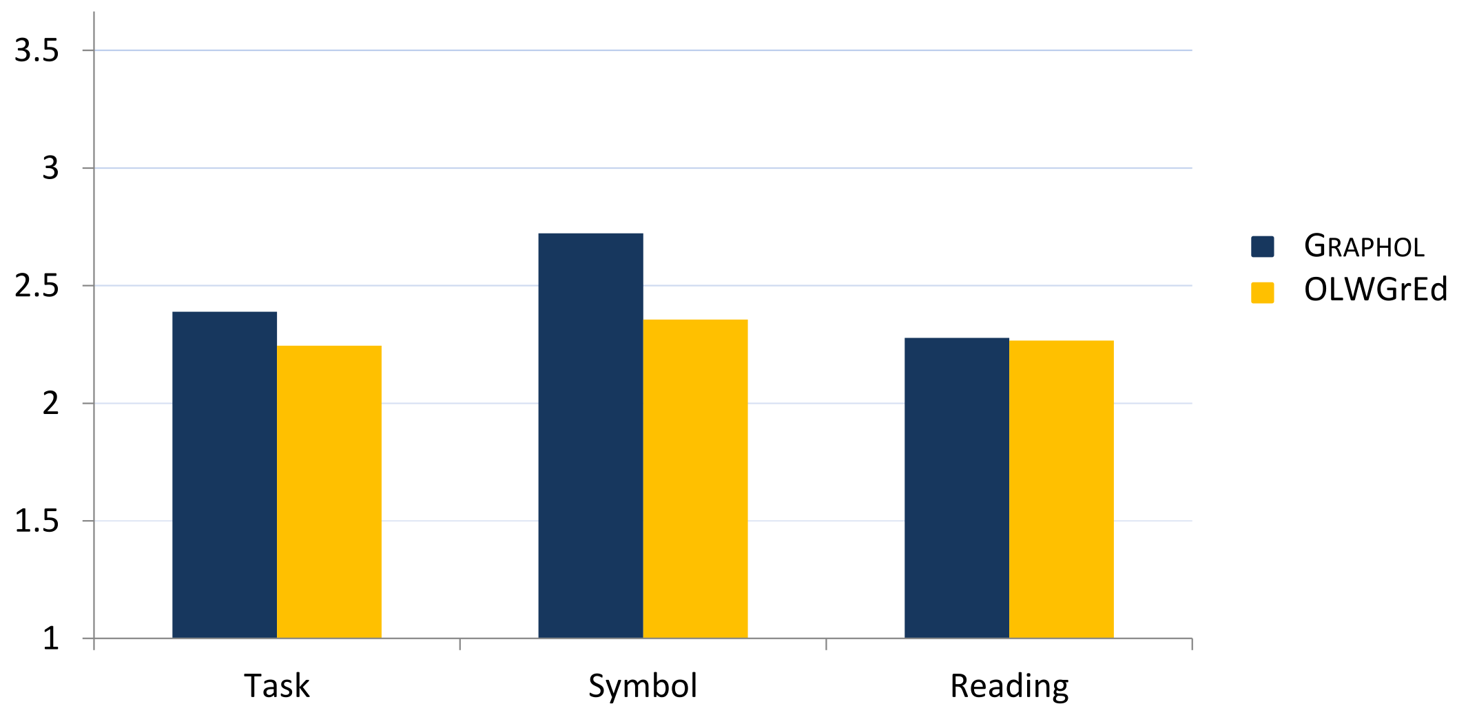
6.9. Post-Questionnaire Analysis
Finally, we discuss the results of the post-test questionnaires, which were presented to all participants. We recall that the goal of the post-test questionnaires was to measure the perceived general difficulty of the tasks required, of learning of test language symbols and of using
Graphol to read ontologies. The average results of the questionnaires are shown in
Figure 11.
As one can see, the feedback essentially confirms the positive impression gained from the analysis of the test results. Users felt about as comfortable reading ontologies modeled through the novel Graphol language as they were with those in OWLGrEd (almost identical average scores for “Reading Difficulty”), even though, as expected, they felt that learning Graphol’s symbols was slightly more difficult than learning OWLGrEd’s UML-based ones (“Symbol Difficulty” scores). Indeed, we recall that the participants were knowledgeable in conceptual modeling languages such as UML class diagrams and entity–relationship diagrams (ER). While OWLGrEd strictly adheres to the former (at the cost of recurring to expressions in logical languages when needed), Graphol is rooted in ER, but it adds several graphical elements in order to completely cover OWL 2 without using non-graphical formulas.
The average values in the “Task Difficulty” column are more a reflection of the difficulty of the tests rather than the languages, but in both cases users seem to feel that the tests were not excessively difficult (average difficulty score of 2.4 and 2.2 out of a maximum of 5).
We finally point out that the results of the tests brought to light the need to enhance the usability of the language through a dedicated ontology tool. We used many suggestions we collected during the evaluation study to push forward the development of the Eddy editor tool for
Graphol [
23], which is also equipped with some specific functionalities to facilitate the specification of
Graphol ontologies (e.g., through commands for the automatic construction of some recurrent modeling patterns, such as concept hierarchies or role typing axioms).
7. Conclusions
In this article, we studied the graphical language for ontologies Graphol, which is as expressive as OWL 2. As we have illustrated, the key features of Graphol are its precise semantics, its expressive power, and its completely graphical representation of ontologies, inspired by popular conceptual modeling languages, such as ER. This combination sets Graphol apart from other proposals.
We remark, once again, that an editor, called Eddy [
22], specifically tailored to support the specification of
Graphol ontologies, is available. This tool provides advanced functionalities for drawing syntactically correct
Graphol diagrams, for documenting them, and for translating them into standard OWL 2 syntax. Eddy is currently developed by ODBA Systems (
http://obdasystems.com/, accessed on 17 January 2022), a Sapienza startup company, and is available as open-source software (
https://github.com/obdasystems/eddy, accessed on 17 January 2022).
Currently, our work is mainly focused on devising
Graphol-like mechanisms for the visual specification of SPARQL queries over OWL 2 ontologies. Our idea is to automatically produce a query in SPARQL syntax on the basis of the selections of predicates performed by a user on a
Graphol ontology, which naturally allows to trace the basic graph pattern of the query, plus additional conditions imposed on the query variables through user-friendly visual mechanisms [
76].
We are also working to add additional features to the language itself, to allow an even broader scope of modeling possibilities. In particular, we are looking into the addition of metamodeling features such as metaconcepts, which are concepts whose instances can be concepts themselves, and metaproperties, which are relationships between metaconcepts. Metaconcept representation could be useful, for instance, for the representation in Graphol of formal ontologies, where specific metaproperties, such as, for instance, rigidity, can be exploited for expressing key aspects of the intended meaning of predicates in ontologies.


