Abstract
With the widespread deployment of 5G gaining pace, there is increasing interest in deploying this technology beyond traditional Mobile Network Operators (MNO) into private and community scenarios. These deployments leverage the flexibility of 5G itself to support private networks that sit alongside or even on top of existing public 5G. By utilizing a range of virtualisation and slicing techniques in the 5G Core (5GC) and heterogeneous Radio Access Networks (RAN) at the edge, a wide variety of use cases can be supported by 5G. However, these non-typical deployments may experience different performance characteristics as they adapt to their specific scenario. In this paper we present the results of our work to model and predict the performance of millimeter wave (mmWave) backhaul links that were deployed as part of the Liverpool 5G network. Based on the properties of the 802.11ad protocol and the physical characteristics of the environment, we simulate how each link will perform with different signal-to-noise ratio (SNR) and Packet Error Rate (PER) values and verify them against real-world deployed links. Our results show good convergence between simulated and real results and provide a solid foundation for further network planning and optimization.
1. Introduction
The ongoing deployment of 5G networks marks the start of next evolution wireless networking as technologies converge and use cases extend beyond traditional home/business use. This has implications for a range of environments, from dense urban deployments right through to sparse rural usage. Such deployments will necessitate end-to-end and top-to-bottom flexibility in terms of the mix of Radio Access Network (RAN) technologies used and how traditional back-ends are deployed (or not). In particular, 5G deployments are now being considered by providers beyond traditional Mobile Network Operators (MNOs) to provide connectivity and services for a wide range of uses. These include private 5G for use in Industrial Internet of Things (IIoT) and Industry 4.0 use cases, and community-based efforts such as those delivered by Liverpool 5G.
Due to this growth, ‘backhauling’ has become a central challenge for operators in order to provide multi-gigabit capacity while using cost efficient technologies [1]. Backhaul solutions can be categorized as wired (leased lines or copper/fibre) or wireless (point-to-point, point-to-multipoint over high-capacity radio links). Wired solutions are typically an expensive solution but offer unlimited bandwidth and ease of maintenance [1]. On the other hand, wireless solutions have the advantage of rapid and easy deployment at relatively low cost. In mobile networks, backhauling is expected to be filled by the 5G NR FR1 and FR2 standards but may be limited to licensed operators and incur significant costs and overheads. Therefore, millimetre wave (mmWave) techniques ranging from 30 to 300 GHz have become a feasible alternative, with larger bandwidth and unprecedented peak data rates [2]. Examples of mmWave technologies include the V-band (60 GHz) and E-band (70/80 GHz), and backhaul links using these bands may be well suited to supporting 5G due to their 10 to 25 Gbps throughput and low latency.
This paper provides a solution that models the configuration and performance for a 60 GHz mmWave 5G backhaul mesh network based on IEEE 802.11ad. The network is deployed as a service in the Liverpool 5G project to support the development of novel eHealth use cases and applications. More specifically, the paper discusses the viability of IEEE 802.11ad point-to-point links as a backhaul network in urban deployments. Our experiments largely validate the expected link performance based on the simulation parameters of distance, coding scheme and link quality but show that significant variability is introduced as a result of the real-world deployment. As such, some links match or even exceed the simulated performance, while others under-perform. These results will provide important feedback for other 5G deployments based on 60 GHz technology.
The remainder of the paper is structured as follows. First, a discussion related to work on private 5G deployments is provided in Section 2, and this is followed by a detailed description of the 5G topology deployed in the Liverpool 5G network. In Section 3, technical background related to the particular problems studied in this work are discussed, which includes a brief description of mmWave systems, modulation and coding schemes and link adaption, along with the general metrics to evaluate link performance. Following this, the process on how the scenarios have been modelled and implemented in MATLAB, including the simulation assumptions, link parameters and traffic model are discussed in Section 4. In Section 5, the simulation results showing the performance and efficiency of the 5G backhaul network are presented and discussed. Finally, Section 6 concludes this work.
2. Private and Community 5G Networks
2.1. 5G Non-Public Networks and Urban Deployments
The use of 5G technologies to support deployments beyond traditional MNO networks opens a wide range of applications and scenarios for wireless technologies. One area that has seen massive interest to date is in support of IoT-based deployments and particularly around Industry 4.0. The next generation of industrial services, from manufacturing to logistics, are being designed to heavily incorporate data networks to support a wide variety of sensor and communication requirements, where traditional wired technologies are either too expensive or infeasible to deploy on this scale. For example, even in a moderately sized factory site of 1–2 km2, the sheer scale of connectivity requirements would introduce significant problems, notwithstanding the need for flexibility in the case of reconfigurations and the potential to deploy this in a challenging or hazardous environment. As such, the use of 5G wireless technologies in this space provides many advantages including reduced cost and complexity while still providing good bandwidth and responsiveness. In the 3GPP scope, these are called private networks or non-public networks (NPNs) [3] as opposed to the traditional Public Land Mobile Networks (PLMNs).
These NPN 5G deployments could make use of a combination of shared and private base stations and backend infrastructure through slicing to provide network capacity solely provisioned for the use case. This area is still under active research in academia and beyond but an overview of some potential solutions are described here to provide context for our work. In order to support 5G NPNs, various scenarios have been envisioned whereby the 5G Core (5GC) can be provisioned and controlled locally or remotely, or through some combination of the above [4]. Essentially, both the Control Plane (CP), which provides device and network control such as access control and management, session management, mobility management and policy management, and the User Plane Functions (UPF), which deal with data routing and forwarding, need to be provisioned for the user in order to provide a 5G service [5]. On the one hand, an operator might choose to deploy just the gNB locally (or virtually through slicing) to save CAPEX and OPEX overheads and handle most of the backend functionality remotely, which greatly simplifies operation at the potential cost of some performance overheads. Conversely, a full local deployment would certainly be more expensive and complex to operate but would be solely provisioned and therefore more performant [6].
Moreover, the heterogeneous nature of available RAN technologies in 5G provides a powerful mechanism to support a range of devices and applications, from LoRa sensor devices, through to 4K streaming or VR-type users. In addition to 5GNR, an operator might make use of some version of LTE in addition to Wi-Fi, mmWave and other technologies to provide appropriate coverage [7]. Through splitting the RAN into a Central Unit (CU) and multiple Distributed Units (DUs), different levels of control can be applied. These functional splits dictate where in the stack the separation between the CU and DUs occurs and potentially offer a great deal of flexibility in terms of how sessions are managed in the RAN, from a very ‘low’ traditional split up to more innovative but complex ‘high’ splits [8].
Another interesting deployment area for 5G is in public networks deployed by and for a community [7]. Such networks can, for example, be setup by a local government or organization and provided to members where MNO coverage is not available or suitable or focused around a specific use case that meets a public need. In this case, there is again a wide range of potential deployment models that could be adopted depending on the specific circumstances. An organization might apply for a specific portion of the available spectrum in their area to deploy their own base stations, or adopt another unlicensed solution. For example, a town/city with available fiber infrastructure (perhaps to support a CCTV platform) could simply look to extend that into the necessary areas by using a Wi-Fi mesh or use more specialized and higher capacity technologies as needed. It is in this context that we introduce the Liverpool 5G network, which has been deployed as part of the DCMS 5G Testbeds and Trials Programme [9].
2.2. Overview of the Liverpool 5G Network
The infrastructure deployed in the Liverpool 5G project is illustrated in Figure 1. In the first phase of the project (from 2018 to 2020), the network topology consisted of 34 nodes and three gateways (POPs) installed in the Kensington area of the city. Each node in the backhaul mesh was collocated with a Wi-Fi AP to provide WLAN connectivity, with some nodes also supporting ZigBee low-power ad hoc networking. The network was designed in such a way that there was a line of sight link along any of the roads between deployed nodes and the connection was based on a mmWave link (IEEE 802.11ad). The nodes are Blu-Wireless DN-101LC stations and are attached to street lights or other street furniture at a consistent elevation. The nodes have 90 degree azimuth coverage, one independent beam and a maximum capacity of 5Gbps (Mac layer). The POP nodes are connected to the gateway through a fiber link, and backhauling is then handled via a local cloud service provider. Furthermore, due to the widely deployed nodes and the high path and penetration loss at 60 GHz, some links may require relays (multi-hop transmissions) to accomplish backhauling, and nodes are clustered around the nearest POP. In the current version of the network (2020–2022), this deployment has been extended to cover a wider area and provide more ubiquitous coverage. Each node is also collocated with a 5G small cell that will run in the N77 band and standalone mode. As such, any user with a compatible handset should receive connectivity within the Kensington area of Liverpool.
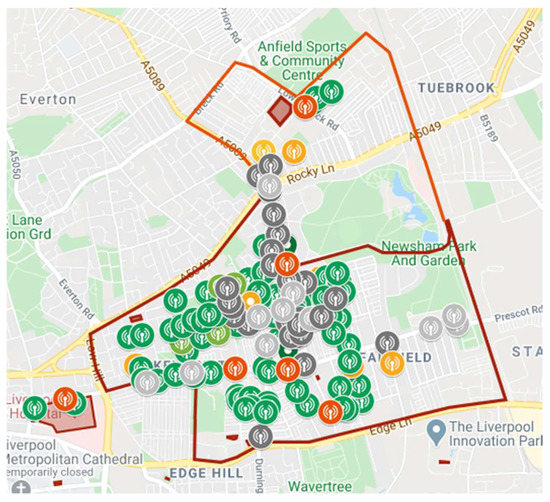
Figure 1.
Overview of Liverpool 5G Backhaul Deployment.
The aim of this deployment is to support a range of social and healthcare applications for the community, from simple health sensor and monitoring services through to VoIP, full HD or 4 K streaming for remote consultations and (potentially) low latency VR tools. As such, the network must be able to meet a challenging set of requirements. Of course, it is very difficult to guarantee a high rate of transmission (or a small latency) in conjunction with highly reliable packet delivery (small packet error rate), due to the random transmission errors caused by the unpredictable behaviour of this type of wireless channel. Specifically, when the link qualities in the network are poor, packets may be retransmitted several times across hops in order to reach their destination. This could result in aggregation and queueing of packets at the core relay nodes, which translates to unreasonably large average end-to-end delay, as well as a low rate of transmission. However, in order to determine the optimal operating point and achievable Quality of Service offered by the network, it is important to analyse the trade-off between the throughput, latency and reliability (PER and PDF) to improve the overall network performance [10]. Finally, average latency, which is defined as the average time from when the packet transmission starts at the source station to when the packet is correctly received by the destination [11], is a particular issue for applications which have strict real-time requirements such as video conferencing or VoIP calls. The next section takes a more detailed look at the characteristics of communications at 60 Ghz to provide a foundation for our analysis work.
3. Communication in the 60 Ghz Band
The use of the 60 GHz frequency for wireless communication goes back to 2001 when the US regulator (FCC) adopted rules for unlicensed operations in the 57 to 64 GHz band for commercial and public use. Radios operating in the 60 GHz band have some unique characteristics that make them different to radios operating in the traditional 2.4/5 GHz bands. Using 60 Ghz leads to smaller sizes of RF components, enabling a more compact realization of an array structure, which in turn offers larger antenna gain with high directivity. Furthermore, oxygen absorption attenuates 60 GHz signals such that they cannot travel far beyond their intended path. These properties can also help reduce interference among terminals, enhance data security and, very importantly, enable the spectrum to be re-used in dense deployment scenarios. The 60 GHz band also allows very high data rate communication in applications such as video conferencing, media streaming and gaming.
Zhen Gao et al. in [12] stated that mmWave is suitable for backhaul links in ultra-dense wireless networks due to several unique properties: having a high capacity, being inexpensive and small form factor equipment, and having an immunity to interference. More recently, research has been conducted on the use of this technology to support densely meshed wireless backhauls as shown in Figure 2. The work in [13] studied the performance of a mmWave meshed backhaul deployment in a district of Barcelona. The links between nodes in the network were based on IEEE 802.11ad technology at 60 GHz. The work demonstrated the viability of the technology over multiple hops and showed the influence the number of gateways (POPs) and the number of radio channels available has on performance.
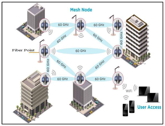
Figure 2.
Example of wireless backhaul network.
Further work in [14] addresses the challenges and the properties of mmWave communications for 5G to support the re-design of protocols and architectures; specifically, interference management and spatial re-use. For a high-level view of 5G fronthaul and backhaul wireless transport over mmWave the reader is referred to [15]. To further promote the development of mmWave communications, many other projects are currently evaluating this technology in the UK including the Liverpool 5G Testbed [16], the 5G Smart Tourism project [17] and the Worcestershire 5G Consortium Overview project [18], to name only three.
IEEE 802.11ad, also known as WiGig, is an enhancement to the 802.11 standard that enables multi-gigabit wireless communication in the 60 GHz unlicensed band [19]. The current IEEE 802.11ac standard can support a maximum of 2.5 Gbps with three 160 MHz channels and 256-QAM data rate. In contrast, the 60 GHz band could provide a maximum throughput of up to 7 Gbps. However, utilizing this spectrum resource comes with challenging propagation characteristics such as strong attenuation from obstacles and huge path loss. Furthermore, due to severe penetration loss and reflection due to the short wavelength, mmWave communications are generally only feasible in line of sight (LoS) environments. To overcome these drawbacks, IEEE 802.11ad provides a robust modulation and coding scheme and link adaptation mechanism to optimize throughput and minimize packet and bit error rate. In addition, the standard defines a directional communication scheme that takes advantage of beamforming antenna gain to cope with the increased attenuation in the 60 GHz band [20].
3.1. Modulation and Coding Scheme
The modulation and coding scheme (MCS) index value summarizes the modulation type (e.g., BPSK, QPSK, 16QAM) and the coding rate that is used in a given physical resource block (PRB). Typically, a higher MCS index offers a higher spectral efficiency (which translates to a higher potential data rate) but requires a higher SNR to support it. Depending on the link quality metrics (LQMs) a node will dynamically choose an appropriate MCS in order to provide the best possible performance.
In the 802.11ad specification, three different PHY modes are defined based on how they can be used. The Control PHY (MCS0) is designed for low SNR operation with low throughput communication (27.5 Mbps) and is mainly used during the beamforming training (BF) phase. The Single Carrier (SC) PHY enables a power efficient and low complexity transceiver implementation. It provides a good trade-off between average throughput and energy efficiency. SC-PHY defines MCS 1–12, of which MCS 1–4 are mandatory modes to be implemented in all devices for interoperability [21]. MCS 13–24 provides the maximum 802.11ad data rates up to 6.76 Gbps and adopts orthogonal frequency-division multiplexing (OFDM) technology, which is very efficient in multipath environments [21]. However, its implementation is complex and therefore targets devices with less stringent power and design constraints. Finally, the DMG low-power SC-PHY with MCS 25-31 is an optional SC mode that can provide lower processing power by using Reed–Solomon instead of low-density parity check (LDPC) codes [22,23].
In this work we consider the SC-PHY model, which ranges in value from MCS 1 to MCS 12. Table 1 below lists the MCS values defined in the IEEE 802.11ad standard and gives their corresponding modulation schemes, coding and data rates. In the SC-PHY model, the lowest SC data rate is 385 Mb/s (MCS 1), which is implemented using BPSK modulation and rate 1/2 code with a symbol repetition of two. MCS 1–5 are all based on pi/2-BPSK modulation. MCS 2, 3, 4 and 5 use code rate 1/2, 5/8, 3/4 and 13/16, respectively. MCS 6–9 are based on pi/2-QPSK modulation, whereas MCS 10–12 are based on pi/2-QPSK [23].

Table 1.
SC_PHY Modulation and Coding Schemes.
3.2. Link Adaptation
In wireless communication systems, the quality of a wireless signal received by nodes depends on a number of factors: the distance between the nodes, path loss exponent, log-normal shadowing, short term (Rayleigh) fading and noise. In order to improve system capacity and peak data rate, the signal transmitted to and by a particular node is modified to account for the signal quality variation through a process commonly referred to as link adaptation. This is also known as adaptive modulation and coding (AMC) techniques [24].
In communication systems, the use of AMC techniques allows the system to achieve higher spectral efficiency by dynamically changing the modulation and coding schemes based on the channel statistics so as to improve overall spectral efficiency. In other words, it is utilized to set the modulation and coding in order to reflect the features of the wireless link and to maximize throughput. Moreover, AMC has been widely used to match transmission parameters to time-varying channel conditions in order to enhance the spectral efficiency while adhering to a target error performance over wireless channels [25,26].
A number of research works have been conducted on link adaptation, and new link adaptation schemes have been proposed. Holland et al. [27] introduced a Receiver-Based Auto-Rate (RBAR) protocol based on the Request-To-Send (RTS) and Clear-To-Send (CTS) mechanism by adjusting the IEEE 802.11 standard. The basic idea of RBAR is that the receiver estimates the wireless channel quality using a sample of the instantaneously received signal strength at the end of the RTS reception, then selects the appropriate transmission rate based on this estimate, which feeds back to the transmitter, and finally the transmitter responds to the receipt of the CTS by transmitting the data packet at the rate chosen by the receiver [28]. Kamerman et al. [29] presented the Auto Rate Fall-back (ARF) protocol for IEEE 802.11, which is used in Lucent’s WaveLAN devices. With ARF, the sender selects the best rate based on information retrieved from previous data packet transmissions and incrementally increases or decreases the rate after a number of consecutive successes or losses.
3.3. Beamforming
Beamforming refers to a technique that dynamically shapes the beam pattern to focus on specific directions. It is a spatial filtering technique used in smart antennas and the main objective is to maximize the received power directed towards a certain node while minimizing the interference power towards undesired nodes [30]. A signal processor controls the excitation of antenna array elements to synthesize a desired radiation pattern [31]. In other words, beamforming works by combining elements in a phased array in such a way that signals at particular angles experience constructive interference (at the main lobe), while others experience destructive interference (at the nulls) and at the receiver by having gains in one direction and attenuation in others.
The beamforming technique is used in smart antennas for transmitting and receiving signals in massive multiple-input multiple-output (MIMO) systems. MIMO systems combined with beamforming antenna array technologies are expected to play a key role in 5G wireless communication systems [30]. Apart from a higher directive gain, these antennas offer complex beamforming capabilities that increase the capacity of networks by improving the signal-to-interference ratio (SIR).
Beamforming is mandatory in 802.11ad, and both transmitter-side and receiver-side beamforming is supported. In the 802.11ad standard, beamforming training determines the appropriate receive and transmit antenna sectors for a pair of nodes. The beamforming is split into two phases. The sector level sweep (SLS) and beam refinement phase (BRP). During SLS, an initial coarse-grained antenna sector configuration is determined. Thus, in the SLS phase each of the two nodes either trains or receives the appropriate transmit antenna sector. This information is used in a subsequent optional BRP to fine-tune the selected sectors [20]. During this stage, antenna weight vectors that vary from predefined sector patterns are evaluated to further optimize transmissions on phased antenna arrays.
3.4. Performance Evaluation
As part of the deployment and operation of the 5G network, an evaluation of the mmWave link performance was undertaken to better understand the characteristics of 802.11ad when it is deployed in this manner. The outcomes of this work will then be used to optimize the clustering and link level configuration of the network going forward. Ultimately, our goal is to develop dynamic optimization algorithms that could be used as part of a self-optimizing network (SON) managed by Software-Defined Wireless Networking (SDWN). This algorithm could use information on link characteristics from across the meshed backhaul, along with current monitoring statistics on traffic load, to reconfigure links and optimize routing to perform load balancing and help enforce user QoS.
To date we have undertaken preliminary work to evaluate the optimal clustering and channel selection based on simple Dijkstra shortest path routing algorithms and calculated the optimal link distance based on the expected 802.11ad performance using packet error rate in a typical ‘street canyon’ deployment such as an urban environment. This means that we are now in a position to predict link performance for a given deployment and alignment of nodes. Our aim for the work presented in this paper was, therefore, to model a real node deployment as part of the latest phase of the project, which began in September 2021, and then verify our predicted performance using monitoring information once it was operational. The modelled deployment will be explained in detail in the next section.
4. Simulation Model
We consider a case study to simulate the deployment of the backhaul network on Sheil Road in Liverpool, by the Fairfield Medical Centre. This deployment was developed based on a 5G network planning tool, which provides an online copy of Kensington in Liverpool, for the Liverpool 5G network (https://www.cgasimulation.com/network-planning-tool/, last accessed: 15 December 2021). From this tool, we were able to build a simulated deployment of nodes and model their performance in an urban environment [32]. Figure 3 illustrates the Fairfield Medical Centre modelled by the planning tool. Moreover, the tool provides information for each of the nodes in the network, such as the site of the node, the kind of installation, the direction, the latitude and the longitude, which we used to build our simulation.
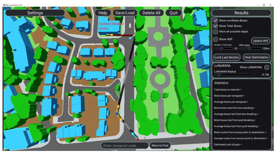
Figure 3.
Copy of the Fairfield Medical Centre deployment.
Using these sites, we were able to obtain details on the link distances and orientations to build a MATLAB-based simulation of this end-to-end deployment that allowed us to carry out the performance evaluation illustrated in the next section. These sites are simulated based on IEEE 802.11ad, which defines a directional multi-gigabit (DMG) transmission format operating in the unlicensed band around 60 GHz, using single carrier (SC) PHY link [32]. The channels, on the other hand, are modelled as a multipath fading channel using the model environment of ‘street canyon hotspot’ [33].
We evaluated the individual link performances in terms of their Packet Error Rate (PER) as a function of the signal-to-noise ratio and for different modulation and coding scheme values. Specifically, first, a set of SNR points in dB were selected based on each simulated MCS. Second, for each SNR point, multiple packets were transmitted through a TGay millimeter wave channel [34], then synchronized and demodulated, and the received Physical Layer Convergence Procedure Service Data Units (PSDUs) were recovered. Third, the received PSDUs were compared to those transmitted to determine the number of packet errors and hence the PER. The number of packets considered to compute the PER for each SNR point depends on the following parameters: (1) the maximum number of packet errors simulated at each SNR point. When the packet error number reaches this limit, the simulation at this SNR point is finalized; (2) the maximum number of packets simulated at each SNR point, which limits the length of the simulation if the packet error limit is not reached. In order to obtain meaningful results, we considered 100 and 1000 as the maximum number of packet errors and maximum number of packets, respectively [34].
5. Simulation Results
5.1. Evaluation in MATLAB
To evaluate the link performance of the Sheil Road deployment, we first simulate the network layout using MATLAB as shown in Figure 4, based on the information identified in the previous section. The MATLAB simulator is built to accurately model the properties and parameters of IEEE 802.11ad networks and closely represents the deployment in Liverpool 5G Create in terms of node position and alignment. Specifically, in Figure 4 there are three links used to connect three IEEE 802.11ad access points (APs), i.e., nodes 2–4, with node 1 acting as a gateway according to the 5G Create deployment illustrated in Figure 3. Moreover, links that are configured to work on the same channel have the same colour in the figure, i.e., red for Channel 2 at 60.48 GHz and blue for Channel 3 at 62.64 GHz. Table 2 summarizes the main simulation parameters [32,33,34].
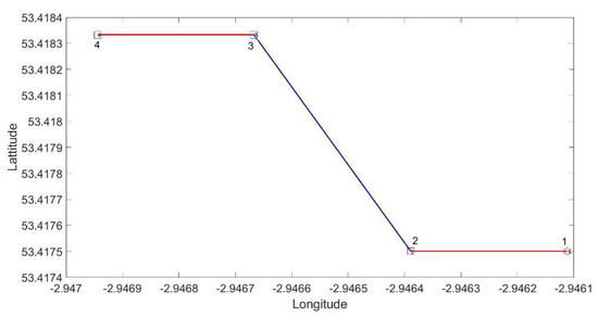
Figure 4.
Network Layout.
Table 2.
Simulation Parameters [32,33,34].
We next present the performance of the longest link, i.e., Link 2 from node 2 to node 3 in Figure 4, which is 94.4 m long, and one of the shortest links, i.e., Link 3 from node 3 to node 4, which is 18.35 m long. As introduced in the previous section, the PER of these links was computed as a function of the SNR and for different MCS values as shown in Figure 5 for Link 2 and Figure 6 for Link 3, respectively. As can be noted in both figures, the PER represented in log scale decreases as the SNR value increases for all MCS types. In addition, higher MCS can be achieved for a targeted level of PER when the SNR of the considered link increases. For instance, in the case of very low targeted levels of PER, in Link 2 MCS 11 can be achieved when the PER in percentage is 1.3% and the SNR is 20dB, while MCSs 8 and 9 can be considered in the case of targeting a PER of 1% and 0.2%, and SNR of 14 dB and 15 dB, respectively. In Link 3, in the case of low targeted levels of PER, MCSs 11, 8 and 9 can be achieved when the PERs are 2.5%, 0.8% and 0.57%, and the SNRs are 21dB, 16 dB and 18.5 dB, respectively.
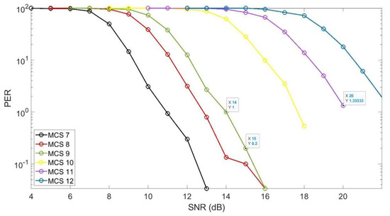
Figure 5.
Link2 performance.
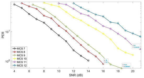
Figure 6.
Link3 performance.
5.2. Validation through GRAFANA
In order to validate the link performance of the Sheil Road deployment illustrated above, we monitored Link 2 and Link 3 through a Grafana-based interface for 7 days. The testbed allows us to monitor and visualize in real time the link performance of the backhaul network at Sheil Road illustrated in Figure 3. Note that each node of the deployment is characterized by an ID defined in Grafana that will be illustrated together with the monitored results.
Specifically, Link 2 connects the node with ID sheil-rd-003-f8627 to the node with ID sheil-rd-004-f3080, represented as Node 2 and Node 3 in Figure 4, respectively. Figure 7, Figure 8 and Figure 9 illustrate, among other parameters, the SNR (green line in Figure 7), the performance in terms of PER (red line in Figure 8) and the MCSs (yellow circles in Figure 9) at the receiver node, i.e., node sheil-rd-004-f3080. Other parameters that can be monitored through Grafana and that we do not illustrate because they are out of the scope of this paper are: the Received Channel Power Indicator (RCPI) (blue line in Figure 7); the Automatic Gain Control (AGC) (orange line in Figure 7); the MAC transmit rate (Tx Rate) (green line in Figure 8); and the Modulation error ratio (MAR) (lilac line in Figure 8). From these figures we can note that some parameters present a high oscillation amplitude and, therefore, we also included the average value of each parameter at the bottom of the diagrams. In summary, we can conclude that the average SNR is 14 dB, the PER on average is 0.18% and the average MCS value is 9.
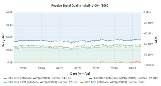
Figure 7.
Performance in terms of SNR of Link 2.
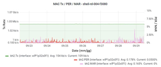
Figure 8.
Performance in terms of PER of Link 2.
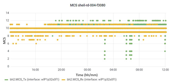
Figure 9.
Performance in terms of MCS of Link 2.
Link 3 connects the node with ID sheil-rd-005-f8627 to the node with ID sheil-rd-006-spfhc represented as Node 3 and Node 4 in Figure 4, respectively. Figure 10, Figure 11 and Figure 12 illustrate again, among other parameters, the SNR (green line in Figure 10), the performance in terms of PER (red line in Figure 11) and the MCSs (yellow circles in Figure 12) at the receiver node, i.e., node sheil-rd-006-spfhc. From these figures we can conclude that the average SNR is 18.5 dB, the PER on average is 0.56% and the average MCS is 11.
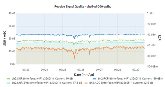
Figure 10.
Performance in terms of SNR of Link 3.
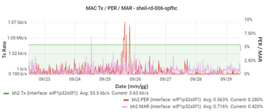
Figure 11.
Performance in terms of PER of Link 3.
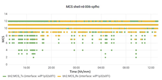
Figure 12.
Performance in terms of MCS of Link 3.
5.3. Discussion
Table 3 summarizes all the results illustrated in the previous subsections. Specifically, based on the monitoring carried out through Grafana, in the table we can observe that the longest link achieves an SNR of 14 dB and can use MCS 9 guaranteeing a PER of approximately 0.2%. On the other hand, based on the simulations, the link is characterized by the same PER and MCS when it can achieve 15 dB SNR. Note that radio-to-radio variations of 1–2dB on the SNRs monitored through Grafana are expected due to manufacturing tolerances and, therefore, the longest link modelled through MATLAB can be considered validated. Moreover, in the table we can observe that the short link, based on the monitored information, achieves an SNR of 18.5 dB and can use MCS 11 guaranteeing a PER of approximately 0.6%. On the other hand, based on the simulations, this link in the case of 18.5 dB SNR can use MCS 9 in order to guarantee the same value of PER. Note that, again considering a possible radio-to-radio variation of 1–2 dB on the monitored values, the short link could reach MCS 10 guaranteeing the same value of PER computed through Grafana. Therefore, even taking into account monitoring errors due to manufacturing tolerances, there is still a reduction in terms of maximum available throughput of 20% in the short link, which can provide 3080 Mbps in the simulator and 3850 Mbps in Grafana (see Table 1).
Table 3.
Results Comparison.
In summary, our simulation results, therefore, provide a variable picture in terms of corroborating the performance for the short link. One explanation of this could be that the actual nodes are performing better under certain circumstances and this needs to be programmed into our simulator. Other explanations include minor differences in the physical deployment of the equipment (e.g., alignment) or environmental factors that affect link performance. These results, therefore, generally validate our simulations but highlight the issues in predicting link performance in such a dynamic environment and with a limited set of links to evaluate. Our immediate next steps are, therefore, to gather more data on the configuration and performance of the nodes as the deployment continues and monitor them further to refine our models over time.
6. Conclusions and Further Work
The popularity of wireless communications for a wide range of use cases means that 5G technologies are likely to become increasingly ubiquitous over time, both in traditional MNO deployments but also in a range of other scenarios, from 5G NPN for supporting IIoT to community-owned networks. However, the vast range of technologies and techniques that represent 5G, both in the core and at the edge, make it very complicated to define exactly what 5G ‘looks like’ and how it performs in every situation.
In Liverpool, a 5G network has been deployed by a consortium including the local council and healthcare providers, technology firms and academic institutions to support healthcare and community care services. This network leverages the existing CCTV fibre network and extends it using mmWave backhaul links into areas of the city where connectivity is required. These backhauls are built using 802.11ad point-to-point links that offer up to multi-gigabit services but are susceptible to the restrictions of 60 Ghz communications.
In an effort to understand this better, we built a simulator in MATLAB to model the behaviour of these links under a range of conditions, and compared our results to the real-world deployments to validate our findings. Our results show that some links conform to our model very well, while others are somewhat unpredictable. This difference could be due to manufacturing tolerances or variations in link quality over short distances. This is a valuable contribution to ongoing 5G deployment efforts that utilize this technology, as real-world characteristics for 60 GHz link performance will help to refine node placement and configuration. It also provides useful insights to the research community on the effectiveness of novel private and community 5G-utilizing heterogeneous technologies.
Over time, we aim to continually improve our models through further validation to generalize our model such that it can be used as a general-purpose tool for network planning or as a basis for further work to examine network optimization. We would also be interested in evaluating the potential impact of 802.11ay-based links in this environment and conducting a comparative analysis of their performance.
Author Contributions
Conceptualization, M.M. and A.R.; methodology, M.M., A.R. and O.T.; software, O.T and A.R.; validation, O.T. and A.R.; formal analysis, O.T. and A.R; investigation, M.M. and A.R; writing—original draft preparation, M.M. and A.R.; writing—review and editing, M.M. and A.R.; visualization, O.T.; supervision, M.M. and A.R; project administration, M.M.; funding acquisition, M.M. All authors have read and agreed to the published version of the manuscript.
Funding
This research received no external funding.
Institutional Review Board Statement
Not applicable.
Informed Consent Statement
Not applicable.
Data Availability Statement
Not applicable, the study does not report any data.
Conflicts of Interest
The authors declare no conflict of interest.
References
- Kodjo, A. Design and Optimization of Wireless Backhaul Networks; Université Nice Sophia Antipolis: Nice, France, 2014. [Google Scholar]
- Kim, J.; Kim, J.-K. Achievable rate estimation of IEEE 802.11 ad visual big-data uplink access in cloud-enabled surveillance applications. PLoS ONE 2016, 11, e0167447. [Google Scholar] [CrossRef] [Green Version]
- TTrakadas, P.; Sarakis, L.; Giannopoulos, A.; Spantideas, S.; Capsalis, N.; Gkonis, P.; Karkazis, P.; Rigazzi, G.; Antonopoulos, A.; Cambeiro, M.A.; et al. A Cost-Efficient 5G Non-Public Network Architectural Approach: Key Concepts and Enablers, Building Blocks and Potential Use Cases. Sensors 2021, 21, 5578. [Google Scholar] [CrossRef]
- Rostami, A. Private 5G Networks for Vertical Industries: Deployment and Operation Models. In Proceedings of the IEEE 5G World Forum (5GWF), Dresden, Germany, 30 September–2 October 2019; pp. 433–439. [Google Scholar] [CrossRef]
- Aijaz, A. Private 5G: The Future of Industrial Wireless. IEEE Ind. Electron. Mag. 2020, 14, 136–145. [Google Scholar] [CrossRef]
- Strinati, E.C.; Haustein, T.; Maman, M.; Keusgen, W.; Wittig, S.; Schmieder, M.; Barbarossa, S.; Merluzzi, M.; Klessig, H.; Giust, F.; et al. Beyond 5G Private Networks: The 5G CONNI Perspective. In Proceedings of the 2020 IEEE Globecom Workshops (GC Wkshps), Taipei, Taiwan, 7–11 December 2020; pp. 1–6. [Google Scholar] [CrossRef]
- Patwary, M.N.; Nawaz, S.J.; Rahman, A.; Sharma, S.K.; Rashid, M.; Barnes, S.J. The Potential Short- and Long-Term Disruptions and Transformative Impacts of 5G and Beyond Wireless Networks: Lessons Learnt From the Development of a 5G Testbed Environment. IEEE Access 2020, 8, 11352–11379. [Google Scholar] [CrossRef]
- Larsen, L.M.P.; Checko, A.; Christiansen, H.L. A Survey of the Functional Splits Proposed for 5G Mobile Crosshaul Networks. IEEE Commun. Surv. Tutor. 2018, 21, 146–172. [Google Scholar] [CrossRef] [Green Version]
- Liverpool 5G Health and Social Care Testbed, Overview, January 2020. Available online: https://liverpool5g.org.uk/wp-content/uploads/2021/07/Liverpool-5G-Heath-and-Social-Care-Testbed-Overview.pdf (accessed on 15 December 2021).
- Srinivasa, S.; Haenggi, M. Throughput-delay-reliability tradeoffs in multihop networks with random access. In Proceedings of the 2010 48th Annual Allerton Conference on Communication, Control, and Computing (Allerton), Monticello, IL, USA, 29 September–1 October 2010; pp. 1117–1124. [Google Scholar] [CrossRef]
- Brienza, S.; de Guglielmo, D.; Anastasi, G.; Conti, M.; Neri, V. Strategies for optimal MAC parameter setting in IEEE 802.15. 4 wireless sensor networks: A performance comparison. In Proceedings of the 2013 IEEE Symposium on Computers and Communications (ISCC), Split, Croatia, 7–10 July 2013; pp. 898–903. [Google Scholar]
- Gao, Z.; Dai, L.; Mi, D.; Wang, Z.; Imran, M.A.; Shakir, M.Z. MmWave massive-MIMO-based wireless backhaul for the 5G ultra-dense network. IEEE Wirel. Commun. 2015, 22, 13–21. [Google Scholar] [CrossRef] [Green Version]
- Legg, P.; McConnell, R. Meshed Backhauling of Small Cells Using IEEE802. 11ad at 60GHz. In Proceedings of the 2018 European Conference on Networks and Communications (EuCNC), Ljubljana, Slovenia, 18–21 June 2018; pp. 393–397. [Google Scholar]
- Seker, C.; Güneser, M.T.; Ozturk, T. A Review of Millimeter Wave Communication for 5G. In Proceedings of the 2018 2nd International Symposium on Multidisciplinary Studies and Innovative Technologies (ISMSIT), Ankara, Turkey, 19–21 October 2018; pp. 1–5. [Google Scholar]
- Kuo, P.-H.; Mourad, A. Millimeter wave for 5G mobile fronthaul and backhaul. In Proceedings of the 2017 European Conference on Networks and Communications (EuCNC), Oulu, Finland, 12–15 June 2017; pp. 1–5. [Google Scholar]
- Liverpool 5G Health and Social Care Testbed, Developing the Network, January 2020. Available online: https://liverpool5g.org.uk/wp-content/uploads/2021/07/Liverpool-5G-Health-and-Social-Care-testbed-Developing-the-Network.pdf (accessed on 15 December 2021).
- UK5G. The 5G Smart Tourism Project. 2019. Available online: https://uk5g.org/discover/testbeds-and-trials/5g-smart-tourism/ (accessed on 15 December 2021).
- W. 5G. Worcestershire 5G Testbed Project. 2019. Available online: https://www.wlep.co.uk/current-projects/worcestershire-5g/ (accessed on 15 December 2021).
- Sakaguchi, K.; Mohamed, E.M.; Kusano, H.; Mizukami, M.; Miyamoto, S.; Rezagah, R.E.; Takinami, K.; Takahashi, K.; Shirakata, N.; Peng, H.; et al. Millimeter-Wave Wireless LAN and Its Extension toward 5G Heterogeneous Networks. IEICE Trans. Commun. 2015, 98, 1932–1948. [Google Scholar] [CrossRef] [Green Version]
- Nitsche, T.; Cordeiro, C.; Flores, A.B.; Knightly, E.W.; Perahia, E.; Widmer, J.C. IEEE 802.11 ad: Directional 60 GHz communication for multi-Gigabit-per-second Wi-Fi. IEEE Commun. Mag. 2014, 52, 132–141. [Google Scholar]
- Schultz, B. 802.11 ad–WLAN at 60 GHz–A Technology Introduction; Rohde & Schwarz: Munich, Germany, 2013. [Google Scholar]
- Assasa, H.; Widmer, J. Implementation and Evaluation of a WLAN IEEE 802.11 ad Model in ns-3. In Proceedings of the Workshop on ns-3; ACM: New York, NY, USA, 2016; pp. 57–64. [Google Scholar]
- Group, I.W. IEEE Standard for Information Technology–Telecommunications and Information Exchange between Systems–Local and Metropolitan Area Networks–Specific Requirements–Part 11: Wireless LAN Medium Access Control (MAC) and Physical Layer (PHY) Specifications Amendment 6: Wireless Access in Vehicular Environments; IEEE Std.: New York, NY, USA, 2010; Volume 802. [Google Scholar]
- Simoens, S.; Pellati, P.; Gosteau, J.; Gosse, K.; Ware, C. The evolution of 5GHz WLAN toward higher throughputs. IEEE Wirel. Commun. 2003, 10, 6–13. [Google Scholar] [CrossRef]
- Liu, Q.; Zhou, S.; Giannakis, G. Queuing with adaptive modulation and coding over wireless links: Cross-Layer analysis and design. IEEE Trans. Wirel. Commun. 2005, 4, 1142–1153. [Google Scholar] [CrossRef]
- Alouini, M.-S.; Goldsmith, A.J. Adaptive Modulation over Nakagami Fading Channels. Wirel. Pers. Commun. 2000, 13, 119–143. [Google Scholar] [CrossRef]
- Holland, G.; Vaidya, N.; Bahl, P. A rate-adaptive MAC protocol for multi-hop wireless networks. In Proceedings of the 7th Annual International Conference on Mobile Computing and Networking; ACM: New York, NY, USA, 2001; pp. 236–251. [Google Scholar]
- Qiao, D.; Choi, S.; Shin, K.G. Goodput analysis and link adaptation for IEEE 802.11 a wireless LANs. IEEE Trans. Mob. Comput. 2002, 99, 278–292. [Google Scholar] [CrossRef] [Green Version]
- Kamerman, A.; Monteban, L. WaveLAN®-II: A high-performance wireless LAN for the unlicensed band. Bell Labs Tech. J. 1997, 2, 118–133. [Google Scholar] [CrossRef]
- Ali, E.; Ismail, M.; Nordin, R.; Abdulah, N.F. Beamforming techniques for massive MIMO systems in 5G: Overview, classification, and trends for future research. Front. Inf. Technol. Electron. Eng. 2017, 18, 753–772. [Google Scholar] [CrossRef]
- Murray, B.P.; Zaghloul, A.I. A survey of cognitive beamforming techniques. In Proceedings of the 2014 United States National Committee of URSI National Radio Science Meeting (USNC-URSI NRSM), Boulder, CO, USA, 8–11 January 2014; p. 1. [Google Scholar]
- IEEE Std 802.11ad™-2012 IEEE Standard for Information Technology—Telecommunications and Information Exchange between Systems—Local and Metropolitan Area Networks—Specific Requirements—Part 11: Wireless LAN Medium Access Control (MAC) and Physical Layer (PHY) Specifications. Amendment 3: Enhancements for Very High Throughput in the 60 GHz Band; IEEE Std.: New York, NY, USA, 2013.
- Maltsev, A.; Erceg, V.; Perahia, E.; Hansen, C.; Maslennikov, R.; Lomayev, A.; Sevastyanov, A.; Khoryaev, A.; Morozov, G.; Jacob, M.; et al. Channel Models for 60 GHz WLAN Systems; IEEE Standard 802.11-09/0334r8; IEEE Std.: New York, NY, USA, 2010. [Google Scholar]
- Maltsev, A.; Pudeyev, A.; Gagiev, Y.; Lomayev, A.; Bolotin, I.; Johnsson, K.; Sakamoto, T.; Motozuka, H.; Gentile, C.; Papazian, P.; et al. Channel Models for IEEE 802.11ay; IEEE Standard 802.11-15/1150r9; IEEE Std.: New York, NY, USA, 2017. [Google Scholar]
Publisher’s Note: MDPI stays neutral with regard to jurisdictional claims in published maps and institutional affiliations. |
© 2022 by the authors. Licensee MDPI, Basel, Switzerland. This article is an open access article distributed under the terms and conditions of the Creative Commons Attribution (CC BY) license (https://creativecommons.org/licenses/by/4.0/).