Abstract
The Internet architecture has been undergoing a significant refactoring, where the past preeminence of transit providers has been replaced by content providers, which have a ubiquitous presence throughout the world, seeking to improve the user experience, bringing content closer to its final recipients. This restructuring is materialized in the emergence of Massive Scale Data Centers (MSDC) worldwide, which allows the implementation of the Cloud Computing concept. MSDC usually deploy Fat-Tree topologies, with constant bisection bandwidth among servers and multi-path routing. To take full advantage of such characteristics, specific routing protocols are needed. Multi-path routing also calls for revision of transport protocols and forwarding policies, also affected by specific MSDC applications’ traffic characteristics. Experimenting over these infrastructures is prohibitively expensive, and therefore, scalable and realistic experimentation environments are needed to research and test solutions for MSDC. In this paper, we review several environments, both single-host and distributed, which permit analyzing the pros and cons of different solutions.
1. Introduction
The historical client-server Internet model, based on a hierarchical network of networks with strong Tier-1 and Tier-2 Transit Providers, has been experiencing a gradual transition to a content-driven network [1]. Over the Top (OTT), Cloud, and Content Delivery Network (CDN) providers have promoted the deployment of ubiquitous massive scale data centers (MSDC), which may host hundreds of thousands of physical servers, which in turn may deploy huge amounts of virtual machines (VMs) and containers, widely used for developing cloud-based applications and services. The basic functionality of the MSDC includes computing, storing, and replicating data, using message exchange among servers over the supporting communication infrastructure.
Conveying packets in these infrastructures demands a vast communication scale and bandwidth much higher than the historical Internet WAN traffic. Consequently, it is necessary to design and develop specific data center routing, transport, and forwarding solutions to meet such communication requirements. Data center traffic is usually classified as East–West and North–South. East–West traffic refers to traffic among servers, while North–South traffic refers to traffic between applications running in the data center and Internet users. It is worth noting that East–West traffic represents as high as 85% of overall traffic [2].
Therefore, looking for constant bisection bandwidth (i.e., the same capacity available for any-to-any communication among servers) fueled the resurgence of non-blocking Clos networks [3]. These networks are built up from multiple stages of switches, where each switch in a stage is connected to all the switches in the next stage, which provides extensive path diversity. A fat-tree data center topology is a particular case of a Clos network, where high bisection bandwidth is achieved by interconnecting commodity switches; fat-trees are briefly presented in Section 2.1, please refer to [4,5,6] for further information.
Fat-tree topologies provide extensive path diversity, where the combined link bandwidth is potentially much higher than the traditional shortest path. To take advantage of such path diversity, Equal Cost Multi-Path (ECMP) solutions are implemented [7]. Nevertheless, ECMP is not possible under pure switched (e.g., Layer 2) Spanning-Tree-based networks, and therefore, routed (e.g., Layer 3) solutions must be in place.
Different routing protocols for fat-tree topologies have been proposed, including BGP in the data center [8], Openfabric (IS-IS with flooding reduction) [9], and a couple of routing protocols under active development by the IETF, namely, Routing in Fat Trees (RIFT) [10,11] and Link State Vector Routing (LSVR) [12]. These protocols seek to combine the valuable features from both link-state and distance-vector algorithms, together with the knowledge of the underlying topology.
Introducing new features, debugging protocol implementations, or testing different topologies and scenarios demands testing and development environments. For obvious reasons, it would be impracticable to experiment over existing data center facilities; moreover, researchers cannot access real infrastructures with the necessary scale to experiment with the protocols mentioned above. Therefore, other approaches are needed; namely, (i) model-based verification and (ii) emulation or simulation-based testing.
In this regard, and adopting the emulation approach, our contribution is threefold. Firstly, in Section 3, we analyze different experimental environments suitable for dense fat-tree topologies. Then, in Section 4, we provide specific configuration setups for experimenting with fat-trees over these environments, introducing the problem of convergence detection, which is important to correctly stop experiments and compute performance metrics such as message complexity. Finally, in Section 5, we perform a suite of experiments over the environments mentioned above and provide a comprehensive analysis that may help researchers and practitioners to choose the experimental setup which satisfies their needs.
It is worth mentioning that the tools developed in this work are freely available for the community, allowing reproducibility and further improvement. It should also be taken into account that, although this work is focused on dense fat-tree type topologies, emulation environments can be used in multiple use cases, including typical WAN network scenarios, among others. However, the case undertaken can be considered a lower bound for node scalability since, due to the type of topologies emulated, not only the number of nodes is important, but fundamentally the number of interfaces that must be emulated.
Observe that routing with ECMP support over the dense fat-tree fabric (i.e., routing infrastructure) is only the first step for traffic control in the data center. Once the routing is in place, both forwarding (at the switch level) and transport (at the application level) shall be analyzed to fulfill the traffic demands, which are very diverse among different applications. We briefly analyze these aspects and discuss some possible paths for future work in Section 6.
2. Routing in the Data Center
To have adequate routing and forwarding, it is imperative to fully exploit the topological characteristics of fat trees. Some basic requirements should be satisfied: forwarding loops avoidance, rapid failure detection, efficient network utilization (e.g., spanning-tree solutions are not acceptable), routing scalability (in addition to physical scalability). Based on this, a layer two fabric will not scale, and therefore, layer three (e.g., routing) solutions should be adopted.
Another important requirement is virtual machines and container migration between different servers keeping their IP addresses unchanged. This imposes that a transparent layer-two fabric must connect the data center, implemented as an overlay over the layer-three environment [5].
In principle, being the data center a single administrative domain, the candidates to fulfill the routing role are popular link-state IGPs. However, as they have been designed for arbitrary topologies, the flood of link-state advertisements may suffer from scalability issues. Therefore, the possible solutions should entail reducing the message flooding, exploiting the topology knowledge, or using other routing algorithms. In this regard, the following routing protocols will be considered in this work: BGP with a specific configuration for the data center, link-state algorithms with flooding reduction, and ongoing Internet Engineering Task Force (IETF) efforts, namely Routing in Fat Trees (RIFT) and Link State Vector Routing (LSVR), which are leveraging link-state and distance-vector advantages to design specific routing algorithms for data centers.
In this paper, we only considered distributed control plane solutions, i.e., routing protocols. Consequently, logically centralized Software-Defined Networking (SDN) solutions will not be analyzed.
2.1. Fat-Tree Topology
A tree-based topology is one of the most representative topology classes for Data Center Networks (DCNs), including basic tree, fat-tree, and 5-stage Clos. A fat-tree data center topology is a particular case of a Clos network [3] where high bisection bandwidth is achieved by interconnecting commodity switches. The fat-tree topology idea was initially proposed for supercomputing [13] and adapted for data center networks [4,5].
Fat-tree networks are topologically partially ordered graphs and “level” denotes the set of nodes at the same height in such a network. In Figure 1, a fat tree with three levels is depicted. The top-level is called Top of Fabric (ToF) or Core and comprises Core switches. The immediately lower level (aggregation level) is composed of Spine switches. Finally, at level zero (edge level), there are Leaf switches. Let us introduce the concept of Point of Delivery (PoD). A PoD is a subset of a fat-tree network typically containing only Leaf and Spine nodes that are fully interconnected. A node in a PoD communicates with nodes in other PoDs via the ToF.
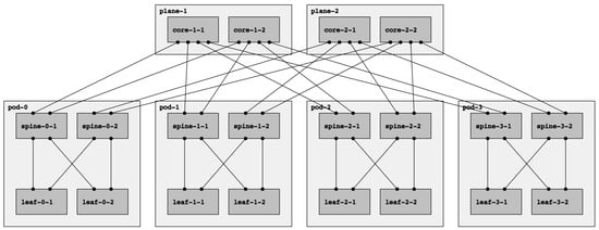
Figure 1.
A fat-tree topology with : four-port switches arranged in four PoDs with four switches each.
The fat-tree topology consists of k PoDs, numbered left to right from Pod-0 to Pod-(k-1), with three layers of switches: leaf switches, spine switches, and core switches. Thus, in a k PoD fat-tree topology, there are k switches (each with k ports) in each PoD arranged in two layers of switches, one layer for leaf switches and the other for spine switches. Each leaf switch is connected to spine switches. There are core switches, each of which connects to k PoDs. With this topology description, the k factor can be used to calculate the number of nodes in each level of the fabric. Table 1 adopted from [5] summarizes the topological information for a fat tree in terms of the k factor.

Table 1.
Fat-Tree topology summary [5].
Note that there are two types of fat trees: single-plane and multi-plane. In a multi-plane topology (the fat-tree type described above), each ToF node connects to k PoDs. Contrarily, each ToF node connects to every spine node in a single-plane fat tree. With this configuration, even if all ToFs but one are down, the connectivity between leaves is guaranteed. However, it presents a significant drawback: the number of ports needed for each ToF increase significantly, which might be unfeasible if k is too large. In this paper, we will always refer to multi-plane fat-tree topologies, following the notation introduced above and describing the fat-tree in terms of the k factor.
Observe that there are other terminologies for describing fat trees, for example, the one used in the RIFT (Routing In Fat Trees) protocol draft [10]. That terminology specifies three parameters: , describing the number of ports pointing north or south for the leaf nodes, and , which describes the same for the spine nodes. Finally, they denote by R the redundancy factor, i.e., the number of links from a ToF to a PoD. Following this notation, the topology shown in Figure 1 can be described as , , .
Deploying a topology with these properties has certain benefits for the data center. First, all switches are of the same type with the same number of ports, minimizing downtime periods and reducing operating costs (OPEX). Moreover, there are multiple paths between any pair of hosts. In particular, in a k fat-tree topology, there are paths between two Leaf switches within a pod (intra-pod), and there are k paths between any two Leaf switches that are across pods (inter-pod). This multi-path solution inspires to explore the Equal-cost multi-path routing (ECMP) routing strategy, which allows dividing the fabric traffic load more efficiently.
2.2. Link-State Routing
Link-state routing protocols, such as OSPF [14] and IS-IS [15], have been for many years, and continue to be, the state-of-the-art Interior Gateway Protocols (IGPs) for Internet Service Provider (ISP) backbones. Nevertheless, a link-state routing network protocol cannot easily scale beyond a thousand routers, mainly due to the Link State Advertisements (LSAs) flooding, even though they are hierarchical protocols by design [16]. Nowadays, data centers can easily accommodate tenths of thousands of servers, which means a few thousand switches/routers. For example, for fifty thousand servers, more than four thousand switches are needed (see the formula in [5]); more efficient Clos network realizations [17] claim to demand around 2400 switches for a hundred thousand bare metal servers. In the last several years, the industry and the research community have been working on efficient ways to reduce flooding in this type of protocols; for example, Openfabric is an IS-IS Optimal Distributed Flooding for Dense Topologies [9].
2.3. BGP in the Data Center
Among other reasons, the choice of BGP [18] as a routing protocol for data centers is motivated by (i) the presence of robust implementations, (ii) reduced control plane flooding, (iii) native support for many protocols, such as IPv4 and IPv6, Multiprotocol Label Switching (MPLS), and VPNs, and (iv) multi-path support. BGP was designed for single-path inter-domain routing, and, therefore, it must be specifically configured for multi-path data center routing. Indeed, the dense connectivity of the data center network is vastly different from the relatively sparse connectivity among administrative domains on the Internet. In inter-domain routing, stability is preferred over rapid notification of changes. Therefore, BGP speakers typically hold off sending notifications about changes for a while. Instead, operators want routing updates to be as fast as possible in a data center network. In addition, due to its default behavior as a path-vector protocol, any single link failure can result in a large number of BGP messages passing between all the nodes, a situation that should be avoided in data centers. Finally, by default, BGP speakers build a single best path when a prefix is learned from many different ASes (because they typically represent a separate administrative domain), while in data centers, multiple paths selection is needed. BGP configuration needs to be specifically tailored for the data center. Firstly, eBGP is preferred over iBGP since it is simpler to understand and configure, especially for multi-path support. Secondly, Autonomous System numbering in the data center is different from the traditional one. Only private ASN is used and, to potentially support more than 1024 nodes, the 4-byte ASN address space [19] is preferred. However, even though the most straightforward approach to ASN assignment is that every router is assigned a different one, this approach leads to the path hunting problem, which is a variation of the count-to-infinity problem suffered by distance vector protocols [20]. To avoid this problem, the practical guideline for ASN assignment in a fat-tree topology is the following: (1) Each Leaf node is assigned a distinct ASN; (2) Spines in the same PoD have the same ASN that is different for each PoD; (3) All ToFs share the same ASN. However, the drawback of this assignment model is that route aggregation is not possible because it can lead to black-holing. Thirdly, some additional tweaks are needed; that is, the only attribute to consider in the decision process is the AS_PATH, and, in order to support Equal Cost Multi-Path (ECMP), a group of routes for a given destination is considered equal if the AS_PATH length is the same, relaxing the criterion that the ASNs in the AS_PATH should match exactly. Refer to [8,21] for an in-depth description.
2.4. RIFT: Routing in Fat Trees
A basic reasoning behind the development of specific routing protocols for the data center is that the awareness of the underlying fat-tree topology may be used as an advantage to reduce control messages flooding. In this regard, given the North–South, East–West orientation, RIFT floods flat link-state information northbound only so that each level obtains the full topology of its South levels. However, link-state information is, with some exceptions, never flooded East–West or back South again. This characteristic defines RIFT as an anisotropic protocol (i.e., the information is not evenly distributed but summarized along the N–S gradient), where the nodes do not receive the same information from multiple directions simultaneously. Indeed, since there is an understanding of the topological dimension, reachability information is not received “freely” on any link. Therefore, under normal conditions, RIFT does not need to tie-break the same reachability information using some kind of distance metric, which leads ultimately to hop-by-hop forwarding to shortest paths only. Moreover, its computation principles (south forwarding direction is always preferred) lead to valley-free forwarding behavior, hence loop-free, allowing nodes to use all feasible paths (i.e., multi-path forwarding), using all the available bandwidth. Consequently, each fabric level obtains the full topology of its South levels and has one default route to the higher level. This allows a highly desirable aggregation of routes but can lead to the black-hole of traffic or even to partial network partitioning in case of misconfiguration or while failures are being resolved. RIFT addresses these problems by implementing an automatic disaggregation of prefixes in case of link and node failures. This mechanism is based on positive non-transitive disaggregation and negative transitive disaggregation. The former is used by a node that detects that its default IP prefix covers one or more prefixes that are reachable through it but not through one or more other nodes at the same level. Thus, it has to advertise those prefixes southbound to prevent traffic black-holing explicitly. It is non-transitive because the effects of this type of disaggregation are always contained in a single level of the fabric. The latter is used by a ToF node when it discovers that it cannot reach a fallen Leaf in a multi-plane topology. Thus, it has to disaggregate all the prefixes of such Leaf, sending them southbound. This type of disaggregation is transitive because if a node receives a negative disaggregation for a specific prefix from its parents, it has to propagate such disaggregation southbound to reach the Leaf. This is necessary since Leaves connected to multiple planes may have to choose the correct plane to prevent traffic black-holing. For details on RIFT mechanism and concepts, such as South Reflection, Flood Repeater, Bandwidth Adjusted Distance, and Thrift packet encoding, please refer to [10].
2.5. LSVR: Link State Vector Routing
LSVR aims to overcome the limits of BGP. Indeed, the usage of eBGP avoids using Route Reflectors, requiring a heavy and error-prone manual configuration of peerings; to this end, different peer discovery alternatives have been proposed under the LSVR working group. Moreover, the hop-by-hop nature of the eBGP decision process imposes delays to overall convergence and prevents omniscient views of the fabric. In this regard, LSVR proposes replacing the rule-based BGP decision process with a Shortest Path First algorithm and advocates for using the BGP-LS [22] extensions for communication with external controllers. At the time of this writing, ongoing LSVR implementations are still unavailable, so LSVR will not be tested. For further information, see [12].
2.6. Switching Overlay
In addition to the infrastructure routing use case, migrating Virtual Machines (VM) between different servers keeping their IP addresses unchanged (i.e., maintaining their attachment to a given L3 subnet) is a major requirement from the application point of view, which is completely unaware of the underlying connectivity. It implies that the data center is connected by a transparent layer two fabric, which eventually implements L2 VLANs. Therefore, this requirement demands implementing layer two emulation over layer three environment, using solutions such as VXLAN [23] or Ethernet Virtual Private Networks (EVPN) [24].
3. Experimentation Environments
The networking community has been progressively adopting the NetDevOps model, which implies incorporating the concepts of continuous development and integration from the software industry into the network management lifecycle, and, in particular, of massive-scale data center communication networks (DCNs). In fact, various industrial players have developed emulation environments to experiment with new technologies before incorporating them into operation, including Nokia [25], Cisco [26], Nvidia/Cumulus [27], among others. In addition, some of these environments have been presented to the research community, such as Microsoft CrystalNet [28] and Huawei NetGraph [29], but, unfortunately, they are proprietary software, and therefore their results can not be reproduced.
In any case, there are numerous initiatives in line with the development and continuous integration model strongly guided by programming interfaces (also called network to code), which respond to the need to test the new capabilities and improvements incorporated into network devices in controlled environments.
At this point, it is important to clarify the differences between network virtualization, emulation, and simulation. While Network Virtualization consists of using a virtual device in a production network as a replacement for a physical device, Network Emulation consists of emulating a production device with a virtual equivalent for testing or training, running the same software images as the production device. On the other hand, Network Simulation seeks to mimic the production device functionality implemented in a completely different environment, e.g., a discrete event simulator. It is also important to point out that, even though emulation runs the same image as production software, the underlying resources are inherently less powerful; for instance, while control plane software (such as routing and signaling protocols) usually runs in general-purpose CPUs, data plane forwarding is implemented in specialized ASICs, which can not be emulated. Therefore, while emulation is a very appealing technique for control plane testing and debugging, the data plane emulation results can only be taken into account as an approximation to the behavior of the production network, but it is not possible to use them to measure performance.
In addition to emulation and simulation, network-control-plane debugging may be performed using model-based verification [30]. Even though these methods may theoretically explore every possible execution path, they cannot consider the impact of software errors since they perform static configuration analysis and assume correct, error-free implementations. According to [31], software errors have a non-negligible impact on data center failures, accounting for 12% of failures in Facebook data centers. On the other hand, in emulation-based testing, network devices run unmodified network firmware, and therefore they are exposed to real-life software errors.
Popular network simulators such as ns-3 [32] or OMNeT++ [33], which have strong networking frameworks, are frequently used by network operators, developers, and researchers seeking to evaluate, test, and replicate their protocol proposals, service deployments, and architectures. Nevertheless, the capabilities of simulations are not enough to cover some requirements imposed by the actors, such as the deployment of heterogeneous network elements, the inclusion of emerging technologies, or users’ behavior. Simulation is also considered a weak method for testing new proposals because it does not incorporate real-world network stacks (e.g., Free Range Routing [34]) and does not support the execution of unmodified applications. Moreover, they fail to provide results close to the real behavior of current networks, which are more non-deterministic and complex [35,36].
Consequently, emulation platforms are often considered to outperform the limitations of network simulation. Emulation aims to improve experimentation fidelity by enabling the reuse of real-world protocols and applications within a virtual network. There are a large variety of networks emulators, each one with its technologies, advantages, and drawbacks.
Despite the advantages described for emulators over simulators, it is important to remark the major drawback of emulators: the increased complexity of emulated systems limits their scalability. This manifests in the support restriction for large network sizes and link speeds in real-time.
The election of an experimentation environment depends on multiple factors and may be different for network operators, researchers, and other actors. This decision may involve network simulators, emulators, and other networking tools. The following subsections introduce the networking tools that compose the emulation environments described in this work. We present both single-host and distributed emulation environments, traffic analysis tools, and the routing protocols suite used in our assessment.
3.1. Kathará
Kathará [37,38] is a network emulation system that accurately reproduces the behavior of a real system. It leverages upon Docker containers [39] to implement devices, allowing Kathará to run on mainstream Operating Systems such as Windows, Linux, and macOS. Moreover, using containers to emulate devices represents a lightweight alternative to standard virtualization solutions, which usually introduce costly overhead.
With Docker containers, the management of different filesystem images is simplified, allowing devices to use different images in the same network scenario.
This flexibility enables the network nodes to have different behaviors. For example, a node with the standard routing protocols provided by well-known network routing suites such as Quagga [40] or its industry-level branch Free Range Routing (FRR) [34,41] may be accommodated, just by selecting the appropriate Docker image. Moreover, a node can be provided with a custom Docker image with all the routing protocols and network tools required. In addition, Kathará offers a set of pre-built images that can be used to run several services such as standard routing protocols, control-plane programmable network nodes, data-plane programmable switches, among others, which can be accessed at [42].
The orchestration of emulations on Kathará is completely based on configurations. It integrates tools that automatize these configurations but does not offer any built-in programmability for this task.
3.2. Megalos
Kathará supports different virtualization managers, particularly when using Kubernetes [43] as virtualization technology is called Megalos [44], which inherits all the advantages of using containers and Docker images.
As well as Kathará, Megalos supports the implementation of virtual network scenarios consisting of virtual devices, which in this context are named by the authors as Virtual Network Functions (VNFs), where each VNF may have several L2 interfaces assigned to virtual LANs. By exploiting Virtual Extensible LAN (VXLAN) and EVPN BGP, Megalos guarantees the segregation of each virtual LAN traffic from the traffic of other LANs and Internet traffic. In addition, this key characteristic permits distributing VNFs (i.e., devices) in a cluster of servers, where the L2 overlay permits separating emulation traffic from the cluster traffic. The emulation distribution into multiple nodes permits Megalos to emulate large-scale network infrastructures where a significant quantity of VNFs and virtual LANs are required.
Cooperation with the developers of both Kathará and Megalos has recently produced Sibyl [45], a software framework based on these tools, tailored to perform a large number of experiments on several virtual fat-tree configurations. Sibyl implements a methodology specifically devised for testing routing protocols in fat-tree networks, including VFTGen [46], a tool to generate fat-tree topologies, RT Calculator, a tool to detect protocol convergence, and utilities for collecting control plane data and processing results. These tools, which have been used as inspiration for the methodology developed for the rest of the emulation environments, will be further referred to in the rest of the paper.
3.3. Mininet
Mininet [47,48] is a network emulation orchestration system. It runs a collection of end-hosts, switches, routers, and links on a single Linux kernel. It uses lightweight virtualization, which permits to emulate network infrastructure in a single host, running the same kernel, system, and user code. Mininet is open source, easy to deploy, and provides a programmable interface to define and build network configurations.
The Linux container mechanism used by Mininet allows groups of processes to have independent namespaces for system resources (e.g., network interfaces and file systems) running on the same kernel. For each virtual host, Mininet creates a container attached to a network namespace. Each network namespace holds a virtual network-interface connected to a software switch via virtual Ethernet links.
Mininet presents performance bounds in commodity servers that satisfy the demands of the general network tests. It achieves high aggregated bandwidths and low median round trip times even in demanding scenarios where more than a thousand hosts are included in the emulated topologies [35].
Another important feature of Mininet is its programmability. In this regard, Mininet integrates on its core a Python API. Hence, Python is used for orchestration, but emulation is performed by compiled C code. The API is well documented, easy to use, and because it is integrated with the Mininet core, everything can be built with it.
Mininet also integrates several SDN elements. For example, in [49], they combine Mininet and the ONOS [50] controller to present a scalability analysis. Due to the above characteristics, Mininet has become one of the reference emulation tools.
3.4. CORE: Common Open Research Emulator
The Common Open Research Emulator [51] is a real-time network emulator. It emulates routers, PCs, and other hosts and simulates the network links between them. With this tool, the emulated networks can be connected in real-time to physical networks and routers. This type of functionality is not common in the available emulators and it allows us to increase the size of physical test networks. CORE also can distribute the emulation on one or more Linux machines and provides an environment for running real applications and protocols, taking advantage of tools provided by the Linux operating system.
The architecture consists of a GUI for drawing topologies, a services layer that instantiates lightweight virtual machines, and an API for tying them together. Topologies can also be scripted using the Python language. It has enabled CORE to be extended to work with FreeBSD jails, Linux OpenVZ containers, and Linux network namespace containers. In [52], these different platforms are compared in terms of virtualization features and performance.
Recently, CORE incorporated a Python API like Mininet. Writing Python scripts offers a rich programming environment with complete control over all aspects of the emulation. In general, a CORE Python script does not connect to the CORE daemon; in fact, the core-daemon is just another Python script that uses the CORE Python modules and exchanges messages with the GUI. This API provides many functionalities, but it is poorly documented, and therefore, using the API requires a complex learning curve.
3.5. GNS3
GNS3 [53] is an open-source software to emulate, configure, test, and troubleshoot virtual and real networks. It allows running small and complex topologies on a single commodity host. GNS3 supports both emulated and simulated devices. For having a full emulation, an image must be provided (e.g., Cisco IOS), and GNS3 will emulate the hardware for the selected device. On the other hand, it can simulate the features and functionalities of a set of devices (e.g., layer 2 switch).
GNS3 consists of two software components: the GNS3-all-in-one software (GUI) and the GNS3 virtual machine (VM). The former is the client part, and it can run over the main Operating Systems. This component allows for creating topologies, but the devices created need to be hosted and run by a server process. GNS3 permits to allocate the server part (i) locally on the same PC, (ii) locally in a Virtual Machine (VM), or (iii) remotely in a VM.
Initially, GNS3 could only emulate Cisco devices using a software called Dynamips, but, nowadays, it supports many devices from multiple network vendors, including Cisco virtual switches, Brocade vRouters, Cumulus Linux switches, Docker instances, multiple Linux appliances, and many others.
As a graphical network emulation, orchestration is done entirely in the provided GUI. This feature highlights usability but, on the other hand, prevents programmability.
3.6. Traffic Analysis Tools
Traffic analyzers (also known as packet sniffers) are specific software tools that intercept and log network traffic traversing a network link using packet capturing. The captured packets can then be analyzed by decoding their raw data and visualized via displaying various fields to interpret the content, using, for example, the Wireshark [54] graphical tool or the well-known command-line packet analyzer Tcpdump [55]. On their default behavior, these tools use the pcap library to capture traffic from the first available network interface and display a summary line on the standard output for each received packet.
Wireshark functionalities are also available in a command-line tool called TShark [56]. As well as Wireshark, TShark is a network protocol analyzer. It allows for capturing packet data from a live network or read packets from a previously saved capture file. TShark works very similar to Tcpdump, being the main difference in the variety of options supported on its default behavior. One of the most notable advantages of TShark over Tcpdump is the possibility of using Wireshark dissectors for live filtering. The dissection of a packet is composed of as many dissectors as protocols involved, e.g., an HTTP packet captured in a classical residential network may involve one dissector per layer: Ethernet, IP, TCP, and HTTP. Each dissector decodes its part of the protocol and then hands off decoding to subsequent dissectors for an encapsulated protocol. Every dissection starts with the Frame dissector, which dissects the details of the capture file itself (e.g., timestamps). After that, the process goes on like the HTTP packet dissection example.
Dissectors can either be built-in into Wireshark or written as a self-registering plugin (a shared library or DLL). This functionality is key for the customization of the packet dissections, allowing, for example, the incorporation of dissectors for protocols under development. Moreover, Tshark and all its functionalities can be used with Python through a wrapper called Pyshark [57].
A comprehensive guide on practical usage of Wireshark and Tcpdump, including a discussion of traffic formats and other tools, can be found in [58,59].
3.7. Free Range Routing Protocol Suite
The Free Range Routing (FRR) protocol suite is a fork of the Quagga project that provides IP routing services. Thus, its role in a networking stack is to exchange routing information with other routers, make routing and policy decisions, and inform other layers of these decisions. In the most common scenario, FRR installs routing rules into the OS kernel, allowing the kernel networking stack to make the corresponding forwarding rules. FRR supports the full range of L3 configuration: dynamic routing, static routes, addresses, router advertisements, among other capabilities.
In terms of the routing protocols considered in this paper, FRR supports BGP (including specific configuration for the data center), OSPF, Openfabric, and ISIS.
4. Experimentation Methodology
An exhaustive set of experiments has been undertaken using the aforementioned experimentation environments and tools. This section presents the general experimentation methodology, which includes (i) tool installation, (ii) topology generation, (iii) selection and configuration of the routing protocols daemons, and (iv) setting up a framework to collect and analyze results, considering the stop criteria, i.e., algorithms to determine the convergence of routing protocols. Particularities for each environment are presented as well.
In all the environments, we deployed the data center routing protocols presented in Section 2, namely, BGP, ISIS, Openfabric, and RIFT. We did not run experiments with LSVR due to the lack of available open-source implementations.
4.1. Topology
As presented in Section 2.1, the experiments were performed over fat-tree topologies varying the k factor. The factor was chosen to validate the emulation environments. Afterward, the k factor was gradually increased to test performance and scalability. Figure 1 shows the basic topology fully labeled with the terminology introduced before. Note that the figure omits the leaves-ToR links; for a k factor of 4, two ports per leaf are available for connecting ToR switches.
4.2. Use Cases and Metrics
Exhaustive testing of routing protocols for fat-trees should comprise the following use cases: (i) Bootstrap, (ii) Normal Operation, (iii) Node Failure, (iv) Node Recovery, (v) Link Failure, and (vi) Link Recovery.
For each use case, the typical operations include (i) starting the emulation, (ii) capturing exchanged control plane messages, (iii) waiting for convergence, (iv) stopping the emulation, and (v) analyzing the captures. A sound metric for comparing different routing protocols is the amount of control plane traffic exchanged until convergence (i.e., the “protocol churn”). Note that measuring convergence time is not a valid metric in an emulated environment since each execution depends not only on the emulation but also on background processes (e.g., operating system, hypervisor), which may alter the total elapsed time.
In the rest of the paper, we will only consider the Bootstrap process since our aim in this work is to compare environments, not a thorough assessment of routing protocols.
Moreover, we will also consider the “layer 2 overlay” use case to show one possible application of GNS3, a GUI-based environment.
4.3. Single Host Emulation
Single host emulation environments are considered first since it is the typical scenario when an experimentation campaign starts.
4.3.1. Mininet
The first step to build an experimentation framework with Mininet is to set up an environment with the required tools and routing protocols. Since Mininet is developed for Linux, the open-source Internet routing protocol suite FRR was chosen. FRR implements BGP (with the needed configuration knobs for the data center), Openfabric, and IS-IS. In order to run the RIFT protocol, the open-source implementation rift-python [60] was installed.
Once the environment is ready, the experiment must be designed. To this end, we coded a topology generator based on an open-source project [61], using the Mininet Python API [62]. Altogether, this allows for generating a fat-tree topology with the k factor as the input parameter.
With this tool in place, we can emulate a fat-tree topology with a selected k and (manually) configure the necessary routing protocol on each node. Of course, the manual configuration does not scale properly with the k factor. Consequently, a configuration layer was added to the fat-tree generator, which achieves the configuration for the chosen routing protocol and initiates the protocol daemons on each topology node, enabling to experiment over a fat-tree topology in Mininet, running a data center aware routing protocol.
As part of the experiments, control plane traffic is collected for further analysis, as detailed in Section 4.6.
4.3.2. Kathará
The setup needed to run the experiments over Kathará is minimal since (i) it supports the leading operating systems and (ii) there are specific tools available to generate the configuration. Since the emulated nodes on Kathará are docker containers, it is possible to export FRR and rift-python simply by building a container that incorporates these tools.
The fat-tree generation and the protocols’ configuration are accomplished using the VFTGen tool. An extra edition was added to the configuration files to customize the emulated nodes’ behavior at startup. Finally, to collect results, an extra layer of configuration was built. To this end, a custom docker image was built used for all the fabric nodes. As explained in Section 4.6, this tailored docker image adds to the basic image the tools needed to perform packet capture.
4.3.3. Core
Core provides a graphical interface ready to design and configure the fat tree. Building an experiment using this feature consists of three simple steps (i) to draw the topology, i.e., deploy routers, link them together and connect servers, (ii) select the required services, and (iii) start the emulation. The basic services to activate in the routers are the routing protocol and the forwarding functionality. Core allows for configuring routing protocols from FRR or Quagga and provides default automatic generation of settings for protocols such as OSPF. Of course, if FRR is required, the suite must be installed on the host. Figure 2 shows a fat-tree build in the Core GUI. Experimenting with this visual mode has some drawbacks, especially considering fat trees. In Figure 2, we observe that a minimal increase in the k factor will produce an unreadable result.
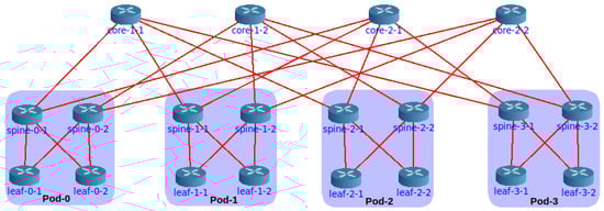
Figure 2.
A fat-tree with build in Core.
The Core Python API [63] can be used to scale the experiment and automate the configuration of the routing protocols. With this approach, the methodology is similar to that explained for Mininet, i.e., the topology and the configurations for experimentation follow a Python code. This code generates a fat-tree topology based on a given k, generates all the configurations for the routing protocol daemons (BGP, ISIS, Openfabric, or RIFT), and orchestrates the emulation, i.e., lunches all the processes, collects information or runs use cases, and eventually, stops the experiment.
4.4. Distributed Emulation
To outperform the emulation of a single host, we can distribute it into multiple hosts. Multiple factors can limit emulating large topologies in one host for different environments. For example, in Mininet, the host resources are limited when running multiple services on each node. Secondly, in Kathará, the limitation could also be given for the number of Docker containers per host.
After having a complete experiment built on top of Kathará, we can distribute the emulation across multiple nodes using Megalos since they share the same code base. However, they differ “only” in the virtualization manager (Kubernetes for Megalos).
Nevertheless, with the addition of Kubernetes to the environment, the orchestration of the experiment becomes more complex. First, Kubernetes imposes a configuration overhead. Indeed, setting up a Kubernetes cluster from scratch could be challenging depending on the cluster network layout. Furthermore, due to some design decisions and compatibility issues, there are a few differences between Kathará and Megalos when deploying a network scenario with Kubernetes. For example, when a routing daemon such as FRR is used, the eth0 network interface must be disabled inside the routing daemon because Kubernetes use each device eth0 interface for cluster management (check its deployment status, heartbeats, etc.). Second, some networking problems related to the distribution of the emulation and the creation of virtual interfaces appear. These problems are not clearly determined, and their nature lies in unexpected behaviors of Megalos (e.g., bugs). Kathará officially supports Kubernetes as a virtualization backend system as version 3.0.0, the one used in this research.
On the other hand, there are at least two options to distribute a Mininet emulation: Maxinet [64] and Distrinet [65]. Maxinet creates different Mininet instances in each physical node of the cluster and connects the vSwitches between different physical hosts with GRE tunnels. On the other hand, Distrinet, instead of using cgroups and network namespaces like Mininet, uses LXC containers and implements virtual links using VXLAN tunnels. Either environment could be used, but an extra configuration layer would be needed.
Finally, it is possible to distribute the emulation with Core. While the configuration steps to enable this feature are clear using the GUI, at the time of this writing, there is no documentation available on how to accomplish the distribution using a Python script.
4.5. A GUI-Based Emulation: GNS3
As a graphical network simulator, the topology must be built using the graphical interface. GNS3 provides by default some basic nodes, e.g., Virtual PC (VPC), Ethernet hub, Ethernet switch. To use layer three nodes, i.e., a router, an appliance must be provided. In this case, an appliance that provides an FRR router was installed. Figure 3 shows a basic fat tree built on GNS3. Unlike Mininet or Kathará, the configurations here cannot be automated in node startups. An option to configure the nodes with a routing protocol is to generate the configurations with an external script and inject it into each node. After that, GNS3 allows for saving the state of all the nodes, meaning that future experiments can start from a fat tree with full layer three connectivity. Although the FRR suite of protocols was selected (among other things because it supports BGP for the data center configuration), other appliances may be used, e.g., Cisco routers, Juniper routers, or OpenWrt [66] devices.
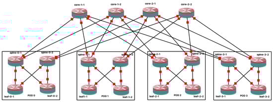
Figure 3.
A fat-tree build with GNS3.
Finally, GNS3 enables tshark by default to collect results, allowing for sniffing every link in the fabric. The GNS3 interface provides an input field for that option if live filtering is needed.
4.6. Analysis
The analysis methodology follows the flow shown in Figure 4. The first step is to configure the environments as described in the above sections. These configurations indicate to the simulated nodes the use of tshark, the interfaces to sniff in, and the filters to be applied during the capture of packets.
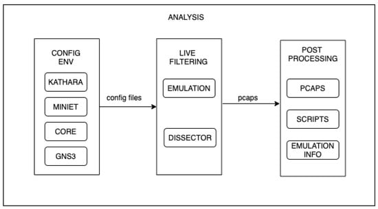
Figure 4.
Analysis flow.
After preparing the environment to collect results, the emulation can start. While the emulation is running, the analysis process has some tasks to take care of. The main task, of course, is to capture packets and save them in a pcap format. This task can be carried out in two ways: simply capturing all the traffic on every interface, or cleverly collecting the packets needed for the post-processing stage, which is called live filtering.
Live filtering is a crucial step in light of the scale that experiments may reach. Remember that there may be thousands of network nodes in a massive-scale data center, which translates into tens of thousands of interfaces to capture traffic (e.g., in a topology with 1280 nodes there are 40,960 interfaces). Without proper live filtering, every single capture can achieve a significant size. This adds two main drawbacks: (i) an additional storage requirement for the environments and (ii) an increase in the time required to carry out the post-processing step. The live filtering process faces these drawbacks using the dissectors provided by tshark for BGP, ISIS, and Openfabric. For the RIFT protocol, the dissector presented in [67] is used.
Finally, the post-processing is driven by a program that takes as input all the capture files (pcaps) and the information about the emulation and produces miscellaneous statistical output such as control packets per interface or the total number of BGP update packets.
4.7. Stop Criteria
Regardless of the environment, or the particular use case of interest, experimenting with routing protocols exhibits a peculiar challenge: determining when a protocol has converged. Tackling this problem is crucial to have accurate stop criteria for a set of use cases, e.g., checking the expected behavior of protocols at bootstrap or determining when a protocol has recovered from a failure.
This task can be undertaken in multiple ways, some dependent on the control messages of each protocol and others independent of the protocol. Of course, there is an intuitive way to solve the problem: wait long enough to be sure of protocol convergence. This might not be a problem for non-dense topologies or even fat trees with few nodes. However, if emulation of massive-scale data centers (eventually in a distributed environment) is to be performed, it is difficult to determine how long is enough.
Three ways to solve this problem have been explored: (i) pre-computing the routing tables of each node, (ii) feeding a stopping flag, and (iii) moving a sliding window. Due to the nature of an emulation, where a centralized program is responsible for starting and finishing the experiment, all these solutions are aware of a centralized entity. This entity, from now on the controller, comprises the knowledge of the entire topology, and it can send and receive messages from every emulated node.
4.7.1. Pre-Computed Tables
The first method to determine routing convergence is implemented by Algorithm 1, inspired by the Sibyl RT Calculator, part of the Sibyl framework available at [45].
This algorithm is presented from the controller side, i.e., the computations are centralized in the controller, which can interact with the nodes of the topology, e.g., requesting information.
Hence, the algorithm is quite simple: first, the controller, as an omniscient entity, pre-computes the forwarding tables of all the nodes of the topology (e.g., using an ECMP-aware Dijkstra algorithm) and secondly, requests the actual forwarding table to each node, comparing these tables with the expected ones. Notice that, with a decentralized approach, each node can compare the expected and actual tables and notify the controller only when they are equal.
A hybrid variation of this strategy may be implemented, where the controller pre-calculates the tables, notifies the nodes, and then waits for an “end message” of each node. Of course, when the controller is aware that every node has reached the expected table, the emulation must be finished under any approach.
| Algorithm 1 Convergence with pre-computed tables (centralized approach). |
| Require:
k: factor; T: Topology
Result: for ; do ▹ f could be Dijkstra end for while do end while |
Building a representative network graph is necessary to implement this stop criterion. It can be used to run a centralized multi-path routing algorithm (such as an ECMP-aware Dijkstra) to obtain every node’s expected forwarding tables. Python was chosen as the common programming language for all the environments, which allows the network to be abstracted from a graph using the NetworkX library [68]. This library also includes a function that calculates all the shortest paths between any source-destination pair. On the other hand, to get the actual forwarding tables, the emulation orchestrator must use the Python API provided by each emulator to query each node. Eventually, when all the pre-computed tables are equal to the actual tables, the orchestrator detects the routing protocol convergence and stops the emulation.
4.7.2. Stop Flag
This stop criterion depends on each specific routing protocol instead of the former. The main idea is to feed a flag that every control packet received (related to the protocol convergence).
Algorithm 2 abstracts the dependency of a protocol in a function called receivedControlPacket. This function must return the boolean True only when the node receives a control packet related to the convergence. These control packets vary depending on the protocol used as follows:
- BGP: the function must consider only UPDATES messages.
- RIFT: only TIE messages must be observed.
- Openfabric: the Link State PDU (LSP) are the messages considered here.
Note that the algorithm has a local view, i.e., the sequence followed by each topology node. It also has a pre-defined threshold, representing the maximum time willing to wait for another control packet. If no control packet arrives during this time, the node considers itself stabilized and notifies the controller. Observe that the effectiveness and efficiency of the heuristic depend on the value selected for the threshold.
| Algorithm 2 Convergence feeding a stop flag. |
| Require:t: threshold;
while flag do sleep(t) end while notifyEnd() |
4.7.3. Sliding Window
The sliding window concept here represents the idea of looping through a set of control packets with a fixed step size. Determining when a protocol has converged using sliding windows inherits some ideas from Algorithm 2.
First, it is also protocol-dependent, as shown by the usage of the function countRelevant in Algorithm 3. This function has the same considerations mentioned in Section 4.7.2 for the function receivedControlPacket, i.e., its behavior depends on the routing protocol being considered.
Second, the same threshold concept is used. In this case, it is the average of the control packets (related with convergence) over all the control packets received. Consequently, we set the minimum number of convergence-related control packets required in each window sample to determine convergence by defining this threshold.
Finally, with this approach, a node notifies the controller after its average number of control packets reaches the configured threshold.
| Algorithm 3: Convergence with sliding window. |
| Require:s: window size; t: threshold;
while do end while notifyEnd() |
5. Experimental Results
This section presents a thorough evaluation of the experimentation environments. Two main aspects were considered: validation, meaning that the environment correctly implements the fat-tree routing protocols, and scale, looking for the limits of each environment over the same underlying hardware.
Furthermore, the applicability of each environment is discussed, while a use case that goes beyond routing infrastructure is also presented: implementing a Layer 2 switching overlay over the routed fabric, needed for Virtual Machine migration, which is one of the most important use cases in data center management.
5.1. Validation
A complete fat-tree emulation program was developed for Mininet and Core. This program is capable of (i) generating any fat-tree with layer 3 configuration using the APIs provided by the emulators, (ii) generating the configuration files for the protocol daemons of BGP, ISIS, Openfabric, and rift-python, (iii) orchestrating the experiment, i.e., start the emulation and all the routing daemons needed, run test-cases, and finally stop the experiment (available at [69]). We use the Sybil framework mentioned above for Kathará and its distributed mode Megalos, also referred to in the repository, putting all the experimentation options together.
The base topology for the experimentation is a fat-tree, depicted in Figure 1. A common use case for all the environments was selected: the bootstrap case. This case aims to verify the expected behavior of the protocols at bootstrap, which permits verifying the correct convergence of the routing protocols configured in the fat tree. After the convergence of the protocols, there is full layer three multi-path connectivity between every pair of servers. This use case lays down a strong basis to build other use cases, e.g., a failure use case.
The single host emulations were run on a server with 30 CPUs and 126 GB of RAM. The bootstrap case was successfully performed over all the environments in the selected topology, validating the convergence of BGP, ISIS, Openfabric, and rift-python.
5.2. Scale
The scalability of the environments was tested using BGP, due to its industry-level implementation and scalability, which outperforms the rest of the routing protocols that were already analyzed under the Sybil framework. The single host emulations using Mininet, Kathará, and Core were tested over the infrastructure mentioned above. On the other hand, the distributed emulations were tested with Megalos using a cluster composed of 14 virtual machines with 4 CPUs and 16 GB de RAM each. Figure 5 shows the maximum k reached with each environment. Furthermore, Table 2 summarizes the results, adding the number of nodes and interfaces emulated with each environment.
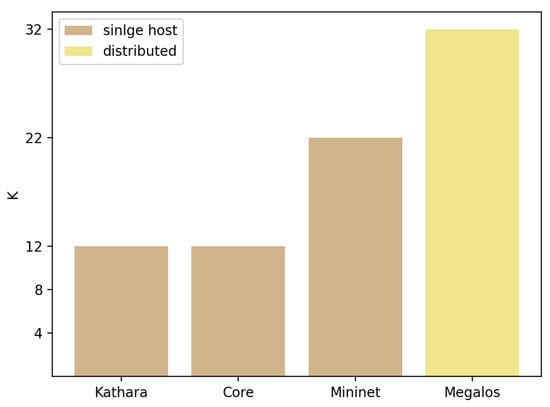
Figure 5.
Performance of environments as a function of k.
Table 2.
Scale results using BGP.
The first observation is that distributed emulation outperforms a single host one in terms of scalability. This is shown by the fact that Megalos successfully emulates more than a thousand nodes and forty thousand virtual interfaces. This result is expected since Megalos benefits from horizontal scalability, but there is a trade-off of scale vs. cost (i.e., the number of servers needed), which shall be considered. In contrast, on the single host side, Mininet scaled up to sixty hundred nodes and thirteen thousand virtual interfaces.
Considering only single host environments, Mininet outperforms Core and Kathará, emulating more than three times as many nodes and six times as many virtual interfaces. A feasible explanation for this performance gap of Core and Kathará is the density of the fat-tree topologies. Increasing the k factor rapidly increases the number of virtual interfaces and virtual links, exhausting host resources and preventing connectivity with the emulation process. On the other hand, increasing the k factor to 22 in Mininet leads to a 100% CPU use due to the topology density and the number of BGP and zebra daemons created.
5.3. Applicability
Each environment may be useful for different applications. On the one hand, the integrated set of tools for Kathará and Megalos (the aforementioned Sybil framework) permits deploying experiments promptly. Notably, in the case of Megalos, it allows benefiting of horizontal scalability over a Kubernetes cluster. On the other hand, Mininet is the right choice for single-host scalability, while Core provides a programmable emulation environment with GUI support. Finally, GNS3 is a suitable environment for teaching or demonstrating complex small-scale networking scenarios.
Table 3 shows the virtualization method used, the protocol suite deployed, and the recommended use for each environment.
Table 3.
Validation test over all the environments.
5.4. A Showcase: Switching Overlay in GNS3
Previous sections show that using GNS3 to emulate a fat-tree data center topology may not be the best option. Instead, we use programmable and scalable emulators such as Mininet or Kathará. Nonetheless, GNS3 may be very helpful to demonstrate small uses cases for teaching or training purposes.
In this sense, the reference fat tree was built in GNS3 using FRR routers. For simplicity, OSPF was used to provide multi-path layer 3 connectivity among all the nodes in the fabric. After that, VXLAN and EVPN were configured to have a transparent layer 2 (an important requirement presented in Section 2.6). Using this setup, the migrations of VMs among PODs in the fabric were successfully performed, keeping their IP addresses unchanged. This experiment is fully reproducible and available at [69].
6. Discussion and Conclusions
Experimental environments are necessary for developing and testing new networking protocols and services, and this is particularly true in the case of big, dense fat-tree topologies. Several experimental environments have been reviewed, developing specific utilities and configurations for this use case. The performed experiments followed two dimensions: (i) different routing protocols have been deployed and (ii) topology scalability as a function parameter k has been tested, as defined in Section 2.1.
Regarding routing protocols, all the tested implementations, namely BGP, IS-IS with flooding reduction, and RIFT-python, correctly implement ECMP routing. However, they differ in terms of scalability, BGP being the preeminent one, a result we obtained in our previous work over the Sybil framework [45].
Considering topology scalability, Mininet is the most scalable single-host emulation environment, with a maximum , while Megalos (being a distributed emulation environment) permits to scale the topology further up to . In this regard, there is room for further experimentation with distributed versions of Mininet. At the time of this writing, the needed tools for experiment automation were not implemented.
It is worth mentioning that the network, being a dynamic and “live” entity, is constantly exchanging routing messages. Nevertheless, there are often “calm” periods where the network has reached a stable state, usually noted as routing convergence. In this work, we designed heuristics to determine this stable state, as described in Section 4.7. These heuristics permit stopping experiments automatically, making it possible for experiments to last no longer than necessary, and correctly determining measurement marks for different metrics, such as routing updates count.
Overall, a suite of environments useful for different experimentation needs has been presented. These environments may accommodate to the available hardware, either a single host or a cluster. The review includes a comprehensive use case over GNS3, which is very useful for showing advanced capabilities at a small scale, ideal for teaching or training network operators.
As mentioned in the Introduction, once multi-path routing is in place, both forwarding and transport shall be considered in light of the statistical properties of the applications’ traffic. In this regard, there are specific data center applications, such as Map-Reduce, which produce the incast traffic pattern, among many other peculiarities. The existence of multiple data paths imposes difficulties for the classical TCP transport protocol and determines that nodes must implement particular forwarding policies. There is an important opportunity for research and experimentation considering these characteristics, and the presented environments permit exploring this research gap in a realistic and scalable fashion because, in addition to the control plane explored in this paper, they fully implement data plane capabilities in network nodes, but taken into account that performance measurements on the emulated environment are not comparable with real-world scenarios; to this end, a wise combination of emulation, simulation, and data science principles shall be explored.
Author Contributions
Conceptualization, L.A., A.C. and E.G.; methodology, L.A.; software, L.A.; formal analysis, L.A.; investigation, L.A.; writing—original draft preparation, L.A. and E.G.; writing—review and editing, L.A., A.C. and E.G.; visualization, L.A.; supervision, A.C. and E.G.; funding acquisition, L.A., A.C. and E.G. All authors have read and agreed to the published version of the manuscript.
Funding
This research was partially funded by the Uruguayan National Research and Innovation Agency (ANII) under Grant No. POS_NAC_M_2020_1_163847.
Institutional Review Board Statement
Not applicable.
Informed Consent Statement
Not applicable.
Data Availability Statement
Link to the git repository with emulators source code: https://gitlab.com/fing-mina/datacenters/fat-tree-emulators (accessed on 12 December 2021).
Acknowledgments
We would like to thank our colleagues from the Computer Networks research group at Università Roma Tre, Italy, for their contribution in developing the Sibyl framework.
Conflicts of Interest
The authors declare no conflict of interest.
References
- The Death of Transit?|APNIC Blog. Available online: https://blog.apnic.net/2016/10/28/the-death-of-transit/ (accessed on 12 December 2021).
- Cisco. Cisco Global Cloud Index: Forecast and Methodology, 2016–2021. White Paper. 2018. Available online: https://virtualization.network/Resources/Whitepapers/0b75cf2e-0c53-4891-918e-b542a5d364c5_white-paper-c11-738085.pdf (accessed on 12 December 2021).
- Clos, C. A study of non-blocking switching networks. Bell Syst. Tech. J. 1953, 32, 406–424. [Google Scholar] [CrossRef]
- Al-Fares, M.; Loukissas, A.; Vahdat, A. A Scalable, Commodity Data Center Network Architecture. In Proceedings of the ACM SIGCOMM 2008 Conference on Data Communication, Seattle, WA, USA, 17–22 August 2008; pp. 63–74. [Google Scholar] [CrossRef] [Green Version]
- Medhi, D.; Ramasamy, K. Network Routing, Second Edition: Algorithms, Protocols, and Architectures, 2nd ed.; Morgan Kaufmann Publishers Inc.: San Francisco, CA, USA, 2017. [Google Scholar]
- Bari, M.F.; Boutaba, R.; Esteves, R.; Granville, L.Z.; Podlesny, M.; Rabbani, M.G.; Zhang, Q.; Zhani, M.F. Data Center Network Virtualization: A Survey. IEEE Commun. Surv. Tutorials 2013, 15, 909–928. [Google Scholar] [CrossRef]
- Handley, M.; Raiciu, C.; Agache, A.; Voinescu, A.; Moore, A.W.; Antichi, G.; Wójcik, M. Re-Architecting Datacenter Networks and Stacks for Low Latency and High Performance. In Proceedings of the Conference of the ACM Special Interest Group on Data Communication, Los Angeles, CA, USA, 21–25 August 2017; pp. 29–42. [Google Scholar] [CrossRef] [Green Version]
- Lapukhov, P.; Premji, A.; Mitchell, J. Use of BGP for Routing in Large-Scale Data Centers. RFC 7938. RFC, Ed.; 2016. Available online: https://tools.ietf.org/html/rfc7938 (accessed on 12 December 2021).
- White, R.; Hegde, S.; Zandi, S. IS-IS Optimal Distributed Flooding for Dense Topologies. Internet-Draft Draft-White-Distoptflood-00, IETF Secretariat. 2020. Available online: https://datatracker.ietf.org/doc/html/draft-white-lsr-distoptflood-00 (accessed on 12 December 2021).
- Przygienda, T.; Sharma, A.; Thubert, P.; Rijsman, B.; Afanasiev, D. RIFT: Routing in Fat Trees. Internet-Draft Draft-Ietf-Rift-Rift-12, IETF Secretariat. 2020. Available online: https://datatracker.ietf.org/doc/html/draft-ietf-rift-rift-12 (accessed on 12 December 2021).
- Aelmans, M.; Vandezande, O.; Rijsman, B.; Head, J.; Graf, C.; Alberro, L.; Mali, H.; Steudler, O. Day One: Routing in Fat Trees (RIFT). Juniper Networks Books; USA. 2020. Available online: https://www.juniper.net/documentation/en_US/day-one-books/DO_RIFT.pdf (accessed on 12 December 2021).
- Patel, K.; Lindem, A.; Zandi, S.; Henderickx, W. BGP Link-State Shortest Path First (SPF) Routing. Internet-Draft Draft-Ietf-Lsvr-Bgp-Spf-13, IETF Secretariat. 2021. Available online: https://www.ietf.org/archive/id/draft-ietf-lsvr-bgp-spf-13.txt (accessed on 12 December 2021).
- Leiserson, C.E. Fat-trees: Universal networks for hardware-efficient supercomputing. IEEE Trans. Comput. 1985, C-34, 892–901. [Google Scholar] [CrossRef]
- Moy, J. OSPF Version 2; RFC 2328; IETF: Fremont, CA, USA, 1998. [Google Scholar]
- Shen, N.; Ginsberg, L.; Thyamagundalu, S. IS-IS Routing for Spine-Leaf Topology. Internet-Draft Draft-Shen-Isis-Spine-Leaf-Ext-07, IETF Secretariat. 2018. Available online: https://datatracker.ietf.org/doc/html/draft-shen-isis-spine-leaf-ext-07 (accessed on 12 December 2021).
- Martey, A.; Sturgess, S.; Martey, A. IS-IS Network Design Solutions. 2002. Available online: https://www.ciscopress.com/store/is-is-network-design-solutions-9781578702206 (accessed on 12 December 2021).
- Zandi, S. LinkedIn OpenFabric Project. 2017. Available online: https://www.slideshare.net/shawnzandi/linkedin-openfabric-project-interop-2017 (accessed on 12 December 2021).
- Rekhter, Y.; Li, T.; Hares, S. A Border Gateway Protocol 4 (BGP-4). RFC 4271, RFC Editor. 2006. Available online: http://www.rfc-editor.org/rfc/rfc4271.txt (accessed on 12 December 2021).
- Vohra, Q.; Chen, E. BGP Support for Four-Octet AS Number Space. RFC 4893. RFC, Ed.; 2007. Available online: https://datatracker.ietf.org/doc/html/rfc4893 (accessed on 12 December 2021).
- Oliveira, R.; Zhang, B.; Pei, D.; Zhang, L. Quantifying Path Exploration in the Internet. IEEE/ACM Trans. Netw. 2009, 17, 445–458. [Google Scholar] [CrossRef]
- Dutt, D.G. BGP in the Data Center; O’Reilly: Newton, MA, USA, 2017. [Google Scholar]
- Ginsberg, L.; Previdi, S.; Wu, Q.; Tantsura, J.; Filsfils, C. BGP—Link State (BGP-LS) Advertisement of IGP Traffic Engineering Performance Metric Extensions. RFC 8571. RFC, Ed.; 2019. Available online: https://datatracker.ietf.org/doc/html/rfc8571 (accessed on 12 December 2021).
- Mahalingam, M.; Dutt, D.; Duda, K.; Agarwal, P.; Kreeger, L.; Sridhar, T.; Bursell, M.; Wright, C. Virtual eXtensible Local Area Network (VXLAN): A Framework for Overlaying Virtualized Layer 2 Networks over Layer 3 Networks; RFC 7348; IETF: Fremont, CA, USA, 2014. [Google Scholar]
- Sajassi, A.; Drake, J.; Bitar, N.; Shekhar, R.; Uttaro, J.; Henderickx, W. A Network Virtualization Overlay Solution Using Ethernet VPN (EVPN); RFC 8365; IETF: Fremont, CA, USA, 2018. [Google Scholar]
- Roman. Nokia SR Linux Goes Public. 2021. Available online: https://netdevops.me/2021/nokia-sr-linux-goes-public/ (accessed on 12 December 2021).
- Cisco. NetDevOps-Cisco DevNet. 2021. Available online: https://developer.cisco.com/netdevops/ (accessed on 12 December 2021).
- Maor, I. Make a Digital Twin of Your Data Center. 2021. Available online: https://developer.nvidia.com/blog/make-a-digital-twin-of-your-data-center-with-sonic-running-on-nvidia-air/ (accessed on 12 December 2021).
- Liu, H.; Zhu, Y.; Padhye, J.; Cao, J.; Tallapragada, S.; Lopes, N.; Rybalchenko, A.; Lu, G.; Yuan, L. CrystalNet: Faithfully Emulating Large Production Networks. In Proceedings of the 26th Symposium on Operating Systems Principles, Shanghai, China, 28–31 October 2017; pp. 599–613. [Google Scholar]
- Hong, H.; Wu, Q.; Dong, F.; Song, W.; Sun, R.; Han, T.; Zhou, C.; Yang, H. NetGraph: An Intelligent Operated Digital Twin Platform for Data Center Networks. In Proceedings of the ACM SIGCOMM 2021 Workshop on Network-Application Integration, Virtual, 23 August 2021; pp. 26–32. [Google Scholar] [CrossRef]
- Li, Y.; Yin, X.; Wang, Z.; Yao, J.; Shi, X.; Wu, J.; Zhang, H.; Wang, Q. A Survey on Network Verification and Testing With Formal Methods: Approaches and Challenges. IEEE Commun. Surv. Tutor. 2019, 21, 940–969. [Google Scholar] [CrossRef]
- Meza, J.; Xu, T.; Veeraraghavan, K.; Mutlu, O. A Large Scale Study of Data Center Network Reliability. In Proceedings of the Internet Measurement Conference 2018, Boston, MA, USA, 31 October–2 November 2018; pp. 393–407. [Google Scholar] [CrossRef] [Green Version]
- Nsnam. ns-3 a Discrete-Event Network Simulator for Internet Systems. 2021. Available online: https://www.nsnam.org/ (accessed on 12 December 2021).
- OpenSim Ltd. OMNeT++ - Discrete Event Simulator. 2021. Available online: https://omnetpp.org/ (accessed on 12 December 2021).
- FRRouting. FRRouting. 2021. Available online: https://frrouting.org/ (accessed on 12 December 2021).
- Muelas, D.; Ramos, J.; Vergara, J.E.L.d. Assessing the Limits of Mininet-Based Environments for Network Experimentation. IEEE Netw. 2018, 32, 168–176. [Google Scholar] [CrossRef]
- Pediaditakis, D.; Rotsos, C.; Moore, A.W. Faithful reproduction of network experiments. In Proceedings of the 2014 ACM/IEEE Symposium on Architectures for Networking and Communications Systems (ANCS), Marina del Rey, CA, USA, 20–21 October 2014; pp. 41–52. [Google Scholar]
- Bonofiglio, G.; Iovinella, V.; Lospoto, G.; Di Battista, G. Kathará: A container-based framework for implementing network function virtualization and software defined networks. In Proceedings of the NOMS 2018—2018 IEEE/IFIP Network Operations and Management Symposium, Taipei, Taiwan, 23–27 April 2018; pp. 1–9. [Google Scholar] [CrossRef]
- Scazzariello, M.; Ariemma, L.; Caiazzi, T. Kathará: A Lightweight Network Emulation System. In Proceedings of the NOMS 2020—2020 IEEE/IFIP Network Operations and Management Symposium, Budapest, Hungary, 20–24 April 2020; pp. 1–2. [Google Scholar] [CrossRef]
- Merkel, D. Docker: Lightweight linux containers for consistent development and deployment. Linux J. 2014, 2014, 2. [Google Scholar]
- Quagga. Quagga Routing Suite. 2021. Available online: https://www.quagga.net/ (accessed on 12 December 2021).
- Lumbis, P. FRR: The Most Popular Network Router You’ve Never Heard of. 2021. Available online: https://www.nextplatform.com/2020/10/26/frr-the-most-popular-network-router-youve-never-heard-of/ (accessed on 12 December 2021).
- Kathará. Kathará. 2021. Available online: https://github.com/KatharaFramework/Kathara (accessed on 12 December 2021).
- Kubernetes. Kubernetes. 2021. Available online: https://kubernetes.io/ (accessed on 12 December 2021).
- Scazzariello, M.; Ariemma, L.; Battista, G.D.; Patrignani, M. Megalos: A Scalable Architecture for the Virtualization of Network Scenarios. In Proceedings of the NOMS 2020—2020 IEEE/IFIP Network Operations and Management Symposium, Budapest, Hungary, 20–24 April 2020; pp. 1–7. [Google Scholar] [CrossRef]
- Caiazzi, T.; Scazzariello, M.; Alberro, L.; Ariemma, L.; Castro, A.; Grampin, E.; Battista, G.D. Sibyl: A Framework for Evaluating the Implementation of Routing Protocols in Fat-Trees. 2021. Available online: https://gitlab.com/uniroma3/compunet/networks/sibyl-framework/sibyl (accessed on 12 December 2021).
- Caiazzi, T.; Scazzariello, M.; Ariemma, L. VFTGen: A Tool to Perform Experiments in Virtual Fat Tree Topologies. In Proceedings of the IM 2021—2021 IFIP/IEEE International Symposium on Integrated Network Management, Bordeaux, France, 17–21 May 2021; pp. 1–2. [Google Scholar]
- Lantz, B.; Heller, B.; McKeown, N. A Network in a Laptop: Rapid Prototyping for Software-Defined Networks. In Proceedings of the 9th ACM SIGCOMM Workshop on Hot Topics in Networks, Monterey, CA, USA, 20–21 October 2010. [Google Scholar] [CrossRef]
- Team, M. Mininet an Instant Virtual Network on Your Laptop (or Other PC). 2018. Available online: http://mininet.org/ (accessed on 12 December 2021).
- Ruslan, R.; Othman, N.B.; Fuzi, M.M.; Ghazali, N. Scalability Analysis in Mininet on Software Defined Network using ONOS. In Proceedings of the 2020 Emerging Technology in Computing, Communication and Electronics (ETCCE), Dhaka, Bangladesh, 21–22 December 2020; pp. 1–6. [Google Scholar] [CrossRef]
- Open Networking Foundation. Open Network Operating System (ONOS). 2021. Available online: https://opennetworking.org/onos/ (accessed on 12 December 2021).
- Ahrenholz, J.; Danilov, C.; Henderson, T.R.; Kim, J.H. CORE: A real-time network emulator. In Proceedings of the MILCOM 2008—2008 IEEE Military Communications Conference, San Diego, CA, USA, 16–19 November 2008; pp. 1–7. [Google Scholar] [CrossRef]
- Ahrenholz, J. Comparison of CORE network emulation platforms. In Proceedings of the MILCOM 2010 Military Communications Conference, San Jose, CA, USA, 31 October–3 November 2010; pp. 166–171. [Google Scholar] [CrossRef]
- Technologies, G. GNS3: The Software That Empowers Network Professionals. 2021. Available online: https://www.gns3.com/ (accessed on 12 December 2021).
- Orebaugh, A.; Ramirez, G.; Beale, J.; Wright, J. Wireshark & Ethereal Network Protocol Analyzer Toolkit; Syngress Publishing: Rockland, MA, USA, 2007. [Google Scholar]
- Tcpdump. Tcpdump. 2021. Available online: https://www.tcpdump.org/ (accessed on 12 December 2021).
- Wireshark. TSHARK Manual Page. 2021. Available online: https://www.wireshark.org/docs/man-pages/tshark.html (accessed on 12 December 2021).
- KimiNewt. Pyshark. 2021. Available online: https://github.com/KimiNewt/pyshark (accessed on 12 December 2021).
- Sikos, L.F. Packet analysis for network forensics: A comprehensive survey. Forensic Sci. Int. Digit. Investig. 2020, 32, 200892. [Google Scholar] [CrossRef]
- Chapman, C. (Ed.) Chapter 7—Using Wireshark and TCP dump to visualize traffic. In Network Performance and Security; Syngress: Boston, MA, USA, 2016; pp. 195–225. [Google Scholar] [CrossRef]
- Rijsman, B. Routing in Fat Trees (RIFT). 2021. Available online: https://github.com/brunorijsman/rift-python (accessed on 12 December 2021).
- Panandr. Mininet-Fattree. 2016. Available online: https://github.com/panandr/mininet-fattree (accessed on 12 December 2021).
- Mininet. Mininet Python API Reference Manual. 2021. Available online: http://mininet.org/api/annotated (accessed on 12 December 2021).
- Common Open Research Emulator. Python API. 2021. Available online: http://coreemu.github.io/core/python (accessed on 12 December 2021).
- Wette, P.; Dräxler, M.; Schwabe, A.; Wallaschek, F.; Zahraee, M.H.; Karl, H. MaxiNet: Distributed emulation of software-defined networks. In Proceedings of the 2014 IFIP Networking Conference, Trondheim, Norway, 2–4 June 2014; pp. 1–9. [Google Scholar] [CrossRef]
- Di Lena, G.; Tomassilli, A.; Saucez, D.; Giroire, F.; Turletti, T.; Lac, C. Distrinet: A mininet implementation for the cloud. Comput. Commun. Rev. 2021, 51, 3–9. [Google Scholar] [CrossRef]
- OpenWrt Project. OpenWrt Project. 2021. Available online: https://openwrt.org/ (accessed on 12 December 2021).
- Lucero, M.; Parnizari, A.; Alberro, L.; Castro, A.; Grampín, E. Routing in Fat Trees: A protocol analyzer for debugging and experimentation. In Proceedings of the 2021 IFIP/IEEE International Symposium on Integrated Network Management (IM), Bordeaux, France, 17–21 May 2021; pp. 788–792. [Google Scholar]
- NetworkX. NetworkX. 2021. Available online: https://networkx.org/ (accessed on 12 December 2021).
- Alberro, L. Experimentation Environments for Routing Protocols in the Datacenter. 2021. Available online: https://gitlab.com/fing-mina/datacenters/fat-tree-emulators (accessed on 12 December 2021).
Publisher’s Note: MDPI stays neutral with regard to jurisdictional claims in published maps and institutional affiliations. |
© 2022 by the authors. Licensee MDPI, Basel, Switzerland. This article is an open access article distributed under the terms and conditions of the Creative Commons Attribution (CC BY) license (https://creativecommons.org/licenses/by/4.0/).