1. Introduction
Thanks to the 4th Industrial Revolution, Internet of Things (IoT) technology is expanding and prospering in many industrial sectors. As a result, a growing number of domestic and foreign companies are rushing to launch their own IoT platforms for the launch of new services. Currently, the data computing and storage processes are mainly done in the central cloud on the IoT platform [
1]. The centralized IoT system, however, is causing many problems. It requires a huge central server that processes and stores data received from a number of devices This requires large administrative costs. Therefore, it wants to improve efficiency by utilizing IoT technology. Continuing to increase access to IoT devices is difficult because there is a limitation at the central server [
2]. While central servers need to be expanded to address this problem, it is highly inefficient and it is not recommended to expand a central server that already has high-performance. In addition, IoT devices require efficient management of data and the role of the central server is very important because of real-time data processing. Therefore, if there is a problem with the central server, all IoT devices will be useless. To address these problems, distributed networking of IoT is expected in the future [
3,
4,
5]. In this case, the central server’s role will be reduced, and the portion of the work handled by the terminal device will increase. In the future era of IoT, firmware-based IoT devices, which only deal with simple tasks, will be raised to the level of the RTOS (Real Time Operation System) to secure safety and connectivity. We enhanced our parcel delivery system based on existing IoT platform provided by the SK Telecom (SKT) of Republic of Korea (Seoul, Korea). In addition, we implemented simple end-to-end IoT systems by using a centralized IoT System. The name of the IoT platform is ThingPlug which also provides LoRaWAN as a dedicated global network for IoT. In this paper, we propose an efficient parcel delivery system with IoT devices.
Currently, the Parcel Delivery System consists of the Hub and Spoke method [
6,
7,
8,
9,
10]. The Hub and Spoke method is constructed assuming a large amount of Parcel is delivered. The method has the advantage of being able to transport efficiently in many areas with a small hub, but it also has the problem of having to visit the hub on adjacent streets. The Point to Point System used in aviation systems connects Point and Point as much as necessary to facilitate use. We aim to make a new Parcel Delivery System by adding an IoT Device from the current Hub and Spoke method [
11].
Section 2 introduces related technologies in order to fulfill our purpose.
Section 3 shows the design of our parcel delivery system.
Section 4 describes our IoT device hardware design.
Section 5 explains the process of connections between IoT devices and a distributed network IoT platform.
Section 6 discusses technical issues to be solved for our IoT applications.
Section 7 provides conclusions and mentions the future research.
2. Background: Underlying IoT Technology
To implement IoT services, various elements such as devices, networks, application servers, and modules are needed. There is a service called IoT platform that helps to use these devices efficiently [
12]. IoT platform refers to services that can meet various components and easily combine and increase utility value by connecting each element. Typically, Qualcomm’s AllJoyn, Microsoft’s Azure IoT Suite, and SKT’s ThingPlug offer centralized services [
13,
14]. There are so many IoT connection protocols such as Sigox, LoRa, LTE-M, NB-IoT, Cat-M1 [
15], and so on. Although it can be used up, SKT’s ThingPlug is used as an IoT platform in this paper. ThingPlug supports Lora, Cat-M1, LTE-M, and LTE. Geopositioning data are low-capacity data and real-time is not strictly required. Thus, we found low speed and power efficient communication and it was LoRa [
16,
17].
2.1. LoRa Technology
LoRa is a technology that is actively being developed and distributed around the world, mainly around the LoRa Alliance. Unlike conventional smartphone networks such as 3G and LTE, the technology is capable of communicating at low power and over 10 km at a minimum power consumption. They do not need separate base stations or relaying equipment, can send and receive data directly, and have low building costs and high scalability. Although it does not show a high data rate, it is specialized for certain periodic data transmission rather than real-time data, enabling long-distance communication with low power. Existing low-power wireless communication protocols such as Bluetooth and Zigbee exist, but the scope of communication is short and the cost of building infrastructure to extend the scope of communication is additional. However, LoRa technology can solve problems very simply. In the security field, which has recently become a hot topic in IoT, LoRa adapts AES128 to security. That is, by using LoRa, telecommunications services can be provided with mobility, localization and security.
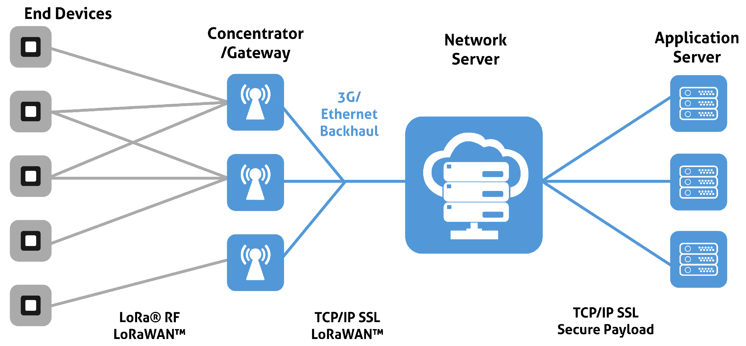
2.2. ThingPlug Structure
The designed terminal device collects sensor data according to our purposes and sends it to the ThingPlug network server through the gateway. Application Servers can import data stored on the ThingPlug Network server and send control commands to the terminal device. These sequences are well expressed in
Figure 1.
2.3. ThingPlug Usage
There are three ways to leverage a ThingPlug Network Server. The first case is to use one terminal device. In this case, we can communicate with a ThingPlug Network Server using API provided or with ThingPlug via a LoRa module. The second case is to use the terminal devices near the fixed gateway. In this case, the wireless start topology method allows you to connect the terminal device with the gateway. The gateway then collects the sensors from the terminal device and transmits them to the ThingPlug server. At this time, wireless communication between the terminal and gateway can then use LoRa RF, and communication between the gateway and ThingPlug can use Ethernet. The third case is the terminal device that moves a wide area. In this case, it is not possible to cover all terminal devices in which one gateway is moving extensively. Therefore, we use a Low Power Wide Area Network (LPWAN) that can communicate with a ThingPlug server anywhere. LPWANs include LoRaWAN and Sigfox [
18,
19,
20].
2.4. Related Works
In the past, the Logistic Hub method was adopted as a method of optimizing the Parcel System, and the focus on the hub was placed on the research. By improving logistics movement, logistic hub location can be optimized by identifying logistics movement patterns [
8,
9,
10]. Different circumstances may be applied to change the hub’s position [
21]. In addition, it is striving to establish a platform by applying IoT to logistics, research robots, and IoT-based intelligent transport systems [
22]. In the logistics sector, however, the government is studying new logistics methods using drones instead of improving existing logistics methods [
23,
24]. To our knowledge, there has been no research yet to combine IoT with Parcel Delivery System to enhance the efficiency of the moving path.
3. Improved Parcel Delivery System Design
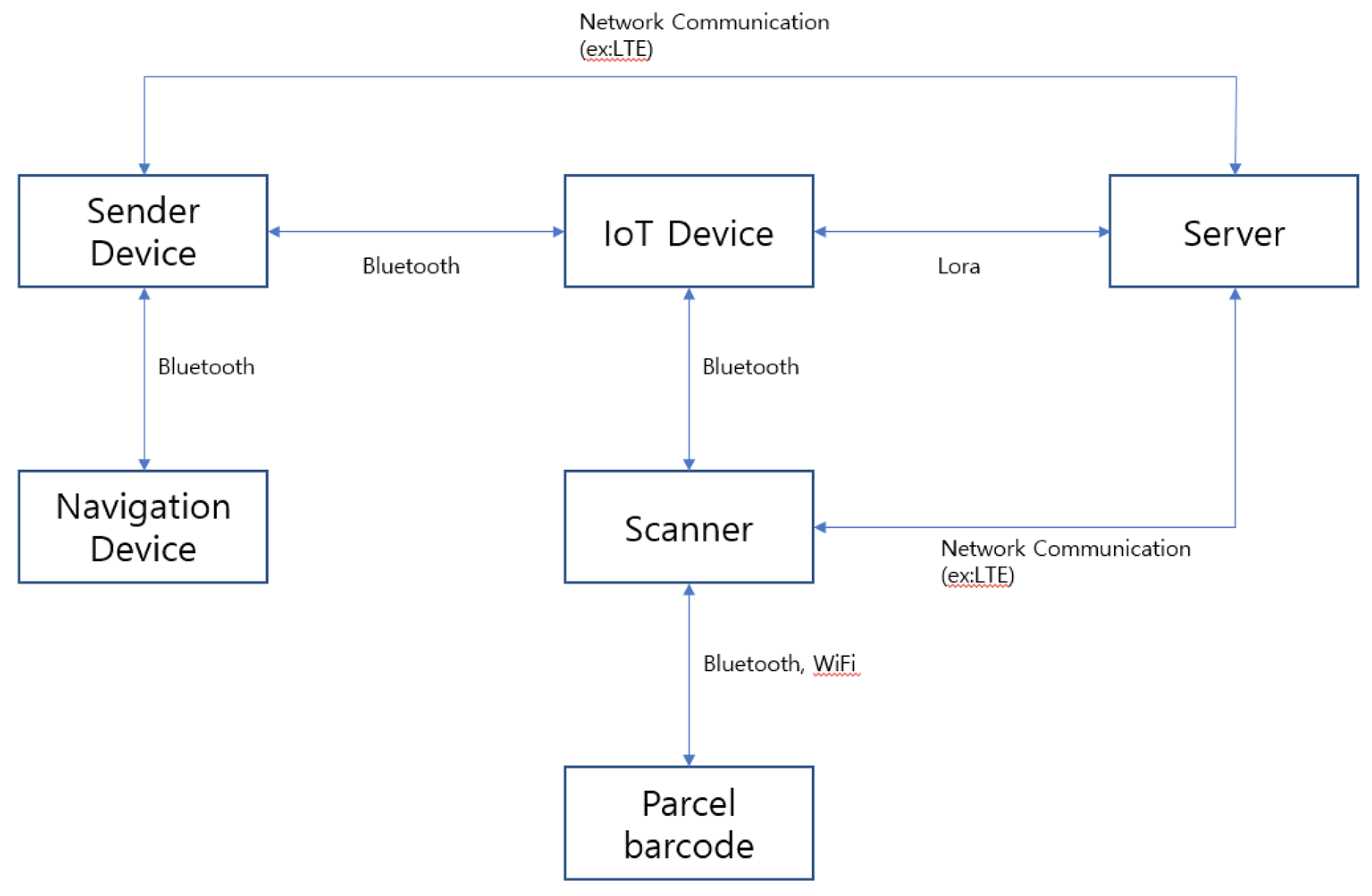
The method of operation of IoT devices attached to parcel boxes has been divided into several stages. There are four steps: the collection phase, the GPS phase, the moving phase, and the completion phase. The technology used by
Figure 2 allows you to identify the process of data exchange. Since IoT devices, transmitter devices, and navigation devices are each nearby, they are connected by NFC technology, especially Bluetooth. The server is connected to the Sender Device, IoT Device, and Scanner. In addition, IoT devices will be connected to the sending device and scanner, while IoT devices and navigation devices will be connected through the sending device. The scanner reads information from the Barcode and delivers it to IoT devices, and if the IoT devices and servers are not connected, the Scanner and Server are connected. A sequence diagram of applying an intermediate delivery algorithm to an existing parcel delivery system is shown in
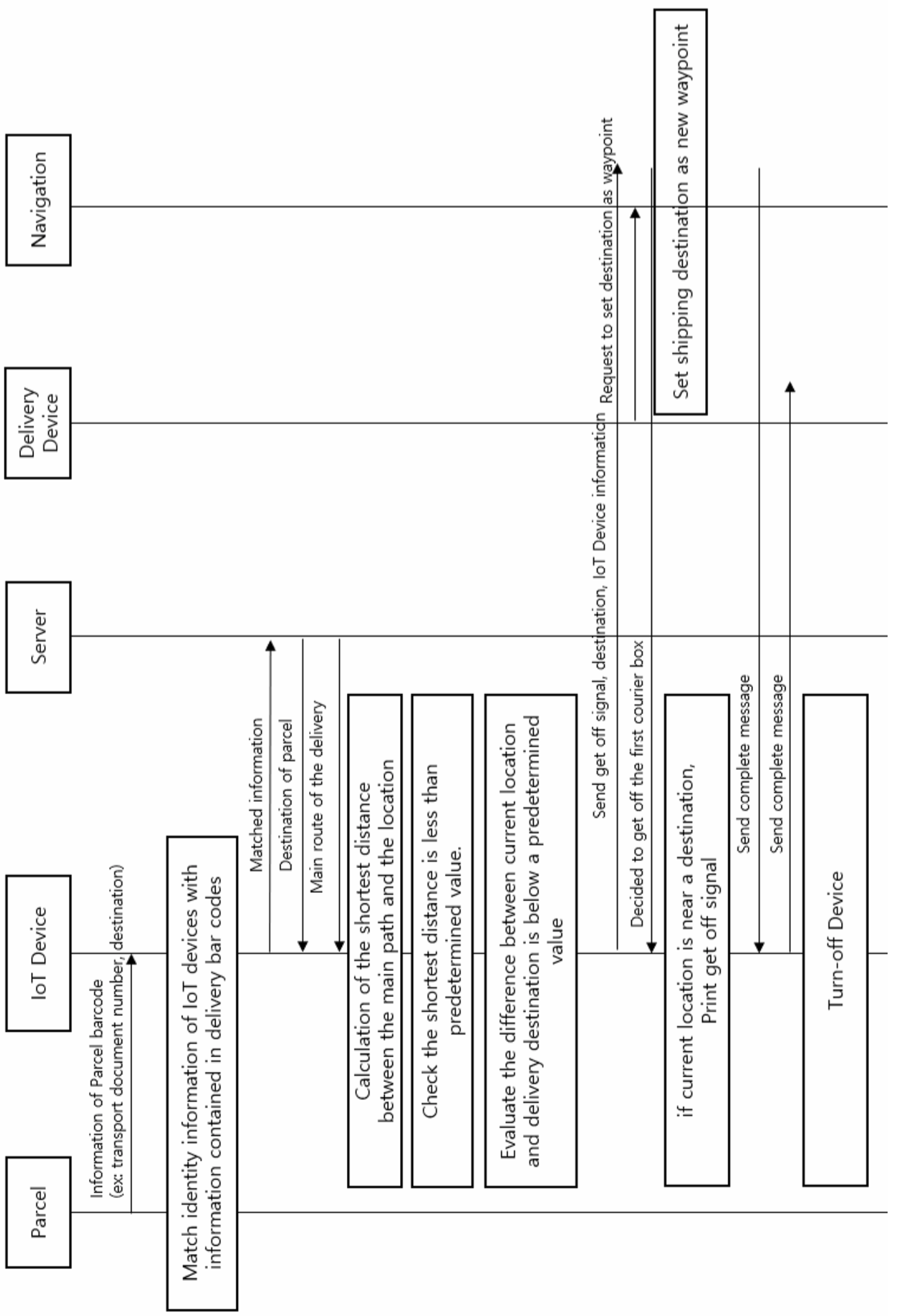
Figure 3. It presents an Improved Parcel Delivery system with a centralized IoT platform. Device stores and sends geopositioning information to the server periodically. The server calculates distance of destination and route, and notifies the courier if there is a courier that can be disembarked.
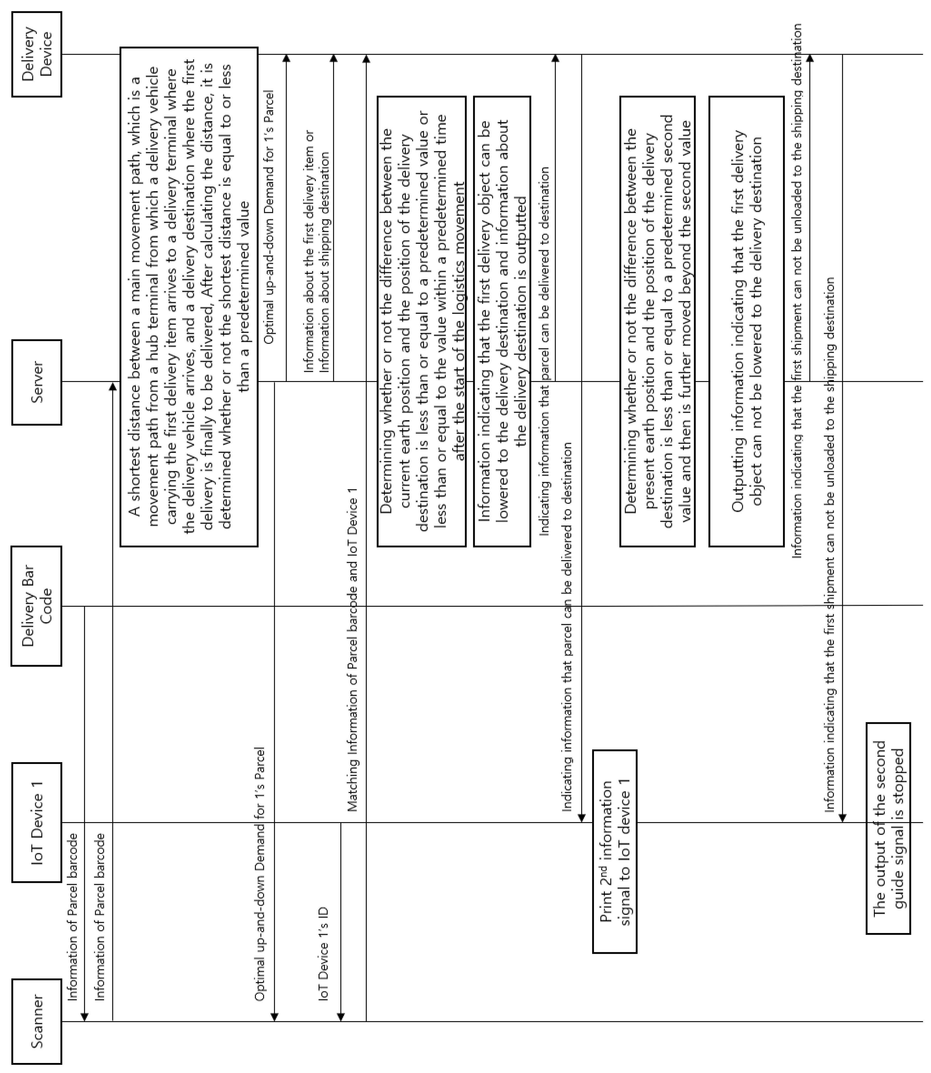
Figure 4 is a Sequence diagram that applies IoT devices and an intermediate landing algorithm. It presents an improved Parcel Delivery system with a centralized end-to-end IoT platform. The IoT device calculates the distance between the current location and destination instead server. Only the resulting data are stored on the server. In other words, data are generated from IoT devices, transmitted to ThingPlug via Lora, and data are computed and stored in ThingPlug. At this time, the IoT device operates according to the condition, and transferred the result to ThingPlug via Lora.
3.1. Parcel Collection Stage
When a parcel pick-up starts with a shipping box attached to IoT devices and IoT devices are turned on, ID information is printed through display modules. In a moment, LoRa will be connected to the server. The scanner then collects data from the barcode attached to the shipping box. Information of IoT devices, invoice number, and delivery location are matched to send to the server and stored in table form. The IoT device calculates the shortest route to collect and parcel destination. If that distance is less than threshold value, then add destination as a waypoint.
3.2. GPS Data Collection Stage
When data are received from the GPS module of the IoT device, data about the current location of the IoT device are stored. If data cannot be received from the GPS module, the following steps are required. First, you should get a nearby access point (AP) with a Wi-Fi module. Then, obtain the current location information from the MAC address and API of AP [
25]. If the Wi-Fi AP is not accessible, it receives the current location information from the Bluetooth module attached to the IoT device of the courier smartphone. If you don’t get location information, you have to wait for a specific delay and start all over again. This algorithm is shown in the Algorithm 1.
| Algorithm 1 Getting location data en route |
Input: NULL Output: Geopositioning Data - 1:
if GPS.available() then - 2:
return Get.GPS_data(); - 3:
else - 4:
if WiFi.available then - 5:
return Get.WiFi_Data(); - 6:
else - 7:
Connect_Bluetooth() - 8:
return Get.Data_From_Bluetooth(); - 9:
end if - 10:
delay(default_time)
|
3.3. Shortest Path Check Stage
At this stage, we should know how to identify the shortest route to add a new destination. At the destination, other parcels can simply stop and move to the next logistics hub. The process is as follows. First, get GPS data from stage
Section 3.2. It then calculates the distance between the current GPS data and the destination. In case the distance is shorter than the threshold value, then send the parcel data to the ThingPlug server via LoRa and send ID info of an IoT device to a transmitter’s smartphone via Bluetooth. Then, add new destination information on the IoT device and update the logistics route. Finally, complete the moving step and move onto stage
Section 3.4. If the distance is longer than the threshold value, wait for a certain time delay before the loop restarts.
3.4. Parcel Delivery Completion Stage
After the stage
Section 3.3 checks the distance between the current location and destination every fixed time, if the distance value is very small, the IoT device will recognize that the parcel has arrived at its destination. The IoT device will send a signal by courier. Then, the courier can recognize that the box must be lowered. In addition, the IoT device sends the completion signal to the ThingPlug server to update the signal. The server will then send a completion message to the IoT device. The IoT device will emit a return signal and will be turned off. From then, the courier will collect IoT devices.
3.5. IoT Device Functionalities
To perform these functions, the IoT device performs the following functions for each stage.
Get geopositioning data from the GPS module
Get geopositioning data from the Wi-Fi module
Get geopositioning data from the Bluetooth module.
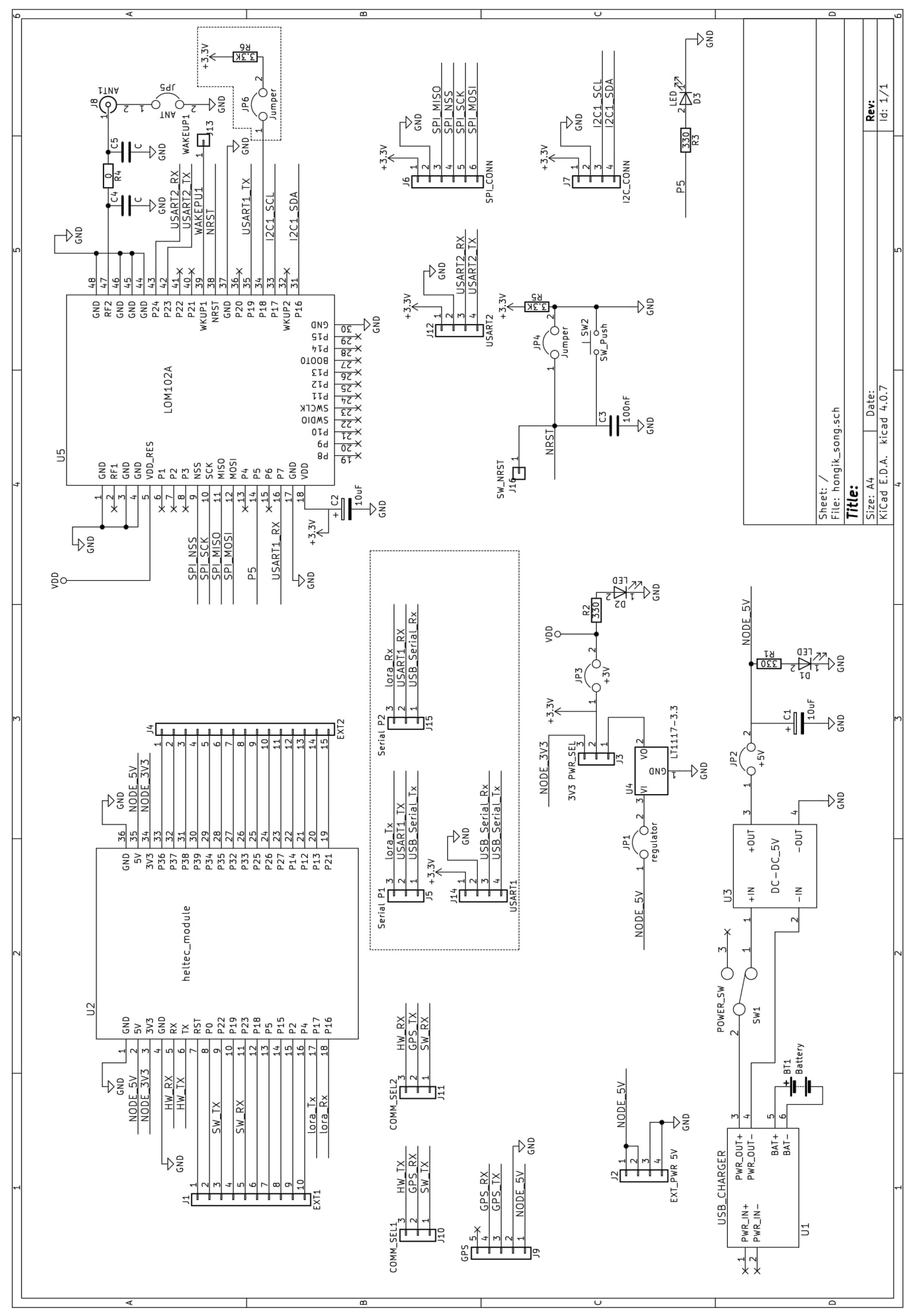
4. IoT Device Hardware Design
To utilize all the functions designed in
Section 3, we need MCU, LoRa module, GPS module, Wi-Fi module, and Bluetooth module. They also needed an antenna for reliable connection with the LoRa network, Battery, and Charging module to supply power. Thus, we used Heltec MCU including Wi-Fi and Bluetooth, LOM102A LoRa module of SEONG JI INDUSTRIAL and NEO-6M GPS module. We also wanted to increase portability with a lithium polymer battery. The Schematic Diagram of our IoT device in order to implement IoT device functionalities aforementioned is shown in
Figure 5.
4.1. MCU: Heltec Module
We found the most commensurate MCU for use LoRa, Wi-Fi, and GPS function [
26]. We chose an ESP32 based Heltec MCU board with LoRa, Wi-Fi function, and Bluetooth function. This module includes a LoRa function, but it cannot be used because it is different from the standard for use in Korea. In addition, the module includes the LoRa function, and we judge that it can control LoRa easily. In order to centrally control, MCU communicated LoRa by RX/TX, SPI, and I2C method. To connect external devices, we used Bluetooth and Wi-Fi functions, and the control GPS module to obtain data to be sent to LoRa.
We used an UART communication method to use LoRa and GPS modules. However, there are two pairs of RX, TX pins for UART communication on pin diagrams. We used one pair of RX, TX to use LoRa. In addition, we need two pairs of RX, TX pins for safe connection with GPS modules. Therefore, we need to change the GPIO port for an additional UART pin. First, we checked a pin diagram to use a not specified pin. In addition, we use the open source of a third party to change GPIO to UART. We can check the detailed specifications of the board here [
27].
4.2. LoRa Module
We adapt the LoRa module as LOM102A of SEONG JI INDUSTRIAL. An antenna has been added to communicate safely to the server while using the module. At first, to use LoRa, it is necessary to modify the firmware. Modifications to the firmware require direct access without going through the MCU. Thus, we designed the pin to direct access. SPI and I2C connection work was completed to be used in case of serial communication error with MCU. In addition, since it is necessary to reset the LoRa remotely, we designed an additional pin connection so that the reset command can be transferred from the MCU. We can check the detailed specifications of the board here [
28].
4.3. GPS Module and Battery
We added GPS module, antenna, Battery, Charging module, and switch. The GPS module is attached to get geopositioning data and an antenna helps with getting more accurate data. Power can be supplied through the MCU connected to the outside, but it is impossible on the go. Battery allows the device to operate on the go. The charging module helps to reuse battery. When IoT device is not in use, the module can be switched on and off using the ON-OFF switch. We can check the detailed specifications of the board here [
29].
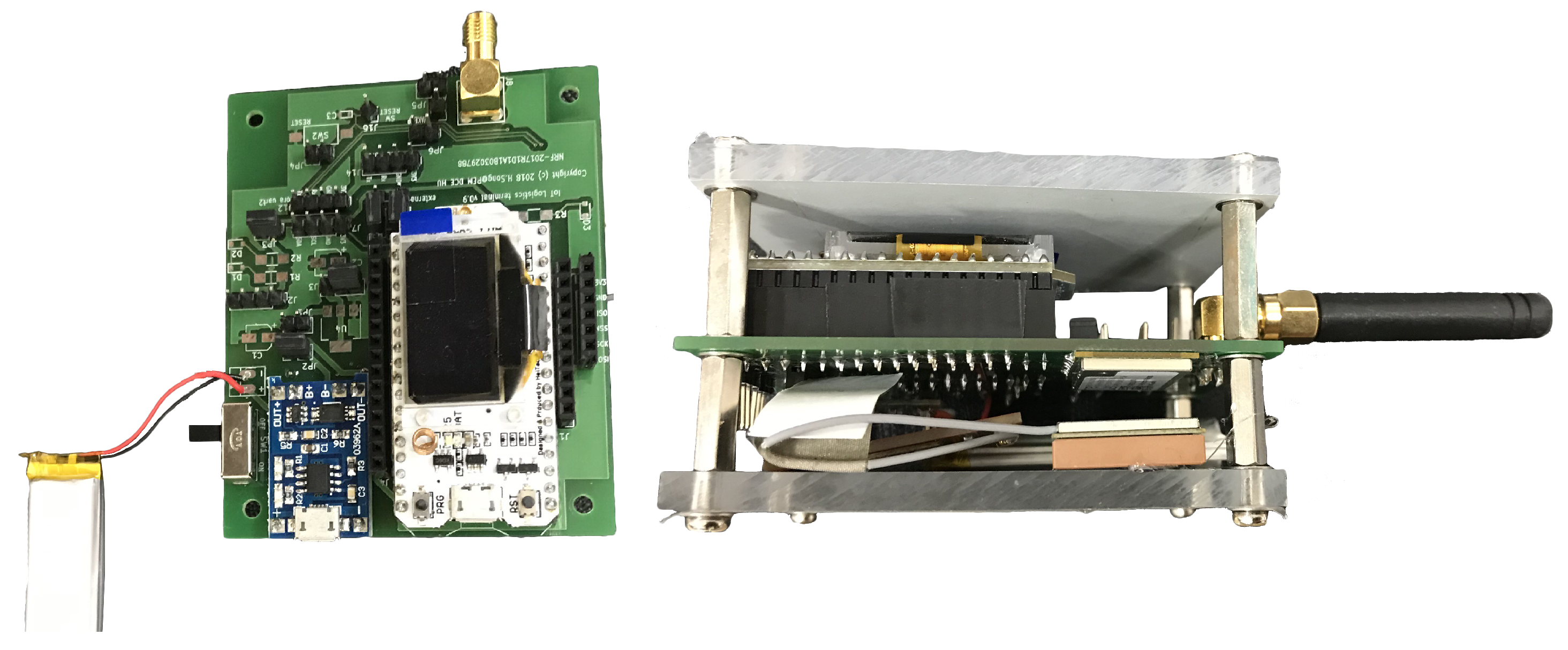
4.4. IoT Device Prototype
We implemented an IoT Device for a parcel delivery system as shown in
Figure 6. To control this device, the MCU board with a built-in ESP32-based Wi-Fi and Bluetooth function, GPS module for GPS tracking function, battery, and battery charging are attached. The purpose of the design was to make the device as small as possible when manufacturing the device, and, to prepare for the impact between delivery and delivery, the impact absorbing rubber was attached to the upper and lower parts of the IoT device, and acrylic plates and devices were firmly fixed using brass supports. To prevent impact damage to the acrylic or PCB plates, washers were added to each joint to enhance stability. In addition, the antenna was attached for desired LoRa communication. The battery, which is at greater risk of short-circuiting due to the weight during delivery, was fixed on acrylic plates. The GPS Sensor was secured on acrylic plates to enable stable sensor reception. After checking whether the battery functions properly during delivery, we confirmed that 80 h of continuous operation is practically possible. Although it has been suggested that the protruding part of the antenna will be a problem when using the IoT device seal, it is actually attached directly to the parcel when collecting data and can be used reliably when attaching it toward the sky when attached.
5. IoT Platform Interlocking Process
In this paper, we adopted SKT’s IoT platform, ThingPlug, which utilizes LoRaWAN installed in South Korea, considering the size of the data and the size of the commercial network transmitted by the IoT device. SKT provides commercial network linkage through its officially certified LoRa module. In this paper, the LoRa module of SEONG JI INDUSTRIAL was used. The LoRa module is connected to the Micro Controller Unit (MCU) and the Universal Asynchronous Receiver/Transmitter (UART) to send and receive messages through serial communication. The message sent from MCU to the LoRa module follows the Command-Line Interface (CLI) command format defined in the user manual. ThingPlug’s LoRa commercial network interworking is accomplished through Open Test Bed (OTB) certification and Quality Assurance (QA) testing.
Looking at the test items required by OTB certification, the first thing to do is to identify the debug message of the LoRa module from the MCU and design and implement it so that the CLI command can be sent. During OTB authentication, all debug messages sent by LoRa module must be printed out because the debug message is verified through the customer’s host PC. Second, if you receive the reset downlink control command, we must reset the module after five seconds of delay. If an IoT device that is on a commercial network shows abnormal symptoms of operation, the ThingPlug server sends an order to reset an IoT device. MCU parses a debug message sent from an LoRa module and performs device reset through the CLI command. Since the reset command received from the server is a confirmed message type, the reset must be performed after waiting about five seconds for the LoRa module to receive the command and send the ACK. In addition, we should implement MCU command for perform the following actions:
Data Send 65 Bytes.
Data Send 66 Bytes.
Link Check Request.
Device Time Request.
For example, max payload is 65 bytes, so sending 65 bytes as shown in (1) can proceed without error but sending 66 bytes as shown in (2) must be able to check the error debug message. In addition, we need to check the message type. There are two kinds of messages: confirmed and unconfirmed. Confirmed message need to check packet was received. If the terminal device or server sends a confirmed message, they should send an unconfirmed message with the ACK to make sure that the message was processed. If there are no ACK, they send the confirmed message again. If retransmissions happened eight times, the return error and process will end. In addition, codes should be implemented that allow remote modification of the number of retransmissions. Because it is an additional remote-controlled IoT device, functions had to be implemented so that the device can perform all tasks when a variety of commands were issued from server. To do this, you need a code to verify that various functions work properly.
It is necessary to verify that frame count messages, which are larger than or smaller than the existing values, were received from the device in the ThingPlug server by correctly parsing the corresponding messages, and that the frame count was set to be larger than the existing values and then processed the message normally. In addition, if the same message was received during processing after receiving the message, a code was required to confirm whether the message was dropped, and the uplink message was retransmitted and that the ACK was sent to the server.
There is a condition that the firmware of the LoRa module should be kept up to date to stabilize the IoT device, and that the PCB produced by itself should be used instead of the PCB provided with the IoT device. When communication with ThingPlug is required during the implementation of OTB certification items, open the device to the test network to conduct the experiment. The opening of the test network is completed by submitting the class with Device EUI to SK Telecom’s ThingPlug manager and entering the information into a LoRa module. You can register the device in your account in the ThingPlug portal and send various downlink messages to the device through an Open API Test. After OTB certification, SK Telecom is assigned a manager according to the IoT service field and provided a test number for commercial network, which can be tested on a commercial network in South Korea for three months after joining CCBS. It also carries out commercialization and QA tests through the manager’s guide according to the IoT service that it wants to provide. After passing a QA test, a connection of the IoT device’s commercial network will be completed.
6. Discussion of Existing Issues
6.1. Buffer Size
During the OTB test, the staff of the test shall be able to check all debug messages. Generally, the hardware serial buffer in ESP32 can be stored for up to 256 bytes. If the LoRa module receives debug messages exceeding 256 bytes, the message is lost. Therefore, the size of the buffer should be increased to 1024 bytes through a member function of the Hardware Serial object to receive and output a complete debug message.
6.2. Power Efficiency
Since IoT devices are attached to delivery boxes, IoT devices must all be operational until delivery is completed after receiving delivery. To do so, battery management of the IoT device is essential. For this purpose, the LoRa module was used as Class A format. Class A format is not always on but is a very efficient method for battery management by storing data in the buffer when ACK comes from the server or when the value is entered from the sensor and the operation is performed every certain period of time. A typical method cannot store all data, but when uses the same method of increasing the size of the hardware serial buffer in ESP32, it can store 1 kb of the message, and it can store all data. Energy management and performance are very important elements of IoT device, and both aspects of IoT device performance and energy management can be grasped through this method.
7. Conclusions
In this paper, we proposed an improved parcel delivery system, which reduces the total delivery distance with IoT technology and improves economic feasibility. It showed the development process and implementation of experimental IoT platform. Previously, the central cloud had the most control processing and calculations. However, processing can be divided into IoT devices using Bluetooth and Wi-Fi functions. Later, we will supplement NFC and RFID. Since then, various functions of IoT devices have allowed the data to be processed without going through servers. In addition, the corresponding module can be deemed to be highly useful, such as by changing it to the delivery system or the tracking system. That is, these devices can help implement a more efficient delivery system. It will also handle internal operations of IoT devices to increase efficiency in data processing. By using location information generated from these systems, it can be used as an active test data set in hub-related papers to prove the efficiency of the Hub and spoke method currently used and could check other additional logistics delivery methods [
6,
7]. The generated data can be changed in real time using AI and are used to predict the shortest path considering intermediate-fall. It can also combine blockchain, IoT platform and IoT device functionality to devise and utilize methods for the security and integrity of the logistics system [
30,
31,
32,
33]. In particular, Blockchain can solve a security problem at packet communication and is easy to track based on strict validity. More features can be considered; we can also identify the weight, type, size, and delivery area of the product entered prior to delivery and add features that show how to increase space efficiency and delivery speed while loading the parcels. It will be able to develop its ability to sensitively detect changes in IoT and respond in line with the upcoming IoT era in a modern era where the overall development and change of the industry with which IoT is applied are very active. Being able to adapt to these rapid industrial changes will make them more competitive.
Author Contributions
Conceptualization, H.Y.S.; methodology, H.H.; software, H.H.; validation, H.H.; investigation, H.H.; resources, H.Y.S.; data curation, H.H.; writing—original draft preparation, H.H.; writing—review and editing, H.Y.S.; visualization, H.H.; supervision, H.Y.S.; project administration, H.Y.S.; funding acquisition, H.Y.S. All authors have read and agreed to the published version of the manuscript.
Funding
This work was supported by the National Research Foundation of Korea (NRF) grant funded by the Korea government (MEST) (NRF-2019R1F1A1056123).
Conflicts of Interest
The authors declare no conflict of interest.
Abbreviations
The following abbreviations are used in this manuscript:
| IOT | Internet of Things |
| LTE | Long-Term Evolution |
| AI | Artificial Intelligence |
| RTOS | Real Time Operation System |
| SKT | SK Telecom |
| LPWAN | Low Power Wide Area Network |
| API | Application Programming Interface |
| GPS | Global Positioning System |
| AP | Access Point |
| MAC | Media Access Control |
| MCU | Micro Controller Unit |
| UART | Universal Asynchronous Receiver/Transmitter |
| CLI | Command Line Interface |
| EUI | Extended Unique Identifier |
| CCBS | LoRa Commercial Computer Network |
| OTB | Open Test Bed |
| QA | Quality Assurance |
| ACK | Acknowledgement |
| PCB | Printed Circuit Board |
References
- Venkatesan, R.; Raghavan, M.V.; Prakash, K.S.S. Architectural Considerations for a Centralized Global IoT Platform. In Proceedings of the 2015 IEEE Region 10 Symposium, Ahmedabad, India, 13–15 May 2015. [Google Scholar]
- Novo, O.; Beijar, N.; Ocak, M.; Kjällman, J.; Komu, M.; Kauppinen, T. Capillary networks-bridging the cellular and IoT worlds. In Proceedings of the 2015 IEEE 2nd World Forum on Internet of Things (WF-IoT), Milan, Italy, 14–16 December 2015. [Google Scholar]
- Datta, S.K.; Bonnet, C. Next-Generation, Data Centric and End-to-End IoT Architecture Based on Microservices. In Proceedings of the 2018 IEEE International Conference on Consumer Electronics-Asia (ICCE-Asia), Jeju, Korea, 24–26 June 2018. [Google Scholar]
- Khazaei, H.; Bannazadeh, H.; Leon-Garcia, A. End-to-end management of IoT applications. In Proceedings of the 2017 IEEE Conference on Network Softwarization (NetSoft), Bologna, Italy, 3–7 July 2017. [Google Scholar]
- Tomovic, S.; Yoshigoe, K.; Maljevic, I.; Radusinovic, I. Software-Defined Fog Network Architecture for IoT. Wirel. Pers. Commun. 2017, 92, 181–196. [Google Scholar] [CrossRef]
- Deltas, G.; Desmet, K.; Facchini, G. Hub-and-spoke free trade areas: Theory and evidence from Israel. Can. J. Econ./Rev. Can. d’économique 2012, 45, 942–977. [Google Scholar] [CrossRef]
- Das, G.G.; Andriamananjara, S. Hub-and-Spokes Free Trade Agreements in the Presence of Technology Spillovers: An Application to the Western Hemisphere. Rev. World Econ. 2006, 142, 33–66. [Google Scholar] [CrossRef]
- Essaadi, I.; Grabot, B.; Féniès, P. Location of global logistic hubs within Africa based on a fuzzy multi-criteria approach. Comput. Ind. Eng. 2019, 132, 1–22. [Google Scholar] [CrossRef]
- Xin, X.; Yu, N.; Chao, X. A Study on Location of Logistics Hubs of Hub-and-Spoke Network in Beijing- Tianjin-Hebei Region. J. Phys. Conf. Ser. 2019, 1187, 5. [Google Scholar] [CrossRef]
- Song, H.Y.; Han, I. Finding the Best Location for Logistics Hub Based on Actual Parcel Delivery Data. In Proceedings of the International Conference on Computational Science and Its Applications, Saint Petersburg, Russia, 1–4 July 2019; pp. 603–615. [Google Scholar]
- Mcdermott, J. The Airline Economics of the Bicycle Wheel: Point-to-Point vs. Hub-and-Spoke Flying. Available online: https://aeronauticsonline.com/the-airline-economics-of-the-bicycle-wheel-point-to-point-vs-hub-and-spoke-flying/ (accessed on 14 April 2020).
- Yu, J.Y.; Kim, Y.G. A Study on Security Analysis of Domestic IoT Platforms. In Proceedings of the Korea Information Processing Society Conference, Seoul, Korea, 11–12 May 2018; pp. 584–587. [Google Scholar]
- Microsoft. Azure IoT Suite. Available online: https://azure.microsoft.com (accessed on 14 April 2020).
- SKTelecom. ThingPlug. Available online: https://sandbox.sktiot.com/ (accessed on 14 April 2020).
- Vejlgaard, B.; Lauridsen, M.; Nguyen, H.; Kovács, I.Z.; Mogensen, P.; Sorensen, M. Coverage and Capacity Analysis of Sigfox, LoRa, GPRS, and NB-IoT. In Proceedings of the 2017 IEEE 85th Vehicular Technology Conference (VTC Spring), Sydney, Australia, 4–7 June 2017. [Google Scholar]
- Mikhaylov, K.; Petaejaejaervi, J.; Haenninen, T. Analysis of Capacity and Scalability of the LoRa Low Power Wide Area Network Technology. In Proceedings of the European Wireless 2016—22th European Wireless Conference, Oulu, Finland, 18–20 May 2016. [Google Scholar]
- Petäjäjärvi, J.; Mikhaylov, K.; Pettissalo, M.; Janhunen, J.; Iinatti, J. Performance of a low-power wide-area network based on LoRa technology: Doppler robustness, scalability, and coverage. Int. J. Distrib. Sens. Netw. 2017, 13. [Google Scholar] [CrossRef]
- LoRa Alliance. LoRaWan Spec 1.0.2. Available online: https://lora-alliance.org/resource-hub/lorawanr-specification-v102 (accessed on 14 April 2020).
- Augustin, A.; Yi, J.; Clausen, T.; Townsley, W.M. A Study of LoRa: Long Range and Low Power Networks for the Internet of Things. Sensors 2016, 16, 1466. [Google Scholar] [CrossRef] [PubMed]
- LoRa Alliance. A Technical Overview of LoRa® and LoRaWAN™. Available online: https://www.everythingrf.com/whitepapers/details/2682-a-technical-overview-of-lora-and-lorawan (accessed on 14 April 2020).
- Yildiz, B.; Yaman Paternotte, H.; Karasan, O.E. Hub Location and Route Dimensioning: Strategic and Tactical Intermodal Transportation Hub Network Design. Available online: http://www.optimization-online.org/DB_FILE/2019/07/7283.pdf (accessed on 14 April 2020).
- Wang, J.; Lim, M.K.; Zhan, Y.; Wang, X. An intelligent logistics service system for enhancing dispatching operations in an IoT environment. Transp. Res. Part E Logist. Transp. Rev. 2020, 135, 101886. [Google Scholar] [CrossRef]
- Murray, C.C.; Chu, A.G. The flying sidekick traveling salesman problem: Optimization of drone-assisted parcel delivery. Transp. Res. Part C Emerg. Technol. 2015, 54, 86–109. [Google Scholar] [CrossRef]
- Farris, E.; McGee, I.W.F. System and Method for Controlling Drone Delivery or Pick up during a Delivery or Pick up Phase of Drone Operation. U.S. Patent 10,163,177, 25 December 2018. [Google Scholar]
- Yeh, S.C.; Hsu, W.H.; Su, M.Y.; Chen, C.H.; Liu, K.H. A study on outdoor positioning technology using GPS and WiFi networks. In Proceedings of the 2009 International Conference on Networking, Sensing and Control, Okayama, Japan, 26–29 March 2009. [Google Scholar]
- Fernández-Ahumada, L.M.; Ramírez-Faz, J.; Torres-Romero, M.; López-Luque, R. Proposal for the Design of Monitoring and Operating Irrigation Networks Based on IoT, Cloud Computing and Free Hardware Technologies. Sensors 2019, 19, 2318. [Google Scholar] [CrossRef]
- Heltec. WiFi LoRa 32(V2). Available online: https://heltec.org/project/wifi-lora-32/ (accessed on 14 April 2020).
- Industry, S. LOM102A User Manual. Available online: https://www.sktiot.com/iot/introduction/network/networkLoraMain1 (accessed on 14 April 2020).
- U-blox. NEO-6-Datasheet. Available online: https://datasheetspdf.com/pdf-file/848773/u-blox/NEO-6/1 (accessed on 14 April 2020).
- Huh, S.; Cho, S.; Kim, S. Managing IoT devices using blockchain platform. In Proceedings of the 2017 19th International Conference on Advanced Communication Technology (ICACT), Bongpyeong, Korea, 19–22 February 2017. [Google Scholar]
- Coggiola, D.S. Blockchain Technology for Parcel Delivery Systems. Master’s Thesis, Polytechnic of Turin, Turin, Italy, April 2019. [Google Scholar]
- Banafa, A. IoT and Blockchain Convergence: Benefits and Challenges. Available online: https://iot.ieee.org/newsletter/january-2017/iot-and-blockchain-convergence-benefits-and-challenges.html (accessed on 14 April 2020).
- LeewayHertz. Blockchain and IoT—Bringing Transformation to the World. Available online: https://www.bitcoininsider.org/article/67048/blockchain-and-iot-bringing-transformation-world (accessed on 14 April 2020).
© 2020 by the authors. Licensee MDPI, Basel, Switzerland. This article is an open access article distributed under the terms and conditions of the Creative Commons Attribution (CC BY) license (http://creativecommons.org/licenses/by/4.0/).


