Abstract
According to altitude, the orbits of satellites constellations can be divided into geostationary Earth orbit (GEO), medium Earth orbit (MEO), and low Earth orbit (LEO) constellations. We propose to use a Walker star constellation with polar orbits, at any altitude, to emulate the geostationary orbit with zenith paths at any latitude. Any transmitter/receiver will be linked to a satellite as if the site were at the equator and the satellite at the local zenith. This constellation design can have most of the advantages of the current GEO, MEO, and LEO constellations, without having most of their drawbacks. Doppler phenomena are largely minimized because the connected satellite is always seen almost at the local zenith. The extra free-space loss, due to the fixed pointing of all antennas, is at most 6 dBs when the satellite enters or leaves the service area. The connections among satellites are easy because the positions in the orbital plane and in adjacent planes are constant, although with variable distances. No steering antennas are required. The tropospheric propagation fading and scintillations are minimized. Our aim is to put forth the theoretical ideas about this design, to which we refer to as the geostationary surface (GeoSurf) constellation.
1. Satellite Constellations: Many Architectures and Many Problems
According to the altitude above the Earth surface, satellite orbits can be divided into geostationary Earth orbits (GEO), medium Earth orbits (MEO), and low Earth orbits (LEO) [1,2,3,4]. A GEO satellite is deployed in the equatorial plane (0° latitude) at about 36,000 km above the Earth’s equator and it appears fixed to a fixed (or slowly moving) observer on the Earth. Because of the advantages of the fixed position, i.e., does not require steering antennas or steering arrays, wide coverage, and constant propagation delay (constant latency), GEO satellites are mostly used to implement communication and broadcasting systems. Today, however, there is great interest in providing high data−rate access for the Internet services by means of GEO satellites, and several GEO high-throughput satellite communication systems have been deployed, such as Inmarsat Global Xpress, IPStar, Viasat, Chinasat−16 [5,6,7,8]. However, GEO communication systems suffer several drawbacks: (a) For real−time use, as most Internet services require, the large latency might not be tolerated; (b) the free−space attenuation is large, therefore, for mobile communications it means that the power required for transmission results in increased weight and size of user terminals, which increases the complexity and reduces the usability of mobile terminals; (c) The service is not available at high latitudes because the path elevation angle is very low—the satellite can even be below the horizon—causing large tropospheric attenuation due to water vapor, oxygen and raindrops, mostly in the form of rain and scintillation; (d) The GEO orbit is unique, therefore of limited orbital and frequency resources − because of minimum angle separation between adjacent satellites in the GEO orbit working in the same frequency band− that limit the system coverage and capacity; (e) The cost of satellite launching and moving it to the geostationary orbit is high, although it can be minimized by launching from equatorial sites. However, the total cost of launching and positioning satellites in the geostationary orbit for global coverage may be lower than that of launching and positioning hundreds or even thousands of LEO satellites. Moreover, further costs are associated with the ground control of satellites, lower in GEO constellations, higher in LEO constellations. In general, however, it is difficult to estimate, at this stage, the total costs (in any case, the issue is far beyond the purpose of this paper) because many parameters are involved in both GEO and LEO systems, such as ground and satellite equipment, including antennas and electronic devices (receivers, transmitter), total capacity, global (LEO) and quasi-global (GEO) coverage.
MEO satellites fly at altitudes ranging from 2000 km to 20,000 km [1]. The satellites are not fixed but rise and set; therefore, the transmitters/receivers must have steering antennas designed for following the satellite and changing the elevation angle. Compared to GEO fixed elevation angle, a MEO variable elevation angle affects the link budget with larger tropospheric attenuation and scintillation, and with a service area of variable size. Many satellites are required to cover the same service area continuously (24 h). The MEO advantages are shorter propagation delay and smaller free-space attenuation. Some MEO satellite communication systems are Odyssey, Inmarsat-P and O3b.
LEO satellites fly at altitudes in the range from 500 to 2000 km. Because of the relatively lower latency, path loss, and production and launching costs, LEO systems are very attractive. The first global LEO communication system was the Iridium system, consisting of 66 satellites distributed in 6 orbital planes at about 800 km above the ground, mainly providing voice and low-rate data services. Other veteran LEO systems are Globalstar, with 48 satellites at the altitude of 1400 km, and Orbcomm, with 36 satellites at about 750 km. Recently, new systems are being deployed, such as OneWeb, Telesat, and Starlink. OneWeb aims at establishing a global network with 720 satellites at 1200 km for providing Internet services at Ku and Ka bands, with latency of about 30 ms. Telesat aims at establishing a global network with 120 satellites at about 1200 km using V band, with latency in the range from 30 to 50 ms. Starlink will eventually deploy a very large number of satellites, up to about 12,000. First, 4425 satellites at about 1200 km with latency in the range from 25 to 35 ms. Later, 7518 satellites at 340 km with latency 10 to 15 ms. The satellites will use Ku and Ka bands.
Although LEO satellite systems have several advantages, such as shorter propagation delay, fast deployment and lower development costs, there are still many issues to cope with. First, it is necessary to study a system architecture that must integrate with terrestrial networks to offer continuous coverage worldwide. Of course, for this purpose satellite constellation design and coverage schemes are fundamental. LEO systems can be affected by interference from GEO and MEO satellite systems, and therefore interference coordination techniques are required. When inter-satellite links are necessary, the relative movement of the satellites can lead to unstable links, and therefore dynamic network topology and frequent routing updates must be taken into account. The radius of the footprint of a communications satellite in LEO varies significantly. A global communications system using this type of orbit requires a large number of satellites in a number of different orbits. LEO satellite constellations can minimize power in satellites and user terminals, satellite antenna size, time delay for a two-way signal, and maximize the angle of elevation.
Compared to MEO satellites, the speed of LEO satellites is high, so that a user can only be connected to a single satellite for few minutes before switching to another. The large number of switchovers must not affect the continuous service. The large speed of LEO satellites results, of course, in very large Doppler shift and Doppler frequency rate of change, which therefore require to be compensated (not an easy task), and the satellites need to be tracked (steering antennas). The large speed and the rapid changes of the satellite footprint and elevation angle make it difficult to estimate the tropospheric fading due to water vapor, oxygen [9] and, especially, rain attenuation [10,11]. Compared to GEO systems, fade countermeasures (e.g., modulation and coding, site diversity) are very difficult to adopt in LEO systems because of the very fast change in channel transfer function and the small interval of time of its passage.
The design of a satellite constellation is one of the critical factors that determine the performance of MEO and, especially, LEO satellite communication systems. The fundamental parameters of a satellite constellation are the type of orbit, the altitude of the orbital plane, the number of orbital planes, the number of satellites in each orbital plane, and the satellite phase factor between different orbit planes.
Currently, two LEO satellite constellations are mostly studied and used, the Walker Delta constellation with circular orbits and the Walker star constellation with circular near−polar orbits [1,12]. The Walker Delta constellation can adjust the inclination of the orbit according to the desired overlapping coverage of service areas. For example, the overlapping coverage at poles can be reduced, while the overlapping at the Equator can be increased. However, one of its disadvantages is that it cannot establish a stable inter-satellite link with any other satellite on adjacent orbit planes because the relative distance and position of the satellites change continuously [13]. In contrast, in the Walker star constellation, all satellites move regularly from the South Pole to the North Pole, or all in the opposite direction. Therefore, each satellite can easily connect with its neighbors both in the same plane and in the adjacent planes. This orbital characteristic simplifies the networking design. However, to avoid satellites crashing at poles when all orbit planes meet, near polar orbits with inclination ranging from 80° to 100° are used to replace the perfect polar orbit at 90° [1].
Whatever solution is adopted for designing a satellite constellation, the complexity of a system composed of many satellites is large and refers to: launch of many satellites, distribution along the orbit with accurate positions, control and maintenance for all the lifespan, provision of the disposal at the end of life, and so on. The most challenging task is the control and maintenance of the constellation over a long time, which requires control of each satellite and of each satellite with respect to the others.
After [14], in this paper, we propose to use the Walker star constellation to emulate, for any latitude, the geostationary orbit with zenith paths. In other words, any transmitter/receiver, located at any latitude, can be linked to a satellite as if the site were at the equator and the satellite at its zenith. In other words, the distributed geostationary satellite concept, discussed in [14], will not be only in the equatorial plane, but in any plane parallel to the equatorial plane, from 0° latitude to 90° latitude, North or South, therefore covering also the poles, without an ad−hoc communication system [15].
The proposed constellation design can have most of the advantages of the current GEO, MEO and LEO constellations without having most of their drawbacks. Our aim is to put forth the main theoretical ideas about this design. The technological development necessary to make it practical should be addressed in many future studies. In the following, we refer to this design as to the geostationary surface (GeoSurf) constellation design.
After this introduction, Section 2 sets the theory of the Walker star constellation used for the GeoSurf design. Section 3 shows some straight theoretical results concerning the number of satellites, service area dimension, available flight time for single satellites, and size of antennas. Section 4 discusses the overall theoretical results by comparing the GeoSurf constellation with the current constellations and draws some conclusions.
2. Geocentric Spherical Surfaces Emulating the Geostationary Orbit
Let us consider a Walker star constellation in which all orbits are circular and polar (inclination 90°). Let (°) be the geocentric angle with which the 360° of a polar orbit is uniformly divided (Figure 1). Consider the aperture angle ( dB) of the satellite antenna that corresponds to and the approximate radius of the service area corresponding to this angle (Figure 1), viewed from a satellite at altitude from the surface of a perfectly spherical Earth, angularly spaced ° from adjacent satellites to North and South. With these assumptions, the number of satellites per orbital plane is independent of the satellite altitude and is given by:
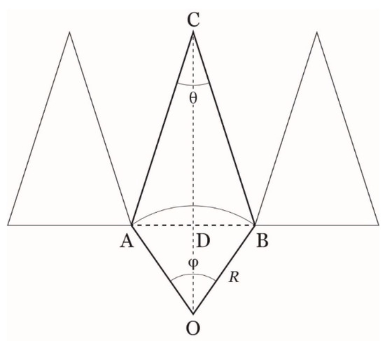
Figure 1.
Geometry for finding the relationship between the geocentric angle and aperture angle (the main antenna lobe, e.g., at dB gain) of the downlink and uplink antennas of the GeoSurf. This situation, with no overlapping of the service areas, is found only at the equator. O is the center of the Earth; AB is the approximate diameter of the service area. is the Earth radius, the segment CD gives the (approximate) height of the orbit from the surface. The connected satellite is at C. The triangles at left and right give the position and service area of the adjacent satellites in the same orbit plane in the North−South direction, or in adjacent orbit planes in West−East direction but only at the equator (no overlapping).
Now let us assume that the orbital planes of the constellation are separated in longitude by the same angle , therefore the adiacent orbit planes are angularly space ° to West and East.
This assumption means that the distance between close satellites belonging to adjacent orbit planes is largest at the equator and “zero” at the poles. Viewed from an inertial observer (i.e., an observer outside the Earth), the GeoSurf constellation would appear made of satellites moving synchronously (e.g., from North to South) along the meridians. Viewed from the Earth, the satellites would be moving South−West coming from the North−East. Therefore, if we assume that at a site the connection is, at a moment, with a satellite at the local zenith, this satellite would belong to the adjacent orbit plane to the East. After the time taken by the Earth to rotate to the East, the connection would be with a satellite belonging to the next adjacent orbit plane to the East, and so on. In other words, as anticipated, any site at any latitude will view a distributed geostationary satellite orbiting at that latitude.
In conclusion, the number of orbital planes of the GeoSurf constellation is:
Combining Equations (1) and (2), we get the total number of the satellites of the constellation:
Figure 2 shows as a function of the geocentric angle . ranges from 2592 for to 288 for .
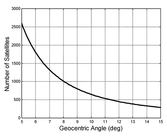
Figure 2.
Total number of satellites in the design of the GeoSurf constellation. This number is independent of the altitude of the GeoSurf constellation. ranges from 2592 for to 288 for for .
Now, let us assume the fundamental hypothesis that both all satellites and the transmitters/receivers on the Earth have fixed antenna pointing (no steering), both directed to the local vertical direction, i.e., to the local zenith. Therefore, these assumptions make us emulate a receiver/transmitter located at the equator that connects to a geostationary satellite stationing at the same longitude of the site (zenith path). Any transmitter/receiver will connect to the satellite entering its service area. For example, the satellite will be seen coming from the North East if the satellite is orbiting from the North Pole to the South Pole and the site is in the Northern Hemisphere. Because the satellite cannot be at the zenith all the time when crossing diagonally the service area, although it is very close to it, the link budget will lose 3 dBs on the side of the receiver, and 3 dBs on the side of transmitter when the satellite is entering/leaving the service area.
When the sites are really at the equator, with the above assumptions there is no overlapping of the dBs footprint of each satellite. For all different latitudes, there will be overlapping, the larger the closer to the poles. The overcrowding of the satellites at the high latitudes is a drawback of the Walker star constellation, but this effect can be partially taken care of if the orbit planes are inclined just a little bit more (or less) than 90° [1]. In any case, as for all constellations, a careful frequency planning and frequency reuse must be considered.
The Walker star constellation, as noted in Section 1, makes easier the use of inter-satellite links both within the same orbit plane (intra links) and with adjacent orbit planes (inter links). Let us now explore, in the next section, the geometrical and radio electrical parameters of the GeoSurf design.
3. Geometrical and Radio Electrical Parameters
Let us derive the fundamental relationships among the geometrical parameters, according to the geometry of Figure 1. For the purpose of illustration, we consider four typical altitudes: km for the geosyncronous orbits, km for typical MEO altitude, km for low MEO altitude and km for a LEO altitude. Given the geocentric angle , the radius of the Earth km, the altitude (km) of the satellite from the surface, the antenna dB angle is given by:
For instance, when , km (GEO), we get , see Figure 3. According to Kepler’s third law, the period T (in seconds) of the orbit is given by:
where GM = 398,600.5 km3s−2.
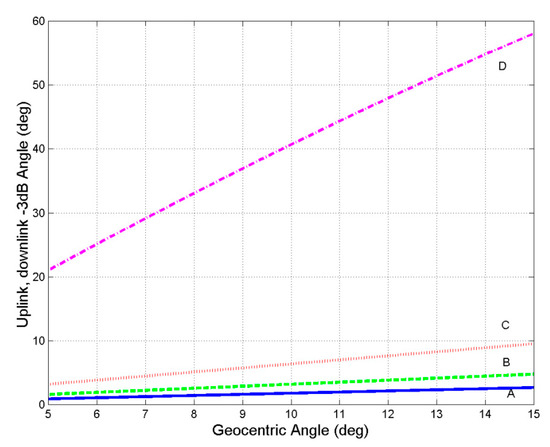
Figure 3.
Up−link, down−link and service area angle ( dB) of the GeoSurf constellation design, as a function of the geocentric angle . A refers to km; B to km; C to km, D to km.
Therefore, for , for example, at the GEO altitude the time taken to cross the service area, of size about 1670 km, is 60 min, as Figure 4 shows.
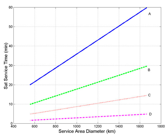
Figure 4.
Satellite service-area time as a function of the service area diameter for the GeoSurf Constellation. A refers to km; B to km; C to km, D to km.
Figure 5 shows the gain of the antennas (satellites and Earth transmitters/receivers) versus the approximate service area diameter. The gain is independent of frequency because it is a function of the dB aperture angle of the main lobe, which determines the service area diameter reported in abscissa. In fact, for a parabolic antenna of diameter (m) and efficiency , the gain is given by:
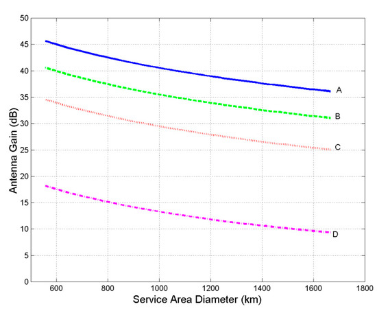
Figure 5.
Antenna gain as a function of the service area diameter for the GeoSurf constellation. Antenna efficiency is 0.6. A refers to km; B to km; C to km, D to km.
Now, the dB antenna main lobe angle is give by:
where (m) is the wavelength. Therefore, after solving Equation (7) for and substituting it in Equation (6), the antenna gain results indepedent of , and hence of frequency, as is given by:
However, the physical dimension of the antennas (which affects satellite weight, etc., and ground station costs) depends on frequency, as Figure 6 and Figure 7 show for the gain reported in Figure 5, as example, at 20 GHz (downlink) and 30 GHz (up-link), frequencies adopted at Ka Band, while Figure 8 and Figure 9 show the dimensions of the antennas at 40 and 50 GHz frequencies. As these figures show, the size of the antennas is always very small, so that they can be very easily installed onboard the satellites, even onboard small ones, and easily installed at customer’s premises, even if looking upwards to the zenith.
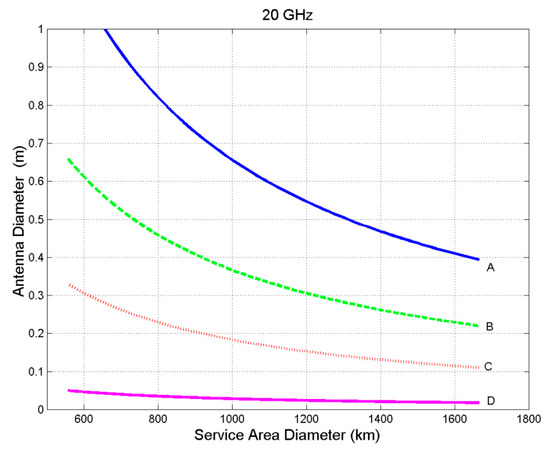
Figure 6.
Antenna diameter as a function of the service area diameter, at 20 GHz for the GeoSurf constellation. A refers to km; B to km; C to km, D to km.
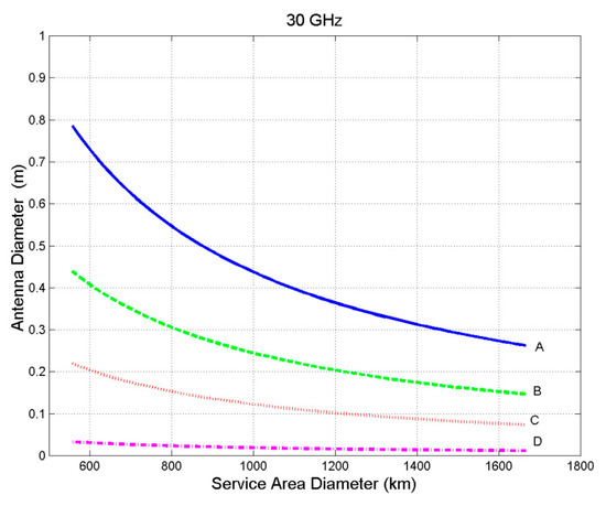
Figure 7.
Antenna diameter as a function of the service area diameter, at 30 GHz for the GeoSurf constellation. A refers to h = 35,876 km; B to h = 20,000 km; C to h = 10,000 km, D to h = 1500 km.
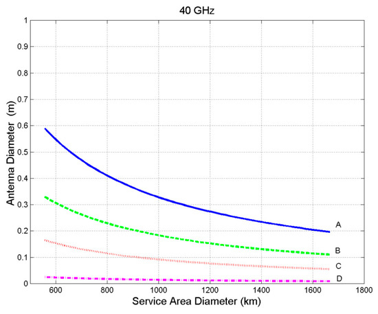
Figure 8.
Antenna diameter as a function of the service area diameter, at 40 GHz for the GeoSurf constellation. A refers to h = 35,876 km; B to h = 20,000 km; C to h = 10,000 km, D to h = 1500 km.
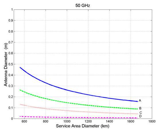
Figure 9.
Antenna diameter as a function of the service area diameter, at 50 GHz for the GeoSurf constellation. A refers to h = 35,876 km; B to h = 20,000 km; C to h = 10,000 km, D to h = 1500 km.
To guarantee the minimum signal-to-noise ratio required in the design, the radio frequency power onboard the satellites will largely depend on the free space distance. In other words, keeping constant the minimum signal-to-noise ratio in any possible propagation conditions, the frequency band (therefore, working always with the same tropospheric fading), the ultimate variable that determines the necessary power is the (practically zenith) distance between the satellite and the ground station, and therefore it sets the satellite constellation features.
4. Discussion and Conclusions
At this stage of developing GeoSurf constellations, we can draw only some general remarks, summarized in Table 1.

Table 1.
General characteristics (advantages and disadvantages) of the most popular constellations (identified by their altitude above the Earth surface) compared to the GeoSurf constellation. It is assumed that the frequency band and worldwide communication service type are the same for all systems.
One of the main advantages of the GeoSurf design is having zenith paths worldwide. With the GeoSurf constellation, we do not need steering antennas, the tropospheric propagation fading is minimized both for the stationary fading due to water vapor and oxygen, and for rain attenuation, because at zenith the path length in the troposphere is shortest [16]. The footprint of a single satellite is always the same, therefore making the design easier. However, several footprints can overlap with possible frequency interference, to be avoided by a careful frequency plan and coding. The Doppler phenomena are largely minimized because the connected satellite would be always viewed almost at the local zenith. The extra free−space loss, due to the fixed pointing of all antennas, is 6 dBs when the satellite enters or leaves the local service area. The connections among the satellites are easier to establish because of the constant positions along an orbital plane or adjacent planes, although with variable distances. The number of satellites is much less than that of a current large constellation proposal (Starlink). The main drawback is the large number of satellites crowding at high latitudes, a problem, however, that could be eased by slightly changing the polar orbits inclination. Because the GeoSurf constellation design can be applied to any orbit altitude, we could design a large number of GeoSurf constellations, by varying the altitude. We have presented some particular and popular orbit altitudes, just to show what could be done and to orient readers. Lower altitudes could also be used, such as, for example, 600 km, suitable for the very small cube satellites [17,18]. Of course, any satellite of the GeoSurf constellation could be linked to a real geostationary satellite and many architectures are possible. The same overall design could be considered for future large−scale human settlings on Mars.
In conclusion, GeoSurf constellations could effectively replace most of the actual constellations for Internet applications. However, as any new complex satellite constellation design, its possible implementation requires many feasibility studies, especially from the point of view of space companies, a task well beyond this theoretical paper.
Funding
This research received no external funding.
Conflicts of Interest
The author declares no conflict of interest.
References
- Su, Y.; Liu, Y.; Zhou, Y.; Yuan, J.; Cao, H.; Shi, J. Broadband LEO Satellite Communications: Architectures and Key Technologies. IEEE Wirel. Commun. 2019, 26, 55–61. [Google Scholar] [CrossRef]
- Qu, Z.; Zhang, G.; Cao, H.; Xie, J. LEO Satellite Constellation for Internet of Things. IEEE Access 2017, 5, 18391–18401. [Google Scholar] [CrossRef]
- Chotikapong, Y.; Cruickshank, H.; Sun, Z. Evaluation of TCP and Internet Traffic via Low Earth Orbit Satellites. IEEE Pers. Commun. 2001, 8, 28–34. [Google Scholar] [CrossRef]
- Di, B.; Song, L.; Li, Y.; Poor, V.H. Ultra-Dense LEO: Integration of Satellite Access Networks into 5G and Beyond. IEEE Wirel. Commun. 2019, 26, 62–69. [Google Scholar] [CrossRef]
- Fenech, H.; Tomatis, A.; Amos, S.; Soumpholphakdy, V.; Serrano Merino, J.L. Eutelsat HTS systems. Int. J. Satell. Commun. Netw. 2016, 34, 503–521. [Google Scholar] [CrossRef]
- Hasan, M.; Bianchi, C. Ka band enabling technologies for high throughput satellite (HTS) communications. Int. J. Satell. Commun. Netw. 2016, 34, 483–501. [Google Scholar] [CrossRef]
- Katona, Z.; Clazzer, F.; Shortt, K.; Watts, S.; Lexow, H.P.; Winduratna, R. Performance, cost analysis, and ground segment design of ultra high throughput multi-spot beam satellite networks applying different capacity enhancing techniques. Int. J. Satell. Commun. Netw. 2016, 34, 547–573. [Google Scholar] [CrossRef]
- Vasavada, Y.; Gopal, R.; Ravishankar, C.; Zakaria, G.; BenAmmar, N. Architectures for next generation high throughput satellite systems. Int. J. Satell. Commun. Netw. 2016, 34, 523–546. [Google Scholar] [CrossRef]
- Li, S.Y.; Liu, C.H. An Analytical Model to Predict the Probability Density Function of Elevation Angles for LEO Satellite Systems. IEEE Commun. Lett. 2002, 6, 138–140. [Google Scholar]
- Matricciani, E. Space communications with variable elevation angle faded by rain: Radio links to the Sun–Earth first Lagrangian point L1. Int. J. Satell. Commun. Netw. 2016, 34, 809–831. [Google Scholar] [CrossRef][Green Version]
- Matricciani, E.; Riera, J.M. Variable elevation–angle radio links faded by rain at Ka Band from Madrid to the Sun–Earth Lagrangian point L1. In Proceedings of the 22th Ka and Broadband Communications Conference, Cleveland, OH, USA, 17–20 October 2016. [Google Scholar]
- Walker, J.G. Continuous Whole−Earth Coverage by Circular-Orbit Satellite Patterns; Technical Report 77044; Royal Aircraft Establishment: Farnborough, UK, 23 September 1977. [Google Scholar]
- Radhakrishnan, R.; Edmonson, W.W.; Afghah, F.; Rodriguez-Osorio, R.M.; Pinto, F.; Burleigh, S.C. Survey of Inter-Satellite Communication for Small Satellite Systems: Physical Layer to Network Layer View. IEEE Commun. Surv. Tutor. 2016, 18, 2442–2473. [Google Scholar] [CrossRef]
- Matricciani, E.; Babuscia, A. A belt of satellites in low equatorial orbits simulating the geostationary orbit. In Proceedings of the 30th AIAA International Communications Satellite Systems Conference (ICSSC), Ottawa, ON, Canada, 24–27 September 2012; pp. 1–15. [Google Scholar]
- Lee, S.; Wu, Y.; Mortari, D. Satellite constellation design for telecommunication in Antarctica. Int. J. Satell. Commun. Netw. 2016, 34, 725–737. [Google Scholar] [CrossRef]
- Recommendation Itu-R P.618-8 Propagation Data and Prediction Methods Required for the Design of Earth-Space Telecommunication Systems. Available online: https://www.itu.int/dms_pubrec/itu-r/rec/p/R-REC-P.618-13-201712-I!!PDF-E.pdf (accessed on 17 January 2020).
- Babuscia, A.; Corbin, B.; Jensen-Clem, R.; Knapp, M.; Sergeev, I.; Van de Loo, M.; Seager, S. Commcube 1 and 2: A Cubesat series of missions to enhance communication capabilities for CubeSats. In Proceedings of the 2013 IEEE Aerospace Conference, Big Sky, MT, USA, 2–9 March 2013; pp. 1–19. [Google Scholar]
- Su, W.; Lin, J.; Ha, T. Global communication coverage using Cubesats. In Proceedings of the IEEE 7th Annual Computing and Communication Workshop and Conference (CCWC), Las Vegas, NV, USA, 9–11 January 2017; pp. 1–7. [Google Scholar]
© 2020 by the author. Licensee MDPI, Basel, Switzerland. This article is an open access article distributed under the terms and conditions of the Creative Commons Attribution (CC BY) license (http://creativecommons.org/licenses/by/4.0/).