1. Introduction
Our homes can be better in terms of resource management and user interactions. The concept of smart homes can change the way we interact with our homes. The home will stop being a static aggregation of resources and will be an active asset that can help and support its users. A smart home may have multiple purposes, such as home automation [
1,
2], energy management [
3,
4,
5,
6], security and safety [
7,
8,
9] or even assisted living [
10,
11,
12]. However, regardless of its purpose, smart homes should provide interoperability to enable the integration of multiple systems—from multiple brands and manufactures.
From an energy point of view, there are some advantages in the smart home concept, where the home has smart capabilities to manage energy resources [
13]. This type of smart homes enables the active participation of residential homes in the smart grid environment [
14], bringing clear advantages to the users. Moreover, energy management systems can use learning algorithms to better understand the users’ preferences [
15].
DoMAIns (recursive acronym for “Domain-based Modeling for Ambient Intelligence”) proposed in [
16], Vi-SMARt (Virtual, Social, Multi-sensorial and Adaptive systems for the Rehabilitation of people with ABI) proposed in [
17] and the proposed smarter smart home in [
18] focus on user interactions with the system using a residential context. These projects show the benefits and some of the possible applications of ambient intelligence (AmI) systems. In [
19], it is described an office and meeting room using an AmI system to improve the user comfort and interaction.
The test of hardware and wireless sensors are a key feature in AmI systems, where sensoring capabilities are mandatory. In [
20] and [
21] are proposed middleware architectures for sensor networks applications. The architecture proposed in [
20] also provides a testbed for AmI applications.
The use of domain models gives AmI the ability to understand the world. The domain can be represented using open ontologies or closed world representations. DoMAIns system, [
16], uses the combination of ontologies to understand their surroundings. In [
22] is used a set of ontologies to have better world knowledge regarding the assisted living field. In [
23] is proposed the CONSERT (CONtext asSERTion) context model to describe the situation of entities, regarding the interaction between persons, places, and objects.
AmI systems can benefit from the integration of artificial intelligence (AI) techniques [
24]. Vi-SMARt project, [
17], integrates an artificial neural network (ANN) to support learning from patient therapies. In [
25] it is used a clustering algorithm to perform the classification of users’ health. In [
24], AmI is seen from the perspective of AI and different uses of AI methods and techniques are identified for the following seven different phases of the intelligent behavior: interpreting the environment’s state; representing the information and knowledge associated with the environment; modeling, simulating and representing entities in the environment; planning decisions or actions; learning about the environment and associated aspects; interacting with humans; acting on the environment.
AmI solutions require the integration of several operation systems and communication protocols [
26]. The application of single-board computers (SBC) to promote the heterogeneity of the system is a viable solution while decreasing deployment costs, as seen in [
25]. The application of SBC for smart sensors in manufacturing area can be seen in [
27].
The Intelligent of Home (IoH) platform, described in this paper, for AmI and context awareness management and support, is the main paper’s contribution. IoH main novelty and innovation it the ability to integrate and combine the inputs of multiple internet of things (IoT) devices as well as multiple smart home systems with contextual data. IoH is able to combine multiple data sources and produce contextual decisions and act over home resources. The resources’ actuation is done through integrated IoT devices and smart home systems. This paper details the proof of concept of IoH platform, presenting a real deployment in an office building to show the advantages of IoH platform as a context awareness system for smart homes. The IoH is deployed in one of our buildings. This paper shows the IoH capabilities as well as integrated devices and systems. The IoH platform does not have any associated hardware and exclusively uses third-party hardware.
After this first introductory section, this paper describes the IoH platform architecture in
Section 2.
Section 3 details and presents the integrated subsystems that were integrated into IoH platform.
Section 4 describes the deployed building as well as the metadata associated with each integrated IoT device and system.
Section 5 presents the IoH results while
Section 6 presents the main conclusions of this work.
2. IoH Architecture
The IoH platform was developed for context awareness and ambient intelligence solution to manage homes using a combination between market available smart devices and tailor-made subsystems that want to be integrated into IoH platform. The platform will combine sensing data with external data and user data to be able to manage the home according to its context and providing to the user an efficient and intelligent home. The main motivation behind IoH is its application for building’s management systems. IoH platform will enable the entire building’s control in the same platform and will enable the decision support according to the building’s context.
Most of IoT proposed architectures works on a conceptual level using individual IoT devices, while IoH will integrate full independent systems. In [
28] is proposed an IoT architecture for context-aware to help users getting services. In [
29,
30] gateway-enabled architectures are used for IoT, where gateways are used to simplify the development of horizontal platforms. In [
31] a decentralized architecture for resource utilization optimization.
The IoH architecture was designed for standalone applications. However, the integration of multiple devices and subsystems are allowed as well as communication with other IoH platforms for cooperative collaboration.
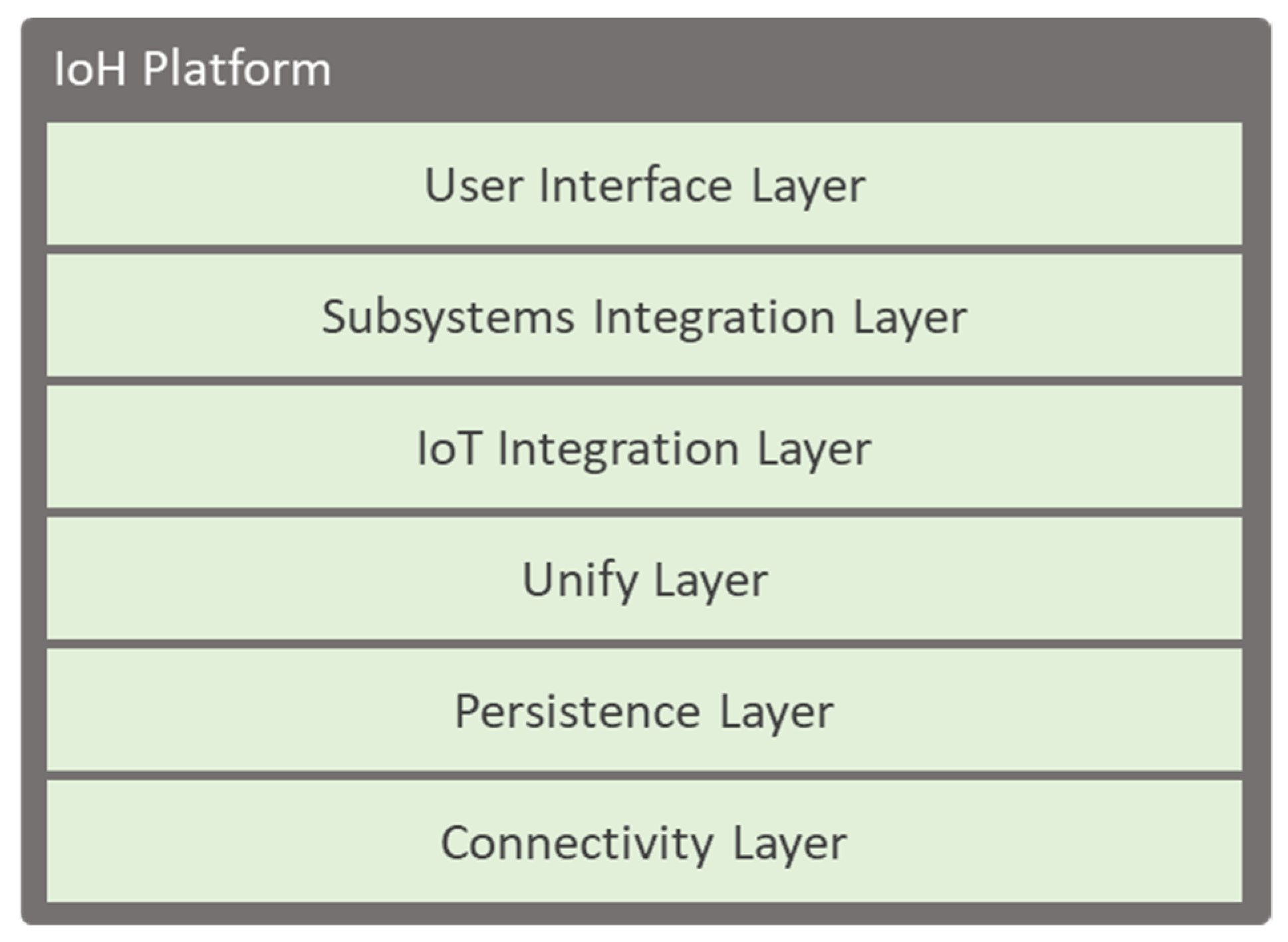
Figure 1 presents the proposed architecture for IoH platform. The IoH platform has an interconnected layer architecture to provide the final platform.
Each layer is responsible for a specific action and solves a part of the problem.
Section 2.1,
Section 2.2,
Section 2.3,
Section 2.4,
Section 2.5 and
Section 2.6 will describe in detail the motivation and functionality of each layer. For our implementation, a Raspberry Pi 3 Model B was used to develop the IoH platform. The use of such single-board computer enables a compact solution that is easily installed in a home without demanding a dedicated server or the use of external servers—making it completely private solution, by being a user-side platform.
2.1. Connectivity Layer
The IoH platform was designed as a standalone solution that does not have any dependence on other system or systems. The platform manages and takes actions without the necessary use of external services. However, this is simply not possible in this type of platforms. The connectivity layer is responsible for three things: connectivity with other IoH platforms to perform cooperative building management, connectivity with devices and resources, and connectivity with external data providers.
The need for collaboration with other IoH platforms appears for large buildings with multiple IoH platforms managing independent zones. For instance, in a large office building with multiple independent offices, where each office has its own IoH platform, and the building itself has an IoH platform for external sensors, such as temperature and luminosity, the building’s IoH platform can share the external sensor data with the offices’ IoH platforms.
The connectivity with devices and resources will be detailed in the descriptions of the IoT integration layer and the subsystems integration layer. The connectivity with external data regards public and subscription services, such as weather application programming interfaces (API) that can give important data and information to the platform in order to perform an efficient and intelligent building’s management.
2.2. Persistence Layer
All data is precious, and all data and actions should be stored. In IoH platform, the persistence layer is the layer responsible for storing all the data resulted from sensors, platform activity, and user actions. The persistence layer is responsible for storage mechanisms providing a storage class and storable interface to be used in objective oriented storable classes in the IoH platform.
The persistence layer is composed of multiple database drivers that enable the use of multiple databases technologies. The location of the database should be a combination of local and remote databases. The local database is for near present data and metadata, while the remote database stores the older historical data—also used for the backup and historical register.
Data needed for building’s management algorithms, such as forecasting, should be stored in the local database to improve the speed of data access. Storage time periods should be chosen according to each resource or device.
2.3. Unify Layer
The unify layer is responsible for the harmonization between the IoH platform and IoT devices and subsystems. IoH platform does not include hardware resources, being a software platform that uses third-party solutions to provide a context awareness and ambient intelligent platform for buildings. Therefore, the efficient and robust unification of third-party resources is necessary, providing integration and compatibility.
This layer is responsible to analyze and process the metadata of the integrated solutions and match contextual data in order to perform context awareness decisions and user suggestions. The integration will be more detailed in the next two subsections while the metadata description and application are seen in
Section 4.1 and
Section 5.3,
Section 5.4 and
Section 5.5.
2.4. IoT Integration Layer
IoH platform enables the integration of market IoT devices, such as smart plugs and sensors. The use of IoT devices in today’s buildings is a reality. At 2022 it is expected that at least one smart device is presented in 216.9 million homes worldwide [
32]. Therefore, better than redesign the wheel is to integrate market IoT devices that are capable to be used to produce the desired solution of IoH.
The integration of IoT devices is done by now by using Home Assistant (
https://www.home-assistant.io/) open source solution. Home Assistant enables the easy integration of multiple IoT devices while providing a RESTful API to monitor and control each individual device. The access of this API is used in IoH to enable the IoT devices integration.
In order to include IoT devices in the IoH platform, it is necessary to describe them in the IoH configuration. Metadata is associated with each IoT device to classify the device. Metadata regarding device location and associations—other devices that are connected to or affected by—also needs to be set. For instance, the integration of a smart plug that controls a heater must specify the room’s location. IoH platform will use and process the metadata to find correlations and context parameters.
2.5. Subsystems Integration Layer
Besides the integration of IoT devices, IoH platform also enables the integration of third-party independent systems. This layer enables the inclusion of other works that are more than simple IoT devices.
Section 3 of this paper will describe some of the subsystems that were integrated.
In this paper, a subsystem is defined as an independent system that can be continuously running. However, it is required that a subsystem allows remote connections to activate or deactivate the subsystem. The integration of such subsystems is more difficult and must be manually done. The metadata associated with the subsystem must be described like IoT device’s integration.
2.6. User Interface Layer
The user interface layer in the main bridge between users and IoH platform. Although the user interface is one of the key features of an application to be accepted by users, this will not be the focus of this paper. The main focus of this paper is the IoH platform and its contextual decisions.
This layer is at least one of two types: an API, or a graphical interface. The API implementation will open the IoH platform to multiple graphical interfaces, such as mobile and web. The graphical interface type is a local interface that runs only in the IoH platform, depending on the machine hardware (i.e., screen size and interaction possibilities).
The API solution is the most dynamic and recommended type because it will not close the system to a unique interface located in a unique front panel. However, the local graphical interface has advantages regarding the security, because it demands a user to the location. Therefore, a combined solution can be implemented where some functionalities are only available locally while others are available remotely (i.e., using an API).
3. Subsystems
IoH platform has been developed using the previous architecture discussed in
Section 2. This section will now detail five subsystems that were developed for IoH platform integration. A subsystem is an individual system contributing to the IoH knowledge and control.
3.1. Intelligent Light Control
The intelligent light control system was developed and implemented in one of our labs with a clear idea: to have a contextual awareness and fully autonomous system resulting in a consumption decrease. Because labs are used by multiple researchers and students, it was common to have the lights turned on even though there were no persons inside. The lab includes a total of five lamps and three windows.
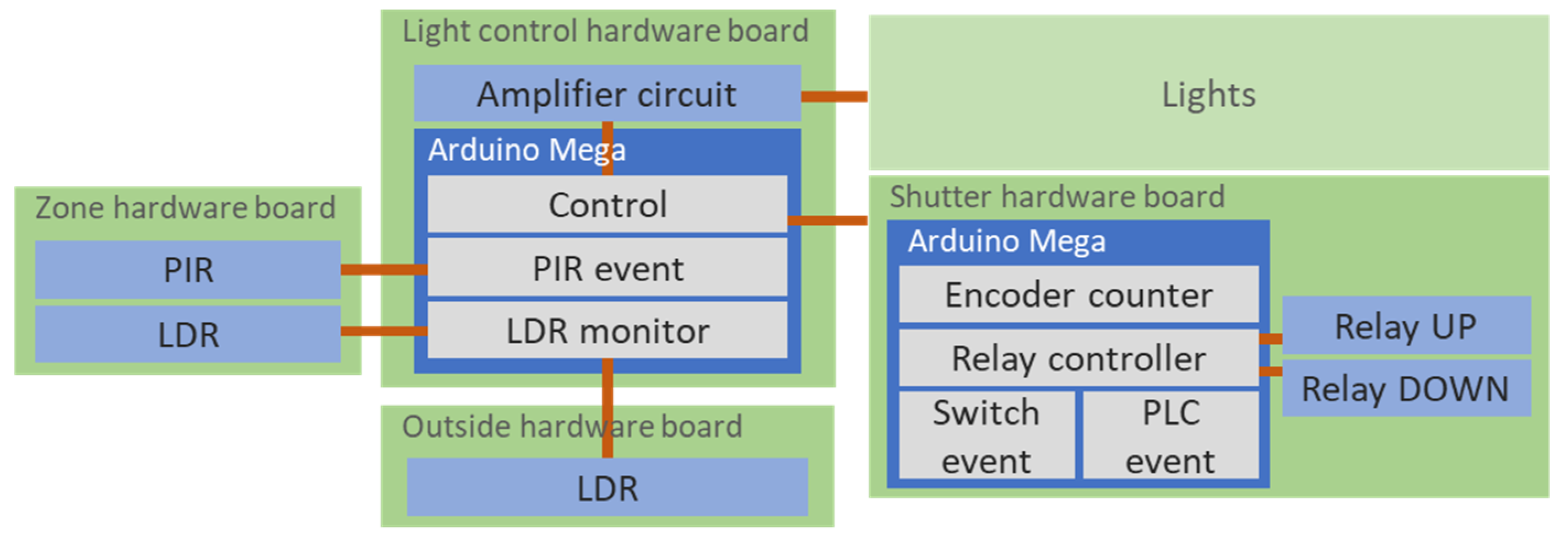
Figure 2 shows the intelligent light control system with its components. Physically, the system is divided into six boards: the light control hardware board were the system core is at, the outside hardware board that is placed outside of the building to measure the sunlight, three-zone hardware boards to measure each room zone, and the shutter hardware board that has a window’s shutter system. The system has a total of 5 controllable lamps connected.
For the system to be possible, the lights ballasts were changed to provide fine analog control over the light intensity—this is done using an analog signal from 0 V/DC to 10 V/DC. The system uses an amplifier circuit (
Figure 2) to amplify the 0–5 V/DC Arduino’s signals to 0–10 V/DC for the lamps control. The system also integrates three internal light dependent resistor (LDR) to measure the light intensity in three locations, three passive infrared (PIR) sensors to detect movement, and one LDR located in the outside of the windows to measure the external light.
The control of the windows’ shutters implies a change in the room’s light. Therefore, the shutters can be used to increase or decrease the external light entering into the room. For this, the shutter control of the three lab’s windows was integrated into the intelligent light control to promote the use of natural light.
The window’s shutters control, seen in the right side of
Figure 2, uses an Arduino Mega 2560 R3 to control two relays, for each window, connected to a 230 V/AC motor. The Arduino controls the relays according to commands provided by the wall switches or the programmable logic controller (PLC)—connected to the Arduino using Modbus/RTU protocol over RS485. To monitor the shutter’s position, an encoder was placed in the shutters’ motor. The communication between light control and shutter system is done using Modbus/RTU.
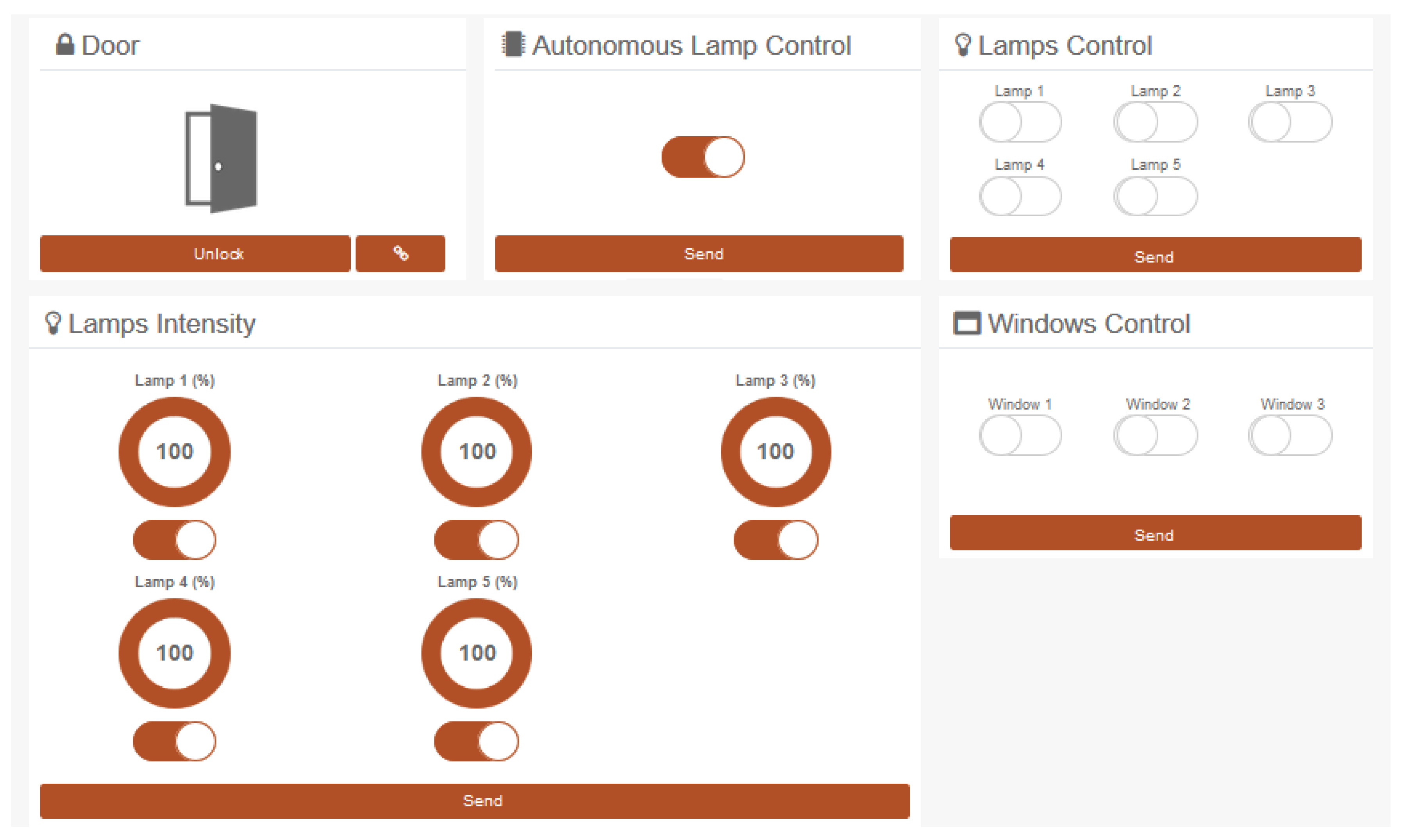
The room’s light control is done using a web interface with login, allowing the user to control the room’s light. A total of five individually controlled dimmable lamps are available in the room.
Figure 3 shows the existed webpage where it is possible to control the lights. This webpage was developed in PHP and allows the control of the building.
The system was built having assisted manual control and autonomous control. The assisted control monitors the control actions and provides the user with information regarding the windows’ shutters. For instance, every time a user wants to turn on the lights, the system will validate that control with the external light value, and if there are light in the outside, then the system will suggest the user to open the shutters before turning on the light, if the user agrees then the system will automatically open the shutters, in the other hand, if there are not external light or the user do not agree to open the shutters, then the system will turn on the lights.
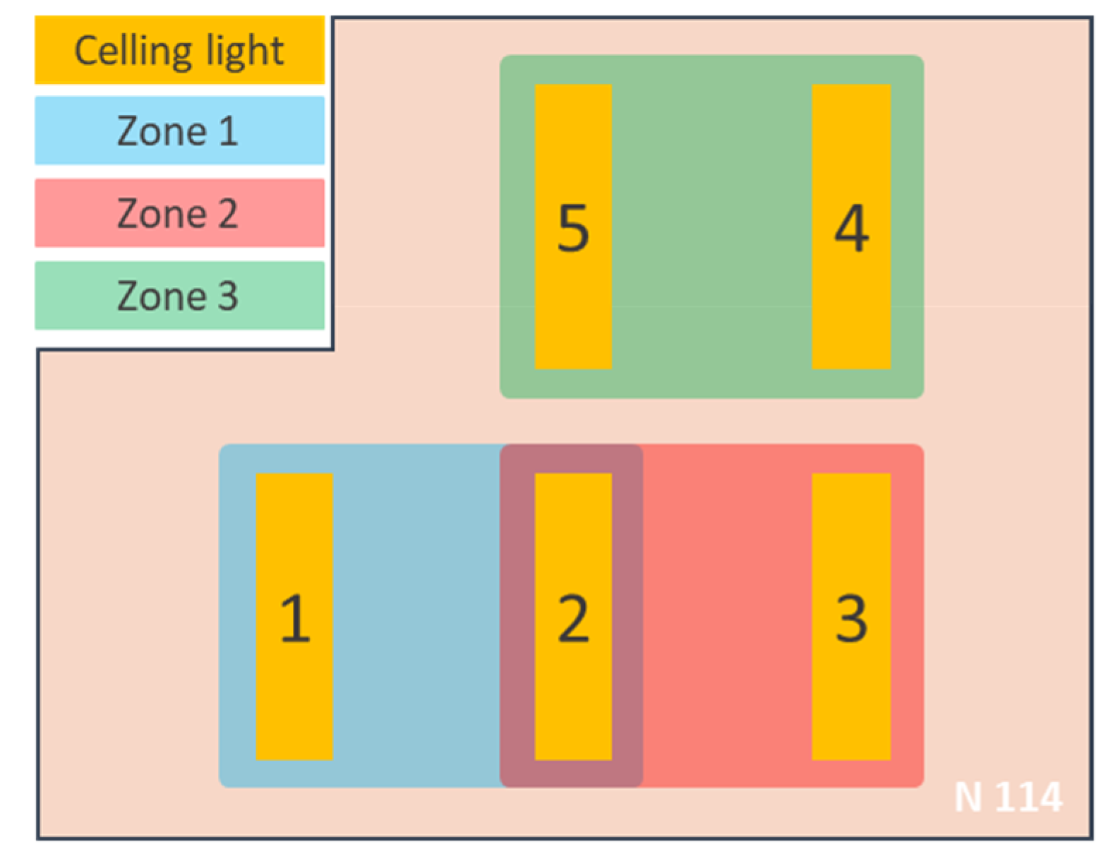
The lights autonomous control defines the individual control of three zones in the lab.
Figure 4 shows and identifies the lab layout and the autonomous control zones. Each zone has two lamps and three sensor boxes with one PIR sensor and one LDR sensor. Lamp 2 is shared by Zone 1 and Zone 2. The PIR sensor provides information regarding heat movement inside a zone, and when this occurs the zone’s lamps will be turned on. The LDR sensor will then adjust the intensity of the lamp to provide a 1000 lux intensity inside the zone. According to [
33], a 1000 lux value is recommended for detailed mechanical workshops. If no movement is detected in the last seven minutes, the lamps reduce their intensity to 400 lux, if no movement is detected in the next two minutes, then the lamps will be turned off. The reduction of the light in the autonomous control enables the user reaction when the system mistakenly assumes that there are no users inside a given zone.
By using the assisted manual control or the autonomous control, the system automatically adjusts the light intensity to reduce energy consumption—by not providing more than the necessary light. However, the user is able to surpass the system and manually adjust the light intensity as he/she wants.
3.2. Intelligent Television Brightness Control
In our lab, there is a television that continually presents the building’s photovoltaic generation and consumption. However, even though the television is only on between 8 a.m. and 8 p.m., its consumption is optimized and reduced if the brightness level is automatically controlled according to the occupancy of television vision range—in other words, if there is no one at television sight, then the brightness will be reduced.
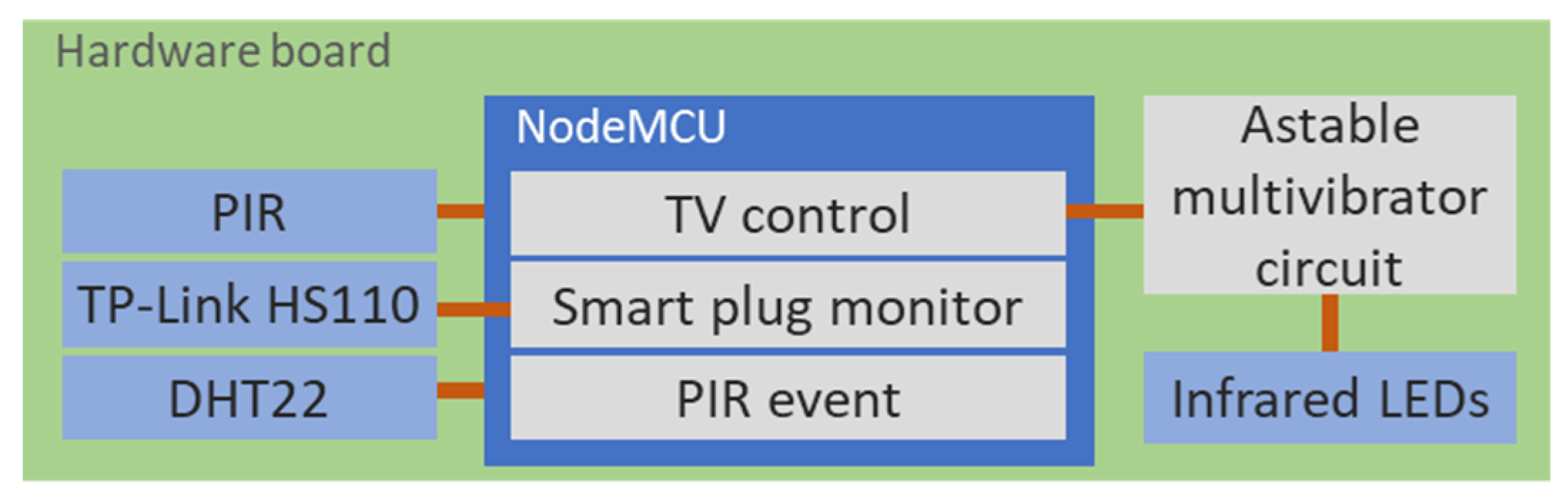
The intelligent television brightness control, seen in
Figure 5, uses a PIR to detect movement near the television and then controls the television using an infrared emitter connected to a NodeMCU ESP8266 module. The NodeMCU module reads the PIR movement and controls an LG television to switch between power modes—from the lower brightness mode to the higher brightness mode. For system calibration, it is used a TP-Link HS110 smart plug with energy monitoring. The system queries the smart plug consumption to detect the television’s power mode and then changes the power mode to the right mode. If there is no movement for five minutes, the system will change the brightness to the lower level, otherwise, the system will change the power mode to its brighter mode.
Figure 5 shows the developed board, with its components, for the intelligent television brightness control system. The NodeMCU reads the sensor data (i.e., PIR and DHT22) and then controls the television according to the information received by the smart plug. The use of the NodeMCU framework does not allow the direct control of the infrared LED because it only provides a 1 kHz clock. To achieve the necessary frequency of 38 kHz, an astable multibrator circuit was developed.
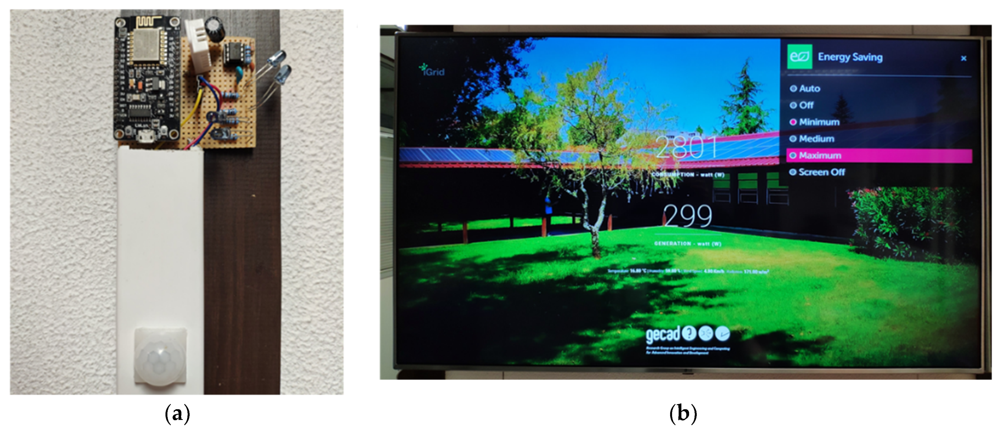
Figure 6a shows the developed board and in
Figure 6b it is shown the television during the changing of power mode. Because we were not able to find a unique infrared code to change the power mode, a sequence of infrared signals was performed, the order and action of these signals are:
Power mode menu—this infrared signal initially opens the power mode menu showed in
Figure 6b;
Power mode menu—after the menu is open, the same signal is used to change the selected power mode, therefore it is repeatedly sent to the television to choose the right power mode, the number of repetitions is calculated according to the smart plug consumption that identifies the current power mode;
Ok—this is the signal of the Ok button in order to choose the selected power mode.
3.3. Intelligent Desk Light Control
The control of illumination in an office environment has clear advantages regarding energy efficiency and user comfort. However, this type of solution can also be implemented for residential building in working computer desks. The intelligent desk light control system enables the automatic control of the working light regarding environment light and user presence.
The biggest difficulty of such a system is the identification of persons, if the system can detect persons then it is easy to control the light according to the environment light. To solve this issue, the system was divided into two parts: the sensing hardware, and the processing software.
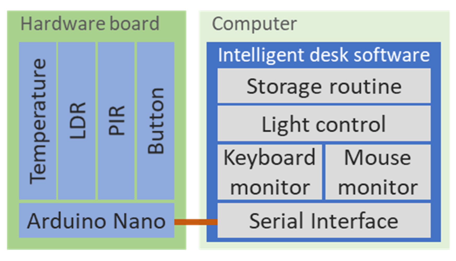
Figure 7 shows the hardware and software of the intelligent desk light control system. The hardware connects to the software using a serial interface. The software is responsible to read the hardware sensor data, monitor the computer’s keyboard and mouse, controls the desk light and store all the system’s data.
The hardware includes the majority of sensors used in the system.
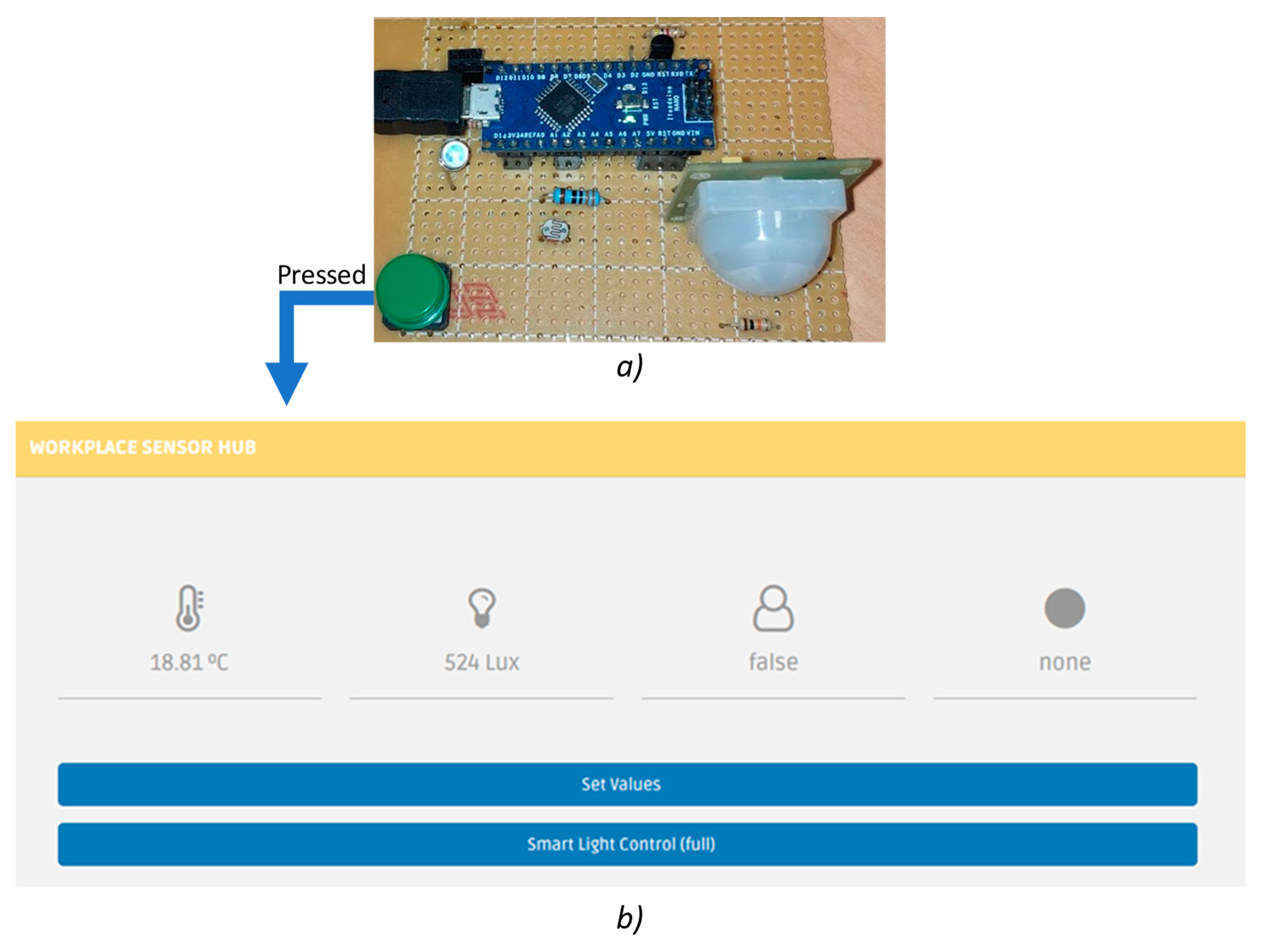
Figure 8a shows the developed board built with its components. The sensors used allows the measuring of temperature, luminosity (LDR), and movement (PIR). The button on the board enables the user configuration when it is pressed a website opens in the user’s browser to enable system configuration (
Figure 8b). An Arduino Nano V3.0 is used to process sensors’ data and send them to the computer through a USB cable—this cable is also used to feed the circuit with 5 V/DC.
The software, developed in Java, reads data from Arduino Nano, processes the information, stores the data and controls the light. The software is also responsible to detect mouse movements and pressed keyboard keys. The combination of sensing data from software and hardware provides a unique system that has very little error.
The PIR of the hardware is good to detect movement, for instance, it is very effective detecting the person arriving and leaving the desk. However, the minor movements produced by the persons when working at the desk are not enough to trigger the PIR movement. Moreover, because the used PIR is not able to detect movement directions—when a person arrives or leaves—the exclusive use of the PIR to detect persons in a working desk is not sufficient. To solve this issue, the intelligent desk light control uses the Java software to detect if a person is using the computer—by reading mouse and keyboard inputs. The combination between the PIR and the software is able to provide good quality data that can detect, with low error, the presence of a person working in a computer desk.
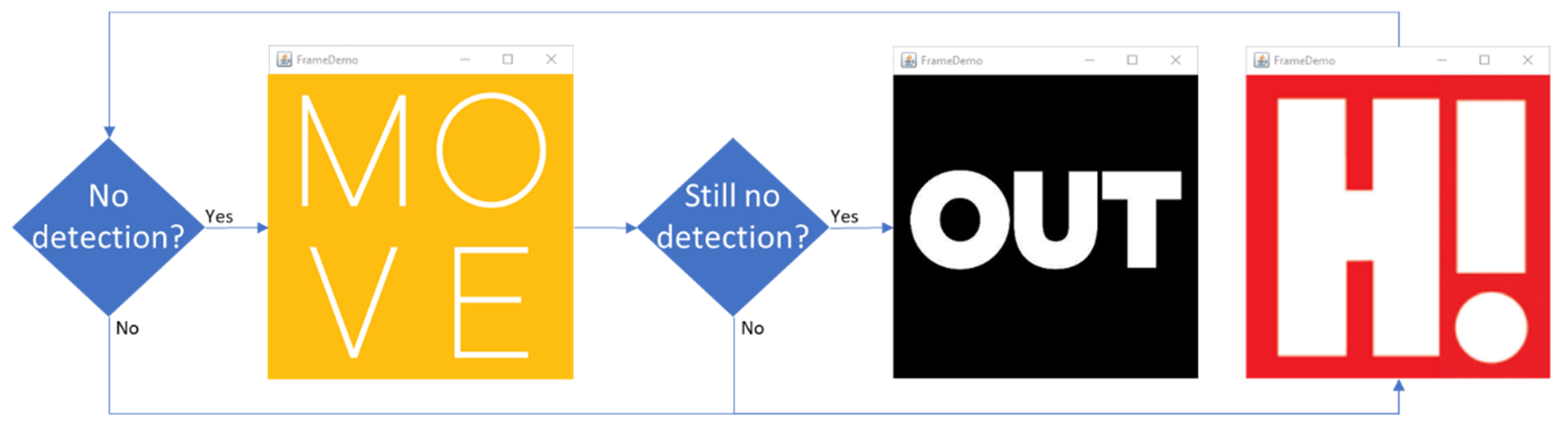
To prevent system errors, visual signals were used to give information and feedback to the user.
Figure 9 shows the messages available in the computer to warn the user. If the system does not detect a person, a “Move” message is displayed and the user has some time to act, otherwise, the light will be turned off. The two
ifs of
Figure 9 have associated configurable time periods, for instance, only if no one is detected during a five-minute period that the “Move” message appears, and if no one is still not detected for one more minute then the “Out” message appears.
The system has a total of five control modes that are settable in real-time using the webpage accessible by the press of the hardware button:
None—in this case, no control is done by the system;
On—the system will turn on the light, at 100%, every time it detects a person in the computer desk;
Off—the system will turn off the light every time a person leaves the computer desk;
On/Off—the system provides the combination of the On and Off modes, being able to turn on, at 100%, and turn off the light;
Full—the system will turn on and off the light, according to desk occupancy, and will automatically adjust the light intensity to meet the set target.
In the configuration webpage, the user can set the light level that he/she wants to have in his/her desk. To do so, the user must manually control the light intensity and when it finds their desired level of light, he/she just need to press the ‘set values’ button available in the interface. This way, the system will store the light level as the new target and will be able to provide that light level during the entire day. The adjustment of light will use the LDR of the hardware; to read the existing light in the room, and then increases or decreases the intensity of the artificial light.
During the development and implementation of this system in our offices, a problem appeared during the use of the computer’s remote access. By using the remote access functionality to access the computer of the monitored desk, the Java software was able to read the mouse and keyboard inputs, even though the user was not physically there—because he/she were using a remote session. Therefore, a new solution needed to be implemented. The change that solved our problem was the use of the PIR to detect a person arriving at the desk and not to use the mouse or keyboard to detect arrivals. The final solution uses the PIR to detect the arrival of a person and the PIR, mouse and keyboard to monitor if the person is still on the computer desk. Only when the PIR, mouse and keyboard stop detecting movement that the system assumes that no one is there, and when this happens the system presents the “Move” message, so the user can move if he/she is still there.
3.4. Intelligent Persons Counter System
The identification of occupancy and the number of persons inside a building is important for energy management algorithms and building optimizations because the presence of people drastically changes the optimization results. However, the simple counting of persons is a very complex and difficult task. The intelligent persons counter system uses a webcam to detect the movement of persons in the main hallway of our building.
Previous solutions were tried with infrared line sensors. However, they resulted in higher errors and were not efficient enough to provide a precise counter system. Some types of clothes and the line infrared sensor became problems that seemed impossible to overpass. The sensors also had some false positives that mislead the system. The solution adopted uses a webcam and computer vision algorithms to process the webcam image, this enables a more precise and stable system.
The system was developed in Python and runs on a desk computer where the webcam is connected. The webcam is located in the hallway’s ceiling and reaches all the hallway in order to detect any movement.
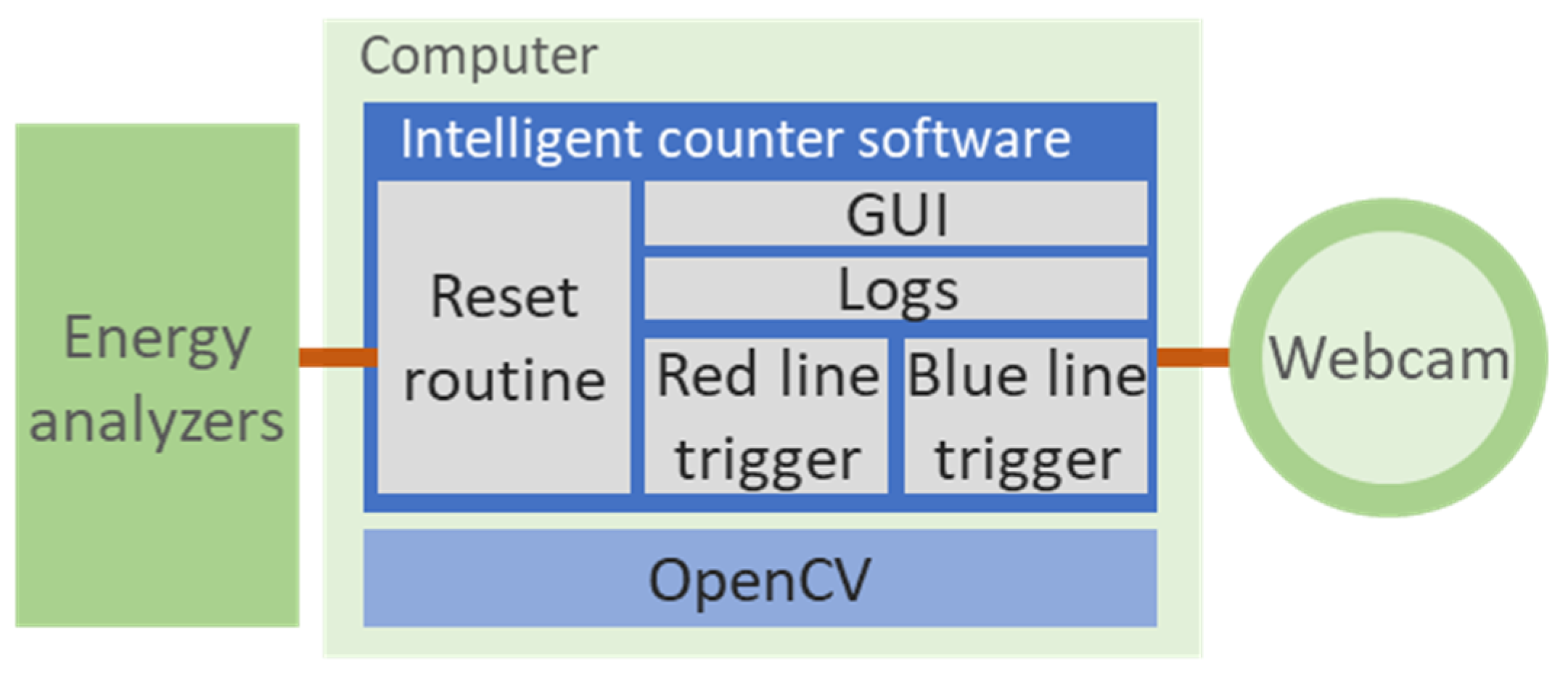
Figure 10 shows the connections between the system modules. Beside the webcam, the system uses another external connection to energy analyzers in order to execute the system reset routine.
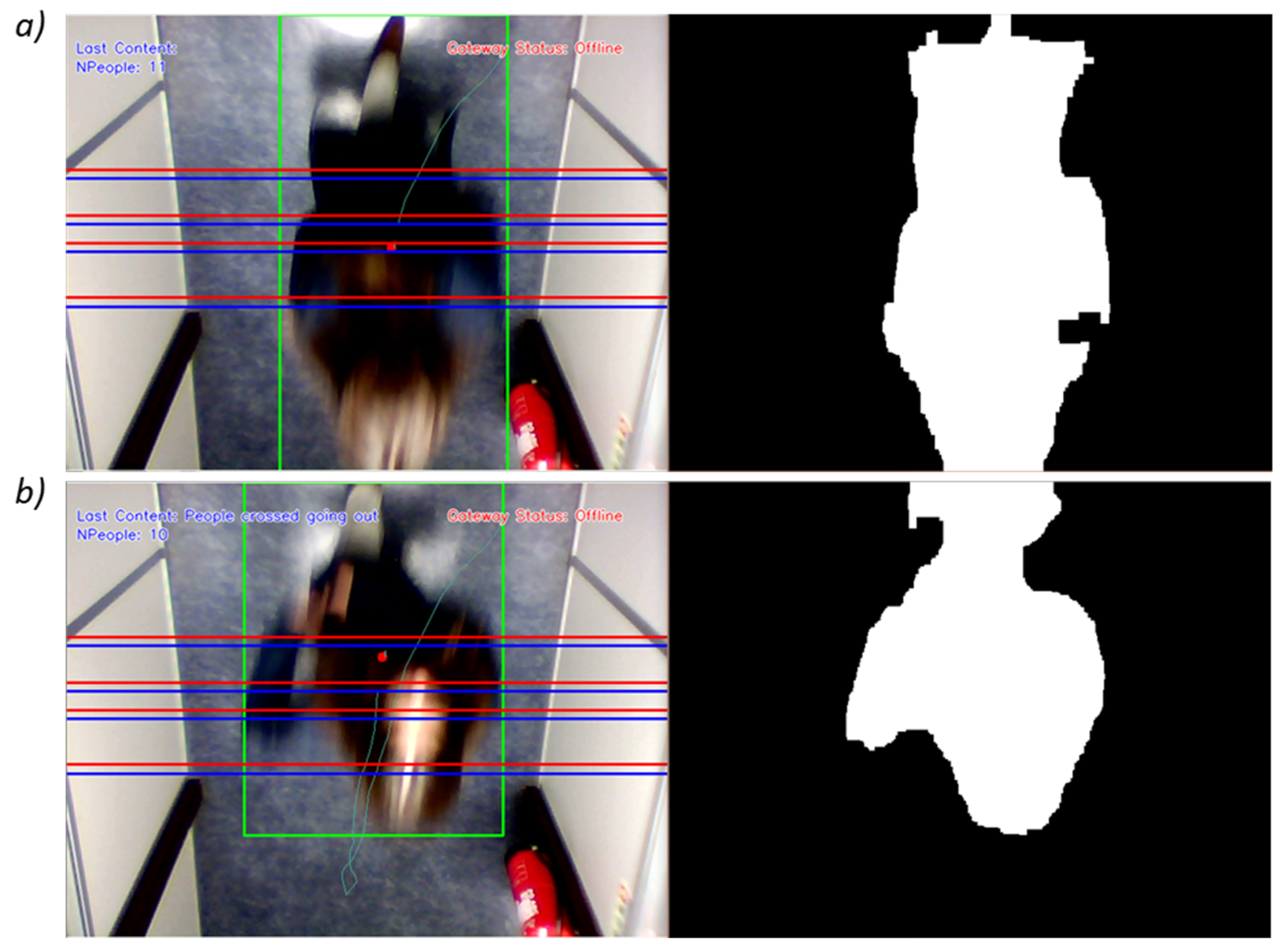
The Python software is able to detect a person and trace their route. This tracing can be seen on the left screen of
Figure 11 where a person is detected and marked within a green rectangle and where the person’s route is represented by a green line. The blue and red lines are specified limits that trigger events every time a person collides with it.
Using the open source computer vision library (OpenCV) the system is able to read and process the video feed of the USB webcam. Then the software separates and identifies the video background from the moving objects, displaying a black and white frame where the background is represented in black and moving objects are represented in white, this black and white frame can be seen in the right side of
Figure 11. To detect the background objects, the software compares previous frames, if an object is still in a set number of previous frames, then it is identified as being part of the background.
The entering of a person in the frame generates a white spot. The software uses frame filters to avoid and decrease the amount of interference generated by reflections and other signal distortions and noise. If the white spot is bigger than the defined target, the system assumes it is a person and starts the identification of the spot, to delimitate its borders. These borders are defined by the green line rectangle of
Figure 11. With the limits delimitated, then the system starts the object tracking.
The tracing of an object is drawn in the graphical interface, as seen in
Figure 11. Every time a person passes a blue or red line, a trigger is activated. Using the blue and red line triggers sequence, the software is able to detect the direction of a person—to detect if the person in entering or leaving.
During the implementation, new blue and red lines were added and experimented in order to achieve a satisfactory result. The low ceiling of the hallway and the lack of natural light were a problem that was solved using more blue and red lines and with artificial light that must be turned on—otherwise, the webcam will not be able to see any person. One error that was not possible to solve, was the error produced by two persons passing at the same time. Because the hallway is narrow and the camera angle is too short, when two persons pass at the same time the software will see only one person—as is the combination of both. This happens because the distance from both persons will be too short for effective individual identification. This was not an easy problem to solve, however, some solutions are: narrow down even more the hallway so only one person passes at a given time, and/or use a high-resolution camera with a higher angle so more hallway can be filmed and monitored.
To track errors and system’s actions, a logging mechanism was included. And because all systems fail, a reset mechanism was implemented to correct counter errors. The building can have persons at any time at any day, therefore an automatically hour reset (e.g., at 3 p.m.) was not a viable solution. To solve this issue, the system uses the photovoltaic generation value and the individual room’s consumptions values. If the electrical generation is equal to zero it means that there is no sunlight—no sunlight or very close to none—and if so, if the rooms’ consumptions are low and the light consumption of each room is equal to zero it means that there is no person inside the building. With this information, the system resets itself if there is no sunlight and the building is totally dark. The reset mechanism is activated every 5 min when the counter number is bigger than zero—it is not possible to have negative numbers; the system not counts people leaving the building if the counter is already set to zero. If a person is in the total dark inside the building the system will not see him/her, this is a situation that was not considered in order to provide a reset mechanism to the system.
3.5. Intelligent HVAC Control
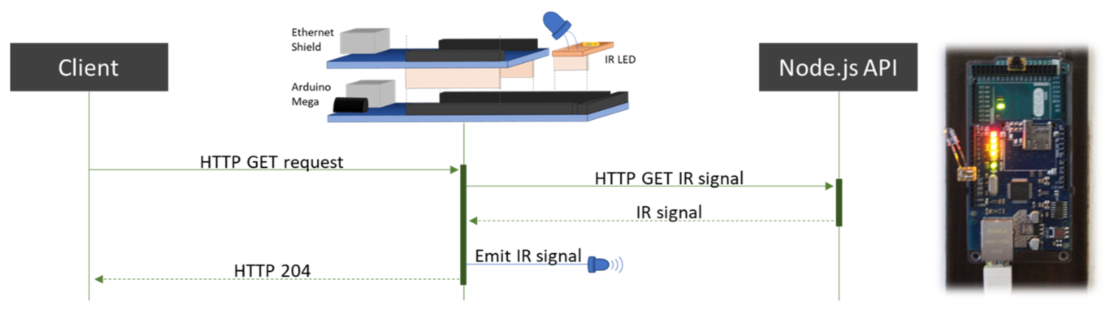
The control of heating, ventilation and air conditioning (HVAC) devices in buildings can have a big impact on energy consumption. In our solution, it was integrated a system that enables the autonomous control of an air conditioning unit by forecasting the room’s usage in the next time period. To provide HVAC control, an infrared universal emitter device was built using open-source hardware and software.
The infrared control device uses an Arduino Mega with an infrared emitter that accepts HTTP GET requests in a similar way as a RESTful API. When receiving an HTTP request, the Arduino will query a RESTful API, created in Node.js, that retrieves the infrared code that the Arduino needs to emit. Arduino has memory limitations that do not allow the store of all possible infrared signals. The use of external server overpasses this limitation and can store a huge number of signals. Moreover, this solution provides easy system scalability—when a new signal is stored at the server, it will immediately be accessible by all the Arduinos—and provides a single location for all systems that use infrared signals to control resources, such as air conditioners, television sets, and projectors.
Figure 12 shows the infrared device and the sequence diagram for each control request.
With the control solved, the idea was to forecast the room’s usage in the next hour to control the HVAC accordingly.
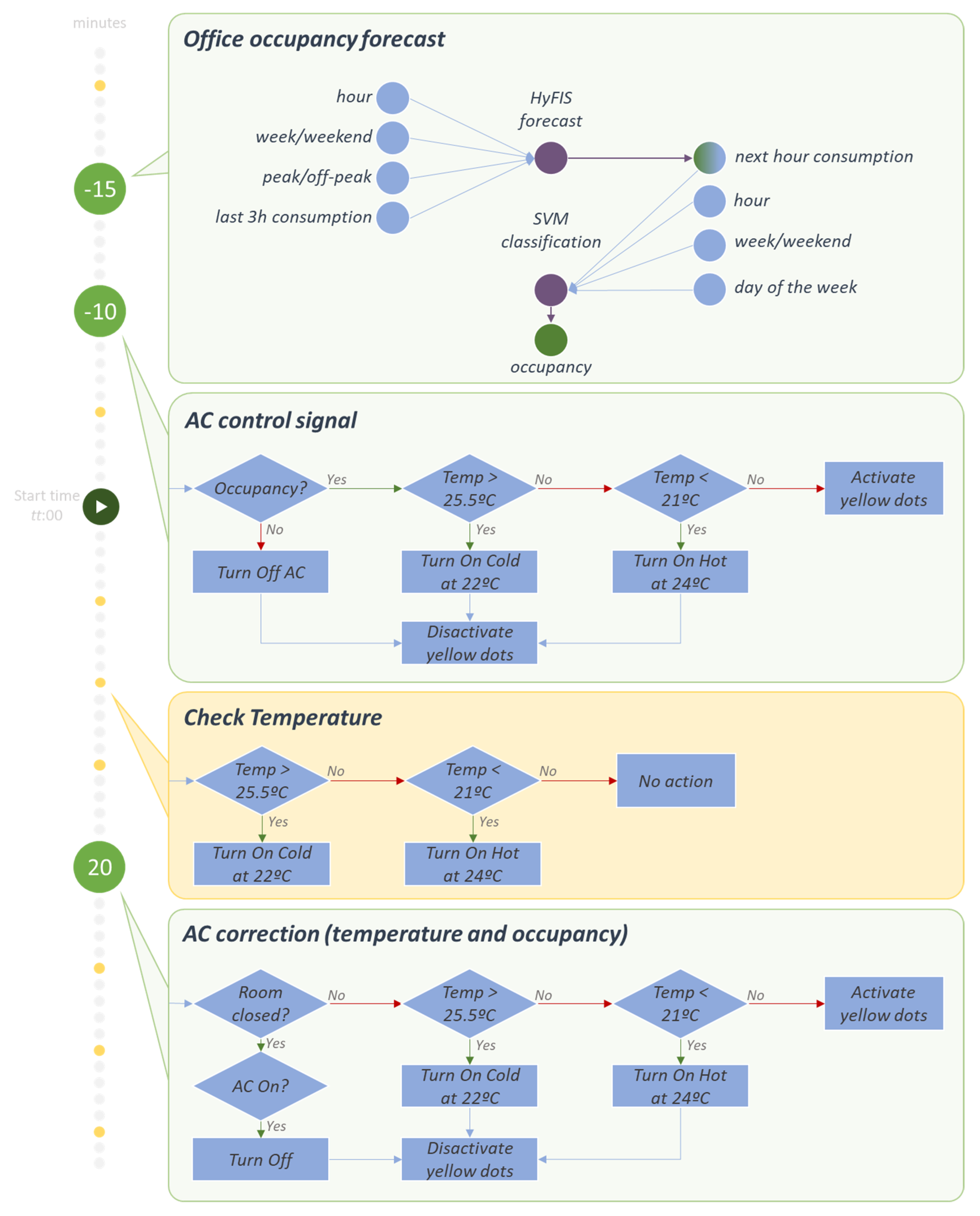
Figure 13 shows the control actions used in the intelligent HVAC control system.
Fifteen minutes before the hour starts, the system estimates the occupancy of the room during the next hour using two processes: forecasting the energy consumption of the room during the target hour, and forecasting the occupancy of the room based on the forecasted energy consumption value. The consumption forecasting starts at fifteen minutes before each hour, using a hybrid neural fuzzy inference system (HyFIS) algorithm. This forecasting method implements a combination of neuronal networks and fuzzy rule-based systems [
34]. The HyFIS, seen in
Figure 13, receives a combination of four effective variables on the energy consumption value from past seven days as train data to create the forecasting model and based on the same variables from the current hour estimates the consumption value for the next hour. In the following of this process, a support vector machine (SVM) [
35] classification algorithm has been used to identify the occupancy of the room. This classification method receives the estimated consumption value from HyFIS. The SVM also receives the same data set from the past six days to create the classification model and finally based on this model and the input data, the method returns a 0 or 1 result. Which in this case, 1 means that during the next hour at least one person will be in the room and 0 mean that the room during the next hour will be empty. At ten minutes before each hour, the system will act according to the SVM classification result and the real-time temperature value. At this moment the system will take one of four actions:
Turn off the air conditioner unit—this action will be taken if there will be no expected occupancy in the next hour period;
Turn on the air conditioner unit at 22 °C in cold mode—this action will be taken if occupancy is expected and the room’s temperature is higher than 25.5 °C;
Turn on the air conditioner unit at 24 °C in heat mode—this action will be taken if occupancy is expected and the room’s temperature is below than 21 °C;
Turn on the 5 min monitoring (the yellow dots of
Figure 13)—this action will be taken if occupancy is expected and the room’s temperature is between 21 °C and 25.5 °C.
After the first control action, the intelligent HVAC control system runs an error check at twenty minutes after the beginning of the hour. The system will use the light intensity sensor inside the room to detect if the room is at use or closed. If the room is closed and the HVAC unit is turned on, then the system will turn off the unit. Otherwise, it will take one of the last three actions presented before: turn on at cold, turn on at heat or turn on the 5 min monitoring.
The five-minute monitoring system is activated every time occupancy is expected or the room is open and when the temperature in between 21 °C and 25.5 °C. In these conditions the HVAC unit will not be turned on. Therefore, a monitoring process is activated and run every 5 min to check the room’s temperature and if the temperature overpasses or underpasses the range between 21 °C and 25.5 °C, then the HVAC unit will be turned on.
4. Proposed Architecture Deployment
In this section will be described the subsystems deployment in our office building, as well as the IoH work regarding metadata and users’ preferences.
4.1. Building’s Description
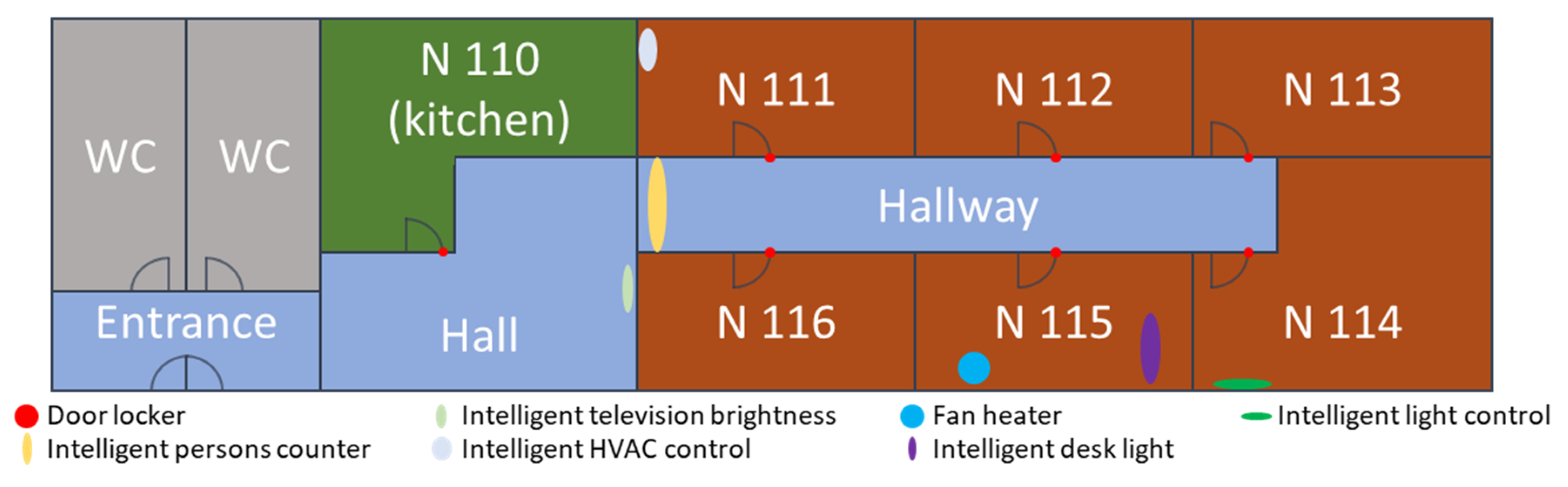
The building’s layout where IoH was deployed is shown in
Figure 14. There are no doors between entrance, hall, and hallway, the drawn walls between these zones only represent a logical separation. The intelligent persons counter system is in the border between the hall and the hallway, meaning that people in entrance, WCs, hall and kitchen are not counted. The location of the integrated IoT devices and other subsystems can be found in
Table 1.
The building is daily used by around 15 persons, between researchers and students. The last two rooms in the building, N 113 and N 114, are two working laboratories, while N 111, N 112, N 115 and N 116 are researchers’ offices.
4.2. Integration Metadata
In this paper, two types of IoT devices are used: door locker and smart plugs. The integration of such devices is done using Home Assistant open source platform that provides several IoT devices compatibilities. The metadata of these devices is shown in
Table 1. The metadata associated with each of the subsystems of
Section 3 is also shown in
Table 1. The
Triggered by column represents the condition needed to start that device/subsystem, the
Impacts column indicates the variables impacted by the use of each device/subsystem, the
Measures column indicates the sensors and the
Indicates column identifies the status that the system can indicate.
The metadata is used in IoH to perform contextual actions, contextual decision support and the fire of warnings and alarms. The right definition of metadata is vital for the good functionality of the IoH platform. Therefore, this configuration should be carefully done.
4.3. Users’ Preferences
Besides the metadata associated with each integrated resource, IoH platform requires the parameterization of users’ preferences for each building’s zone. Each zone is configured so the IoH platform can match the users’ preferences with the building’s automation provided by the integrated devices and systems.
The preferences values are related to the actuation power in each zone. For instance, N 115 and N 111 zones have a 24 °C temperature defined as users’ preference—the temperature is mandatory to define because a fan heater that has an impact in the room’s temperature is placed inside this zone. Moreover, zones N 114 and N 115 also have a lux level that indicates the users’ preferences for these zones, 500 lux, and 1000 lux respectively.
4.4. Metadata and Users’ Preferences Interpretation
The impact column of
Table 1 is defined by positive impacts that a device can cause in the room—in other words, the system only considers impact as an increase reaction in the metadata value. For instance, the Fan Heater device has an increasing impact on the room’s temperature. Currently, the system does not consider negative or decreasing, impacts. The system uses Boolean values to represent the device’s impacts, to enable negative impacts the system should consider another type of values, such as integers or bytes.
The system uses metadata to combine same zone devices according to the measured values and the impacted values. In this case, only two matches are found:
The temperatures value measured by the intelligent desk light are affected by the fan heater;
The shutters status measured by the intelligent light control are affected by the same device; intelligent light control.
The users’ preferences enter the system as triggered values that are able to turn off subsystems. For instance, if the temperature of room N 115 reaches 24 °C, IoH will automatically turn off the heating devices of that room (i.e., Fan heater). Moreover, IoH can manage subsystems according to users’ preferences, as will be seen in
Section 5.3. To enable this control, the same mapping of measured/impact is performed between users’ preferences and the devices’ impact values. The final matches are:
The fan heater device has an impact in the temperature of office N 115, where the users’ preference is established for 24 °C;
Intelligent HVAC control subsystem has an impact in the temperature of office N 111, where the users’ preference is established for 24 °C;
Intelligent light control subsystem has an impact in the light of office N114, that is defined for 500 lux in the users’ preferences;
Intelligent desk light subsystem has an impact in the light of office N115, that is defined for 1000 lux in the users’ preferences.
The mapping between measured values and impact values, and the mapping between measured values and users’ preferences enable the smart control of IoH using third-party devices and subsystems. IoH will actuate on top of these devices and subsystems to provide a top-level control to improve users’ comfort. IoH is also able to produce security warnings and alarms, as will be seen in
Section 5.4 and
Section 5.5.
5. Results
The presented results of this section take into account the deployment of the IoH platform in one of our buildings. The building layout and description are presented in
Section 4.
5.1. Intelligent Persons Counter System Results
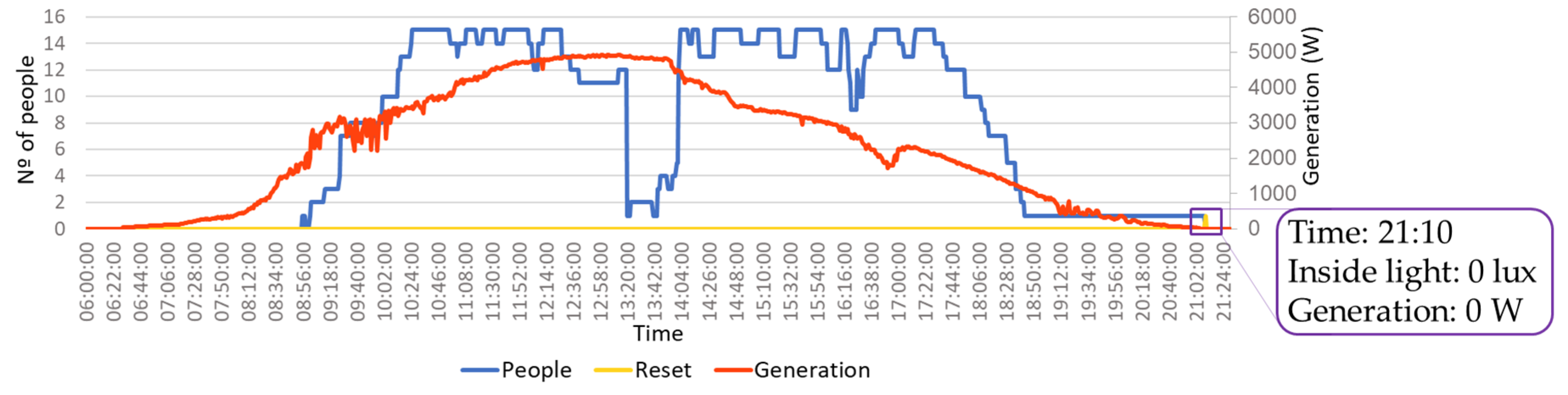
The intelligent persons counter system, as previously explained, uses a webcam feed to detect persons and movements. The system also uses generation and inside light measures to conduct a counting reset. The presented results report a working day with 15 persons at the building. Because there is no official schedule, people usually start their work between 9:00 a.m. and 10:30 a.m. and finish it between 5:30 p.m. and 6:30 p.m.
The presented results, shown in
Figure 15, represents the values read from 6:00 a.m. and 9:30 p.m. The chosen day presents a counting error where the system was not able to rightly count the left of the people, resulting in a counting error after everyone is leaving. This enables us to see the reset working. The reset mechanism is performed every five minutes and it was triggered at 9:10 p.m. when the generation reaches 0 W, inside light was 0 lux and the counter was different than 0.
5.2. Intelligent Television Brightness Control Results
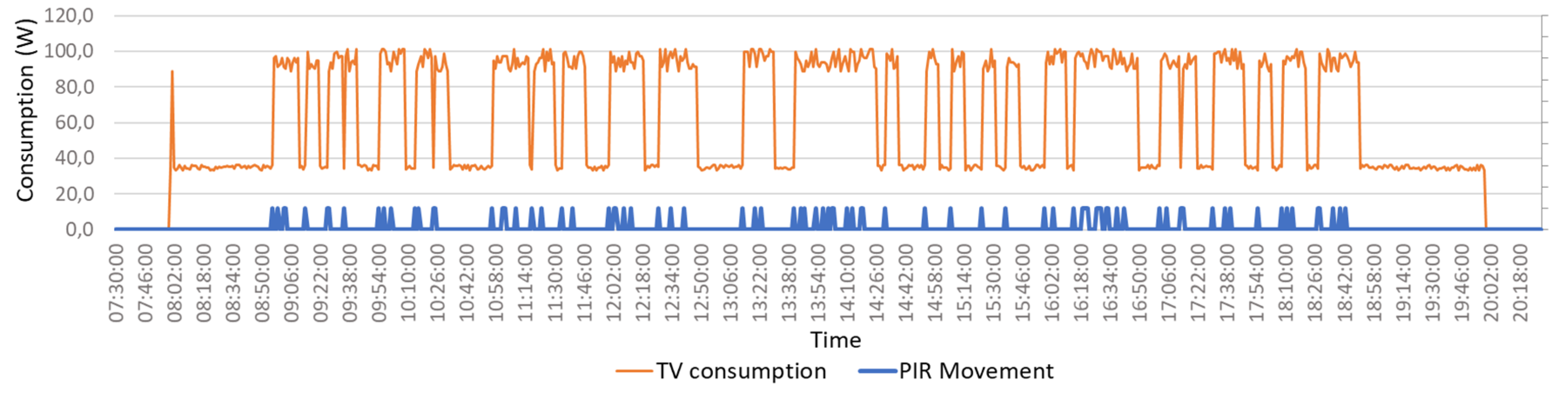
The intelligent television brightness control works 24 h a day. However, the television smart plug has an internal schedule that turns on the television between 8:00 a.m. and 8:00 p.m. The results of
Figure 16 chart disregard the night period—where the television is off—and only considers values from 7:30 a.m. to 8:30 p.m. The television consumption varies from 35 W, in its lowest brightness, and 95 W, in its highest brightness.
At 8:00 a.m., the smart plug turns on the television and by default, the television will use the power mode where the brightness is highest. However, the intelligent television brightness control will read the smart plug’s consumption and detect that the television is in its highest brightness mode even though there was no movement in the last five minutes. As result, the system will change the television power mode to the lowest brightness, resulting in a consumption reduction. The power mode with the highest brightness will be used every time the system detects movement.
As can be seen in
Figure 14, the hall—where the television is placed—is near the persons intelligent counting system. Therefore, the detection of movement near television will almost result in a passage of people in the counter system. And for that reason, the movement shown in
Figure 16 chart can be overlapped in the counter system chart of
Figure 15.
5.3. IoH Zone Heater Control Results
IoH platform enables the combination between the integrated devices and subsystems using their metadata. This section will show how IoH can control an IoT device using the data feeding from a subsystem.
In this case, a smart plug is connected to a fan heater in the same room where the intelligent desk light control system is located. The metadata of the fan heater smart plug indicates an impact in the temperature while the intelligent desk light control system is defined in its metadata as having a temperature sensor. Metadata of both also defined the same room as their building’s position. Moreover, the metadata of the fan heater indicates movement as the actuator signal. By combining their metadata with the users’ preferences set in IoH platform, it is possible to automatically control the fan heater to provide the user’s desired room’s temperature in an autonomous and contextual way.
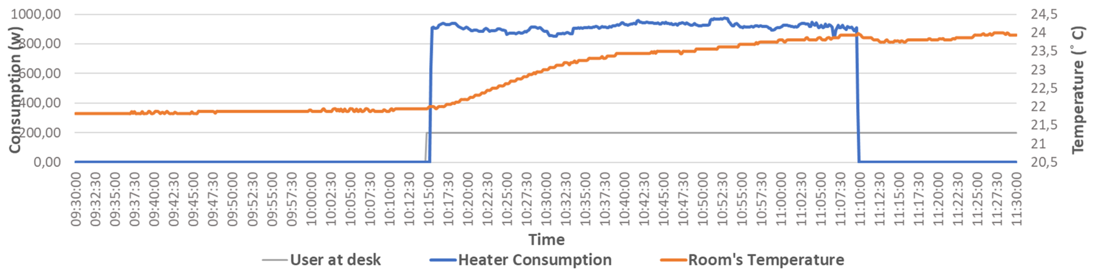
Figure 17 shows the IoH control over the fan heater. The user of this room passes in the counter system at 10:14 a.m., as can be seen in
Figure 15, and is detected close to the television system at the same time, as can be seen in
Figure 16. When the user is detected in the desk light control system, the IoH checks the room’s temperature and matches the real-time value with the user’s preference of 24 °C. If the real-time temperate falls under the desired temperature, then the fan heater’s smart plug is turned on. The heater consumption, after it is turned on, is shown in the
Figure 17 chart at 10:15 a.m. When the temperature reaches the user’s preference temperature, the fan heater is turned off. After the fan heater is turned off the room’s temperature slightly decreases because the air flow was stopped.
The zone heater control was performed entirely by the IoH platform using the metadata of the integrated IoT device—smart plug—and the intelligent desk light control subsystem. The user only needed to set the room’s temperature preference and the system was able to automatically control the heater according to the room’s context.
5.4. IoH Building’s “Not Secure” Warning System
IoH platform is also able to fire warnings and alarms using the metadata of the integrated devices and subsystems. In this section, the IoH capability of firing warnings regarding dangerous situations is described. By default, IoH checks if the building is closed when there is no person inside and fires a warning if the security check did get some unclosed zone/room.
The building’s not secure warning system monitors the number of persons inside the building. The warning is fired locally in the IoH graphical interfaces and if the user does not overwrite or solve the problem, then IoH will send an email warning all IoH building’s administrators.
The warning uses the metadata from the intelligent persons counter system to read the number of persons inside the building and then will check the building’s status using the “room closed” indication in metadata from:
Doors’ lockers—this IoT resource provides information regarding the doors’ status (i.e., if open or closed);
Intelligent light control—this subsystem provides the current status of the windows;
Intelligent HVAC control—this subsystem provides information regarding the current status of the air conditioner.
Using the chart of
Figure 15, IoH will check if the building is closed at 9:10 p.m., when the people counter goes to zero. At this time, the IoH platform will check the defined “room closed” indication metadata to see if there is something open, and if so, it will show a warning in the graphical interfaces.
5.5. IoH Building’s Intrusion Alarm System
The building’s intrusion alarm system detects unexpected intrusions in the building when it should be closed. The IoH building’s intrusion alarm system is an event-driven monitoring process that is running when the persons counter is equal to zero. Unlike the previous warning system, the alarm system listens to the building’s status changes that represent human activity. The alarm system uses email to communicate with the IoH administrator users.
When the person counter is zero, the IoH platform will monitor changes in the “human presence” indication metadata and the alarm will be the trigger if some change is detected. The integrated devices and subsystems that will be monitor are:
Doors’ lockers—these devices are able to detect the opening of the door when no one was supposed to be inside the building;
Intelligent light control—the PIR sensors provide the movement detection inside the room;
Intelligent desk light control—this subsystem can detect a person in the desk.
The PIR sensor of the intelligent television brightness control subsystem is not used because it is placed before the intelligent persons counter system. Therefore, this PIR is always triggered before the first person enters the building, and because of that, the PIR is not monitored in the building’s intrusion alarm system.
6. Conclusions
This paper proposes a new Intelligent of Home (IoH) platform architecture. The IoH platform does not provide the development and specification of hardware, enabling the exclusive use of third-party hardware. The platform enables the integration of third-party devices—sensors and/or actuators—and systems. The use of integrated devices and systems is done by describing each integration with metadata that will be matched and used in IoH platform.
The main goal of this paper is the proof of concept of IoH platform regarding the context awareness capabilities. The results of the IoH zone heater control, the IoH building’s warning system, and the IoH building’s intrusion alarm system proves the ability of IoH to combine multiple third-party devices and systems to achieve a contextual awareness solution. The combination of such systems enables the interoperability and scalability of the system.
IoH is also oriented for considering ambient intelligence. Considering the seven different phases of the intelligent behavior in AmI Scenarios proposed in [
24], we observe that they are all considered in IoH, namely:
Interpreting the environment’s state (by using different types of raw sensors to detect temperature, luminosity, and movement; or cameras);
Representing the information and knowledge associated with the environment (namely the knowledge related with each subsystem presented in
Section 3);
Modeling, simulating and representing entities in the environment (representation of all systems in the home);
Planning decisions or actions (planning the changes in different devices in a coordinated mode);
Learning about the environment and associated aspects (the forecast of the room’s usage for the HVAC system is a good example);
Interacting with humans (in the user interface layer available in the IoH subsystems);
Acting on the environment (by actuation in different systems like the lights, air conditioning, windows shutters, and television brightness control).
The IoH platform will not replace hardware or software. IoH platform is a new layer for smart homes that goes on top of the existing systems to provide contextual awareness am ambient intelligence management.


